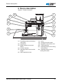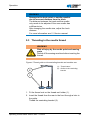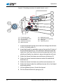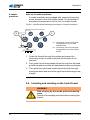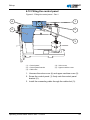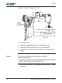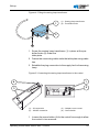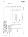
1
H868 Operating Manual All rights reserved. Property of Dürkopp Adler AG and protected by copyright. Any reuse of these contents, including extracts, is prohibited without the prior written approval of Dürkopp Adler AG. Copyright © Dürkopp Adler AG - 2013 Table of contents 1 About this manual ...............................................................................3 1.1 1.2 1.3 1.4 1.5 1.6 1.7 Area of applicability ...............................................................................3 Target group ..........................................................................................3 Symbols and characters used ...............................................................4 Other documents ...................................................................................4 Liability...................................................................................................5 Transportation .......................................................................................5 Intended use..........................................................................................5 2 Performance description ....................................................................7 2.1 2.2 2.3 2.4 Features ................................................................................................7 Declaration of conformity (CE) ..............................................................8 Additional equipment .............................................................................8 Technical data .......................................................................................9 3 Safety instructions ............................................................................11 3.1 3.2 Basic safety instructions ......................................................................11 Signal words and symbols used in warnings.......................................12 4 Device description.............................................................................15 5 Operation............................................................................................17 5.1 5.2 5.3 5.4 5.5 5.6 5.6.1 5.6.2 5.7 5.8 5.9 5.10 5.11 5.12 5.13 5.14 5.15 5.15.1 5.15.2 5.15.3 5.16 Switching the power supply on and off ................................................17 Inserting and replacing the needle ......................................................18 Threading in the needle thread............................................................19 Inserting and winding on the hook thread............................................22 Replacing the hook thread bobbin.......................................................25 Adjusting the thread tension ................................................................26 Adjusting the needle thread tension ....................................................27 Adjusting the hook thread tension .......................................................28 Setting the thread regulator .................................................................29 Lifting the sewing feet..........................................................................30 Locking the sewing feet in the upper position......................................30 Sewing foot pressure...........................................................................31 Sewing foot stroke ...............................................................................32 Stitch length.........................................................................................34 Setting quick functions at the keypad ..................................................36 Sewing.................................................................................................39 Maintenance ........................................................................................40 Cleaning the machine..........................................................................41 Checking the oil level...........................................................................42 Checking the pneumatic system..........................................................44 Customer service.................................................................................46 6 Set-up .................................................................................................47 Operating manual H868 Version 00.0 - 07/2013 1 Table of contents 6.1 6.2 6.3 6.4 6.5 6.6 6.7 6.8 6.9 6.10 6.11 6.11.1 6.11.2 6.12 6.13 6.13.1 6.13.2 6.13.3 6.14 6.14.1 6.14.2 6.15 6.16 Checking the scope of delivery............................................................47 Removing the transport securing devices ...........................................49 Fitting the frame components ..............................................................49 Fitting the pedal ...................................................................................50 Completing the table plate...................................................................50 Fastening the table plate to the frame .................................................52 Fitting the controller .............................................................................53 Fitting the setpoint device....................................................................54 Inserting the machine upper section....................................................55 Fitting the oil extraction line .................................................................56 Fitting the knee lever ...........................................................................57 Fitting the electric knee lever...............................................................57 Fitting the mechanical knee lever ........................................................58 Fitting the control panel .......................................................................59 Electrical connection............................................................................61 Fitting the sewing lamp........................................................................61 Fitting and connecting the sewing lamp transformer ...........................62 Connecting the direct drive..................................................................64 Pneumatic connection .........................................................................64 Fitting the maintenance unit ................................................................64 Setting the operating pressure ............................................................66 Lubrication ...........................................................................................67 Sewing test ..........................................................................................69 7 Decommissioning..............................................................................71 8 Disposal..............................................................................................73 9 Appendix ............................................................................................75 2 Operating manual H868 Version 00.0 - 07/2013 About this manual 1 About this manual This operating manual for the special sewing machine H868 was compiled with the utmost care. It contains information and notes in order to make long-term and reliable operation possible. Should you notice any discrepancies or if you have improvement requests, then we would be glad to receive your feedback, Section 5.16 Customer service. Please regard the operating manual as part of the product and keep it in a safe place where it can be easily accessed. Read the operating manual completely prior to using the unit for the first time. Only pass the product on to third parties together with the operating manual. 1.1 Area of applicability This manual describes the intended use and the set-up of the special sewing machine H868. 1.2 Target group The operating manual is intended for: • Operating personnel: This group of employees has been trained in operating the machine and can access the operating manual. Specifically Section 5 Operation is important for this group of employees. • Specialized staff: This group of employees has the appropriate technical training allowing them to perform maintenance on the sewing unit or to repair faults. Specifically Section 6 Set-up is important for this specialized staff. Service instructions are supplied separately. With regard to minimum qualification and other requirements to be met by the personnel, please also observe Section 3 Safety instructions. Operating manual H868 Version 00.0 - 07/2013 3 About this manual 1.3 Symbols and characters used Different information is depicted or highlighted in this operating manual by the following characters for easier and quicker understanding: Symbol/character Meaning • Lists are identified by bullet points. 1. Instructions are numbered and have to be performed in the specified order. 2. References to further information in this operating manual or other documents are identified by this symbol. Safety Important warnings for the user of the sewing machine are specifically marked. Because safety constitutes an area of major importance, hazard symbols, levels of risk, and their signal words are described separately in Section 3 Safety instructions. Location information Information on where something is positioned using the terms "right" or "left" must always be regarded from the operator's point of view if the figure gives no other obvious indication for determining the location. 1.4 Other documents The device contains built-in components from other manufacturers. The respective manufacturers have carried out hazard assessments for these purchased parts and confirmed compliance of the design with the applicable European and national regulations. The intended use of the built-in components is described in the corresponding manuals of the manufacturers. 4 Operating manual H868 Version 00.0 - 07/2013 About this manual 1.5 Liability All information and notes in this operating manual have been compiled in accordance with the latest technology and the applicable standards and regulations. The manufacturer accepts no liability for any damage due to: • • • • • • Breakage and transport Failure to observe the operating manual Improper use Unauthorized modifications to the machine The deployment of untrained personnel Using spare parts not approved 1.6 Transportation Dürkopp Adler cannot be held liable for any damage during transport. Check the delivered product immediately after receiving it. Report any damage to the last transport manager. This also applies if the packaging is not damaged. Keep the machines, devices, and packaging material in the condition they were at the time the damage was identified. That secures any claims towards the transport company. Report all other complaints to Dürkopp Adler immediately after receiving the product. 1.7 Intended use The Dürkopp Adler H868 is for intended for sewing moderately heavy to heavy material. Moderately heavy material requires needles strengths of 140 – 180 Nm, heavy material requires needles strengths of 180 - 250 Nm. The machine is only intended for processing dry material. The material must contain no hard objects. The sewing machine is intended for industrial use. The machine may only be set up and operated in dry conditions on well-maintained premises. If the machine is operated on premises that are not dry and well-maintained, then further measures may be required which must be compatible with EN 60204-31:1999. Only authorized/trained persons may work on the machine. Operating manual H868 Version 00.0 - 07/2013 5 About this manual The manufacturer will not be held liable for damage resulting from improper use. WARNING Danger due to high voltage, crushing and sharp objects. Improper use can result in injuries. Please follow all instructions in the manual. ATTENTION Improper use could result in material damage. Please follow all instructions in the manual. 6 Operating manual H868 Version 00.0 - 07/2013 Performance description 2 Performance description The Dürkopp Adler special sewing machine H868 is equipped with an extra-large 3XL hook with a 40 mm bobbin diameter. The clearance under the sewing feet when lifted is max. 25 mm. The subclasses have a DC drive with a reversing mechanism, required in order to position the needle above the feet. The special sewing machine positions the needle at the end of the seam and has an electropneumatic foot lifter above the sewing pedal. A safety snap-on coupling prevents any misadjustment or damage to the hook in the event of a thread jamming. Automatic wick lubrication with an oil level indicator at the column eases lubrication of the machine and hook. The special sewing machine is equipped with a 6-key keypad. An additional switch is located in easy reach of the sewer and can be assigned 6 functions. Possible operating functions: • • • • • • Manual sewing in reverse Needle up / down Call up the start or end strip or bartack suppression Second stitch length Switchable thread tension Lower the middle stop 2.1 Features Upper part of the machine • Single-needle column double lockstitch version • Double-needle column double lockstitch version Operating manual H868 Version 00.0 - 07/2013 7 Performance description 2.2 Declaration of conformity (CE) The machine complies with the European regulations specified in the declaration of conformity or in the installation declaration. 2.3 Additional equipment A flexible system of additional equipment allows optimal, low-cost equipping of the special sewing machine to suit the respective application. Order number = Standard equipment = Optional expansion Additional equipment H868190361 H868290361 0868 590014 Residual-thread monitor for the hook thread, 3XL hook, 1-needle machines 0868 590024 Residual-thread monitor for the hook thread, 3XL hook, 2-needle machines 0867 490010 Operating panel bracket 9822 510003 Halogen sewing lamp for upper sewing machine section 9880 867100 Sewing lamp attachment set 0798 500088 Sewing lamp transformer for halogen sewing lamp 9880 867103 1-diode sewing lamp with attachments 9880 867118 Integrated diode sewing lamp 9850 001089 Power supply unit for integrated sewing lamp and 1-diode sewing lamp 0797 003031 Pneumatic connection package for connecting frames with maintenance unit N800 080007 Rollers and straight stop 8 Operating manual H868 Version 00.0 - 07/2013 Performance description Order number Additional equipment H868190361 H868290361 N800 080033 Swiveling end stop, with stop, roller and seam middle guide N800 005650 Seam center guide from front, pneumatically switched 9835 901005 Memo dongle, external memory, for data transmission with DA Classic control 0867 590984 Thread clamp with thread wiper function (FK kit) 9081 300001 Tool set for M-type 0867 590684 Electronic handwheel MG55 400364 Frame set for motor, attached to the upper section, table plate 1060 x 600 mm with pedal (MG 55-3) 2.4 Technical data Technical data H868190361 Length/width/height [mm] Weight without/with direct drive [kg] H868290361 650/280/690 72 74 stitch type Lockstitch 301 Hook type Vertical, oversize (3XL) Number of needles Needle system Maximum needle strength [Nm] Sewing thread thickness Stitch length, forwards / backwards [mm] Number of adjustable stitch lengths Maximum number of stitches Operating manual H868 Version 00.0 - 07/2013 1 2 328 (794 and 7x23 are possible after conversion) 250 8/3, braided thread 1.2 mm 12 / 12 2 1800 9 Performance description H868190361 Technical data H868290361 Number of stitches on delivery 1600 Stitch quantity reduction for stitch lengths of 6 – 12 mm 1200 Stitch quantity reduction for strokes of 1 – 3 mm 1800 Reduction of the number of stitches with stroke exceeding 4 mm 1500 Reduction of the number of stitches with stroke exceeding 6 mm 1200 Reduction of the number of stitches with stroke exceeding 9 mm 1000 Maximum stroke height (only with reversing mechanism) 25 Maximum sewing foot stroke 9 Positive operating pressure [bar] 6 Air consumption [NL] 0.7 Rated voltage [V/Hz] 1x230 V - 50/60 Hz Rated power [kVA] 10 375 W Operating manual H868 Version 00.0 - 07/2013 Safety instructions 3 Safety instructions This section contains basic instructions for your safety. Read the instructions carefully before setting up, programming, maintaining, or operating the machine. Make sure to follow the information included in the safety instructions. Failure to do this can result in serious injury and damage to the machine. 3.1 Basic safety instructions The machine may only be used as described in this manual. The operating manual must be available at the machine's location at all times. Work on live components and equipment is prohibited. Exceptions are defined in the specifications in DIN VDE 0105. For the following work, the machine must be disconnected from the power supply using the main switch or by disconnecting the power plug: Replacing the needle or other sewing tools Leaving the workplace Performing maintenance work and repairs Incorrect or faulty spare parts can impair safety and damage the machine. Therefore only use original spare parts from the manufacturer. Feed Use a sturdy lifting carriage or forklift for transporting the machine. Raise the machine max. 20 mm and secure it against slipping off. Set-up The connecting cable must have a power plug approved in the specific country. The power plug may only be connected to the power cable by a qualified specialist. Operator's obligations Observe the country specific safety and accident prevention regulations and the legal regulations concerning industrial safety and the protection of the environment. All warnings and safety signs on the machine must always be in legible condition and may not be removed. Missing or damaged labels must be replaced immediately. Operating manual H868 Version 00.0 - 07/2013 11 Safety instructions Requirements to be met by the personnel The machine may only be set up by qualified specialists. Maintenance work and repairs may only be carried out by qualified specialists. Work on electrical equipment may only be carried out by qualified specialists. Only authorized persons may work on the machine. Every person who works on the machine must have read the operating manual first. Operation Inspect the machine while in use for any externally visible damage. Interrupt your work if you notice any changes to the machine. Report any changes to your supervisor. A damaged machine may not be used any more. Safety equipment Safety equipment may not be removed or put out of service. If this cannot be avoided for a repair operation, the safety equipment must be refitted and put back into service immediately afterwards. 3.2 Signal words and symbols used in warnings Warnings in the text are distinguished by color bars. The color scheme is oriented towards the severity of the danger. Signal words specify the severity of a danger: Signal words Signal words and the endangerment that they describe: Signal word Symbols Endangerment DANGER Resulting in death or serious injury. WARNING Death or serious injury possible. CAUTION Moderate to minor injuries possible. ATTENTION Damage possible. In the case of dangers to personnel, the following symbols indicate the type of hazard: Symbol Type of danger General danger 12 Operating manual H868 Version 00.0 - 07/2013 Safety instructions Symbol Type of danger Danger due to electric shock Danger due to sharp objects Danger due to crushing Examples Examples of the layout of the safety instructions in the text: DANGER Type and source of the danger Consequences in the event of noncompliance Measures for avoiding the danger This is what a hazard note looks like for a hazard that will result in serious injury or even death if not complied with. WARNING Type and source of the danger Consequences in the event of noncompliance Measures for avoiding the danger This is what a hazard note looks like for a hazard that could result in serious injury or even death if not complied with. CAUTION Type and source of the danger Consequences in the event of noncompliance Measures for avoiding the danger This is what a hazard note looks like for a hazard that could result in moderate or minor injury if not complied with. Operating manual H868 Version 00.0 - 07/2013 13 Safety instructions ATTENTION Type and source of the danger Consequences in the event of noncompliance Measures for avoiding the danger This is what a hazard note looks like for a hazard that could result in material damage if not complied with. ATTENTION Type and source of the danger Consequences in the event of noncompliance Measures for avoiding the danger This is what an hazard note looks like for a hazard that could result in environmental damage if not complied with. 14 Operating manual H868 Version 00.0 - 07/2013 Device description 4 Device description Figure 1: Product overview 12 1 11 2 10 3 9 4 8 5 7 6 (1) - Unwinding bracket with thread reel holder (2) - Handwheel (3) - Bobbin winder for the hook thread (4) - Oil level indicator (5) - Adjusting wheels for the stitch length (6) - Stitch adjustment lever Operating manual H868 Version 00.0 - 07/2013 (7) (8) (9) (10) (11) - Hook Sewing foot with needle Keypad on the machine arm Thread tensions Adjusting wheel for the sewing foot pressure (12) - Adjusting wheels for the sewing foot stroke 15 Device description 16 Operating manual H868 Version 00.0 - 07/2013 Operation 5 Operation 5.1 Switching the power supply on and off The lower main switch (2) on the control regulates the power supply. Figure 2: Switching the power supply on and off 1 2 3 4 (1) (2) (3) (4) - Switch for the sewing lamp Main power supply switch Indicator lamp on the controller Indicator lamp on the keypad for quick functions To switch on the power: • Press the main switch (2) down to position I. The indicator lamps (3) and (4) light up. To switch off the power: • Press the main switch (2) up to position 0. The indicator lamps (3) and (4) go out. Operating manual H868 Version 00.0 - 07/2013 17 Operation 5.2 Inserting and replacing the needle WARNING Risk of injury by the needle point and moving parts Switch off the sewing machine before replacing the needle. Do not touch the needle point. Figure 3: Inserting and replacing the needle 1 4 2 (1) (2) (3) (4) - Needle bar Needle screw Hook Groove 3 1. Turn the handwheel back until the needle bar (1) reaches the upper end position. 2. Loosen the needle screw (2). 3. Pull the needle out towards the bottom. 4. Insert the new needle. 5. Align the needle in such a way that the groove (4) faces the hook (3). 6. Tighten the needle screw (2). 2-needle machines Note on 2-needle machines: The procedure for the second needle of 2-needle machines is identical. • Align the needles in such a way that the grooves face away from each other. Each groove then faces the hook that belongs to this needle. 18 Operating manual H868 Version 00.0 - 07/2013 Operation WARNING Damage to the hook point or needle possible due to incorrect distance from the hook. The distance between the hook and the needle only needs to be adjusted if the new needle has a different size. After changing the needle size, adjust the hook distance. For more information see Service manual. 5.3 Threading in the needle thread WARNING Risk of injury by the needle point and moving parts Switch off the sewing machine before inserting the thread. Figure 4: Thread guide on the unwinding bracket and machine arm 2 (1) - Thread stand (2) - Guide on the unwinding bracket 1 1. Fit the thread reel on the thread reel holder (1). 2. Insert the thread from the rear to the front through a hole in the guide. Thread the unwinding bracket (2). Operating manual H868 Version 00.0 - 07/2013 19 Operation Figure 5: Threading procedure for needle thread – part 1 1 2 4 5 6 9 3 4 5 6 8 7 (1) (2) (3) (4) (5) - First thread guide Second thread guide Pre-tensioner Additional tensioner Main tensioner (6) (7) (8) (9) - Additional screw Thread tensioning spring Spring tip Tightening lever 1. Insert the thread from the rear to the front through the left hole in the 1st thread guide (1). 2. Insert the thread in a wavelike manner through the 3 holes of the 2nd thread guide (2): From above to below through the right hole, then from below to above through the hole in the middle and finally from below to above through the left hole. 3. Guide the thread clockwise around the pre-tensioner (3). 4. Guide the thread counterclockwise around the additional tensioner (4). 5. Guide the thread clockwise around the main tensioner (5). 6. Guide the thread under the additional screw (6) to the thread tensioning spring. 7. Lift the tightening lever (9) with the thread. 8. Pull the thread under the spring tip (8). 20 Operating manual H868 Version 00.0 - 07/2013 Operation Figure 6: Threading procedure for needle thread – part 2 10 16 15 11 (10) (11) (12) (13) (14) (15) (16) - Thread lever Thread regulator Needle eye Thread guide on the needle bar Lower thread guide Upper thread guide Hook 14 13 12 9. Guide the thread under the hook (16). 10. Insert the thread from bottom to top through the hole on the thread regulator (11). 11. Insert the thread from the right to the left through the thread lever (10). 12. Insert the thread through the upper thread guide (15). 13. Insert the thread through a hole in the lower thread guide (14). 14. Insert the thread through the thread guide on the needle bar (13). 15. Insert the thread through the needle eye (12) in such a way that the loose thread end faces the hook. 16. Pull the thread through the needle eye (12) until the loose thread end has a length of 4 cm in the highest position at the thread lever (10). Operating manual H868 Version 00.0 - 07/2013 21 Operation 2-needle machines Note on 2-needle machines: 2-needle machines are equipped with a second tensioning screw triangle for the 2nd needle thread. The threading-in procedure corresponds to that for the 1st needle thread. 1 – – 2 + + Figure 7: Needle thread threading procedure for 2-needle machines – + (1) - Tensioning screws in triangular arrangement for the second needle thread (2) - Tensioning screws in triangular arrangement for the first needle thread – + + – + 1234 + – – 1. Guide the threads through the guides and around the tensioning screws in such a way that the threads do not intersect. 2. First guide the left-hand needle thread through the left-hand guide holes and around the left-hand tensioning screw triangle. 3. Then guide the right-hand needle thread through the righthand guide holes and around the right-hand tensioning screw triangle . 5.4 Inserting and winding on the hook thread WARNING Risk of injury by the needle point and moving parts Switch off the sewing machine before inserting the thread. 22 Operating manual H868 Version 00.0 - 07/2013 Operation Figure 8: Thread guide on the unwinding bracket and machine arm (1) - Thread stand (2) - Guide on the unwinding bracket 2 1 1. Fit the thread reel on the thread reel holder (1). 2. Insert the thread from the rear to the front through a hole in the guide on the unwinding bracket (2). Figure 9: Winding on the hook thread - part 1 1 5 2 4 5 6 4 4 5 6 3 (1) - 1st thread guide (2) - Hook thread guide (3) - Winder (4) - Hook thread winding tension (5) - 2nd thread guide 1. Insert the thread from the rear to the front through the right hole in the 1st thread guide (1). 2. Insert the thread in a wavelike manner through the 3 holes of the 2nd thread guide (5): from top to bottom through the left hole, from bottom to top through the hole in the middle and finally from top to bottom through the right hole. Operating manual H868 Version 00.0 - 07/2013 23 Operation 3. Guide the thread clockwise around the hook thread winding tensioner (4). 4. Insert the thread in a wavelike manner through the 2 holes of the hook thread guide (2): from bottom to top through the left hole and from top to bottom through the right hole. 5. Guide the thread to the winding bobbin (3). Figure 10: Winding on the hook thread - part 2 1 (1) - Cutter (2) - Winder (3) - Winding lever 2 3 1. Clamp the thread behind the cutter (1) and tear off the loose end behind it. 2. Fit the bobbin on the winder (2). 3. Turn the bobbin clockwise until it clicks. 4. Pull the bobbin lever (3) up. The hook thread is normally wound on when sewing is in progress. However, you can also wind on the hook thread without sewing material, e.g. if you require a full bobbin in order to start sewing. ATTENTION Damage to the sewing feet or needle plate possible if the thread is wound on without material. Lock the sewing feet in place in the highest position and adjust the sewing foot stroke to the smallest value if you wind on hook thread without sewing material. 1. Switch on the sewing machine. 2. Press the foot pedal forwards. The machine sews and winds the hook thread from the thread 24 Operating manual H868 Version 00.0 - 07/2013 Operation reel onto the bobbin. When the bobbin is full, the machine automatically stops winding. The bobbin lever moves down. The cutter is automatically moved into its basic vertical position. 3. Pull off the full bobbin. 4. Tear off the thread behind the cutter. 5. Insert a full bobbin in the hook (see Section 5.5 Replacing the hook thread bobbin). 6. Repeat the winding-on procedure with an empty bobbin, as described above. 5.5 Replacing the hook thread bobbin WARNING Risk of injury by the needle point and moving parts Switch off the sewing machine before replacing the hook thread bobbin. Figure 11: Replacing the hook thread bobbin 1 5 2 4 (1) - Hook flap (2) - 1st hook slot (3) - Hook spring 3 (4) - Hook flap guide (5) - 2nd hook slot 1. Lift the hook flap (1). 2. Remove the empty bobbin. 3. Insert the full bobbin so that it moves in the opposite direction of the hook when the thread is pulled out. Operating manual H868 Version 00.0 - 07/2013 25 Operation 4. Guide the hook thread through the 1st hook slot (2). 5. Pull the hook thread under the hook spring (3). 6. Guide the hook thread through the 2nd hook slot (5). 7. Press the hook flap (1) down. 8. Insert the hook thread through the hook flap guide (4). 9. Turn the handwheel until the hook thread comes up. 10. Pull the hook thread and needle thread back together and hold them tight when sewing starts, to avoid jamming the threads. 5.6 Adjusting the thread tension The tension of needle thread and hook thread determines the position of the thread interlacing. If the tension of needle thread and hook thread is identical, the thread interlacing lies in the middle of the material to be sewn. Figure 12: interlacing q w (1) - Identical needle thread and hook thread tension (2) - Hook thread tension higher than needle thread tension (3) - Needle thread tension higher than hook thread tension e 26 Operating manual H868 Version 00.0 - 07/2013 Operation 5.6.1 Adjusting the needle thread tension The 3 tension-adjusting wheels on the tensioning screw triangle determine the needle thread tension. Figure 13: Adjusting the needle thread tension 1 2 (1) - Pre-tensioner (2) - Additional tensioner (3) - Main tensioner 3 The main tensioner (3) determines the normal tension during sewing. The additional tensioner (2) increases the tension during sewing, e.g. for thickened seams. The additional tension (2) is switched on and off using the keypad. The additional tension (2) must always be selected lower than the main tension (3). In the basic position, the top of the adjusting wheel is flush with the screw in the center. To increase the tension: • Turn the adjusting wheel clockwise. To reduce the tension: • Turn the adjusting wheel counterclockwise. The pre-tensioner (1) holds the thread in position if main tensioner (3) and additional tensioner (2) are open completely. Operating manual H868 Version 00.0 - 07/2013 27 Operation 5.6.2 Adjusting the hook thread tension WARNING Risk of injury by the needle point and moving parts Switch off the sewing machine before adjusting the hook thread tension. Figure 14: Adjusting the hook thread tension 1 (1) - Adjusting screw The hook thread tension is adjusted using the adjusting screw (1). To increase the tension: • Turn the adjusting screw (1) clockwise. To reduce the tension: • Turn the adjustment screw (1) counterclockwise. 28 Operating manual H868 Version 00.0 - 07/2013 Operation 5.7 Setting the thread regulator WARNING Risk of injury by the needle point and moving parts Switch off the sewing machine before setting the thread regulator. The thread regulator determines the tension applied to guide the needle thread around the hook. Correct setting: The loop of the needle thread slides at low tension over the thickest point of the hook. Figure 15: Setting the thread regulator 1 (1) - Thread regulator (2) - Regulator screw 2 1. Loosen the regulator screw (2). 2. To increase the tension: Slide the thread regulator (1) to the right. To reduce the tension: Slide the thread regulator (1) to the left. 3. Tighten the regulator screw (2). Operating manual H868 Version 00.0 - 07/2013 29 Operation 5.8 Lifting the sewing feet You use the foot pedal to raise the sewing feet while sewing, e. g. to move the sewn material. Figure 16: Foot pedal 1 (1) - Foot pedal • Press the foot pedal (1) half the way back. The machine stops and raises the sewing feet. The sewing feet remain up as long as the foot pedal is pressed back half the way. If the foot pedal is pressed back completely, the machine sews an end strip and stops sewing. Machines with automatic thread cutter cut the thread off. 5.9 Locking the sewing feet in the upper position There is a lever at the back of the machine for holding the sewing feet in the upper position. Figure 17: Holding the sewing feet in the upper position with the lever 1 (1) - Sewing feet in raised position (2) - Raised position removed 2 30 Operating manual H868 Version 00.0 - 07/2013 Operation To hold the sewing feet in the upper position: • Push the lever down. To cancel the lock: • Push the lever up. You can also use the foot pedal to cancel the upper position: • Press the foot pedal halfway back as when lifting the sewing feet. The lever swivels back up and the lock is removed. CAUTION Risk of crushing when lowering the sewing foot. Do not hold your hands under the sewing foot when the upper position is released via the pedal or lever. 5.10 Sewing foot pressure The adjusting wheel at the top left determines the contact pressure of the sewing foot on the material to be sewn. The pressure can be adjusted continuously by turning the wheel. Figure 18: Adjusting wheel for the sewing foot pressure 1 (1) - Adjusting wheel for the sewing foot pressure To increase the sewing foot pressure: • Turn the adjusting wheel (1) clockwise. Operating manual H868 Version 00.0 - 07/2013 31 Operation To reduce the sewing foot pressure: • Turn the adjusting wheel (1) counterclockwise. ATTENTION Damage to the material possible if the sewing foot pressure setting is incorrect. If the sewing foot pressure is too high, the material could tear. If the sewing foot pressure is too weak, the material could slip. Adjust the sewing foot pressure in such a way that the material to be sewn slides smoothly over the base without slipping. 5.11 Sewing foot stroke The two adjusting wheels in the middle of the machine arm determine how high the sewing feet are raised during sewing. The height can be adjusted continuously on a scale from 1 to 9 by turning the wheels. With 1 the sewing foot is raised the least and with 9 it is raised the highest. Figure 19: Adjusting wheels for the sewing foot stroke 1 2 4 5 6 4 (1) - Adjusting wheel for the normal sewing foot stroke 5 6 (2) - Adjusting wheel for the elevated sewing foot stroke To increase the sewing foot stroke: • Turn the adjusting wheel clockwise. To reduce the sewing foot stroke: • Turn the adjusting wheel counterclockwise. The left adjusting wheel (1) determines the normal sewing foot stroke. 32 Operating manual H868 Version 00.0 - 07/2013 Operation The right adjusting wheel (2) determines the elevated sewing foot stroke. It is used for example when sewing thicker parts of the material. Figure 20: Knee lever 1 (1) - Knee lever (2) - Switch 2 The elevated sewing foot stroke is activated using the knee lever (1). There is a switch (2) at the back of the knee lever (1), which determines whether the sewing foot stroke is applied continuously or only as long as the knee lever is pressed. For permanent conversion: 1. Turn the switch (2) up. 2. Press the knee lever (1) to the right to switch on the elevated sewing foot stroke. 3. Press the knee lever (1) to the right again to switch off the elevated sewing foot stroke. For temporary conversion: 1. Turn the switch (2) down. 2. Press the knee lever (1) to the right and hold it in position to switch on the elevated sewing foot stroke. The elevated sewing foot stroke is retained as long as the knee lever is pushed to the right. 3. Release the knee lever (1) to switch off the elevated sewing foot stroke. The elevated sewing foot stroke must not be lower than the normal sewing foot stroke. Always set the sewing foot stroke at the right adjusting wheel in such a way that it is at least as high as the sewing foot stroke at the left adjusting wheel. Operating manual H868 Version 00.0 - 07/2013 33 Operation ATTENTION Machine damage possible if the adjusting wheels are turned using brute force. The machine is designed in such a way that the sewing foot stroke at the right adjusting wheel cannot be set lower than at the left adjusting wheel. Do not attempt to use brute force to set a smaller sewing foot stroke at the right adjusting wheel. The machine automatically adapts the number of stitches to the sewing foot stroke. If you increase the sewing foot stroke, the number of stitches will be reduced. 5.12 Stitch length The two adjusting wheels on the machine column determine the stitch length. The stitch length can be adjusted continuously from 0 to 12 mm. The adjusting mark (3) on the left on the wheel indicates the stitch length selected. Figure 21: Adjusting wheels for the stitch length 1 0 2 10 9 8 7 12 11 10 9 0 8 7 6 5 (1) - Upper adjusting wheel for the larger stitch length (2) - Lower adjusting wheel for the smaller stitch length 34 mm 1 4 3 2 1 3 6 5 4 3 12 11 4 mm 2 (3) - Adjusting marks for indicating the stitch length selected (4) - Keypad key for the stitch length Operating manual H868 Version 00.0 - 07/2013 Operation To reduce the stitch length: • Turn the adjusting wheel clockwise. To increase the stitch length: • Turn the adjusting wheel counterclockwise. You can select two different stitch lengths. The upper adjusting wheel (1) is for the larger stitch length and the lower adjusting wheel (2) is for the smaller stitch length. The larger stitch length is switched on using the stitch length key on the key pad ( Section 5.13 Keypad for quick functions). When the larger stitch length is active the stitch length button (4) on the keypad on the machine arm lights up. The larger stitch length must not be shorter than the smaller stitch length. Always select the same or a higher stitch length at the upper adjusting wheel (1) than at the lower adjusting wheel (2). ATTENTION Machine damage possible if the adjusting wheels are turned using brute force. The machine is designed in such a way that a lower stitch length cannot be selected at the upper adjusting wheel than at the lower adjusting wheel. Do not attempt to use brute force to select a smaller stitch length at the upper adjusting wheel. The stitch adjustment lever on the machine arm reduces the stitch length down to sewing backwards in the lower end position. Operating manual H868 Version 00.0 - 07/2013 35 Operation Figure 22: Stitch adjustment lever on the machine arm 1 1 0 (1) - Stitch adjustment lever 2 6 5 4 3 10 9 8 7 12 11 mm 4 3 2 1 mm 12 11 10 9 8 7 6 5 0 • Slowly push the stitch adjustment lever (1) down. The stitch length becomes smaller. In the lower end position, the machine sews backwards with the stitch length selected at the adjusting wheels. 5.13 Setting quick functions at the keypad The keys activate specific functions during sewing. Figure 23: Keypad for quick functions 1 3 2 5 6 7 8 (1) - Key for sewing backwards (2) - Key for the position of the needle (3) - Key for the start and end strips (4) - Key for the stitch length 36 4 (5) - Key for the additional thread tension (6) - Key not assigned (7) - Screws for the assignment of the additional switch (7) (8) - Additional switch Operating manual H868 Version 00.0 - 07/2013 Operation Key for sewing backwards (1): If the key (1) is selected the machine sews backwards. Key for the position of the needle (2): If the key (2) is selected the needle moves to a specific position. This position is determined individually via the parameter settings. For more information see Service manual. On delivery, the machine setting is such that the needle is moved up if the key (2) is selected. Key for the start and end strips (3): Key (3) cancels the general setting for sewing start and end strips. If strips are switched on, pressing the key (3) disables the next strip. If no strips are switched on, pressing the key (3) sews the next strip. For the general setting for sewing start and end strips, refer to the manual DAC Classic control. Key for the stitch length (4): If the key (4) is selected, the machine sews using the larger stitch length selected at the upper adjusting wheel for the stitch length. Key for the additional thread tension (5): If the key (5) is selected the additional thread tension is activated. Activating a key function: • Press the key. The function is activated. The key lights up. Deactivating a key function: • Press the key again. The function is deactivated. The key does not light up any more. Transferring a key function to the additional switch You can transfer one of the key functions to the additional switch. Select a function that you require frequently to be able to switch it on faster while sewing. Operating manual H868 Version 00.0 - 07/2013 37 Operation Figure 24: Transferring a key function to the additional switch 6 1 2 3 4 7 5 8 9 (1) (2) (3) (4) (5) (6) (7) (8) (9) - Key for sewing backwards Key for the position of the needle Key for the start and end strips Key for the stitch length Key for the additional thread tension Screw in basic position: slot horizontal Screw activates the additional switch (9): slot vertical Screws for the assignment of the additional switch (9) Additional switch The key function is transferred by turning the screw under the key until it is vertical. Only one function can be transferred to the additional switch (9). Therefore only one of the screws (8) may be in the vertical position. Before transferring a new function, all screws must be turned back to their horizontal basic position. To transfer a key function: 1. Turn all screws to their basic position (6) so that the slots are horizontal. 2. Turn the screw under the desired key 90° so that the slot is vertical (7). 38 Operating manual H868 Version 00.0 - 07/2013 Operation 5.14 Sewing The foot pedal starts and controls the sewing process. WARNING Risk of injury from the needle tip when sewing is started unintentionally. Take care not to accidentally press the foot pedal when your fingers are in the needle tip area. Figure 25: Sewing with the foot pedal (1) - Pedal position +1: sewing active (2) - Pedal position 0: rest position (3) - Pedal position -1: moves the sewing feet up (4) - Pedal position -2: sewing the final bartack and cutting off the thread Initial position: Pedal position 0: Machine stationary, needles up, sewing feet down. To position the material to be sewn: 1. Press the foot pedal halfway back in pedal position -1: The sewing feet are lifted. 2. Push the material to be sewn into the initial position. Sewing: • Press the foot pedal forwards in pedal position +1: The machine sews. The sewing speed increases the further forward the pedal is pressed. Operating manual H868 Version 00.0 - 07/2013 39 Operation To interrupt sewing: • Release the foot pedal in pedal position 0: The machine stops, needles and sewing feet are down. To continue sewing: • Press the foot pedal forwards in pedal position +1: The machine continues to sew. To sew over thickened seams: • Switch on the elevated sewing foot stroke with the knee lever ( Section 5.11 Sewing foot stroke). To change the stitch length: • Switch on the 2nd stitch length using the key for the quick function ( Section 5.13 Switching on the quick functions at the keypad). To increase the thread tension: • Switch on the additional tension using the key for the quick function ( Section 5.13 Switching on the quick functions at the keypad). To sew intermediate bartacks: • Reverse sewing with the stitch adjustment lever ( Section 5.12 Stitch length) or the quick function key ( Section 3.13 Keypad for quick functions). To finish a seam: 1. Press the foot pedal back completely in pedal position -2: The machine sews the end strip and the thread cutter cuts the thread. The machine stops, needles and sewing feet are up. 2. Remove the sewn material. 5.15 Maintenance This section describes simple maintenance work that needs to be carried out on a regular basis. This maintenance work can be carried out by the operating personnel. Advanced maintenance work may only be carried out by qualified specialists. Advanced maintenance work is described in the Service manual. 40 Operating manual H868 Version 00.0 - 07/2013 Operation WARNING Risk of injury by the needle point and moving parts Switch off the sewing machine before carrying out maintenance work. 5.15.1 Cleaning the machine ATTENTION Malfunctions possible due to machine contamination. Sewing dust and thread remains can impair the operation of the machine. Clean the machine at regular intervals as described in the manual. Sewing dust and thread remains must be removed every 8 operating hours using a compressed-air pistol or a brush. In the case of very fluffy material to be sewn, the machine must be cleaned more frequently. Figure 26: Points that need to be cleaned particularly thoroughly 1 3 2 (1) - Cutter on the bobbin winder (2) - Hook (3) - Area around the needle / at the column Areas particularly susceptible to soiling: • Cutter on the bobbin winder for the hook thread (1) • Hook (2) • Area around the needle / at the column (3) Operating manual H868 Version 00.0 - 07/2013 41 Operation Cleaning procedure: • Switch off the power supply at the main switch. • Remove any sewing dust and thread remains using a compressed-air pistol or a brush. WARNING Risk of injury due to flying particles. Flying dirt particles can get in the eyes, causing injury. Hold the compressed-air pistol in such a way that no particles fly near persons. Take care that no particles fly into the oil pan. ATTENTION Possible damage to the paintwork from solventbased cleaners. Solvent-based cleaners damage the paintwork of the machine. Use only solvent-free substances for cleaning the machine. 5.15.2 Checking the oil level WARNING Skin injuries due to contact with oil Oil can cause a rash if it comes into contact with the skin. Avoid any skin contact with the oil. If oil gets on your skin, wash the affected skin ATTENTION Machine damage possible due to incorrect oil level. Too little or too much oil can cause damage to the machine. Check the oil level on a daily basis and top up oil so that the oil level is always between the minimum and maximum markings. 42 Operating manual H868 Version 00.0 - 07/2013 Operation Figure 27: Oil level indicator MAX MIN q w (1) - Refill opening (2) - Maximum level mark (3) - Minimum level mark e • Check the oil level indicator every day: The oil level must always be between the minimum level marking (3) and the maximum level marking (2). Pour in oil through the refill opening (1) as required: 1. Switch off the sewing machine at the main switch. 2. Pour in oil, up to but not past the maximum level marking (2). 3. Switch on the sewing machine at the main switch. CLASSIC equipment Note for machines with CLASSIC equipment: If the oil level falls below the minimum level marking (3), on CLASSIC machines the oil level indicator lights up in red. • Switch the sewing machine off and on again after filling with oil so that the red lamp goes out. Oil to be used: Only DA 10 or an oil of equivalent quality may be used for the machine, which has the following properties: • Viscosity at 40° C: 10 mm²/s • Flash point: 150 °C ATTENTION Machine damage possible due to incorrect oil. An incorrect oil type can cause damage to the machine. Only use oil that complies with the data in the operating manual. Operating manual H868 Version 00.0 - 07/2013 43 Operation ATTENTION Risk of environmental damage from oil. Oil is a pollutant and must not enter the sewage system or the soil. Carefully collect waste oil and dispose of the waste oil and oil-contaminated machine parts in the legally prescribed manner. 5.15.3 Checking the pneumatic system Figure 28: Pressure indication in the pressure controller 6 4 8 2 q 10 0 (1) - Reference value: 6 bar (2) - Pressure indicator w • Check the pressure at the pressure indicator (1) every day: • Reference value: 6 bar. • The pressure must not deviate from the reference pressure by more than 1 bar. ATTENTION Machine damage possible due to incorrect pressure. An incorrect pressure can cause damage to the machine. Check the pressure on a daily basis. Have the pressure adjusted by qualified specialists in accordance with the information in the Service manual if the pressure deviates from the reference value. 44 Operating manual H868 Version 00.0 - 07/2013 Operation Water condensation accumulates in the pressure controller of the maintenance unit. Figure 29: Water level in the pressure controller 6 4 8 2 10 0 q w (1) - Filter element (2) - Water separator (3) - Drain screw e • Check the water level every day: The condensation water must not rise up to the level of the filter element (1). Drain water as required: 1. Switch off the sewing machine at the main switch. 2. Place the collection tray under the drain screw (3). 3. Unscrew the drain screw (3) completely. 4. Allow water to drain into the collection tray. 5. Re-tighten the drain screw (3). 6. Switch on the sewing machine at the main switch. ATTENTION Machine damage possible if there is too much water. Too much water can cause damage to the machine. Check the water level every day and drain condensation water if there is too much water in the water separator. Operating manual H868 Version 00.0 - 07/2013 45 Operation 5.16 Customer service Contacts for repair in the event of damage to the machine: Dürkopp Adler AG Potsdamer Str. 190 33719 Bielefeld, Germany Tel. +49 (0) 180 5 383 756 Fax +49 (0) 521 925 2594 E-mail: [email protected] Internet: www.duerkopp-adler.com 46 Operating manual H868 Version 00.0 - 07/2013 Set-up 6 Set-up WARNING Risk of injury. The machine may only be set up by trained specialists. Wear safety gloves and safety shoes when unpacking and setting up. 6.1 Checking the scope of delivery The delivery scope depends on the order. • Prior to set-up, check that all parts required are present. Operating manual H868 Version 00.0 - 07/2013 47 Set-up Figure 30: Delivery scope 1 11 2 3 10 4 5 9 6 4 8 2 10 0 8 7 6 (1) - Thread stand (2) - Machine upper section (3) - Oil pan 48 (4) (5) (6) (7) - Controller Pneumatics Knee lever Pedal (8) - Frame (9) - Drawer (10) - Table plate (11) - Control panel Operating manual H868 Version 00.0 - 07/2013 Set-up Standard equipment: Machine upper section (2), Oil pan (3), thread stands with unwinding arm (1), controller (4), controller operating panel (11), knee lever (6) Optional additional equipment: Table plate (10), drawer (9), frame (8), pedal (7), pneumatic unit (5), sewing lamp (not illustrated) 6.2 Removing the transport securing devices All transport securing devices must be removed prior to set-up. 1. Remove the lashing straps and wooden blocks from the machine upper section, the table, and the frame. 2. Remove the supporting wedges between the machine arm and needle plate. 6.3 Fitting the frame components Figure 31: Fitting the frame components 1 2 3 (1) - Head sections of the inner bars (2) - Inner bars (3) - Frame bars (4) - Cross bars (5) - Foot struts of the frame (6) - Cross strut (7) - Holder for the oil can 4 7 5 6 1. Screw the cross bars (4) onto the frame bars (3). 2. Screw the oil can holder (7) at the rear to the upper cross bar (4). Operating manual H868 Version 00.0 - 07/2013 49 Set-up 3. Screw the cross strut (6) onto the foot struts (5). 4. Insert the inner bars (2) in such a way that the longer end of the head section (1) is above the longer end of the foot struts (5). 5. Screw the inner bars (2) tight in such a way that both head sections (1) have the same height. 6.4 Fitting the pedal Figure 32: Fitting the pedal 1 2 (1) - Pedal (2) - Cross strut 1. Fit the pedal (1) on the cross strut (2) and align it in such a way that the middle of the pedal is under the needle. 2. Screw the pedal (1) firmly onto the cross strut (2). 6.5 Completing the table plate Making your own table plate 50 The table plate belongs to the optional delivery scope. If you want to make your own table plate, drawings with the dimensions are available in the Appendix. Operating manual H868 Version 00.0 - 07/2013 Set-up Figure 33: Completing the table plate 1 2 7 3 6 4 5 (1) (2) (3) (4) - Thread stand Hole in the table plate Corner projections Oil pan (5) - Drawer (6) - Recesses for the rubber mounts of the hinge (7) - Cable duct 1. Screw the drawer (5) with the left-hand bracket to the underside of the table plate. 2. Screw the oil pan (4) in place under the recess for the machine. 3. Screw the cable duct (7) to the underside of the table plate. 4. Insert the thread stand (1) into the hole. 5. Fasten the thread stand (1) with nut and washer. Operating manual H868 Version 00.0 - 07/2013 51 Set-up 6. Screw the thread real holder and the unwinding bracket onto the thread reel holder (1) in such a way that they are exactly opposite each other. 7. Insert the plug (2) in the hole. 8. Insert the rubber mounts of the hinge in the recesses (6). 9. Insert the rubber corners in the corner protrusions (3) of the recess for the machine. 6.6 Fastening the table plate to the frame Figure 34: Fastening the table plate to the frame 1 (1) - Screw holes and screws 1. Place the table plate on the head sections of the inner bars. 2. Screw the table plate firmly in place at the 4 screw holes (1). 52 Operating manual H868 Version 00.0 - 07/2013 Set-up 6.7 Fitting the controller Figure 35: Fitting the controller 1 3 2 (1) - Screw holder (2) - Controller (3) - Strain relief mechanism 1. Screw the controller (2) onto the 4 screw holders (1) under the table plate. 2. Clamp the power cable of the control (2) into the strain relief mechanism (3). 3. Screw the strain relief (3) under the table plate. Operating manual H868 Version 00.0 - 07/2013 53 Set-up 6.8 Fitting the setpoint device Figure 36: Fitting the setpoint device 1 2 3 4 10° (1) - Angle piece (2) - Setpoint device (3) - Pedal rod (4) - Pedal 1. Screw the angle (1) under the table plate. 2. Screw the setpoint device (2) onto the angle piece (1). 3. Pull the pedal rod (3) to the correct length: 10° inclination with pedal (4) released. 4. Attach the pedal rod (3). 54 Operating manual H868 Version 00.0 - 07/2013 Set-up 6.9 Inserting the machine upper section Figure 37: Inserting the machine upper section 1 2 (1) - Upper hinge parts (2) - Rubber inlays 1. Screw the upper hinge parts (1) onto the machine upper section. 2. Insert the upper hinge parts (1) into the rubber inlays (2). 3. Fold the machine upper section down and insert it in the recess. Operating manual H868 Version 00.0 - 07/2013 55 Set-up 6.10 Fitting the oil extraction line Figure 38: Fitting the oil extraction line 1 2 (1) - Oil extraction line hose (2) - Felt mat 1. Fold the machine upper section back. 2. Screw the felt mat (2) into the oil pan with the plastic adapter on the right. 3. Insert the tube of the oil extraction line (1) into the plastic adapter. 56 Operating manual H868 Version 00.0 - 07/2013 Set-up 6.11 Fitting the knee lever 6.11.1 Fitting the electric knee lever Figure 39: Fitting the electric knee lever 1 (1) - Knee lever (2) - Connecting cable (3) - Plug 2 3 1. Screw the knee lever (1) under the oil pan firmly in place under the table plate. 2. Guide the connecting cable (2) to the back between the oil pan and the control. 3. Insert the plug (3) of the connecting cable in the socket of the control. Operating manual H868 Version 00.0 - 07/2013 57 Set-up 6.11.2 Fitting the mechanical knee lever Figure 40: Fitting the mechanical knee lever 1 3 2 (1) - Transmission rod (2) - Hole in the oil pan (3) - Knee lever rod 1. Fold the machine upper section back. 2. Fit the transmission rod (1) in the oil pan. 3. Screw the knee lever (3) rods together. 4. Guide the rod (3) through the hole in the oil pan (2) and connect it to the transmission rod (1). 58 Operating manual H868 Version 00.0 - 07/2013 Set-up 6.12 Fitting the control panel Figure 41: Fitting the control panel – Part 1 4 1 5 2 3 (1) - Control panel (2) - Control panel bracket (3) - Cable duct (4) - Valve cover (5) - Upper machine cover 1. Unscrew the valve cover (4) and upper machine cover (5). 2. Screw the control panel (1) firmly onto the control panel bracket (2). 3. Install the connecting cable through the cable duct (3). Operating manual H868 Version 00.0 - 07/2013 59 Set-up Figure 42: Fitting the control panel – Part 2 6 (6) - Connecting cable 4. Install the connecting cable (6) in the machine arm. 5. Guide the cable through the hole in the table plate. 6. Insert the plug of the connecting cable in the socket of the control. Covers If you have an additional sewing lamp to install as additional equipment: • Leave the cover open until the sewing lamp has been installed and the sewing lamp cable has been laid. 7. Screw the valve cover (4) and upper machine cover (5) back into place. 60 Operating manual H868 Version 00.0 - 07/2013 Set-up 6.13 Electrical connection DANGER Danger to life due to electric shock. The machine may only be connected by trained electrical specialists. Disconnect the power plug before carrying out work on the electrical equipment. Make sure the power plug cannot be unintentionally reinserted. The voltage on the type plate of the sewing drive must correspond to the mains voltage. 6.13.1 Fitting the sewing lamp The sewing lamp is an additional component that is not part of the standard delivery package. DANGER Danger to life due to electric shock. When you disconnect the sewing machine from the power supply at the main switch, the supply voltage for the sewing lamp remains active. Disconnect the power plug before connecting the sewing lamp. Make sure the power plug cannot be unintentionally reinserted. • Unscrew the valve cover and upper machine cover ( Section 6.12 Fitting the control panel). The upper machine cover has pre-drilled holes for attaching the sewing lamp. Operating manual H868 Version 00.0 - 07/2013 61 Set-up Figure 43: Fitting the sewing lamp 1 (1) - Large hole (2) - 2 small holes 2 1. Either drill through the hole for 1 large hole (1) or through the holes for 2 small holes (2). 2. Screw the sewing lamp holder through the hole on the arm cover. 3. Install the connecting cable in the machine arm and guide the cable through the hole in the table plate ( Section 6.12 Fitting the control panel). 4. Stick the sticker with safety instructions onto the front of the control. 6.13.2 Fitting and connecting the sewing lamp transformer DANGER Danger to life due to electric shock. The sewing lamp transformer is connected directly to the power supply. If you disconnect the sewing machine from the power supply at the main switch, the sewing lamp transformer is still live. Disconnect the power plug before fitting and connecting the sewing lamp transformer. Make sure the power plug cannot be unintentionally reinserted. 62 Operating manual H868 Version 00.0 - 07/2013 Set-up Figure 44: Fitting the sewing lamp transformer 1 (1) - Sewing lamp transformer (2) - Pre-drilled holes 2 1. Screw the sewing lamp transformer (1) in place at the predrilled holes (2) under the table plate. 2. Fasten the connecting cable under the table plate using cable ties. 3. Establish the plug connection to the supply line for the sewing lamp. Figure 45: Connecting the sewing lamp transformer to the control 4 1 3 2 (1) - X3 connection (2) - 24V/X5 connection (3) - Adapter cover screws (4) - Screw holder 1. Loosen the screw holder (4) for the control far enough to allow the control to be removed.. Operating manual H868 Version 00.0 - 07/2013 63 Set-up 2. Remove the control. 3. Loosen the adaptor cover screws (3). 4. Connect the supply line: For additionally mounted sewing lights to the X3 connection (1), for integrated LED sewing lights to the 24V/X5 connection (2). 6.13.3 Connecting the direct drive To do this, read the Operating manual DAC basic/classic. Connecting the direct drive consists of the following work: • Insert the plugs of all connecting cables in the sockets on the back of the controller. • Connect the cable for equipotential bonding. • Connect the controller to the power supply using the power cable. 6.14 Pneumatic connection 6.14.1 Fitting the maintenance unit The pneumatic unit is an additional component that is not part of the standard delivery package. ATTENTION Machine damage possible due to incorrect pressure. An incorrect pressure can cause damage to the machine. The system pressure for the pneumatic unit is 8 – 10 bar. Make sure that the system pressure is set correctly before fitting the pneumatic unit. 64 Operating manual H868 Version 00.0 - 07/2013 Set-up Figure 46: Connecting the pneumatic unit 1 2 4 6 4 8 2 10 0 3 (1) - Machine hose (2) - Maintenance unit (3) - System connection hose (4) - Cross bar 1. Attach the maintenance unit (2) to the upper cross bar (4) of the frame using the bracket, screws and clip. 2. Connect the machine tube (1) coming out of the upper section to the maintenance unit (2) at the top right. 3. Connect the system connection tube (3) to the pneumatic system. Operating manual H868 Version 00.0 - 07/2013 65 Set-up 6.14.2 Setting the operating pressure ATTENTION Machine damage possible due to incorrect pressure. An incorrect pressure can cause damage to the machine. The operating pressure for the pneumatic unit is 6 bar. Make sure that the operating pressure is set correctly before putting the machine into operation. Figure 47: Setting the operating pressure (1) - Rotary handle (2) - Pressure indicator 1 6 4 8 2 10 2 0 1. Pull the turning handle (1) up. 2. Set the operating pressure in such a way that the pressure indicator (2) indicates 6 bar: To increase the pressure: Turn the turning handle (1) clockwise. To reduce the pressure: Turn the turning handle (1) counterclockwise. 3. Push the turning handle (1) down. 66 Operating manual H868 Version 00.0 - 07/2013 Set-up 6.15 Lubrication WARNING Skin injuries due to contact with oil Oil can cause a rash if it comes into contact with the skin. Avoid any skin contact with the oil. If oil gets on your skin, wash the affected skin areas thoroughly. All wicks and felt bits of the upper section are soaked in oil on delivery. This oil is conveyed to the reservoir during use. which is why you should avoid filling too much oil during initial filling. Figure 48: Oil level indicator MAX MIN q w (1) - Refill opening (2) - Maximum level mark (3) - Minimum level mark e ATTENTION Machine damage possible due to incorrect oil level. Too little or too much oil can cause damage to the machine. During initial filling, only pour in oil up to 2 mm below the maximum level mark. ATTENTION Machine damage possible due to incorrect oil. An incorrect oil type can cause damage to the machine. Only use oil that complies with the data in the operating manual. Operating manual H868 Version 00.0 - 07/2013 67 Set-up ATTENTION Risk of environmental damage from oil. Oil is a pollutant and must not enter the sewage system or the soil. Collect waste oil carefully and dispose of it and oily machine parts in accordance with the applicable statutory regulations Oil to be used: Only DA 10 or an oil of equivalent quality may be used for the machine, which has the following properties: • Viscosity at 40° C: 10 mm²/s • Flash point: 150 °C • Pour oil through the refill opening (1) up to no more than 2 mm below the maximum level marking (2). 68 Operating manual H868 Version 00.0 - 07/2013 Set-up 6.16 Sewing test Carry out a sewing test before starting up the machine. Adjust the machine to the requirements of the material to be sewn. To do this, read the corresponding sections in the Operating manual. WARNING Risk of injury by the needle point and moving parts Switch off the sewing machine before replacing the needle, insert the thread, insert the hook thread reel, adjust the hook thread tension and the thread regulator. 1. Insert the needle. 2. Thread in the needle thread. 3. Thread in the hook thread. 4. Wind on the hook thread. 5. Insert the hook thread reel. 6. Adjust the thread tension to the material to be sewn. 7. Adjust the thread regulator to the material to be sewn. 8. Adjust the sewing foot pressure to the material to be sewn. 9. Adjust the sewing foot stroke to the material to be sewn. 10. Adjust the stitch length. 11. Transfer the desired quick function from the keypad to the additional switch. 12. Start the sewing test at low speed. 13. Increase the sewing speed continuously until the working speed is reached. Operating manual H868 Version 00.0 - 07/2013 69 Set-up 70 Operating manual H868 Version 00.0 - 07/2013 Decommissioning 7 Decommissioning A number of activities must be performed if the machine is to be shut down for a longer period of time or completely decommissioned. WARNING Risk of injury due to a lack of care. A lack of care or a lack of sufficient technical knowledge when decommissioning the machine can result in serious injuries. Only clean the machine when it is switched off. Avoid contact with oil residues. Allow only trained personnel to disconnect the machine. Decommission the machine as follows: 1. Switch off the main switch. 2. Unplug the power plug. 3. Disconnect the pneumatic connection. 4. Remove residual oil from the oil pan under the sewing material support using a cloth. 5. Cover the operating panel to protect it from soiling. 6. Cover the machine to protect it from dirt and damage. Operating manual H868 Version 00.0 - 07/2013 71 Decommissioning 72 Operating manual H868 Version 00.0 - 07/2013 Disposal 8 Disposal The machine must not be disposed of in the normal household waste. The machine must be disposed of in an appropriate and correct manner according to the national regulations. ATTENTION Risk of environmental damage due to incorrect disposal Incorrect disposal of old oil can result in severe environmental damage. Always observe the legally prescribed regulations for disposal. When disposing of the machine, be aware that it consists of a range of different materials (steel, plastic, electronic components, etc.). Observe the applicable national regulations for disposal. Operating manual H868 Version 00.0 - 07/2013 73 Disposal 74 Operating manual H868 Version 00.0 - 07/2013 Appendix 9 Appendix Dimensions for manufacturing a tabletop, part 1 Operating manual H868 Version 00.0 - 07/2013 75 Appendix Dimensions for manufacturing a tabletop, part 2 76 Operating manual H868 Version 00.0 - 07/2013 Subject to design changes - Printed in Germany - © Dürkopp Adler AG - Original Instructions - 0791 868760 EN - 00.0 - 07/2013 DÜRKOPP ADLER AG Potsdamer Str. 190 33719 Bielefeld Germany Phone +49 (0) 521 925 00 E-Mail: [email protected] www.duerkopp-adler.com