1
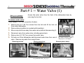
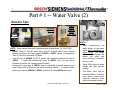
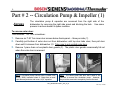
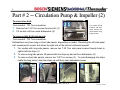
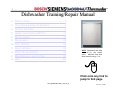
1
/
/
/
Dishwasher Training/Repair Manual
•
•
•
•
•
•
•
•
•
•
•
Water valves…………………………………..… 2
Circulation pumps & impellers……………… .4
Control modules………………………………. ..9
Heater assemblies & NTC’s………...……….. 13
Drain pumps……………………………………. 19
Dispensers……………………………………... 20
Door latches…………………………………… 23
Aqua sensors………………………..…...…… 24
Water fill assemblies…………………………. 25
Miscellaneous service tips………………….. 26
Quiz……………………………………………….28
NOTE: Dishwashers are rated
120V, 60 Hz, 15A, 1450W
(max.). Maximum amp draw
when heaters running ~ 11A.
Click onto any link to
jump to that page
702_58300000133621_ara_en_a
Rev 0 (1/17/08)
/
/
2
/
Part # 1 -- Water Valve (1)
Disassembly
Access the water valve from the front of the dishwasher base by
removing the toe kick.
To remove water valve:
Tools needed: T20 Torx screwdriver & pliers.
1. Remove two (2) T-20 Torx screws from toe kick and tilt toe kick out
Old style
valve
shown
from under dishwasher.
2.
3.
4.
5.
6.
Remove base insulation (on models with insulation).
Move sump inlet hose away from water valve (without disconnecting it).
Disconnect wires from water valve, including ground wire.
Remove two (2) T-20 Torx screws from water valve.
Pull valve out from dishwasher and disconnect water hose from rear of
valve. Remove any water from sump & base.
Removing toe kick
Moving sump hose
CONNECTION HINTS: Water
connection 3/8” NPT female.
Inlet water pressure range 5 120 psi (0.3 – 8.27 bars).
Removing hose clamp
Old style
valve shown
Old style valve shown
702_58300000133621_ara_en_a
Rev 0 (1/17/08)
3
/
/
/
Part # 1 -- Water Valve (2)
Service Tips
425458 &
189533
607335
“Rast 5”
580009
(yellow
stem) or
167081
(white stem)
HINTS:
NOTE: Water valves have been upgraded several times since 1st 1/4 of 1999.
• 607335 “Rast 5” time-fill water valve (UC/43 & above dw’s) has a keyed
terminal connector and can’t replace 425458 or 189533 valves. It replaces all
“Rast 5” time-fill or pressure-fill valves.
• Time-fill valve # 425458 (UC/42 & below) also replaces pressure-fill valve #
189533. It looks like pressure-fill valve # 189533, but isn’t the same.
Pressure-fill valves can’t replace time-fill valves.
• Pressure-fill valve (part # 189533) has a horizontally mounted solenoid and
water fitting held in place by the metal mounting bracket. It replaced older
pressure-fill valves (580009 & 167081) until time-fill valve 425458 was used.
702_58300000133621_ara_en_a
•
When reconnecting the
water supply to the water
valve, don’t overtighten the
elbow fitting. On valves
with vertical solenoids, the
plastic can crack and
cause leaking if excessive
force is used.
•
Using Teflon tape on water
fittings can help prevent
leaking.
•
The water valve can be
accessed without removing
outer door or base cover.
However, removing them
will provide easier access.
Rev 0 (1/17/08)
/
4
/
/
Part # 2 -- Circulation Pump & Impeller (1)
Access
The circulation pump & capacitor are accessed from the right side of the
dishwasher by removing the right side panel and blocking the tank. Use same
process to access heater & Apexx modules.
To remove outer door:
Tools needed: T20 Torx screwdriver.
1. Remove six T-20 Torx inner door screws below fascia panel -- three per side (1).
2. Carefully pull bottom of outer door out from dishwasher until top door tabs clear, then pull door
down until it releases from dishwasher (2). Take care to not scratch outer door.
3. Remove 1-piece foam or two plastic door guards (3). The plastic door guards occasionally fall out
when the outer door is removed.
1
2
NOTE: Circulation pump 239144 motor is rated 120V,
60 Hz, 160W, insulation class A. Motor has an autoreset thermal protector and uses a 10μF capacitor.
3
HINT: The fascia panel and door don’t need to be
removed to access the circulation pump. However,
they must be removed to completely remove the tank.
702_58300000133621_ara_en_a
Rev 0 (1/17/08)
/
/
5
/
Part # 2 -- Circulation Pump & Impeller (2)
To remove toe kick:
1 2
Tools needed: T20 Torx screwdriver.
For models UC/36
& above, toe kicks
screw directly into
plastic bases using
longer screws.
1. Remove two T-20 Torx screws from toe kick (1).
2. Tilt toe kick out from under dishwasher (2).
To remove right & left side panels:
Tools needed: T20 Torx screwdriver.
Dishwashers may have long or short side panels, depending on model. Removing the left side panel
isn’t necessary for access, but allows the right side of the tank to be blocked upward.
1. For models with long side panels, remove two T-20 Torx side panel screws through holes in
right & left trim strips (1).
2. To remove long side panels, lift panels with trim strips up and out from dishwasher (2).
3. To remove short side panels, remove two T-20 Torx screws (3). To avoid damaging trim strips
(while blocking tanks), slide trim strips up until they clear dishwasher bases.
1
Long
side
panels
shown
2
3
3
Long side
panels shown
Short side
panels shown
702_58300000133621_ara_en_a
Long side
panels shown
Short side
panels shown
Rev 0 (1/17/08)
/
/
6
/
Part # 2 -- Circulation Pump & Impeller (3)
To raise right side of tank for circulation pump access:
Tools needed: T20 Torx screwdriver and pliers.
1. Remove one T-20 Torx screw from both rear corners holding tank to base (1) -- removing screw
2.
3.
4.
5.
from both sides allows tank to be blocked upward.
Remove right toe kick bracket by removing T-20 Torx screw (2).
Remove T-20 Torx screws from front right bottom corner holding tank to base (3).
Remove right hinge cover (4a), release right door tension cord from hinge (4b) & remove ground
wire (4c).
Raise and block up tank as shown with strut onto base (5a), sliding a piece of wood or other solid
material between the tank and base to keep tank from falling back onto base (5b).
Screw
1
2
CAUTION:
Don’t turn dishwashers
upside-down for tank access.
When
dishwashers are turned upside-down,
water can flow into the water fill assembly
diaphragm and cause water to not fill
properly.
3
4a
4b
4c
5a
5b
702_58300000133621_ara_en_a
Rev 0 (1/17/08)
/
/
7
/
Part # 2 -- Circulation Pump & Impeller (4)
Disassembly
1.
2.
3.
4.
To remove motor to access impeller or change complete pump:
Tools needed: flat blade screwdriver.
Disconnect wire harness from motor after carefully noting connections (1).
For UC/11 & later models with softer bearing, lift up rubber straps from both sides of motor (2). For
older models, lift motor up from base.
To release plastic latch on pump/motor housing (@ 2:30 position), carefully push onto latch with
screwdriver (3).
To release motor from pump housing, twist motor to the right (clockwise). Some force may be
required. Capacitor should be ~ 11:00 position (4). Pull motor out from pump housing.
HINT:
When
replacing
circulation pumps for softer
bearing models (UC/11 & later),
reusing existing front pump
housings can save time by not
changing hose clamps.
If
desired, order # 172272 hose
clamps & replace entire pumps.
3
CAUTION:
Don’t grab
motor next to the capacitor
to avoid jamming your
hand on the capacitor.
See page 8 for
pump types.
1
3
4
2
4
Latch
702_58300000133621_ara_en_a
Rev 0 (1/17/08)
/
8
/
/
Service Tips -- Comparing Circulation Pump Versions
Depending on features, dishwashers have one of four types of circulation pumps. Pumps use different
controls, wire harnesses, heaters & sump filters, so replace with identical replacement pumps.
# 665510 BLDC pump
# 239144 pump
• Pump, motor and control come as one unit.
• Speed changes as needed for wash cycle
and washability (Vario wash).
• Pump is isolated from motor, so no seal is
needed and no need to loosen or replace
impellers
• Used starting with UC/46 index.
• Can buy # 266511
motor separately.
• Can use # 167085
impeller kit.
# 442548 (“Sicasym”) pump
• Most common pump. Used starting with UC/21 index. Smaller than 239144
pump.
• Used with control modules & single wire harnesses designed for Sicasym
pumps. Controls have motor starter software.
• Can’t use # 167085 impeller kit.
# 437345 pump for water switches
•
•
•
•
NOTE: Cheater cords
can’t be used to check
Sicasym and BLDC
pumps since they use
special starters.
More powerful for use with water switches (Apexx & ExactWash models).
Has separate motor starter (# 182318).
Must use with heaters with water switches & sumps with extra filter cylinder.
Can use # 167085 impeller kit.
702_58300000133621_ara_en_a
Rev 0 (1/17/08)
/
9
/
/
Part # 3 -- Control Modules
Disassembly
(SHU 9922 shown)
Control modules are easily removed from fascia
panels by bending console tabs.
Tools needed: T-20 Torx & flat blade screwdrivers.
1.
2.
3.
4.
Remove fascia panel by removing T-20 Torx inner door screws.
Disconnect wire harnesses from module after noting connector locations.
Pry out metal console tabs holding module to console.
Carefully pry back plastic tabs, then slide module from console.
Removing door screws
Removing fascia panel
Viewing control module
Check connections before
replacing modules!
Disconnecting wires
TIP: Modules have been replaced when problem was
loose connections. Before replacing modules, check
connections first!
Bending back tabs
Sliding module out
NOTE: Control modules for non-integrated models look
differently and have different tabs, but are removed using the
same procedure.
702_58300000133621_ara_en_a
Rev 0 (1/17/08)
/
10
/
/
Part # 3 – Apexx Control Modules
Disassembly
Apexx (SHV99A/SHX99A-B/SHY99A, DWHD94) control modules are
different than other models and are removed differently. Modules are
mounted on the base (where base wiring connectors were), not behind
fascia panels. This means:
• Dishwashers must be pulled out to change control modules.
• Dishwashers must be pulled out to measure voltages
resistances.
These instructions apply to
SHE/SHV/SHX98-99 models.
&
For access to Apexx control modules:
Tools needed: T-20 Torx screwdriver & pliers.
HINT: Apexx control
modules cannot be
checked
or
have
resistances measured
from the front of
dishwashers.
NOTE:
Modules were
moved to the base to make
room for the larger full text
displays in the fascia panel.
1.
2.
3.
4.
Remove outer door – see page 3.
Remove toe kick – see page 4.
Remove right/left side panels – see page 4.
Raise right side of tank – see page 5.
HINT:
Its helpful, but not
necessary, to remove outer
doors to access Apexx
control modules.
702_58300000133621_ara_en_a
HINT: It may be possible to reach
behind modules without blocking
up tanks. If not, then follow these
instructions to block up tanks.
Rev 0 (1/17/08)
11
/
/
/
Service Tips – Fault Codes & Control Coding
Controls contain codes for factory tests, customer service test program, dishwasher configuration and
fault codes. Consult test programs and fault codes for each dishwasher before using codes below.
P(X) Program codes
P0 = Functional test - used for assembly
P1 = Customer service test program
P3 = Endurance/Life test
P4 = Control coding (see “C(X)” control codes below)
E(X) Error codes
E0 = No errors
E1 = Heating error
E2 = NTC error
E3 = Filling error
E4 = Water switch cannot be positioned
E5 = Safety level reached
E6 = Aqua sensor error
C(X) Control Codes
Codes C1 to C9 possible, depending on dw model
HINT: Customers pushing Cancel-Drain or
Cancel-Reset buttons while dw’s are off
can see codes, leading to service calls.
702_58300000133621_ara_en_a
Rev 0 (1/17/08)
/
/
Service Tips -- Modules Displaying “1”
/
12
Occasionally dishwashers can run for hours, not finish washing & show a “1” in the display. This
means the module has timed out due to an unidentified heating problem -- all heating related parts
must be checked until the problem is found.
TIP: Modules have been replaced when
problem was loose connections. Before
replacing modules, check connections first!
START
If no, module is
working fine.
Has dishwasher
stopped
washing and is
showing a “1”
in the display?
NO
NOTE: The heating problem
must be fixed before the
module will reset and stop
showing a “1” in the display.
If yes, control module
has timed out showing
there’s an unidentified
heater problem.
3-winding circulation pumps can measure ~
7Ω or 9.4Ω, depending on motor starter.
Replacing NTC’s
also replaces HiLimit’s.
NTC
(~ 55kΩ
@72ºF)
YES
Control
module
(heater relay &
solder joints)
Circulation
pump
Wire
harness &
terminals
If flow switch is OK &
water doesn’t flow,
check circulation pump.
Flow Switch
(~ 0.4Ω)
702_58300000133621_ara_en_a
IMPORTANT:
Whenever a “1”
shows
in
the
module display,
the module must
be reset (after the
heating problem
has been fixed)
by running the
dishwasher. The
module
resets
after the 1st run.
Have these
parts been
checked??
Replacing heaters also
replaces NTC’s, flow
switches & Hi-Limit’s.
High Limit
(~ 0.3Ω)
Heater
(~ 11Ω)
HINT: Check module heater relays, wire
harnesses / terminals & heaters before
checking NTC’s, flow switches & high limits.
Rev 0 (1/17/08)
/
13
/
/
Part # 4 -- Heater & NTC (1)
Disassembly
The heater & NTC can be accessed or measured from the right side of the
dishwasher, but can only be removed by dropping the entire base (by flipping
the dishwasher on its back) since they are wedged underneath the tank.
For access to heaters & NTC’s:
Tools needed: T-20 Torx screwdriver & pliers.
1.
2.
3.
4.
Remove outer door – see page 3.
Remove toe kick – see page 4.
Remove right/left side panels – see page 4.
Raise right side of tank – see page 5.
HINT: The fascia panel and door don’t need to be
removed to access the heater & NTC. However, the door
must be removed to completely remove the tank.
HINT: Remove all water from the sump and hoses
before accessing the heater -- when the dishwasher is
flipped on its back, water can enter the water fill assembly
diaphragm and cause the dishwasher to not fill properly.
To separate base from tank (1):
1. Carefully lay dishwasher on its back.
2. Carefully pull door springs out from base.
Placing on back
Pulling out door springs from base & disconnecting cords
702_58300000133621_ara_en_a
Rev 0 (1/17/08)
/
14
/
/
Part # 4 -- Heater & NTC (2)
To separate base from tank (2):
3. Remove terminal blocks from base (for two-piece harnesses).
4. Disconnect hose from water valve (or remove water valve from base if easier).
5. Disconnect J-box ground wire, then pull wires out of J-box.
6. Pull out inlet hose from sump.
7. Carefully pull base away from tank and sump.
HINT:
Remove water
from sump and hoses
before laying dishwasher
on its back (to avoid
water entering water fill
assembly & causing
faulty water filling).
Old style
valve shown
Removing terminal blocks from base
Pulling J-box wires
Pulling out sump hose
Disconnecting hose from water valve
Pulling base carefully from tank & sump
702_58300000133621_ara_en_a
Rev 0 (1/17/08)
/
15
/
/
Part # 4 -- Heater & NTC (3)
To remove heater & NTC:
1. Remove two (2) T-20 Torx screws holding heater assembly to sump.
2. Disconnect wires from heater, flow switch, NTC & Hi-Limit after noting
connections.
3. Pull clips, then carefully pull heater assembly from sump & pump.
Note heater comes as an assembly (with housing & gasket).
NOTE: Softer bearing & nonsofter
bearing
heater
assemblies,
circulation
pumps and sumps cannot be
mixed and matched. Softer
bearing heaters don’t fit in
older models and older
heaters don’t fit in softer
bearing models.
HINT: If needed, use rinseaid to lubricate gaskets to
make it easier to assemble
heater to sump and pump.
Pull clips
Heater assembly
Removing heater screws Removing heater from sump/pump
HINT:
NOTE: Softer bearing & non-softer bearing heater assemblies are
connected to circulation pumps differently:
• Softer bearing models (UC/11 & above) have gasket assembled
to heater and have a separate hose clamp (order # 172272).
• Older models (UC/06) have a separate gasket and do not have a
hose clamp.
Hose clamp
“Softer
bearing” heater
702_58300000133621_ara_en_a
Heater
assemblies
contain
NTC’s, Hi-Limit’s &
flow switches (& aqua
sensors
where
applicable). If heaters
are replaced, these
parts are replaced too.
Rev 0 (1/17/08)
16
/
/
/
Service Tips -- Heater Troubleshooting Flowchart
Can also measure heater current
@ module red heater wire (~ 9.5A).
If ~ 11A, heater is
working fine.
With heater on
(during test
program), measure
dishwasher
incoming current
(black wire).
If ∞ , heater has
failed (opened).
Replace heater.
If ~11Ω, check high
limit, flow switch &
circulation pump.
If ~ 0, heater has
failed (shorted).
Replace heater.
NOTE: Flow through
heaters heat water ~
2ºF / minute.
Measure
voltage @
control
module.
If ~ 0 VAC, control
module (heater relay)
has failed. Replace
faulty module.
If ~120 VAC,
check heater
circuit.
TIP: Modules timing out &
displaying “1” means there’s an
unidentified heating problem.
Measure
resistance
@ heater
terminals.
If ~ 1.5A, heater
circuit has failed.
START
Measure high limit
& flow switch
resistance & check
circulation pump.
If high limit ~ 0.3Ω, flow switch ~ 0.4Ω &
circulation pump is OK, check wire
harnesses. Replace faulty harness.
702_58300000133621_ara_en_a
TIP:
If control
displayed
“1”,
reset it by running
the dishwasher.
If high limit, flow
switch or circulation
pump = ∞ , replace
faulty part.
Rev 0 (1/17/08)
/
/
Service Tips – Heater Operation
/
17
Seal
Flow through heater heats water without an exposed
tank element. Filtered water enters the heater from
the circulation pump. The heater heats water when
the flow switch signals water is present.
Heating element
NTC/Hi-limit
Flow
switch
Aqua
sensor
NTC
To upper
spray arm
Hi-limit
Heating
element
To upper
spray arm
To lower
spray arm
To lower
spray arm
Backflow
valve
Pump motor
Drain pump
cover
Drain pump
From circulation pump
Sump
Impeller Seal
The sump also contains an aqua sensor, drain pump,
NTC, Hi-limit and backflow valve. The aqua sensor
senses water cleanliness – dishwashers add rinses if
needed. The NTC senses water temperature. The Hi-limit
shuts off the heater if the water gets too hot. The backflow
valve prevents waste water from entering the dishwasher.
702_58300000133621_ara_en_a
Rev 0 (1/17/08)
18
/
/
/
Service Tips -- Water Switch (“Flow Control”)
Motor operated water switches are mounted underneath heater assemblies. They consist of a motorcontrolled disk (with 3 holes) which rotates and lines up over two sump ports (upper / lower spray arms) to
provide precise water control to upper, lower or both spray arms.
Microswitch
Cam
European disk shown,
which is different than
U.S. disk
Both spray arms
Upper spray arm
Lower spray arm
Disk
HINT: Models with water
switches & Top Rack Only use
water switches to divert water.
Separate
actuators
aren’t
needed.
Disk
Disk
To
upper
spray
arm
Disk
Water switch disk
To
lower
spray
arm
HINT:
Models with water
switches
need
stronger
circulation pumps (# 437345)
with separate motor starters (#
182318). Circulation pumps,
heaters & sumps for water
switch / non-water switch
models can’t be interchanged.
Water
switch disk
Heater
assy.
Water
switch
motor
TIP: Resistance at two
motor terminals ~ 1.5kΩ
702_58300000133621_ara_en_a
Rev 0 (1/17/08)
/
/
19
/
Part # 5 -- Drain Pumps
Drain pumps are mounted to sumps in the front of dishwashers -- they’re easily accessible from the front
of dishwashers by removing toe kicks.
To remove & install drain pump:
Tools needed: small flat blade screwdriver (for unlocking terminals).
• Remove toe kick/base cover, pull up terminal cover and
•
•
•
disconnect wires (using screwdriver to unlock locking terminals).
To remove pump, pull latch (on circular collar) & rotate pump
clockwise (cw). To install new pump, insert @ 2:00 position &
rotate counterclockwise (ccw).
Clean water & debris from base, then check float operation.
Connect wires, then install base cover & toe kick.
DRAIN HOSE INSTALLATION TIPS:
• Must have drain hoses with high loops (min. 20” high), even with air gaps *.
• Drain hoses can be up to 10’ long – can add up to 4’ to dishwasher hose.
• Secure drain hoses to rear of dishwashers with non-metal bands.
• Make sure drain hoses aren’t kinked.
• UC/43 & later drain pumps have (Rast 5) connectors, which aren’t
interchangeable with older pumps with spade terminals (listed below).
NOTE: Drain pumps in installations with
Johnson Tees (in Washington State) must
use stronger 4-vane pumps (# 184178).
Standard 9-vane drain pumps (# 167082)
are quieter and smoother than 4-vane
pumps. Older pumps had 6-vanes.
NOTE: Drain
pump is rated
120V, 60 Hz,
35W, 0.85A.
Drain pump
Water valve
* NOTE: High loops
are needed to prevent
cavitating.
TIP: Often improper
installations, not drain
pump issues, cause
dishwashers to not
drain properly.
702_58300000133621_ara_en_a
Latch
Terminals
Rev 0 (1/17/08)
/
20
/
/
Part # 6 -- Dispensers (1)
CAUTION:
Disassembly
Inner door
edges are sharp!
Cover
door edges and remove
dispenser carefully.
Disconnecting wire harness
Bending retainer tabs
HINT: To remove/install dispensers:
• Remove outer door, remove fascia panel & disconnect wire harness from fascia panel.
• Disconnect wire harness above dispenser, then remove wires to wax motor & sensor.
• Disconnect condensation tube (for older models with condensation tubes in doors).
• Remove any tape or wire ties. Bring replacement wire ties for reassembly.
• Bend retainer tabs, then push dispenser inward toward tank. Protect hand with towel
as inner door edges are sharp.
• Replace from inside of tank -- position O-ring seal and bend tabs to secure. Lubricate
O-rings with rinse-aid & support inner doors to avoid damage if O-rings stick.
702_58300000133621_ara_en_a
Bending
retainer tabs
Rev 0 (1/17/08)
/
/
21
/
Part # 6 -- Dispensers (2)
During each wash program, the wax motor opens twice, once to dispense detergent and again to
dispense rinse-aid. The wax motor opens the same -- linkages open the detergent door & operate the
rinse-aid dosage plunger. Dispensers can have reed switches or optical rinse-aid sensors.
Dosage plunger
Linkage
490472 shown
Optical
sensor
Magnetic
float
Wax
motor
Condensation
tube (older
vented
dispenser)
NOTE: The white plastic linkage opens the detergent dispenser door,
then cocks in place to dispense rinse-aid when the wax motor operates
again. After the 2nd operation, the linkage resets for the next wash.
HINT:
Optical dispensers
have different connections
and can’t be substituted for
reed switch dispensers. Note
431413 top load dispensers
also use solenoid actuators
instead of wax motors.
Reed
switch
Cable
guide
A wax motor heats wax, which expands
and pushes a plunger. When the wax
cools, a spring pushes the plunger back.
702_58300000133621_ara_en_a
Rev 0 (1/17/08)
/
/
22
/
Service Tips – Optical Sensor Dispensers
Optical and top-load dispensers measure rinse-aid levels with optical sensors instead of reed
switches.
Transmitter diode
Transmitter diode
Optical rinseaid sensor
Optical rinseaid sensor
Prism
Prism
Receiver
diode
With rinse-aid present, the optical
receiver senses a diffused light beam.
Receiver
diode
When rinse-aid has run out, the optical
receiver senses a strong light beam.
HINT:
Optical
dispensers
have
different connections
and
can’t
be
substituted for reed
switch dispensers.
¾
Cable guide
Standard dispenser
Top-load
dispenser
¾
NOTE:
Top-load and standard
dispensers are NOT interchangeable.
702_58300000133621_ara_en_a
Rev 0 (1/17/08)
/
/
23
/
Part # 7 -- Door Latches
Disassembly/
Installation
Other than occasional misalignment, the only door latch repairs will be
replacing microswitches. Older SHU43/53/68 dishwashers used door
latches with rods connecting them with on/off switches.
To disassemble door latches:
1.
Remove T-20 Torx fascia panel
screws from inner door.
2.
Lower fascia panel from door.
3.
Locate door latch in console.
4.
Bend out console metal tabs to
allow latch removal.
NOTE:
Use only latches
specified for each model.
Latches can have differing
closing forces, be suitable for
specific door seals & can have
child locks.
NOTE: Door latches for UC/14 & up models are different than UC/06 - UC/12 models
-- they cannot be interchanged. Must replace strike plate & door latch together.
Lower fascia panel
Door latch in console
Tabs (inner view)
702_58300000133621_ara_en_a
Remove panel screws
Bend out metal tabs
Rev 0 (1/17/08)
/
/
24
/
Part # 8 -- Aqua Sensors
The aqua sensor only affects energy usage, eliminating a pre-wash and/or pre-rinse cycle if water is
clean. Most customers won’t notice if an aqua sensor fails. It’s located on the rear of the sump and can
be reached through the left side of the dishwasher (after the left side panel is removed – see page 4). Its
not necessary to block up the tank to reach the aqua sensor.
Receiver diode
Tank
Sump
Water
Base
NOTE:
Aqua
sensors provide
~ 20% energy
savings.
Transmitter diode
HINT: To change out the aqua sensor, pull off the
connector and pull out the aqua sensor (toward the
rear of the dishwasher). The aqua sensor slides into
slots in the sump. Make sure the aqua sensor is
properly inserted into the slots.
NOTE: The Apexx Sensotronic 2 aqua sensor #
175340 is similar to standard aqua sensor # 165279,
except it has two (red & green) soil sensors. They
mount the same way, but are not interchangeable.
702_58300000133621_ara_en_a
Rev 0 (1/17/08)
/
/
25
/
Part # 9 -- Water Fill Assembly
The water fill assembly is easily accessed from the left side by just removing the left side panel (see
page 4). It can be a pressure-fill (with diaphragm) or time-fill, depending on model.
Diaphragm
Water fill switch
No diaphragm or water fill
switch on time fill models
Float
switch
Float
switch
Float
Float
Pressure-fill
Time-fill
HINT: Most water fill assembly repairs involve replacing
microswitches. Occasionally tank insulation or other
debris can prevent the diaphragm switch lever from
operating, allowing overfilling.
NOTE: Water inlet valves for time and pressure-fill
look the same, but pressure-fill valves can’t be used
on time-fill models. Presently, both pressure-fill and
time-fill models use time-fill valve 425458.
TIP: Floats should be checked and bases should be cleared of
water & debris whenever water fill assemblies are worked on.
702_58300000133621_ara_en_a
Rev 0 (1/17/08)
/
/
26
/
Miscellaneous Service Tips – Hinge Levers & Bushings
Since 12/15/03, all dishwashers have upgraded hinge levers and hinge bushings. New hinge levers
and bushings can’t be used with old bushings and levers – must replace levers and bushings together.
New 15mm hinge
bushing with latches
Hinge
Plate
Old 14mm
hinge
bushing
with lock
Hinge
Lever
Hinge
Bushing
Lock
Pulley
NOTE: New and old hinge levers and bushings can’t be mixed
and matched since new hinge levers have 15mm holes to fit new
hinge bushings and old hinge levers had 14mm holes for old hinge
bushings (and locks).
Old
Replacement Hinge Levers and Bushings
Left
Left
Left
Description
492033 Lever (14mm)
488250 Bushing (14mm)
263115 Lever + bushing
Replaced by
Lock
Description
494876 + 165296 Lever + bushing (15mm)
494876 + 165296 Lever + bushing (15mm)
(14mm)
494876 + 165296 Lever + bushing
Door
Spring
Bushing
New
Side Part #
Cord
(15mm)
Right 492034 Lever (14mm)
494875 + 165296 Lever + bushing (15mm)
Right 488250 Bushing (14mm)
494875 + 165296 Lever + bushing (15mm)
Right 263119 Lever + bushing (14mm) 494875 + 165296 Lever + bushing (15mm)
Latches
Remove old hinge
bushing locks by
inserting
small
screwdrivers into
the lock hole and
twisting them out.
TIP: Unlike old hinge bushings, new hinge bushings are
self-locking and don’t need separate locks. To remove
doors when new hinge bushings are used, spread latches
apart until door pins clear latches.
NOTE: When new 15mm hinge bushings (with latches)
are opened, replace them instead of reusing them.
702_58300000133621_ara_en_a
Rev 0 (1/17/08)
/
/
27
/
Miscellaneous Service Tips – FAQ’s (2)
•
Wood door spring usage chart – Once original door spring has been
identified (Orange 182640 or Violet 168568), use chart below to adjust
spring tensions:
Door Wood Panel Weight
Existing Door Less than 5.5 lbs (2.5
Spring
kg)
5.5 to 9 lbs
(2.5 to 4.1 kg)
9 to 15 lbs
(4.1 to 6.8 kg)
15 to 18 lbs
(6.8 to 8.2 kg)
18 to 21 lbs
(8.2 to 9.5 kg)
Change to 173696
Change to 168576 Blue
Yellow spring - use
spring - use tension
tension screw if needed
screw if needed
No action
Violet
(168568)
Use tension screw to
increase tension
Change to 182640
Orange spring - use
tension screw if needed
Change to 168576 Blue Change to 168568 Violet
spring - use tension
spring
screw if needed
No action
Orange
(182640)
Use tension screw if
needed to increase
tension
Use tension screw to
increase tension
702_58300000133621_ara_en_a
Rev 0 (1/17/08)
28
/
/
/
?? Dishwasher Service Pop Quiz ??
1.
A high loop in the drain hose must be used in installations with air gaps
(T/F).
2. A cheater cord can be used to check all circulation pumps (T/F).
3. All dishwashers have a control module mounted in the top of the door (T/F).
4. A dishwasher showing a “P” or “C” code after installation is faulty from the
factory and must be exchanged (T/F).
5. One water valve can be kept on your truck for all replacements (T/F).
6. Any time a dishwasher runs for several hours or times out, the problem will
be solved if the control module is replaced (T/F).
7. Match each circulation pump with it’s starter:
a) Pump # 239144
a) PTC motor starter
b) Pump w/ water switch # 437345
b) 3-phase motor starter
c) Sicasym pump # 442548
c) Software in main control
d) BLDC pump # 665510
d) Start capacitor w/ cutout switch
8. If a door latch is on backorder, another type can be used (T/F).
9. Aqua sensors don’t have to be replaced if they fail (T/F).
10. Drain pumps have changed little over the years and are interchangeable
with all dishwasher models (T/F).
702_58300000133621_ara_en_a
Rev 0 (1/17/08)
29
/
/
/
?? Dishwasher Service Pop Quiz ?? Answers
1.
A high loop in the drain hose must be used in installations with air gaps
(T/F).
Not Sicasym,
2. A cheater cord can be used to check all circulation pumps (T/F). BLDC
3. All dishwashers have a control module mounted in the top of the door (T/F).
4. A dishwasher showing a “P” or “C” code after installation is faulty from the
factory and must be exchanged (T/F). Exit control coding mode
5. One water valve can be kept on your truck for all replacements (T/F).
6. Any time a dishwasher runs for several hours or times out, the problem will
be solved if the control module is replaced (T/F). Check heater system
7. Match each circulation pump with it’s starter:
a) Pump # 239144
a) PTC motor starter
b) Pump w/ water switch # 437345
b) 3-phase motor starter
c) Sicasym pump # 442548
c) Software in main control
d) BLDC pump # 665510
d) Start capacitor w/ cutout switch
8. If a door latch is on backorder, another type can be used (T/F).
9. Aqua sensors don’t have to be replaced if they fail (T/F).
10. Drain pumps have changed little over the years and are interchangeable
with all dishwasher models (T/F). Rast 5 connector starting UC/43
702_58300000133621_ara_en_a
T
F
F
F
F
F
F
T
F
Rev 0 (1/17/08)