1
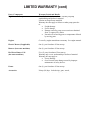
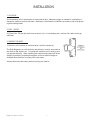
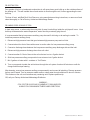
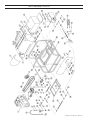
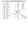
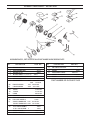
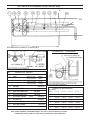
Pressure Washers
and Accessories
COBALT SKID - CUSTOM
P/N: CUSTOM4040H
& 3040H (C983040H)
Operators Manual
and Parts Book
Delco Pressure Washers - PN LIT-COBALT-DEL Rev. 7-08
LIMITED WARRANTY
At DELCO® CLEANING SYSTEMS, we distribute top quality industrial / commercial / personal pressure
washers that are designed for heavy-duty use, maximum reliability, durability, and long life. Our pressure
washers are built for all duty applications and steady use due to higher quality levels.
The manufacturer of this product agrees to repair or replace designated parts that prove defective within the
warranty period of one (1) year listed in the chart. Specific limitations/extensions and exclusions apply,
and are listed in the chart on page 3. This warranty covers defects in material and workmanship and not parts
failure due to normal wear; abuse; accidental damage; negligence; improper use, maintenance,
and storage. To make a claim under the terms of the warranty, all parts said to be defective must be available
or returned (if requested) to DELCO® CLEANING SYSTEMS designated Warranty Service Center for
warranty inspection. The judgments and decisions of the Warranty Service Center concerning the validity of
warranty claims are final.
These warranties pass through to the end user. As a factory authorized and trained Warranty Service Center
the factory will honor the terms of all component warranties and satisfy claims of the appropriate warranty
provisions.
Normal wear items include, but are not limited to, Valves and Seals, which are not covered by this warranty.
This Warranty replaces all other warranties, express or implied, including without limitation any warranties of
merchantability or fitness for a particular purpose and all such warranties are hereby disclaimed and excluded
by the manufacturer. The Manufacturer’s warranty obligation is limited to repair and replacement of defective
products as provided herein and the Manufacturer shall not be liable for any further loss, damages, or
expenses – including damages from shipping, accident, abuse, acts of God, misuse, or neglect. Neither is
damage from repairs using parts not purchased from the manufacturer or alterations performed by non-factory
authorized personnel. Failure to install and operate equipment according to the guidelines put forth in the
instruction manual shall void warranty.
This warranty does not cover the following: damage resulting from shipping (claims must be filed with freighter),
accident, abuse, act of God, misuse, or neglect. Neither is damage from repairs or alterations performed by
non-factory authorized personnel or failure to install and operate equipment according to the guidelines put
forth in the instruction manual.
The manufacturer will not be liable to any persons for consequential damage, for personal injury, or for
commercial loss.
LIMITED WARRANTY (cont)
Parts / Components
High Pressure Pumps
Warranty Period and Details
Five (5) year limited manufactuer warranty on pump
workmanship and defects in material.
Lifetime on forged brass manifold.
Warranty does not apply to failures on other pump parts due
to:
• Freight damage
• Freeze damage
• Damage caused by parts or accessories not obtained
from / or approved by Delco
• Normal wear of moving parts or components affected
by moving parts.
Engines
Covered by engine manufacturer warranty. See engine manual.
Electric Motors (if applicable)
One (1) year from date of first start up.
Burners (hot water machines)
One (1) year from date of first start up.
Hot Water Burner Coil
(hot water machines)
Five (5) years from date of first start up.
Warranty only covers workmanship or defects of material.
Warranty does not apply to:
• Freeze Damage
• Over Pressure burst damage caused by improper
maintenance of safety devices.
Frame
One (1) year from date of first start up.
Accessories
Ninety (90) days. Includes tips, guns, wands,
injectors, unloaders, hose reel, brushes, foamers,
Table of Contents
Operator Safety Instructions . . . . . . . . . . . . . . . . . . . . . . . . . . . . . . . . . . . . . . . . . . . . . . . . . . . . 5 - 6
Installation . . . . . . . . . . . . . . . . . . . . . . . . . . . . . . . . . . . . . . . . . . . . . . . . . . . . . . . . . . . . . . . . . . . 7
Machine Operation Instructions. . . . . . . . . . . . . . . . . . . . . . . . . . . . . . . . . . . . . . . . . . . . . . . . . . 8 - 9
Maintenance of Components . . . . . . . . . . . . . . . . . . . . . . . . . . . . . . . . . . . . . . . . . . . . . . . . . 10 - 12
Diagnosis and Maintenance . . . . . . . . . . . . . . . . . . . . . . . . . . . . . . . . . . . . . . . . . . . . . . . . . . . . . 13
Components Locators . . . . . . . . . . . . . . . . . . . . . . . . . . . . . . . . . . . . . . . . . . . . . . . . . . . . . . 14 - 21
TS2021 Pump Component Locator and Parts List. . . . . . . . . . . . . . . . . . . . . . . . . . . . . . . . . 22 - 25
Series Unloader Valve Component Locator and Parts List . . . . . . . . . . . . . . . . . . . . . . . . . . . 26 - 27
12V Electrical Schematic . . . . . . . . . . . . . . . . . . . . . . . . . . . . . . . . . . . . . . . . . . . . . . . . . . . . . . . 28
Burner Component Locator and Parts List . . . . . . . . . . . . . . . . . . . . . . . . . . . . . . . . . . . . . . . . . . 29
Gun and Hose Assembly Component Locator and Parts List . . . . . . . . . . . . . . . . . . . . . . . .
4
30 - 31
Cobalt 5 3 0 0 O w n e r ’ s M a n u a l
IMPORTANT SAFETY PRECAUTIONS
IMPORTANT:
Please read the following instructions before installing and operating this equipment.
DANGER
THIS EQUIPMENT CAN BE HAZARDOUS TO OPERATOR SAFETY AND ONLY AUTHORIZED PERSONNEL WHO HAVE READ AND UNDERSTAND THE INSTALLATION AND OPERATION MANUAL SHOULD
BE PERMITTED TO OPERATE THIS EQUIPMENT. DO NOT LEAVE WAND UNATTENDED WHILE
EQUIPMENT IS RUNNING.
Failure to follow all cautionary warnings and procedures may result in serious or fatal injury and/or property
damage including, but not limited to: fire, severe burns, concussion from explosion, electrocution, scalding,
penetration by pressurized water, chemical reaction, asphyxiation, cuts, contusions, laceration, and loss of
body parts and/or life.
DO’S
1 . ALWAYS WEAR SAFETY GLASSES, GOGGLES or FULL FACE SHIELD; GLOVES, and when spraying
acids WEAR RAIN GEAR. NEVER RUN ACIDS THROUGH THE PUMP ON THIS EQUIPMENT.
2. USE ONLY THE SAME SIZE NOZZLE SUPPLIED WITH THIS EQUIPMENT.
3. CHECK YOUR BATTERY FOR WATER LEVELS AND MAINTAIN A GOOD CHARGE.
4. USE 3⁄4" (inch) x 50' (foot) GARDEN HOSE FOR WATER SUPPLY-.
5. USE A CLEAN FUEL CAN FOR REFUELING UNIT.
6. USE CLEAN DIESEL FUEL OR KEROSENE. NO ADDITIVES. Fill fuel tank each evening. This will help
minimize condensation in fuel tank, and prolong fuel pump life.
7. Always follow chemical manufacturer’s recommendations in use of chemicals with this equipment.
Immediately after using chemical solutions through this equipment, flush thoroughly with clear water.
8. Disconnect all electrical power before performing any maintenance on this equipment.
9. Make sure positive is always positive and negative is always negative to keep from shorting out.
10. When storing this equipment in freezing weather conditions, this equipment must be drained thoroughly;
and the plumbing system charged with a 50% solution of permanent type antifreeze. Antifreeze should
be used when the equipment is not in service for prolonged periods or is being transported in freezing
weather. NOTE: Antifreeze must be flushed out of equipment thoroughly before any cleaning project
begins. Failure to do so could result in damage to paint or chemical attack on painted surfaces.
11. Use a water softener on your water system if it is high in mineral content (HARDNESS). Failure to do so
will result in lime build-up in plumbing systems.
12. Use only manufacturer approved components when replacing parts on this equipment. Failure to do so
may create operating conditions that are hazardous to personal health, safety, and will void the warranty.
13. Use only recommended oil in pump.
14. Always cool down coil.
Cobalt 5 3 0 0 O w n e r ’ s M a n u a l
5
DO NOT’S
DO NOT - UNDER ANY CIRCUMST ANCES - POINT THE HIGH PRESSURE NOZZLE
AT YOURSELF , OTHER PEOPLE, OR
ANIMALS!
1. DO NOT use an undersized discharge nozzle.
2. DO NOT disconnect the pressure hoses or wand while the equipment is HOT, PRESSURIZED or RUNNING.
3. DO NOT operate this equiopment without sufficent water supply to the pump.
4. DO NOT operate this equipment without proper ventilation or in a closed space.
5. DO NOT use any type of fuel other than # 2 diesel, kerosene or # 1 home heating oil.
6. DO NOT leave wand unattended while equipment is running.
7. DO NOT point the stream of water from nozzle toward any person or animal (including the operator).
8. DO NOT touch exhaust stack, metal wand and hose on HOT WATER UNIT
. THEY GET VERY HOT!
9. DO NOT obstruct the exhaust stack.
10. DO NOT run engine or burner within 25 feet of flammable meterials or dust.
11. DO NOT use this equipment around or near explosive enviroment of any kind.(Gas, paint, solvents, etc.)
12. DO NOT screw the pop-off vavle all the way in to prevent leaking or dripping.
13. DO NOT adjust the unloader-regulator valve (on trigger control units) to a pressure in excess of 200 PSI
of equipments motor or pump rating.
14. DO NOT secure trigger gun in the open position (ON). Operate ONLY with your hand during operation
to prevent injury.
15. DO NOT
allow air into the water system through soap valve or loose fittings.
16. DO NOT operate the machine if the water pressure drops or is low.
17. DO NOT continue to operate this machine if burner fails to shut off when trigger is released (closed).
18. DO NOT continue to operate this machine if burner fails to light.
19. DO NOT smoke or operate this machine while filling or emptying fuel tank(s), or connecting/disconnecting tanks and fittings.
20. DO NOT operate this machine if coil becomes clogged or sooted.
21. DO NOT alter machine from manufacturer’s design.
22. DO NOT attempt to pull beyound normal lenght.
23. DO NOT attempt to service this machine without first disconnecting the electrical service. Failure to do
so may cause severe or fatal electrical shock.
24. DO NOT BY-PASS ANY SAFETY DEVICE ON THIS MACHINE!
25. DO NOT USE ANY TYPE OF INSECTICIDE, TOXICS, OR ACID THAT PRODUCE TOXIC FUMES, OR
USE ONL Y
EXPLOSIVE MATERALS IN THE SOAP SUCTION SYSTEM OF THIS EQUIPMENT.
DETERGENTS PROVEN SAFE FOR HUMAN CONT
ACT .
6
Cobalt 5 3 0 0 O w n e r ’ s M a n u a l
INSTALLATION
1. LOCATION Avoid operating units in small areas or near exhaust fans. Adequate oxygen is needed for combustion or
dangerous carbon monoxide will result. Stationary units should be installed in accordance with local plumbing and heating codes.
2. FUEL SUPPLY Oil Fired Units: Fill fuel tank with clean kerosene, No. 1 home heating fuel, or diesel fuel (without anti-gel
additives.)
3. VENTING THE UNITS If the unit is to be used in an enclosed area it must be vented out.
The Draft Regulator (on oil-fired units) and chimney must be same size as
the stack on the cleaner unit. Poor draft will cause the unit to soot-up and
not operate efficiently. When installing the machine so the stack will be as
straight as possible, protruding through the roof at a sufficient height to
eliminate down-draft and to comply with local codes.
Always disconnect the battery when servicing your cleaner.
Cobalt 5 3 0 0 O w n e r ’ s M a n u a l
7
OPERATING THE MACHINE
PRE-OPERATING INSTRUCTIONS
1. Connect the swivel end of the discharge hose to the cleaning gun.
2. Attach the hose to the machine outlet.
3. Check the fuel level in the fuel tank. Add fuel if required. It is best to keep fuel tank full during nonworking conditions.
4. Attach an ordinary garden hose to the float tank inlet. Turn on the water supply and let the float tank fill.
5. Connect the power cord to an adequately wired and grounded electrical source.
6. Place the end of the soap line into your soap solution container.
OPERATING INSTRUCTIONS
NOTE: On initial start up, or if machine has not been operated for several days, it is advisable to remove
the nozzle from the cleaning gun and flush out any foreign material. Turn the switch to position 1 (pump)
and let the unit run until clear water flows through the cleaning gun.
1. Turn on the water supply.
2. Add fuel if required. Check oil levels in pump and engine before starting.
3. Install the nozzle tip into the cleaning gun.
4. Close the soap valve. (turn fully clockwise)
5. Securely hold the cleaning gun and turn the switch to position 1(pump).
6. The recommended method of cleaning is:
A. Wet entire surface and remove the loose dirt with water only,
B. Turn on the soap by opening the soap valve (turn the handle counterclockwise). NOTE: The operating pressure of the machine will drop to nearly zero until the soap line is primed.
C. Cover the entire surface to be cleaned with soap/water solution by applying from the bottom up.
Allow the soap to stay on surface four to five minutes.
D. Close the soap valve and wash at high pressure with water only from the top down.
NOTE:
Soap will flush from the coil and discharge hose within a minute or two of operation.
E. For hot water washing, turn the switch to position 2 (burner). CAUTION: If there is a sudden loss of
pressure while washing with hot water, turn the burner off immediately and attempt to locate the
problem while running cold water only. Failure to turn the burner off could cause excessive temperature and pressure build-up in the heating coil.
8
Cobalt 5 3 0 0 O w n e r ’ s M a n u a l
SHUT DOWN INSTRUCTIONS
1. If the burner is on turn control switch to position 1(pump).
2. Run water through the pump until cool water flows from the cleaning gun. Failure to do this could result
in increased coil scaling.
3. Turn the control switch to off.
4. Turn off the water supply.
5. If the machine will be exposed to freezing temperatures, see winterizing procedure.
THINGS TO CHECK DAILY
1. Check oil level in pump.
2. Fill fuel tank at the end of each day’s use to prevent condensation build-up in fuel system.
3. Fill soap container.
4. Check oil level in engine.
THINGS TO CHECK WEEKLY
1. Check and clean water float tank and pump inlet screen.
2. Check all hoses for leaks and damage. Repair or replace as needed.
3. Check pressure nozzle for wear. Replace if needed.
4. Check all nuts and bolts. Tighten as needed (DO NOT OVER TIGHTEN.)
5. Check all water connections for leaks. Tighten if loose.
7. Check belts and pulleys for wear and tightness. (DO NOT CHECK WHILE MACHINE IS RUNNING.)
Cobalt 5 3 0 0 O w n e r ’ s M a n u a l
9
MAINTENANCE OF COMPONENTS
PUMPS
1. Refer to pump section in this manual for your model of equipment.
2. Change pump oil after the first 25 hours of use. Subsequent changes should be every 250 hours or 3
months, whichever comes first.
A. Disconnect power supply.
B. Remove drain plug on pump and drain oil.
C. I f the oil has water in it, it is important to flush out the pump with oil before refilling pump with the
proper oil.
3. Refilling: Replace drain plug and fill slowly to the dot in the center of sight glass, or th the proper level on
dip stick. Do not over fill.
4. Use a high quality 30 wt. non-detergent oil.
OIL BURNERS
1. BLOWER FAN: Clean blower fan in burner housing once a year or as often as needed. Dirt and deposits
will reduce air delivery and affect combustion.
2. FUEL NOZZLE: Keep tip free of surface deposits wiping with a clean, solvent saturated, cloth rag. The
nozzle should be changed once a year for maximum heating and emision control.
3. FUEL FILTER: Clean or replace every 400 hours or 3 months, whichever comes first (or as needed).
This will help prolong fuel pump life and burner efficiency.
DESCRIPTION
Racor Water Separator
4. FUEL TANK: Drain one pint of fuel from bottom of fuel tank every 50 hours of use or every two weeks,
whichever comes first. Check for water or contaminates in fuel. If any are present, drain and flush fuel
tank then refill with clean fuel. This will prolong fuel pump life and burner efficiency.
5.
ELECTRODES: Clean off carbon deposits on electrodes. To adjust elctrodes refer to figure and these
instructions:
A. TO REMOVE THE GUN ASSEMBLY: Disconnect the oil
line at the burner fan housing. Remove gun holding nut
on outside of housing. Loosen transformer hold-down
screw and swing open transformer on hinges. Gun assembly can now be removed by turning 1/4 turn and lifting
out and pulling down through this opening.
B. SPACING OF ELECTRODES: The electrodes should be
spaced 1/8 inch apart, 5/16 inch above the top of fuel
nozzle and 1/4 inch from the center of fuel nozzle tip, to the electrodes.
10
Cobalt 5 3 0 0 O w n e r ’ s M a n u a l
6. FUEL PUMP: To bleed air out of fuel pump, open air bleed valve on side of fuel pump. Turn machine
and burner ON. When fuel looks clear (NOT FOAMING), close air bleeding valve. Air is out of fuel lines
and fuel pump.
A. To check fuel pressure, plumb a 200 PSI guage into the port marked gauge. DO NOT USE BLEED
VALVE PORT TO CHECK FUEL PUMP PRESSURE.
B. To adjust fuel pressure, insert a small flat screwdriver into pressure regulator slot and turn clockwise
to increase pressure and counter clockwise to decrease pressure. One full turn is about 10 PSI.
Use a pressure gauge. normal operating pressure is 140 PSI. DO NOT EXCEED 150 PSI.
C. Service the fuel pump once every 50 hours or 3 mnths by cleaning the fuel strainer screen. A
clogged strainer or fuel filter will cause fuel pump stravation and dry the fuel pump up. The ONLY
lubrication the fuel pump has is the fuel that runs through it. KEEP IT CLEAN for longer fuel pump
life.
WINTERIZING
1. Shut off and disconnect the water supply.
2. Drain float tank.
3. Install antifreeze kit (available through local dealer.)
4. Remove nozzle from wand, and insert pick up hose and soap line into a bucket of 50% solution of
antifreeze. Pump antifreeze throgh machine. Open and close trigger gun a few times to winterize
unloader system. When antifreeze flows from the wand, shut the pump off. Disconnect antifreeze kit.
NOTE: BEFORE
attempting to wash ANY painted surface, pump anti-freeze out of machine into a clean
bucket and save for next use.
Cobalt 5 3 0 0 O w n e r ’ s M a n u a l
11
DE-SOOTING COIL
Poor grades of fuel oil or inadequate combustion air will cause heavy soot build up on the outside surface of
the heating coil. This will insulate the coil and restrict air flow through the coil, further aggravating the soot
build up.
To clean off soot, add Red Devil Soot Remover, using manufactures mixing instructions, or remove coil and
clean thoroughly, or Call a Factory Authorized AAdvantage Dealer.
DE-LIMING OR DE-SCALING OF COIL
In hard water areas, or when using the wrong kind of soap, lime build-up inside the coil pipe will occur. Lime
build-up will decrease the water temperature, water flow may eventually plug the coil.
It is recommended that a low pressure auxiliary pump be used if de-liming or de-scaling is needed. To
install low pressure auxiliary pump.
1. Disconnect high pressure hose that goes between high pressure pump and coil inlet.
2. Connect about four feet of hose with screen to suction side of a low pressure auxiliary pump.
3. Connect a discharge hose between the low pressure auxiliary pump discharge side and the inlet.
4. Disconnect high pressure discharge hose from coil outlet.
5. Connect another 5-6 feet of hose to the coil outlet and run to a 5 gallon bucket.
6. Stick low pressure auxiliary pump suction hose w/screen into 5 gallon bucket.
7. Mix 2 gallons of water with 1 container of Coil Doctor.
8. Turn on pump and circulate the acid mixture through the coil system for about 40 minutes or until discharge solution stops foaming.
After cleaning, remove low pressure auxiliary pump assembly and connect all plumbing. Remove pressure
tip from end of wand. Turn on pressure washer and run clean water through machine for about 5 minutes.
This flushes out the coil and neutralizes any remaining acid. Replace pressure tip.
OR, call your Factory Authorized AAdvantage Distributor.
WARNING :
COIL DOCTOR IS ACID AND IS HARMFUL TO SKIN AND EYES.
ALWAYS FOLLOW MANUFACTURERS LABEL DIRECTIONS.
12
Cobalt 5 3 0 0 O w n e r ’ s M a n u a l
DIAGNOSIS AND MAINTENANCE
PROBLEM
Low Pressure
Pulsation, pump runs
extremely rough, pressure low .
PROBABLE CAUSE
SOLUTION
Worn nozzle
Replace nozzle of proper size.
Belt slippage.
Tighten or replace; use correct belt.
Air leak in inlet plumbing.
Use PTFE liquid or tape.
Pressure gauge inoperative or not
registering accurately.
Check pressure with new guage and replace as needed.
Relief valve stuck partially plugged or
improperly adjusted.
Clean and reset relief valve to system pressure
and correct by-pass. Check supply tank for contamination.
Worn seat or valves.
Clean or replace with valve kit.
Inlet suction strainer clogged or
improprly sized.
Use adequate size for inlet pump connection
and fluid being pumped. Clean frequently.
Worn seals. Abrasives in pumped
fluid, severe cavitation; inadequate
water supply, stressful inlet conditions.
Install and maintain proper filter, check line
size and flow available to pump. Install a C.A.T.
Fouled or dirty inlet or discharge valves.
Clean inlet and discharge valve assemblies.
Worn inlet or discharge valves.
Replace with valve kit.
Leaky discharge hose.
Replace hose. Check connections.
Faulty Pulsation Dampener
Check precharge (should be 30-50%) of system
pressure or replace as needed.
Restricted inlet or air entering inlet plumbing.
Check filters and clean as needed. Check fittings and use
PTFE liquid or tape for air tight connection.
Stuck inlet or discharge valve
Clean or replace valve. Check supply tank for contamination.
Water leakage from under
the manifold
Worn seals.
Replace with seal kit, check inlet pressure and system
temperature, use Thermo Valve in by- inlet pressure regulator
in inlet line.
Oil leak between crankcase
and pumping section *Slight leakage.
Worn crankcase seals.
Replace crankcase seals
Oil leaking in area of crankshaft
Worn crankshaft seal
Bad bearing .
Replace damaged seals.
Replace bearing.
Excessive play in the end of
the crankshaft.
Worn bearing .
Replace bearing.
Water in crankcase
inside of the crankcase
Humid air condensing into water.
Change oil every 3 months or 500 hours intervels using
premium grade 10W30 Non-detergent hydraulic oil,
(other approved oil every month or 200 hours.)
Leaking of crankcase seals or
seals installed backward.
Replace seals. Follow proper installation procedure.
Contact Cat Pumps supplier for crankcase servicing.
Oil leaking at the rear portion
of the crankcase
Damaged or improperly installed oil guage,
crankcase cover, or drain plug o-ring.
Replace oil gauge, crankcase cover or drain plug o-ring.
Thread in oil guage and drain plug hand tight to avoid
extruding o-ring.
Loud knocking noise in pump
Pulley loose on crankshaft.
Check key and tighten screw.|
Worn bearing, connecting rod or crankshaft.
Consult Cat Pumps supplier for crankcase servicing.
Stressful inlet conditions.
Install C.A.T.
Cracked or scored plungers
Abrasive material in the fluid being pumped
Check supply tank for contamination.
Replace plungers
Install proper filtration on pump inlet plumbing.
Excessive pressure and/or temperature
of fluid being pumped.
Check pressure and fluid inlet temperature; be sure they are
within specified range.
Over pressure of inlet or discharge
Reduce pressure per specifications.
Running pump dry.
DO NOT RUN PUMP WITHOUT WATER!
Frequent or premature failure
of the packing
Strong surging at the inlet
and low pressure at the discharge side.
Cobalt 5 3 0 0 O w n e r ’ s M a n u a l
Foreign particles in the inlet or discharge
Check for smooth surfaces on inlet and discharge valve seats.
valve or worn inlet or discharge valves.
Replace with kit if pitted or worn. Check supply tank for
contamination, Install and regularly clean filter. Do not pump
abrasive fluids.
13
SKID COMPONENT LOCATOR
14
Cobalt 5 3 0 0 O w n e r ’ s M a n u a l
SUPERSKID COMPONENT LOCATOR PARTS LIST
Ref. No.
Qty.
Part No.
Description
1
2
3
N/S
4
5
6
7
8
9
10
11
12
13
14
N/S
15
N/S
16
17
18
19
20
21
22
23
24
25
26
27
28
29
30
32
33
34
35
35A
36
37
N/S
38
39
40
41
42
43
44
45
46
47
1
1
1
1
1
2
1
1
4
4
3 FT.
1
1
1
1
1
1
1
1
1
1
1
1
1
1
1
1
1
1
1
1
2
1
1
1
1
1
1
1
1
1
2
1
3
2 FT.
1
1
3 FT.
2
2
1
GX390
TS1811
D209
D034
D026
D150
T353
W130
F010
S063
H012
C001
F001
T336
X007
T114
T239
T013
T335
T366
V038
T230
T002
C004
F046
F189
F381
F044
F187
F034
F048
F127
S019
V048
F129
F222
H007
H004
S024
K-7
T240
F125
F026
S064
H011
F043
F023
H008
F019
F005
F008
13 HP HONDA W/ ELEC. START ENGINE
PUMP
ENGINE PULLEY, 2TB36
ENGINE BUSH, P1X1
PUMP PULLEY, 2BK90H
PUMP, V-BELT, B/BP42
BURNER HOOD
BURNER, 12VDC (WAYNE BURNER)
1/4 X 1/4 IN. HOSEBARB
1/4 IN. HOSE CLAMP
1/4 IN. NYLON BRAID HOSE
FUEL FILTER
1/4 IN. BRASS STREET ELBOW 90°
BURNER FUEL TANK
CAP, FUEL CHROME
BURNER HEAD WITH INSULATION
COIL AND TANK ASSEMBLY
COIL W/ INSULATION
FLOAT TANK, S.S.
FLOAT TANK LID, S.S.
FLOAT VALVE
FLOAT ROD 1/4 IN. BRASS
FLOAT BALL
3/8 IN. SCREEN
HOSEBARB, 3/8 IN. X 5/8 IN. DRILLED
1/2 IN. BRASS STREET ELBOW, 90°
1/2 IN. X 12 IN. GALVANIZED NIPPLE
GARDEN HOSE CONNECTION S1
SCREEN AND O-RING
3/8 IN. MALE QUICK CONNECT
3/8 IN. X 1/2 IN. BUSHING
1/2 IN. TEE F.S. 3000#
HI-TEMP SWITCH
PRESSURE RELIEF VALVE RV500B
1/2 IN. X 4 GALV. NIPPLE
1/2 GALV. 90° ELL SCH. 80
3/8 IN. X 15 IN. HIGH PRESSURE HOSE
3/8 IN. X 26 IN. HIGH PRESSURE HOSE
PRESSURE SWITCH
UNLOADER VALVE
TANK, GAS 3005 SKID MS
3/8 IN. GALV. 90° EL SCH. 120
3/8 IN. X 3/8 IN. HOSE BARB
5/8 IN. HOSE CLAMP #6
3/8 IN. NYLON BRAID HOSE
3/8 IN. BRASS STREET EL. 90°
5/8 IN. X 3/8 IN. HOSEBARB
5/8 IN. NYLON BRAID HOSE
5/8 IN. X 1/2 IN. HOSEBARB
1/2 IN. CLOSE NIPPLE, SCH. 80
1/2 X 1/4 BRASS BUSHING
Cobalt 5 3 0 0 O w n e r ’ s M a n u a l
15
SUPERSKID COMPONENT LOCATOR
16
Cobalt 5 3 0 0 O w n e r ’ s M a n u a l
SUPERSKID COMPONENT LOCATOR PARTS LIST
Ref. No.
48
49
50
51
52
53
54
55
56
57
58
59
60
61
62
63
64
65
66
67
68
69
70
72
73
N/S
N/S
N/S
N/S
Qty.
Part No.
1
1
1
1
8 FT.
1
1
1
8
28
1
1
1
1
3
1
1
1
2
1
1
1
1
1
1
4
4
4
11
F001
F234
V032
F010
H012
V017
T441
T499
M010
F119
T498
N/A
S217
S040
N005
F011
F006
F196
F064
F066
F182
Cobalt 5 3 0 0 O w n e r ’ s M a n u a l
Description
1/4 IN. BRASS STREET EL. 90°
1/4 CLOSE NIPPLE, SCH. 80
1/4 IN. METERING VALVE
1/4 IN. X 1/4 IN. HOSEBARB
1/4 IN. NYLON BRAID HOSE
1/4 IN. SOAP CHECK VALVE
FRAME
SUB-FRAME
MOTOR MOUNT
5/16 HEX NUT
CONTROL PANEL, S.S.
UNLOADER BRACKET
BURNER LIGHT
BURNER SWITCH, 15 AMP.
GROMMET
n/a
n/a
n/a
1/2 IN. GALV EL. 90°. SCH. 40
1/2 IN. GALV. TEE, SCH. 40
TRIGGER GUN
WAND, 48 IN.
1/4 IN. FEMALE SOCKET Q.C.
3/8 IN. X 50 FT. 4000#SP
3/8 IN. FEMALE PLUG
5/16 IN. X 1-3/4 IN. BOLT
5/16 IN. X 1 IN. BOLT
5/16 IN. X 1-1/2 IN. BOLT
5/16 IN. X 3/4 IN. HHSMS
17
SKID COMPONENT LOCATOR
Ref. No.
1
4
18
19
36
37
44
50
81
103
Qty.
1
1
1
1
1
1
1
1
1
1
1
1
1
1
1
1
1
Part No.
T316
T114-SS
B004-SS
B008-SS
B002-SS
B007-SS
T706
T499-GEN-SS
T089-SS
T913
T447
T008-SS
COBALT339
T904-SS
T525N
T355
T095-SS
Description
COIL & TANK ASSEMBLY
BURNER HEAD
ADJ. ROD FOR CAT
ADJ. ROD FOR GENERAL
ADJ. BRACKET CAT
ADJ. BRACKET GENERAL
SUB FRAME CAT
SUB FRAME GENERAL
SUB FRAME CAT, GENERAL
SUB FRAME GENERAL-GENERATOR NOT AVAILABLE FOR COBALT UNITS
FRAME
FRAME GENERATOR
COBALT - TANK GAS
GAS TANK
TANK DIESEL
BURNER HOOD 18"
SHEILD HEAT/F GENERATOR NOT AVAILABLE FOR COBALT UNITS
18
Cobalt 5 3 0 0 O w n e r ’ s M a n u a l
SKID COMPONENT LOCATOR PARTS LIST
Ref. No.
Qty.
Part No.
1
2
3
4
5
6
7
T239
T013
T804
T114
F182
F078
D020
D150
D209
D034
GX390
D039
D025
D026
TS1811
19
20
21
22
23
24
25
26
27
28
29
30
31
32
33
34
35
36
1
1
1
1
10
44
2
2
1
1
1
1
1
1
1
1
13
4
8
1
1
1
1
9
1
4
4
4
2
24"
28"
2
1
2
1
6
101"
1
26
8
1
37
38
39
40
41
42
43
44
45
1
1
3
1
1
1
2
1
3
8
9
10
11
12
13
14
15
16
17
18
Cobalt 5 3 0 0 O w n e r ’ s M a n u a l
F064
F341
F074
B004
B008
B002
B007
S065
P921
F109
F107
F112
F025
H011
H008
S064
F023
F234
V033
F010
H012
V019
F119
M010
T499
T499-GEN
T441
T498
N005
S217
S040
S013
X007
COBALT339
F001
Description
STD
COIL & TANK SKID
COIL W/INSULATION 18" S/SKID
INSULATION WRAP 18"
HEAD BURNER W/INSULATION
SCREW 5/15"X 3/4"’HHSMSW
WASHER LOCK 5/15"
BELT-V BP48
BELT-V BP42
PULLEY 2TB36
BUSHING P1X1"
ENGINE 13HP HONDA
BUSHING 24MM
PULLEY 2BK100H
PULLEY 2BK90H
PUMP
SCREW 5/16-18X1 HHCS
SCREW 5/16-18X1 3/4 HHSMS
WASHER FLAT STD 5/16"
ADJ, ROD F/CAT PUMP
ADJ, ROD F/GEN PUMP
ADJ, BRACKET F/CAT PUMP
ADJ. BRACKET F/GEN PUMP
CLAMP #4
MANIFOLD 1/2"BRASS S/SKID
NUT HEX 3/8-16 ZP
WASHER LOCK 3/8 ZP
WASHER FLAT 3/8
HOSEBARB 3/8X3/8 BRASS
HOSE NYLON BRAID 3/8"
HOSE NYLON BRAID 5/8"
CLAMP 5/8" #10
HOSEBARB 5/8" X 3/8" BRASS
NIPPLE 1/4" X CLOSE SCH80
VALVE METERING
HOSEBARB 1/4X1/4
HOSE NYLONBRAID 1/4"
VALVE CHECK W/SCREEN
NUT HEX 5/16-18
IMOUNT MOTOR
SUB FRAME SKID
SUB FRAME GEN S/SKID
FRAME SUPER SKID
PANEL CONTPDL SKID S.S.
GROMMET LARGE
LIGHT AMBER 12V DC
SWITCH TOGGLE
HOUR METER 12V DC
FUEL CAP CHROME
COBALT, TANK, GAS
1/4" ST. ELBOW BRASS
19
X
X
X
X
X
X
X
GEN -NOCOBALT
X
X
X
X
X
X
X
X
X
X
X
X
X
X
X
X
X
X
X
X
X
X
X
X
X
X
X
X
X
X
X
X
X
X
X
X
X
X
X
X
X
X
X
X
X
X
X
X
X
X
X
X
X
X
X
X
X
X
X
X
X
X
X
X
X
X
X
X
X
X
X
X
X
X
X
X
X
X
X
X
X
X
X
X
X
X
X
SUPERSKID COMPONENT LOCATOR
SUPERSKID COMPONENT LOCATOR PARTS LIST
Ref. No.
46
47
48
49
50
51
52
53
54
55
56
57
58
59
60
61
62
63
64
65
66
67
68
69
70
71
72
73
74
75
76
77
78
79
80
81
82
83
84
85
86
87
88
89
90
91
92
93
94
95
96
97
98
99
Qty.
Part No.
2
1
8
2
1
1
1
1
1
1
1
1
2
1
1
1
1
1
2
1
1
1
1
1
1
1
1
1
1
3
2
2
1
2
8
1
1
1
1
1
1
1
1
1
1
1
2
1
1
1
1
2
2
1.167 in.
1
F178
T737
F103
T003
T198
T002
T230
V038
T366
T335
C004
F046
F189
F019
F381
F044
F045
T903
F125
H004
V040
H007
F015
S024
B130
B071
C022
F093
V048
F048
F127
F147
F303
F152
F091
T353
S019
F034
F039
H146
H077
H027
F037
NQC05500
NQC05515
NQC05540
X017
X231
X132
X012
X179
P335
P573
H132
X019
Cobalt 5 3 0 0 O w n e r ’ s M a n u a l
Description
STD
1/4" PLUG BRASS
BRACKET BATTERY HOLD DOWN
NUT HEX 1/4-20
ROD 1/4"
TANK DIESEL SUPER SKID
FLOAT BALL 5"
FLOAT ROD
FLOAT VALVE
FLOAT TANK LID S/SKID
FLOAT TANK S/SKID
SCREEN 3/8"
HOSEBARB 7/32" ORIFICE 5/8" X 3/8"
1/2" ST. ELBOW BRASS
HOSEBARB 5/8" X 1/2"
NIPPLE 1/2" X 12"
GARDEN HOSE CONNECTION S-1
WASHER RUBBER
BRACKET UNLOADER
ELBOW 3/B”
HOSE RI 3/8" ‘X 26" 3600#
UNLOADER VALVE K7.2
HOSE RI 3/8" X 15" 3600#
NIPPLE 3/8" X CLOSE SCH80
PRESSURE SWITCH
BURNER 12V DC
GASKET BURNER
FILTER RACOR WATER SEPARATOR
1/4' ST. ELBOW 45 DEG, BRASS
VALVE RELIEF 3/8"
BUSHING 1⁄2 X 3/8
TEE 1⁄2” SCH80
NIPPLE 1⁄2” X 4” SCH80
ELBOW 1⁄2 SCH80
NIPPLE 1⁄2” X 4” SCH80
SCREW #10 X 3⁄4” HHSMS
BURNER HOOD 18”
SWITCH HI-LIMIT W/GROUND
SOCKET 3/8” MALE Q.C.
PLUG 3/8 FEMALE Q.C.
HOSE R1 3/8 X 50’
TRIGGER GUN ST2000
WAND 48”
SOCKET FEMALE 1⁄4” Q.C.
NOZZLE #5.5 X 0 DEG.
NOZZLE #5.5 X 15 DEG.
NOZZLE #5.5 X40 DEG.
DECAL LOGO
DECAL WARNING NO GAS
DECAL WARNING USE GAS ONLY
DECAL PROTECT RED/BLACK
DECAL OPERATION
PUMP RAIL TALL
PUMP RAIL TALL
HOSE FUEL LINE 1⁄4”
DECAL MADE IN USA
21
X
X
X
X
X
X
X
X
X
X
X
X
X
X
X
X
X
X
X
X
X
X
X
X
X
X
X
X
X
X
X
X
X
X
X
X
X
X
X
X
X
X
X
X
X
X
X
X
X
X
X
X
X
X
GE N-NOCOBALT
X
X
X
X
X
X
X
X
X
X
X
X
X
X
X
X
X
X
X
X
X
XX
X
X
X
X
X
X
X
X
X
X
X
X
X
X
X
X
X
X
X
X
X
X
X
X
X
X
X
X
X
X
X
X
Delco COBALT
45947A PUMP PARTS LIST
Recommended Grades of Pump Oil:
High quality SAE #30 -40 non-detergent oil.
PUMP CAPACITY: 40 FLUID OUNCES
Ref No.
Qty.
1 ................... 1
2 ................... 8
2 ................... 8
3 ................... 8
4 ................... 6
5 ................... 6
6 ................... 6
7 ................... 6
8 ................... 6
9 ................... 6
10 ................... 6
11 ................... 6
12 ................... 8
13 ................... 1
14 ................... 2
15 ................... 2
16 ................... 3
17 ................... 3
18 ................... 1
19 ................... 1
20 ................... 1
21 ................... 1
Part No.
Description
.................. IP 400-02 .......................... MANIFOLD
.................. IP-400-04 .......................... HEX HEAD CAP SCREW (M8 X 70)
................ BF 029-165 ......................... HEX HEAD CAP SCREW (3500 PSI ONLY)
.................. IP 400-06 .......................... FLAT WASHER (M8)
.................. IP 100-09 .......................... O-RING (VALVE SEAT)
.................. IP 100-11 .......................... VALVE SEAT
.................. IP 100-13 .......................... VALVE
.................. IP 100-15 .......................... VALVE SPRING
.................. IP 100-17 .......................... VALVE GUIDE
................. PF 026-01 .......................... O-RING (VALVE PLUG)
.................. IP 100-21 .......................... VALVE PLUG
.................. IP 100-23 .......................... VALVE ASSEMBLY
.................. IP 100-49 .......................... SCREW, M 18 X 16
.................. IP 500-03 .......................... BEARING HOUSING (BLANK)
.................. IP 500-05 .......................... O-RING (BEARING HOUSING)
.................. IP 500-07 .......................... ROLLER BEARING
.................. IP 500-09 .......................... OIL SEAL (PISTON GUIDE)
.................. IP 500-11 .......................... BUSHING
.................. IP 500-13 .......................... CRANKCASE
.................. IP 500-15 .......................... OIL DIP GAUGE
.................. IP 500-65 .......................... O-RING (CRANKCASE COVER)
.................. IP 500-18 .......................... CRANKSHAFT (IP 304-12 PUMP)
Delco COBALT
45947A Pump Parts List Cont.
Ref No.
Qty.
21 ................... 1
21 ................... 1
22 ................... 6
23 ................... 1
24 ................... 3
25 ................... 3
26 ................... 3
27 ................... 5
28 ................... 1
29 ................... 1
30 ................... 1
31 ................... 4
32 ................... 6
33 ................... 6
34 ................... 3
35 ................... 3
36 ................... 3
37 ................... 3
38 ................... 3
39 ................... 1
40 ................... 2
41 ................... 1
42 ................... 3
43 ................... 3
44 ................... 3
45 ................... 3
46 ................... 3
47 ................... 3
49 ................... 4
50 ................... 4
51 ................... 1
52 ................... 1
53 ................... 1
54 ................... 1
56 ................... 3
Part No.
.................. IP 500-90
.................. IP 500-20
.................. IP 500-21
.................. IP 500-23
.................. IP 500-25
.................. IP 500-27
.................. IP 500-29
.................. IP 500-31
.................. IP 500-33
.................. IP 200-24
.................. IP 200-26
.................. IP 200-22
.................. IP 500-35
.................. IP 500-37
.................. IP 500-39
.................. IP 500-41
.................. IP 500-43
.................. IP 500-45
.................. IP 200-46
.................. IP 500-47
.................. IP 500-49
.................. IP 500-51
.................. IP 500-53
.................. IP 500-55
.................. IP 500-57
.................. IP 500-59
.................. IP 500-67
.................. IP 500-71
.................. IP 100-50
.................. IP 100-51
.................. IP 100-45
.................. IP 100-42
.................. IP 100-44
.................. IP 100-41
.................. IP 100-36
Description
.......................... CRANKSHAFT (IP 305-14 PUMP)
.......................... CRANKSHAFT (IP 255-16 PUMP)
.......................... CIRCLIP
.......................... KEY
.......................... PISTON PIN
.......................... PISTON GUIDE
.......................... CONNECTING ROD
.......................... SOCKET CAP SCREW (M6 X 30)
.......................... CRANKCASE REAR COVER
.......................... OIL SIGHT GAUGE
.......................... OIL DRAIN PLUG
.......................... O-RING (DRAIN PLUG)
.......................... SOCKET CAP SCREW (M8 X 35)
.......................... WASHER
.......................... WASHER
.......................... PISTON
.......................... BACK-UP RING
.......................... WASHER
.......................... PLUNGER RETAINING SCREW
.......................... BEARING HOUSING
.......................... SHIM
.......................... OIL SEAL (CRANKSHAFT)
.......................... O-RING (PACKING RETAINER)
.......................... PACKING RETAINER
.......................... V-PACKING
.......................... HEAD RING
.......................... INTERMEDIATE RING
.......................... RE-STOP RING
.......................... SCREW, M 10 X 18
.......................... WASHER, M 10.2
.......................... CAP
.......................... WASHER, M 21.5
.......................... CAP
.......................... WASHER, M 17.5
.......................... SEAL, LOW PRESSURE
EFFECTIVE: 6.23.98
Repair Kits for Pump 45947A (for machines up to 3500 PSI)
RK 371-01 VALVE REPAIR KIT
Ref No.Qty.Part No.
Description
9 ....... 6 .... PF 026-01 .... O-RING (VALVE PLUG)
11 ....... 6 .... IP 100-23 ..... VALVE ASSEMBLY
RK 711-02B PLUNGER SEAL REPAIR KIT
Ref No.Qty.Part No.
42 .......
43 .......
44 .......
45 .......
46 .......
47 .......
56 .......
Description
3 .... IP 500-53 ..... O-RING (PACKING RETAINER)
3 .... IP 500-55 ..... PACKING RETAINER
3 .... IP 500-57 ..... V-PACKING
3 .... IP 500-59 ..... HEAD RING
3 .... IP 500-67 ..... INTERMEDIATE RING
3 .... IP 500-71 ..... RE-STOP RING
3 .... IP 100-36 ..... SEAL, LOW PRESSURE
RK 711-03B V-PACKING KIT
Ref No.Qty.Part No.
42 .......
44 .......
45 .......
47 .......
56 .......
Description
3 .... IP 500-53 ..... O-RING (PACKING RETAINER)
3 .... IP 500-57 ..... V-PACKING
3 .... IP 500-59 ..... HEAD RING
3 .... IP 500-71 ..... RE-STOP RING
3 .... IP 100-36 ..... SEAL, LOW PRESSURE
PULSARK3 UNLOADER VALVE COMPONENT LOCATOR (Std.)
COBALT SKID
12V ELECTRICAL SCHEMATIC
Cobalt 5300 Owner’s Manual
BURNER COMPONENTS - MODEL MSR
MSR BURNER MODEL, PART DESCRIPTION AND PART NUMBER WHEN ORDERING PARTS
NO.
1
2
3
4
5
6A
6B
6C
7A
7B
7C
8
9A
9B
9C
10
11
12
DESCRIPTION
PART NO.
BURNER HOUSING
31841-036
JUNCTION BOX ASM
21319
MOTOR 1/8 H.P.
20627
BLOWER WHEEL 3 1/8 X 4 1/4
20673
BLOWER WHEEL 3 1/2 X 4 1/4
21427
MOTOR CORD COVER
13029
TRANSFORMER
115V
23101-M
230V
23103-M
FRANCE IGNITOR
115V 101050-001
CARLIN IGNITOR
230V 31812-002
COVER
21723-002
C OVE R
2 1 7 2 3 -0 0 3
COVER
100730-001
COUPLING
13424
FUEL UNIT MODEL A
13495
FUEL UNIT MODEL B
13634
SUNTEC COMBO UNIT 115V 101128-001
SUNTEC COMBO UNIT 230V 101128-002
6” OIL LINE ASSEMBLY
14451
8” OIL LINE ASSEMBL Y
14452
INNER AIR BAND
20601-002
OUTER AIR BAND
20602-002
NO.
13
14
15
16
17
DESCRIPTION
AIR TUBE & GUN ASSM.
GASKET
ADJUSTABLE FLANGE
PEDEST AL MOUNT
ELBOW
PART NO.
*
12484
2689-011
21760-011
13494
*PART NUMBER SEE PAGE NEXT PAGE
AIR TUBE & GUN ASSEMBLY DETAILS MODEL MSR
NOTE: BACKSIDE OF FLAMELOCK TO NOZZLE FACE.
TO DETERMINE THE
AIR TUBE LENGTH
5/16”
NO.
17
DESCRIPTION PART NO.
HEAD
0.85-0.75 #SC
100060
0.75-1.00 #1A
14157
1.00-1.35 #2A
14158
2.00-2.25 #4A
14160
18
AIR TUBE
SEE NOTE
19
NOZZLE ADAPTER
21913-SER
20
RIGHT ELECTRODE ASSY.
SEE NOTE
21
LEFT ELECTRODE ASSY.
SEE NOTE
22
ELECTRODE SUPPOR
23
OIL PIPE ASSY.
24
CAD CELL BRACKET
13078
25
BUSS BAR SUPPORT
13276-002
26
CAD CEL ZIP TIE
100850-001
T ASSY.
SEE NOTE
SEE NOTE
STANDARD AIR TUBE DIMENSIONS
AIR TUBE LGT.
DIM.-A-
0.75-1.00
1.00-1.50
31845-005
1.50-2.00
4”
31844-005
6”
31844-021
31845-021
9”
31844-045
31845-045
12”
31844-069
31845-069
31846-069
31847-069
15”
31844-093
31845-093
31846-093
31847-093
18”
31844-117
31845-117
31846-117
31847-117
NOTE: WHEN ORDERING STATE BURNER MODEL MSR, SPEC #, PART DESCRIPTION, AIR TUBE
COMBINATION, WHAT USABLE AIR TUBE LENGTH, (DIMENSION A), AND FIRING RATE.
31846-005
2.00-2.75
31846-021
31846-045
31847-005
31847-021
31847-045
GUN & HOSE ASSEMBLY COMPONENT LOCATOR
1
2
3
4
5
6
Cobalt 5300 Owner’s Manual
GUN & HOSE ASSEMBLY COMPONENT LOCATOR PARTS LIST
Ref. No.
Qty..
Part No.
Description
1
2
3
4
5
6
1
1
1
1
1
1
1
1
1
55652A
54223A
55163A
197056
192275
8000321
8000322
8000323
8000324
48 in. insulated wand
Trigger Gun
50 Ft. hose assembly
Female QC Plug
Male QC Socket
Cleaning Nozzle 0 degree (#5 Orifice)
Cleaning Nozzle 15 degree (#5 Orifice)
Cleaning Nozzle 15 degree (#5 Orifice)
Cleaning Nozzle 40 degree (#5 Orifice)
Cobalt 5300 Owner’s Manual
NOTES:
Cobalt 5300 Owner’s Manual
1111 E. Lake Francis Dr. • Siloam Springs, AR 72761 • 1-800-BUY-DELCO