1
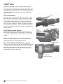
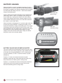
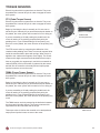
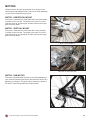
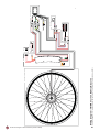
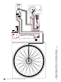
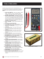
SERVICE MANUAL
(Version 2008a)
Notices. . . . . . . . . . . . . . . . . . . . . . . . . . . . . . . . . . . 2
•
•
•
Fully Charge Batteries before first use . . . . . . . . . . . . . .2
Factors to Maximize Range . . . . . . . . . . . . . . . . . . . . . .2
Wet Weather . . . . . . . . . . . . . . . . . . . . . . . . . . . . . . . . .2
Electronic Component Identification Diagrams . . 3-8
•
•
•
•
•
RMB Series (2008-) . . . . . . . . . . . . . . . . . . . . . . . . . . . .3
RMB Series (2007) . . . . . . . . . . . . . . . . . . . . . . . . . . . . .4
EZGO . . . . . . . . . . . . . . . . . . . . . . . . . . . . . . . . . . . . . . .5
Enlightened w/ TMM4 Sensor. . . . . . . . . . . . . . . . . . . . .6
Enlightened w/ PTS Sensor . . . . . . . . . . . . . . . . . . . . . .7
Electronic Components . . . . . . . . . . . . . . . . . . . . . 7-22
•
•
•
•
•
•
•
•
•
•
•
•
•
Controllers . . . . . . . . . . . . . . . . . . . . . . . . . . . . . . . . . . .8
Brake Inhibitors . . . . . . . . . . . . . . . . . . . . . . . . . . . . . . .8
Throttles . . . . . . . . . . . . . . . . . . . . . . . . . . . . . . . . . . . . .9
Battery Gauges . . . . . . . . . . . . . . . . . . . . . . . . . . . . . . .10
Torque Sensors . . . . . . . . . . . . . . . . . . . . . . . . . . . . . . .11
Motors . . . . . . . . . . . . . . . . . . . . . . . . . . . . . . . . . . . . . .12
Batteries . . . . . . . . . . . . . . . . . . . . . . . . . . . . . . . . . . . . .13
How to Check Battery Voltage via Charger Port . . . . . . .14
Taking Care of your Batteries . . . . . . . . . . . . . . . . . . . . .15
Battery FAQ’s . . . . . . . . . . . . . . . . . . . . . . . . . . . . . . . . .16
Chargers . . . . . . . . . . . . . . . . . . . . . . . . . . . . . . . . . . . .17-19
Main Power Switches . . . . . . . . . . . . . . . . . . . . . . . . . . .20-21
Fuses . . . . . . . . . . . . . . . . . . . . . . . . . . . . . . . . . . . . . . .22
Wiring Diagrams . . . . . . . . . . . . . . . . . . . . . . . . . . . 23
•
•
•
•
•
•
RMB Series (2008-) . . . . . . . . . . . . . . . . . . . . . . . . . . . .23
RMB Series (2007) . . . . . . . . . . . . . . . . . . . . . . . . . . . . .24
EZGO . . . . . . . . . . . . . . . . . . . . . . . . . . . . . . . . . . . . . . .25
Enlightened w/ TMM4 Sensor & Li-Ion Batteries . . . . . .26
Enlightened w/ PTS Sensor & Li-Ion Batteries . . . . . . . .27
Enlightened w/ PTS Sensor & NiMH Batteries . . . . . . . .28
Service Checklist . . . . . . . . . . . . . . . . . . . . . . . . . . 29
Tools Required . . . . . . . . . . . . . . . . . . . . . . . . . . . . 30
Trouble Shooter . . . . . . . . . . . . . . . . . . . . . . . . . . . 31-32
Currie Technologies // Service Manual (Version 2008a)
1
FULLY CHARGE BATTERIES BEFORE FIRST USE - Batteries should be fully
!
charged immediately when they are received and immediately after each use for the
recommended charge times (see below).
• Li-Ion (Lithium Ion) batteries 4-6 hours
• NiMH (Nickel Metal Hydride) 4-6 hours
• SLA (Sealed Lead Acid) batteries 6-8 hours
With proper care and maintenance your Currie Technologies® Hybrid Electric Bicycle will provide ease of use and
be fun to ride. Below are points that will help you to maximize the enjoyment you get from your new hybrid electric
bicycle.
FACTORS TO MAXIMIZE THE RANGE OF YOUR HYBRID ELECTRIC BICYCLE
•
RIDER INPUT - the more the rider pedals the further the distance traveled. Continuous riding, as opposed to
frequent stopping and starting, will yield the greatest range possible
•
ELEVATION GAIN - the flatter the road the further the distance traveled
•
WEATHER - cold weather can adversely affect the battery capacity
•
WIND - traveling with a tailwind will increase distance traveled, traveling into a headwind will decrease
distance traveled
•
TERRAIN - the smoother the terrain (roadways vs. fireroads, etc.) the further the distance traveled
•
RIDER WEIGHT - the lighter the rider, resulting in less drain on the batteries, the further distance traveled
•
BICYCLE MAINTENANCE - a properly maintained bicycle will yield the greatest range possible
•
TIRE PRESSURE - properly inflated tires have less rolling resistance and will be easier to pedal
•
BATTERIES - properly charged and maintained batteries will yield the greatest range possible. Batteries
stored in cold areas (below 50 degrees Fahrenheit / 10 degrees Celsius) will show reduced range. Never
allow batteries to freeze (below 32º Fahrenheit) as this will result in permanent damage to them. Batteries
that have not been kept in optimum condition will show reduced range and run time.
WET WEATHER
!
IT IS RECOMMENDED TO NOT RIDE IN WET WEATHER This hybrid electric bicycle is not meant for use in the
water (damp roads, puddles, rain, streams, etc.). Never immerse this product in water as the electrical system
may be damaged.
Currie Technologies // Service Manual (Version 2008a)
2
Currie Technologies // Service Manual (Version 2008a)
3
Switch (2 position)
Charger Port
Fuse
PAS Sensor Ring
Mounted on left side BB Spindle between left side
crankarm and BB
PAS Sensor
Brake Lever w/
Brake Inhibitor
Mounted on BB Cup between lockring and BB Shell
1 each side of rack
Throttle
(Diagram is for representational purpose only. Your bicycle's electronic components may differ)
ELECTRONIC COMPONENT IDENTIFICATION DIAGRAM - RMB (2008-)
1 each side of rack
Battery Terminal
Mounted on left side of
bicycle
Electric Motor
Optional 2nd battery pack can be
mounted on opposite side
Battery Pack, RMB
Located under the flip-up
handle
Battery Terminal Wire Harness
White Box
Housed inside rack
Black Box
Housed inside rack
Located behind rear reflector
Located on
backside of
battery pack
Controller
Housed inside rack
Currie Technologies // Service Manual (Version 2008a)
4
Charger Port
PAS Sensor
Black Box
White Box
Housed behind seat tube,
accessible on left side
(Diagram is for representational purpose only. Your bicycle's electronic components may differ)
ELECTRONIC COMPONENT IDENTIFICATION DIAGRAM - RMB (2007)
Mounted on left side BB Spindle between left side
crankarm and BB
PAS Sensor Ring
, accessible on left side
Located behind seat tube
Switch (2 position)
Housed behind seat tube,
accessible on left side
Mounted on BB Cup between lockring and BB Shell
1 each side of chainstay
Battery Terminal Wire Harness
Mounted on left side of
bicycle
Electric Motor
1 each side of rack
Battery Terminal
Located on
backside of
battery pack
Fuse
Shown w/ optional 2nd
battery pack
Battery Pack, RMB
Located under the flip-up
handle
Controller
Housed behind seat tube,
accessible on left side
Brake Lever w/
Brake Inhibitor
Throttle
Currie Technologies // Service Manual (Version 2008a)
5
Controller
Housed behind seat tube, accessible on left side
Located inside
of battery pack
Fuse
Battery Terminal
Wire Harness
(Diagram is for representational purpose only. Your bicycle's electronic components may differ)
ELECTRONIC COMPONENT IDENTIFICATION DIAGRAM - EZGO
Electric Hub Motor
Charger Port
Battery Pack, STB
Switch
Located on left side
of battery pack
Throttle
Brake Lever w/ Brake Inhibitor
Currie Technologies // Service Manual (Version 2008a)
6
Controller
Battery Pack
Housed inside of downtube,
accessible via the downtube cap
Charger Port
Battery Gauge w/ Power Adjuster
(Diagram is for representational purpose only. Your bicycle's electronic components may differ)
ELECTRONIC COMPONENT IDENTIFICATION DIAGRAM - ENLIGHTENED W/ TMM4 SENSOR
Located under
downtube cap
Fuses
Housed under chainstays
and behind BB Shell
TMM4 Sensor
Electric Hub Motor
Switch
Located on left side
of battery pack
Currie Technologies // Service Manual (Version 2008a)
7
Battery Pack
Housed inside of downtube,
accessible via the downtube cap
Located under
downtube cap
Fuse
Charger Port
Battery Gauge w/ Power Adjuster
(Diagram is for representational purpose only. Your bicycle's electronic components may differ)
ELECTRONIC COMPONENT IDENTIFICATION DIAGRAM - ENLIGHTENED W/ PTS SENSOR
Located on backside
of crankset
PTS Sensor
Housed under chainstays
and behind BB Shell
Controller
Electric Hub Motor
Switch
Located on left side
of battery pack
ELECTRONIC COMPONENTS
CONTROLLERS
The controller is the “brain” of the system; it takes the input
signals from sensor/throttle and converts it into pulses that the
motor can use. The controller is also “smart”. If it senses there
is no input coming in after five minutes, it turns the bike
off to conserve battery power. Therefore if the power switch
is in the “on” position and the lights on the battery gauge are
off and there is no power to the hub motor, the controller most
likely went into stasis mode. To reset, cycle the switch “OFF”
and “ON”.
Example of controller
used in EZGO Series
Example of controller used
in Enlightened Series
If the battery pack voltage is low (<21v) the controller will
automatically turn off to prevent irreparable damage to
the battery pack. At or near this point, the motor may start
shuddering (vibrating or making a strange shaking noise).
Recharge battery before using again.
Example of controller
used in RMB Series
BRAKE INHIBITORS
A microswitch housed inside of the brake lever body activates
when the brake lever in pulled thus cutting power to the motor.
Depending on your model of hybrid electric bicycle you may
have one or two brake inhibitors.
If the brake inhibitor needs replacing the entire brake lever
assembly will need to be replaced as the microswitch is not
removable from the brake lever body.
Brake Lever with Brake Inhibitor
Location of microswitch housed
inside of the brake lever body
Currie Technologies // Service Manual (Version 2008a)
8
THROTTLES
Throttles are equipped on some models of electric bicycles.
Throttles operate by rotating the throttle towards the rider much
like a motorcycle. They generally are the inner half of the right
side handlebar grip and may also contain a battery gauge. The
more you twist the throttle, the faster the motor system will
propel the bicycle.
TAG (Twist and Go)
Before you begin riding, turn the main power switch on, then
start riding as you would ride any regular, non motor assisted
bicycle. After you have begun to ride, slowly twist the throttle
(on equipped models) towards you. The more you twist the
throttle, the more motor power will be applied to the wheels.
You may feel the pedals get a “lighter” feel than riding without
the motor assisting you. Once you have twisted the throttle all
the way, the motor will accelerate you to its full speed of about
15mph (24 km/h).
TAG Throttle
PAS (Pedal Activated System)
Electric bicycles with this system have a throttle that is only
active when the pedals are in a forward motion. A sensor ring
on the bottom bracket spindle rotates and a sensor reads this
rotation.
Begin by first riding as if you are on a normal non-electric
bicycle, then while the pedals are in motion slowly twist the
throttle towards you to activate the motor power.
PAS / TAG THROTTLE SWITCH (if equipped)
PAS Sensor and
PAS Sensor Ring
The type of system enables the rider to select between the PAS
and TAG modes via the red thumb button. Refer to the TAG
and PAS sections to find out how these modes work. Note:
When using the TAG mode you will use more battery power
and thus shorten range of the bicycle.
PAS / TAG
Selector Switch
Currie Technologies // Service Manual (Version 2008a)
9
BATTERY GAUGES
When the throttle or sensor is engaged (powering the motor)
and the bicycle is in motion, the LED’s on the battery gauge (on
the throttle or separate unit) indicate instantaneous line voltage
as measured at the battery terminals -- and not the available
energy in the battery pack.
The line voltage will fluctuate depending on the instantaneous
load that the motor is under. For example, when starting out
from a dead stop, or going up a steep hill, the motor will be
under a high load and may show a reduced number of LED's
(some throttles depending on the color of the LED’s will show
the “Yellow” or even “Red” LED).
When the throttle is disengaged (i.e. no power to the motor due
to the bicycle being stationary or coasting) the LED’s on the
throttle will indicate the voltage of the battery pack. The voltage
of the battery pack will rise when no load is on the motor. The
best indication of how much battery life is remaining is to check
the throttle LED’s, after reaching cruising speed, on a flat
straight road as this will allow the battery voltage to stabilize
and give a much more accurate reading.
TAG Throttle with
Battery Gauge
PAS / TAG
with Battery Gauge
BATTERY GAUGE WITH POWER ADJUSTER
This unit is featured on the Enlightened series of bicycles. Not
only does it act like a battery gauge but it also enables the rider
to vary the level of power assistance (1 LED = least amount
of power assistance, 5 LED's = maximum amount of power
assistance).
Press the "+" button to increase the amount of power
assistance (Note that this will also decrease the range of the
bicycle because more battery power is being used).
Press the "-" to decrease the amount of the power assistance
(Note that this will also increase the range of the bicycle
because less battery power is being used).
Currie Technologies // Service Manual (Version 2008a)
10
TORQUE SENSORS
Electric bicycles with this system have no throttle. They must
be pedaled like a normal bicycle in order to engage the motor
drive system.
PTS (Pedal Torque Sensor)
Electric bicycles with this system have no throttle. They must
be pedaled like a normal bicycle in order to engage the motor
drive system.
Begin by first riding the bicycle normally as if it were not an
electric bicycle. Naturally as you accelerate and push harder on
the pedals, the motor system will increase its force to help you.
If you are ascending a hill and pushing the pedals hard, the
motor will assist you by pushing proportionately with your
pedaling force. If you are descending a hill and putting very
little force on the pedals, the motor will also not be pushing very
much.
Crankset with
PTS Torque Sensor
The PTS sensor works by measuring the deflection of the
crankset under pedaling load. There are several magnets inline
inside the crankset held in place with springs. When torque is
applied to the crankset the magnets move slightly. The sensor
measures this slight movement and calculates that as torque.
Also as you pedal, the magnets spin, and this is measured as
cadence (RPM). All this information is gathered by the sensor
and fed into the controller to be analyzed and output power
impulse bursts are sent to the motor.
TMM4 (Frame Torque Sensor)
Electric bicycles with this system have no throttle. They must
be pedaled like a normal bicycle in order to engage the motor
drive system.
Begin by first riding the bicycle normally as if it were not an
electric bicycle. Naturally as you accelerate and push harder on
the pedals, the motor system will increase its force to help you.
If you are ascending a hill and pushing the pedals hard, the
motor will assist you by pushing proportionately with your
pedaling force. If you are descending a hill and putting very
little force on the pedals, the motor will also not be pushing very
much.
The TMM4 sensor works by measuring the deflection between
the frame and right side dropout. The sensor measures this
slight deflection and calculates that as torque.
This torque value is fed into the controller to be analyzed and
output power impulse bursts are sent to the motor.
Currie Technologies // Service Manual (Version 2008a)
TMM4 Sensor
11
MOTORS
All hybrid electric bicycles are powered via an electric motor.
Various types and wattage levels of motors are used depending
on your model of hybrid electric bicycle.
MOTOR - HORIZONTAL MOUNT
The motor is mounted on a motor plate and is hung horizontally
in relation to the rear axle. The output of the motor is run thru
reduction gears to an output gear. A chain connects the output
gear to the rear wheel.
MOTOR - VERTICAL MOUNT
The motor is mounted on a motor plate and is hung vertically
in relation to the rear axle. The output of the motor is run thru
reduction gears to an output gear. A chain connects the output
gear to the rear wheel.
Motor - Horizontal Mount
Detail view of motor drive chain
MOTOR - HUB MOTOR
The motor is housed inside the front or rear hub (depending on
your model of hybrid electric bicycle) and drives the wheel via a
planetary gear system. This gear system reduces the speed of
the electric motor and provides the torque needed.
Currie Technologies // Service Manual (Version 2008a)
12
BATTERIES
Currie Technologies® utilizes several types of batteries housed
in a variety of battery cases depending on the platform of hybrid
electric bicycle.
Enlightened - This series of hybrid electric bicycle will use
either NiMH (Nickel Metal Hydride) or Li-Ion (Lithium Ion) 24v
battery pack.
Example of NiMH Battery Pack as
used in the Enlightened Series
The battery pack is housed inside the down tube which is
accessible via a cap on the bottom of the down tube.
RMB (Rack Mounted Batteries) - This series of hybrid electric
bicycle will use SLA (Sealed Lead Acid) 24v battery packs.
Battery packs (dual) are mounted on both sides of the rear
rack. These battery packs are secured with a lock to prevent
unwanted removal while the bicycle is parked.
STB (Seat Tube Batteries) - This series of hybrid electric
bicycle will use SLA (Sealed Lead Acid) 24v or 36v battery
pack.
The battery pack is mounted behind the seat tube. This type
of battery pack may be secured with a lock or a spring loaded
retention pin depending on the platform of hybrid electric
bicycle.
Example of STB Battery Pack
Example of RMB Battery Pack
BATTERY TERMINAL COVERS
Bicycles with Rack Mount Batteries have dual power switches
and are equipped with battery terminal cover(s) (see photo).
These protect the battery terminals from debris and water when
the terminal is not in use (i.e. when the battery(s) is removed
from the bike).
These battery terminal covers need to be removed in order for
the battery to make contact with terminals.
Currie Technologies // Service Manual (Version 2008a)
13
HOW TO CHECK BATTERY VOLTAGE VIA THE
CHARGER (XLR) PORT
Using a multimeter set to vDC (see instructions provided by
multimeter manufacturer) insert the Red (positive) probe into
hole #1 and the Black (negative) probe into hole #2.
If you get a negative value (i.e. -26.2v) you simply have the
probes reversed.
For a 24v battery pack (regardless of the type of battery) a
reading of above 26v indicates that the batteries are full.
HOW TO CHECK BATTERY VOLTAGE VIA THE
CHARGER (2V1H OR 3V) PORT
2v1h Charger Port
Using a multimeter set to vDC (see instructions provided by
multimeter manufacturer) carefully touch the Red (positive)
probe to the #1 pin and the Black (negative) probe to the #2
pin.
If you get a negative value (i.e. -26.2v) you simply have the
probes reversed.
For a 24v battery pack (regardless of the type of battery) a
reading of above 26v indicates that the batteries are full.
Pin # 1
Pin # 2
For a 36v battery pack (regardless of the type of battery) a
reading of above 38v indicates that the batteries are full.
3v Charger Port
Currie Technologies // Service Manual (Version 2008a)
14
TAKING CARE OF YOUR BATTERIES
Proper maintenance of the batteries will maximize their lifespan and available ride time. Currie Technologies® warrants
your new batteries from the date of purchase but only if properly cared for. Refer to the limited warranty for details.
Currie uses SLA (Sealed Lead Acid), NiMH (Nickel Metal Hydride) or Li-Ion (Lithium Ion) batteries in all of our hybrid
electric bicycles. These are all very user friendly types of batteries when cared for properly.
•
Batteries should be fully charged immediately when they are received for the recommended charge times.
FULLY CHARGE BATTERIES BEFORE FIRST USE. Below are the recommended charge times for each type
of batteries.
• Li-Ion (Lithium Ion) batteries 4-6 hours
• NiMH (Nickel Metal Hydride) 4-6 hours
• SLA (Sealed Lead Acid) batteries 6-8 hours
•
Charge batteries at least every 90 days for NiMH & Li-Ion and every 30 days for SLA until normal use is
resumed.
•
Always store bicycle with fully charged batteries.
•
Never charge the batteries for more than 24 hours.
•
Always disconnect the charger from the wall outlet and bicycle when charging is complete (as indicated by the
status on the charger) before storing the bicycle.
•
DO NOT STORE BATTERIES BELOW 50º FAHRENHEIT AND NEVER ALLOW BATTERIES TO FREEZE
(BELOW 32º FAHRENHEIT).
•
Bikes are equipped with a 5 minute sleep mode. If no activity is detected after 5 minutes the bike will go into
stasis mode to conserve the batteries. To restart, cycle the power switch “OFF” then “ON”. Bikes are not to be
stored in the 5 minute sleep mode. Be sure to turn the power switch "OFF" when the bike in not in use.
•
ALWAYS BE SURE TO TURN THE BIKE “OFF” AFTER EACH USE VIA THE ON/OFF POWER SWITCH. If
you have left the power switch on or your product has not been charged for a long period of time, the batteries
may reach a stage at which it will no longer hold a charge.
•
Be friendly to the environment! Be sure to recycle your old batteries at a local battery recycling center. Do not
throw them in the garbage!
•
Frequent “stops and starts” will drain a battery more quickly than continuous riding
•
Even with proper care, rechargeable batteries does not last forever. Average battery life depends on use and
conditions.
Disposal requirements for batteries
The batteries supplied in your iZip™ hybrid electric bicycle are unsuitable for regular trash disposal receptacles. Take
the battery to an approved battery recycler.
Concerns regarding battery safety
All iZip™ hybrid electric bicycles batteries. In the unlikely event that you suspect fluid is leaking from your battery
please follow precautions below.
Internal exposure: Contact a physician immediately.
External exposure: Contact a physician immediately. Flush immediately for 15 minutes if acid gets in eyes or on skin.
!
Battery acid can cause blindness or severe burns. Contact physician immediately
if you have been exposed to battery acid.
Currie Technologies // Service Manual (Version 2008a)
15
BATTERY FAQ'S
Q: Do I need to charge the batteries before using them?
A: Yes, you should charge the batteries fully before first using them.
Q: What is conditioning (NiMH only)?
A: The conditioning process is performed by first draining the batteries and then charging them fully. Conditioning is recommended
for every ten to twenty charges.
Q: Do I need to "break-in" my batteries?
A: Yes, the batteries used in the Currie Hybrid Electric Bicycles will need to have a “break-in” cycle consisting of ~ three discharge/
charge cycles before they will reach optimum performance. This involves three complete discharges and three complete
recharges. After this initial “break-in” cycle the batteries will have maximum possible performance and less line voltage
fluctuations under load.
Q: How long will the batteries hold their charge?
A: All batteries will self-discharge when not in use. The self-discharging rate depends on the temperature at which they are stored.
Excessively cold or hot storage temperatures will drain the batteries faster than normal. Ideally the batteries should be stored at
room temperature.
Q: Why should I recharge my batteries at least every 90 days (NiMH & Li-Ion) and every 30 days (SLA) when I am not using
them?
A: Batteries naturally loose their charge over time. To keep the batteries in optimal condition and extend their life, it is recommended
that a top-off recharge be performed at least every 90 days for NiMH & Li-Ion batteries and at least every 30 days for SLA
batteries. Not maintaining the batteries will cause them to lose performance and have a shorten lifespan.
Q: What happens if I leave the power switch on longer than 5 minutes?
A: Currie bikes are equipped with a 5 minute shut-off mode. If no activity is detected after 5 minutes the bike will turn itself off to
protect the batteries. To restart, cycle the power switch (OFF then ON). If you have left the power switch on or your product has
not been charged for a long period of time, the batteries may reach a stage at which it will no longer hold a charge.
Q: Will I get more performance from my bike if I leave the batteries to charge longer?
A: No, once the batteries are fully charged (as indicated by the light on the charger) it is best to unplug them from the charger.
Leaving the batteries charging longer than necessary is called “overcharging” and will not increase performance. Currie-supplied
chargers are designed to avoid over-charging a battery. Still we recommend that you always unplug a charger after the unit is
fully charged to avoid the possibility of unanticipated circumstances such as an unexpected power surge from a lightning strike
(or other power line anomaly) potentially causing damage. Only use Currie-supplied chargers.
Q: Is it normal that the batteries get warm when recharging?
A: Yes, it is normal that the batteries will become warm to the touch during the recharging process. This is because the increase of
internal resistance and less energy conversion efficiency from electric energy to chemical energy.
Q: How long will my batteries last before needing replacement?
A: Average battery life depends on use and conditions. Even with proper care, rechargeable batteries does not last forever.
Q: How will I know when to replace my batteries?
A: Some or all of the following may occur possibly indicating that the batteries have reached their useful lifespan and will need to be
replaced.
Shorter ride time than normal
•
Less power while riding than when your hybrid electric bicycle was new
•
Reduced time to full charge as indicated by indicator light on charger. For example a fully depleted SLA battery should take
•
8-10 hours to fully charge, if the charger shows a full charge after only 2 hours than the batteries may need to be replaced.)
Inability to get a full charge from the charger. Charger never stops blinking or stays red even after charging for the full time
•
Q: What is battery sulfation and how do I prevent it?
A: During normal operation of lead-acid batteries, lead sulfate forms on the battery plates. This process is called sulfation. During
this process the sulfates expand and crystallize, choking the plates and thus reducing battery efficiency to the point where the
battery will not accept a charge. Sulfation build-up on battery plates is a common cause of battery failure. The easiest way to
prolong the onset of sulfation is to keep the batteries fully charged.
Q: What should I do with my old batteries?
A: Contact your local battery recycling center in order to properly dispose of the batteries. Never dispose of batteries in the garbage.
Currie Technologies // Service Manual (Version 2008a)
16
CHARGER
The hybrid electric bicycle comes with its own "Smart Charger” that connects with an easy-access charger port for
recharging the batteries. This charger unit has lights that show the battery charge status. Refer to the instructions that
appear on the charger unit and its instructions.
Batteries work best when they have a full charge, so always be sure to recharge them fully after each ride. If you leave
them in a run-down condition, without recharging them, it will shorten their life expectancy.
•
•
•
Li-Ion (Lithium Ion) batteries - charge for 4-6 hours for full charge
NiMH (Nickel Metal Hydride) batteries - charge for 4-6 hours for full charge
SLA (Sealed Lead Acid) batteries - charge for 6-8 hours for full charge
The charger may get warm to the touch, so make sure you charge them in an open area and do not lay anything on
the charger unit while charging. Although you cannot over-charge the batteries using the Currie “Smart Charger”, we
recommend that you do not leave the charger plugged in for more than 24 hours.
If your charger shows a solid green light after charging for a short period of time, your battery may have been only
partially discharged (short ride), or this may be the sign of a partially worn out battery with reduced storage capacity.
Continue charging for the full time, to cover all the bases. If the battery still has not charged, you may need to replace
it.
Even with proper care, a rechargeable battery does not last forever. Average battery life depends on use and
conditions.
!
The charger and charger port should be regularly inspected for damage (cord, plug, enclosure, etc.).
If damage is found stop using until the damaged part can be repaired or replaced.
Currie Technologies // Service Manual (Version 2008a)
17
HOW TO USE THE NIMH AND LI-ION CHARGERS
Before using the charger locate the voltage selector switch
(NiMH and Li-Ion chargers only) on the back of the charger.
Select either 115 Volts or 230V Volts depending on the country
you reside in. Using the 115V setting in a 230V country will
permanently damage the batteries and/or set off the fuse.
Using the 230V setting in a 115V country will put no useful
charge on the batteries.
Back Side of Charger
Example of NiMH Charger
115
1. Plug the charger into the outlet and turn the charger
“ON” via the switch on the back side. The red power
light on the front of the charger will illuminate when the
charger is working properly.
2. Insert the XLR plug (round plug with 3 pins) into the
charger port on the bike being sure the charger plug
is fully seated in the charger port. The second light
will start to flash orange for several seconds while the
charger is “seeking” the battery.
3. Once the charger has "found" the battery the blinking
orange light will stop flashing and turn solid orange
and the cooling fan will start. At this point the charge
process has begun.
4. Once the battery reaches full charge, the orange light
will turn solid green.
5. When charging is complete, unplug the charger from
the wall before removing it from the charger port.
Example of Li-Ion Charger
Charge for the full time. If the battery still has not charged, you
may need to replace it.
Orange/Green light
Electric Bikes with internal battery packs - Rotate the charger port cover and attach charger.
FUSE
Front Side of Charger
!
Use only Currie Authorized Li-Ion chargers with bicycles
equipped with Li-Ion batteries. Using any other charger
will damage the batteries and void your warranty.
!
Use only Currie Authorized NiMH chargers with bicycles
equipped with NiMH batteries. Using any other charger
will damage the batteries and void your warranty.
Currie Technologies // Service Manual (Version 2008a)
18
HOW TO USE THE SLA CHARGERS (STANDARD)
1. Plug the charger into the outlet. The indicator light on
the top of the charger will illuminate when the charger
is working properly. Refer to the sticker on the charger
for actual status light indication.
2. Insert the plug (XLR, 2v1h or 3v) into the charger port
on the bike being sure the charger plug is fully seated
in the charger port. The light should be solid red or
blinking green to indicate charging however you will
need to refer to the sticker on the charger for actual
status light indication.
3. Once the battery reaches full charge, the light will
return to solid green however you will need to refer
to the sticker on the charger for actual status light
indication.
4. When charging is complete, unplug the charger from
the wall before removing it from the charger port.
Charge for the full time. If the battery still has not charged, you
may need to replace it.
Example of SLA Charger
w/ XLR Plug
SLA Charger could come with the below plugs
depending on your model of hybrid electric bicycle
XLR Plug
Electric Bikes with Seat Tube Mounted Battery (STB) Packs
- Remove the power cable from the charger port and attach
charger.
2v1h Plug
3v Plug
Electric Bikes with Rack Mounted Battery (RMB) Packs Lift the battery pack handle to expose the charger port and
attach charger.
!
Use only Currie Authorized SLA chargers with bicycles
equipped with SLA batteries. Using any other charger
will damage the batteries and void your warranty.
Currie Technologies // Service Manual (Version 2008a)
19
MAIN POWER SWITCHES
Always turn the power switch (all types) “OFF” when
charging the hybrid electric bicycle. This prevents
accidental/unintentional activation of the motor and
avoids the possibility of unanticipated circumstances
such as an unexpected power surge from a lightning
strike (or other power line anomaly) potentially causing
damage to the electrical components.
!
STANDARD POWER SWITCHES
The power switch may be located, depending on the model of
bike, in the following locations
•
•
On the battery pack itself (CX and STB Series)
On the side of the downtube (Enlightened Series)
Enlightened Bicycles
Be sure to turn the switch off whenever you are not using the
bicycle or when charging the bicycle.
CX Bicycles
STB Bicycles
DUAL POWER SWITCHES
Bikes with dual rack mounted battery packs (RMB 2007 and
RMB 2008) are also equipped with a dual power switch. This
switch has two "ON" positions that corresponds to the two
battery packs. The switch is "OFF" when placed at the center
position.
The power switch may be located, depending on the model of
bike, in the following locations
•
•
On the side of the controller box (RMB Series 2007)
On the backside of the rack behind the rear reflector
(RMB Series 2008-)
•
Be sure to turn the switch off whenever you are not using the
bicycle or when charging the bicycle.
RMB Bicycles (2007)
Meaning of Dual Power
Switch markings
-
Pack 1 “ON”
O “OFF”
= Pack 2 “ON”
RMB Bicycles (2008-)
Currie Technologies // Service Manual (Version 2008a)
20
KEY LOCK POWER SWITCHES
Certain bicycles (ex. HG1000) are equipped with a key lock
power switch. This feature provides added security allowing
only the person with the key to turn the power on or off. This
key lock switch has the same function as a standard power
switch.
Be sure to turn the switch off whenever you are not using the
bicycle or when charging the bicycle.
Key Lock Power Switch
Currie Technologies // Service Manual (Version 2008a)
21
FUSES
All Currie Technologies® Hybrid Electric Bicycles are equipped
with fuses. The fuse may be located, depending on the model
of bike, in the following locations
•
•
•
•
•
•
CX Series (40a glass type fuse) - On the battery pack,
externally accessible
RMB Series (40a glass type fuse) - On the backside of
the battery pack, externally accessible
STB Series (24v, 40a glass type fuse) - Inside the
battery, must open the battery pack to access
STB Series (36v, 40a glass type fuse) - On the battery
pack, externally accessible
Enlightened Series (NiMH, 30a blade type fuse)
- inside the bottom end of the downtube, remove
downtube cap to access
Enlightened Series (Li-Ion, 30a blade type fuse &
5a blade type fuse) - inside the bottom end of the
downtube, remove downtube cap to access
CX Bicycles
RMB Bicycles (2007, 2008)
STB Bicycles (36v)
STB Bicycles (24v)
In the event of an overload the fuse will pop (see graphic below
for example) and need to be replaced. In this instance replace
only with approved part from Currie Technologies®
!
Risk of fire. Do not bypass fuse.
Enlightened Series (NiMH)
Blade Type Fuse
GOOD
Blade Type Fuse
BAD
Notice broken filament
Glass Type Fuse
GOOD
Glass Type Fuse
BAD
Notice broken filament
Currie Technologies // Service Manual (Version 2008a)
Enlightened Series (Li-Ion)
22
Currie Technologies // Service Manual (Version 2008a)
BRAKE LEVER, LEFT
(Diagram is for representational purpose only. Your bicycle's wiring system may differ)
WIRE HARNESS, BATTERY PORT
SWITCH
BATTERY PORT
Secondardy Battery Box
(optional)
WIRE HARNESS, SWITCH
WIRE HARNESS, BATTERY PORT
Wiring Diagram - TAG/PAS w/ RMB Bicycles (2008-)
MOTOR
CONTROLLER
1:1 ASSIST SENSOR
(a.k.a. “BLACK BOX”)
ASSIST CONVERTER
(a.k.a. “WHITE BOX”)
FUSE
BATTERY PORT
BATTERY
WIRE HARNESS, BATTERY CASE
CHARGER PORT
BATTERY
3
BATTERY CASE (Complete)
1
2
THROTTLE
WIRING DIAGRAMS
23
Currie Technologies // Service Manual (Version 2008a)
24
BRAKE INHIBITOR
(Front Brake Lever)
(Diagram is for representational purpose only. Your bicycle's wiring system may differ)
Wiring Diagram - TAG/PAS w/ RMB Bicycles (2007)
MOTOR
S/N 245061215135
S/N 070104525
Make Date 2007-01-17
CONTROLLER
24v / 35a
FUSE
40a
Glass Type
BATTERY
12V / 10Ah
BATTERY
12V / 10Ah
ENCLOSED BATTERY BOX
(Box 1 is standard with bike)
(The fuse is accessible externally)
THROTTLE
2
3
1
Currie Technologies // Service Manual (Version 2008a)
25
BRAKE LEVER, LEFT
WHEEL, REAR W/ HUB MOTOR
CONNECTOR IN USE
(Diagram is for representational purpose only. Your bicycle's wiring system may differ)
Wiring Diagram - EZGO (TAG system) w/ STB Bicycles
CONTROLLER
BRAKE LEVER, RIGHT
FULL
LOW
HALF
L
E
N
THROTTLE
BATTERY
BATTERY
FUSE
OFF
ON
SWITCH
BATTERY CASE (Complete)
EZGO (STB w/ SLA Batteries) Bikes (2008 USA) WIRING DIAGRAM
WIRE HARNESS, BATTERY PORT
WIRE HARNESS,ADAPTER (DM-E-250C)
Currie Technologies // Service Manual (Version 2008a)
26
(Tentative diagram is for representational purpose only. Your bicycle's wiring system may differ)
Wiring Diagram - TMM4 w/ Li-Ion Battery Bicycles
WHEEL, REAR w/ HUB MOTOR
5
30
BATTERY
CHARGER PORT
OFF
ON
SWITCH
2
3
1
BATTERY GAUGE
POWER ADJUST
BATTERY GAUGE w/ TORQUE ADJUSTER
TMM4 (Tentative 2008) WIRING DIAGRAM
TMM4 SENSOR
?
? TBD
TBD
CONTROLLER
Currie Technologies // Service Manual (Version 2008a)
27
(Diagram is for representational purpose only. Your bicycle's wiring system may differ)
Wiring Diagram - PTS w/ Li-Ion Battery Bicycles
WHEEL, REAR w/ HUB MOTOR
5
30
BATTERY
CHARGER PORT
OFF
ON
SWITCH
2
3
1
BATTERY GAUGE
POWER ADJUST
BATTERY GAUGE w/ TORQUE ADJUSTER
iZip Trekking Li (2007) WIRING DIAGRAM
Rear View of Crankset
(PTS Sensor is removeable and
available seperate from crankset)
CRANKSET w/ PTS SENSOR
CONTROLLER
Currie Technologies // Service Manual (Version 2008a)
28
BATTERY
NiMH
24v / 9a
OFF
ON
(Diagram is for representational purpose only. Your bicycle's wiring system may differ)
Wiring Diagram - PTS w/ NiMH Battery Bicycles
HUB MOTOR
FUSE
30a
Blade Type
Controller
2
3
1
Connector
not used
4th pin
not used
Rear View of Crankset
(PTS Sensor is removeable from crankset)
SERVICE CHECKLIST
FREQUENCY
TASK
Before every ride
Be sure batteries are fully charged
Check tire pressure
Check brake operation
Check wheels for loose spokes
Perform safety check
After every ride
Be sure to fully charge batteries
Quick wipe down with damp cloth
Weekly
Lubrication as per schedule 1
Monthly
Inspect electrical wires
Inspect electrical connectors
Inspect all electronic components
Lubrication as per schedule 1
Check derailleur adjustment
Check brake adjustment
Check brake and gear cable adjustment
Check tire wear and pressure
Check wheels are true and spokes tight
Check hub, head set and crank bearings for looseness
Check pedals are tight
Check handlebars and stem are tight
Check seat and seat post are tight and comfortably adjusted
Check frame and fork for trueness
Perform safety check
Every Six Months
Lubrication as per schedule 1
Check all points as per monthly service
Check and replace brake pads, if required
Check chain for excess play or wear
Yearly
Lubrication as per schedule 1
Currie Technologies // Service Manual (Version 2008a)
29
TOOLS REQUIRED
In order to carry out basic service and maintenance on an
iZip™ Hybrid Electric Bicycle we recommend the following tools
in addition to the standard assortment of bicycle shop
tools.
1. DIGITAL MULTIMETER - used to test voltage, current
(amps), continuity of electric components. Digital
multimeter offer better accuracy than analog versions.
2. BATTERY LOAD TESTER - This device puts a “load”
on the 12v battery so that the actual battery condition
of the load can be measured. Unit measured individual
12v cells only. The RMB and STB battery packs would
need to be opened in order to test the individual 12v
cells inside. This device is not intended to work with
the NiMH or Li-Ion battery packs.
3. WIRE STRIPPERS - cleanly removes insulation from
wires
4. ELECTRICAL INSULATION TAPE
5. SOLDERING IRON & LEAD FREE SOLDER - used to
repair wires and connectors
6. Hot glue gun - used to seal connecting pin in the
connectors
7. 24V BATTERY PACK - extra battery pack that has
been properly tested and is known to be in good
condition
8. 36V BATTERY PACK - extra battery pack that has
been properly tested and is known to be in good
condition
9. PAS/TAG THROTTLE - extra unit that has been
properly tested and is known to be in good condition
10. TAG THROTTLE - extra unit that has been properly
tested and is known to be in good condition
11. CONTROLLER FOR RMB SERIES - extra unit that
has been properly tested and is known to be in good
condition
12. CONTROLLER FOR EZGO SERIES - extra unit that
has been properly tested and is known to be in good
condition
13. CONTROLLER FOR ENLIGHTENED (W/ PTS
SENSOR) SERIES - extra unit that has been properly
tested and is known to be in good condition
14. PTS SENSOR - extra unit that has been properly
tested and is known to be in good condition
15. CONTROLLER FOR ENLIGHTENED (W/ TMM4
SENSOR) SERIES - extra unit that has been properly
tested and is known to be in good condition
16. TMM4 SENSOR - extra unit that has been properly
tested and is known to be in good condition
17. BRAKE LEVER W/ BRAKE INHIBITOR - extra unit that
has been properly tested and is known to be in good
condition
Currie Technologies // Service Manual (Version 2008a)
Example of Digital Multimeter
Example of Battery Load Tester
30
TROUBLE SHOOTER
PROBLEM
POSSIBLE CAUSE
REMEDY
Bicycle has reduced range and/or
speed
Low batteries
Charge batteries for recommended time
Faulty batteries
Replace batteries
Low tire pressure
Inflate tires to recommended pressure
Brakes dragging against rim
Adjust brakes and/or true wheel
Riding in hilly terrain, headwind, etc.
Reduced range to be expected in these
types of terrain and/or weather conditions
Hub motor (Enlightened Series)
makes a "clicking" noise and has
reduce power and/or shuts off
Low batteries
Charge batteries for recommended time
Damaged planetary gears
Replace hub motor/wheel
No power when the switch is
turned "ON"
Blown fuse
Replace fuse
Loose connectors
Check all connectors
Damaged wires
Inspect all wires for damage
Faulty switch
Replace switch and retest
Faulty controller
Replace controller and retest
Loose connectors
Check throttle and/or battery gauge connectors
Damaged wires
Inspect all wires
Bicycle operates OK but battery
gauge does not light up
Faulty battery gauge
Battery gauge lights up but bicycle Faulty brake inhibitor
does not operate
Loose motor wire connector
Brake inhibitors (on bicycles so
equipped) do not cut power to the
motor when brakes are applied
Bicycle runs at full speed without
pedaling
Replace battery gauge
Replace brake inhibitor(s) and retest
Check motor wire connector
Faulty PTS sensor (Enlightened Series)
Replace PTS sensor and retest
Faulty TMM4 sensor (Enlightened Series)
Replace TTM sensor and retest
Loose connectors
Check brake inhibitor connectors
Damaged wire(s) on brake inhibitors
Inspect brake inhibitor wires
Faulty brake inhibitor
Replace brake inhibitor(s) and retest
Faulty controller
Replace controller and retest
Faulty PTS sensor (Enlightened Series)
Replace PTS sensor and retest
Faulty TTM sensor (Enlightened Series)
Replace TTM sensor and retest
Faulty throttle
Replace throttle and retest
Faulty controller
Replace controller and retest
Bicycle (RMB or STB Series)
Sensor and sensor ring not aligned
works in TAG mode but not in PAS
mode
Faulty "White Box"
Realigned so gap between sensor and
sensor ring is 1-2mm
Battery indicates full charge when
tested at the charger port but
bicycle does not operate
Blown fuse
Replace fuse
Replace "White Box" and retest
Loose connectors
Check all connectors
Poor contact between battery terminals
Inspect and clean battery terminals
Throttle (on bicycles so equipped)
does not spring back to neutral
position
Grip jammed against throttle
Reposition grip so gap between it and the
throttle is 1-2mm
Faulty throttle
Replace throttle
Bicycle has intermittent power
Loose connectors
Check all connectors
Loose fuse
Check fuse connector
Damaged wires
Inspect all wires
Currie Technologies // Service Manual (Version 2008a)
31
PROBLEM
POSSIBLE CAUSE
REMEDY
Charger shows a full charge in an
unusually short amount of time
Faulty charger
Replace charger
Faulty batteries
Replace batteries
Indicator light on charger not illuminated when charger is plugged
into outlet
Outlet has no power
Check outlet for power
Blown fuse (NiMH and Li-Ion chargers)
Replace fuse
Faulty charger
Replace charger
Charger (SLA) indicator light
never changes status indicating it
is charging
Damaged wire from charger port to battery
Inspect charger port wires
Damaged wire(s) on charger XLR plug
Inspect charger wire(s) and connection to
at XLR plug
Faulty charger
Replace charger
Charger (NiMH and Li-Ion) indicator light only flashes orange and
never changes to red
Damage wire from charger port to battery
Inspect charger port wires
Faulty charger
Replace charger
Faulty batteries
Replace batteries
Cooling fan on charger (NiMH
and Li-Ion) does not turn on even
though indicator light changes to
red when connected to batteries
Faulty charger
Replace charger
Currie Technologies // Service Manual (Version 2008a)
32