1
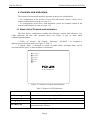
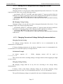
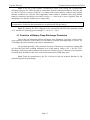
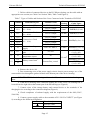
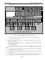
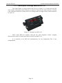
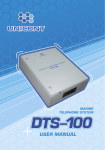
Unicont SPb Ltd Power Supply/Automatic Battery Charger PCH-205 Technical Documentation (205-1-27062012) St. Petersburg 2012 Unicont SPb Ltd Technical Documentation PCH-205 Table of Contents 1. GENERAL DATA ............................................................................................................4 2. DELIVERY SET ...............................................................................................................4 3. SPECIFICATIONS ..........................................................................................................6 4. SAFETY ENGINEERING INSTRUCTIONS ...............................................................7 5. OPERATION PRINCIPLE .............................................................................................8 6. CONTROLS AND INDICATORS ..................................................................................9 7. INSTALLATION AND CONNECTION......................................................................14 8. ALARM SIGNALS OF PCH-205 .................................................................................19 9. TRANSPORTATION AND STORAGE ......................................................................20 10. RECYCLING ..................................................................................................................21 11. WARRANTY ..................................................................................................................22 12. DATE OF PACKING .....................................................................................................23 13. ACCEPTANCE DETAILS ............................................................................................23 14. DATE OF COMMISSIONING .....................................................................................23 Page 2 Unicont SPb Ltd Technical Documentation PCH-205 This Operating Manual applies to the PCH-205 Power Supply/Automatic Battery Charger. This Manual is intended to assist in the familiarization with the design, operating principles and procedures established for the convection heater during its intended use or maintenance. This Manual can also be used as a source of information about сведений об устройстве to draw up corresponding sections in the operational documentation for the equipment, в которой this product may be used as its component part. All information contained in this Manual is distributed by the company for information purposes only. The information is subject to changes without notification to consumers; the information may contain errors or discrepancies. The information provided may not contain obligations on the part of Unicont SPb Ltd Page 3 Unicont SPb Ltd Technical Documentation PCH-205 1. General data A power Supply/Automatic Battery Charger PCH-205 (hereinafter referred to as — PS, device) is designed to provide devices of the shipboard equipment with constant voltage 24 V. Also, the device operates as a charging device (hereinafter referred to as — CHD) and carries out automatic charging of storage batteries connected to it (hereinafter referred to as — SB). The PS is designed for operation at sea and river vessels in dry personnel facilities of the house, superstructures or enclosed decks. The operator’s manual (OM) describes PS design and operation principles, installation, setting, and operation instructions. The OM is designed for PS installation and setting specialists and PS users. To install the PS, an appropriate electrical safety group is required. 2. Delivery Set 1. Combined power supply/charging device PCH-205 2. Operator’s manual 1 ps. 1 ps. The following devices can be used additionally (optionally) with this product: 1. Control panel of storage batteries BCP-136 2. Alarm unit AU-106 3. Temperature sensor of storage battery DTS-135 The PS is delivered in the following configurations (see Table 1): Table 1. Device Configurations Configuration Base (see Figure 1) Control and Management Functions - LED indication of an operation mode - Integrated audio and light alarm - Alarm signal acknowledgement button With integrated control (see Figure 2) - Button keyboard of SB current and charging voltage control - Digital indicator of SB current and charging voltage - LED indication of an operation mode - Integrated audio and light alarm - Alarm signal acknowledgement button With remote control (see Figure 3) - Remote unit of set point value input of SB charge (with SB control panel ВСР-136) - Digital indicator of SB current and charging voltage - LED indication of an operation mode - Integrated audio and light alarm - Remote audio and light alarm (as a part of SB control panel ВСР-136) - Alarm signal acknowledgement button Page 4 Unicont SPb Ltd Technical Documentation PCH-205 Figure 1. Base Configuration PCH-205 Figure 2. Configuration PCH-205 with Integrated Control Figure 3. Configuration PCH-205 with Remote Control Page 5 Unicont SPb Ltd Technical Documentation PCH-205 3. Specifications Table 2. Electrical Specifications Parameter Supply Voltage Integrated Power Supply Unit Integrated Charging Device 220 V (180 V ... 264 V), 50/60 Hz, optionally: 110 V (90 V – 132 V), 50/60 Hz Output Voltage 24 V, constant (direct current) 9–30 V (is selected by the operator), in base configuration 28.4 V Output Current 40 A 0.2–20.0 А (is selected by the operator), in base configuration 20 A Nominal Power 1,000 W 600 W Connected SB: - 24 V, up to 200 A*h 12 V, up to 200 A*h SB Charging Time A Number of Terminals for Connection of Loads - maximum 10 hours up to 80% of capacity 7 ps. (see Figure 9) 1 ps. (for connection of SB) - galvanic separation of output supply from the supply main Integrated Protections: - connection of SB with reverse polarity - protection of the battery against deep discharge (a deactivated function) - overheat protection of PS, CHD - overheat protection of SB (when using a temperature sensor DTS-135) Controls Keyboard, digital indicator, LEDs, power supply switch (the content of controls depends on the device configuration, see para. 6) Indicators Digital indicator, PS state indication LEDs (the content of indictors depends on the device configuration, see para. 6) Alarm Signals Types of Alarm Signals - lack (failure) of supply voltage - excess of the specified limits of SB charging current or voltage - lack of SB connection (SB open-circuit failure, connection of SB with reverse polarity, short circuit in the SB circuit) - discharge of SB Integrated Alarm: - voltage-free (potential-free) relay contacts - audio signal - red LED External Alarm (with devices): - alarm unit AU-106 - panel control of storage batteries BCP-136 Page 6 Unicont SPb Ltd Parameter Technical Documentation PCH-205 Integrated Power Supply Unit Performance 85 % Overall Dimensions Operating Temperature: Storage Temperature 370 mm × 350 mm × 140mm -20 °C …+55 °C Weight 9.65 kg Protection Class IP 22 Integrated Charging Device -60 °C …+70 °C 4. Safety engineering Instructions IMPORTANT! Do not allow contact of the device with water and water penetration into the device. IMPORTANT! When cleaning the device surface, do not use organic solvents to avoid damage of the applied symbols and inscriptions. It is prohibited to: allow tension of the cables connected to the PS; connect the PS to the networks with parameters that differ from specified in the manual; use the device for purposes other than that intended; operate a defective device. Page 7 Unicont SPb Ltd Technical Documentation PCH-205 5. Operation principle The device consists of two main modules: a power supply unit and charging device. The modules are autonomous from each other and connected with a switching unit (relay) between each other. The switching unit, where there is supply voltage, connects load to the power supply unit, and in case of supply voltage failure automatically switches the load to supply from the SB. When restoring supply voltage, the switching unit automatically switches the load to supply from the power supply unit, and charge of SB is resumed in automatic mode. Thus, the device allows automatic charge of the storage batteries connected to it and simultaneously provides output DC voltage 24 V to power the load. The battery is charged with a mixed method (operation in current regulation mode in the primary charging phase with switching to voltage regulation mode in the final phase). The curves of charging current and voltage of PS are given in the diagrams (see Figure 4): Figure 4. Curves of Charging Current and Voltage of CHD Page 8 Unicont SPb Ltd Technical Documentation PCH-205 6. Controls and indicators The content of controls and indicators depends on the device configuration: - for configuration of the devices of base and with remote control, a basic set of controls and indicators is used (see para. 6.1); - for configuration of the device with integrated control, an extended content of the controls and indicators is used (see para. 6.2). 6.1 Basic Set of Controls and Indicators The basic device configuration includes the following controls and indicators: four LEDs indicating PS state and operation mode (see Figure 5) and an audio alarm acknowledgement button. 1. LEDs “AC Present”, “DC Output”, “Charging”, “ALARM” – are designed to indicate current operation mode (see Figure 5, Table 3). 2. Button “Mute” is designed to switch off audio alarm, and light alarm will be activated until the cause of alarm actuation is eliminated. AC Present DC Output Charging ALARM Mute Power / Charger Unit Figure 5. Location of Controls and Indicators Table 3. Purpose of LED Indicators LED Indicator Purpose AC Present (green) DC Output (green) Charging (green) Flashes, where there is input supply 220 V Flashes, where there is output supply 24 V Flashes while charging SB. ALARM (red) Flashes in case of abnormal operation mode of the device (abnormal operation modes, Table 8). Page 9 Unicont SPb Ltd Technical Documentation PCH-205 6.2 Extended Set of Controls and Indicators The device configuration with integrated control provides the following controls and indicators: control buttons, three LEDs indicating the device state and operation mode, two digital LED indicators (see Figure 6). 1. Control buttons are designed to set the device and acknowledge audio alarm (see Purpose of the Buttons, Table 4). Table 4. Purpose of Control Buttons Button Purpose “SELECT” “▲” and “▼” “SET/Mute” Main menu option select button Parameter value select button Confirmation/preservation button of the selected value of the appropriate parameter and switching off (acknowledgement) of audio signal at switched on audio alarm 2. Digital LED indicators are designed to display current values of SB charging current and voltage. 3. LEDs Failure, Normal, Charging are designed to indicate current operation mode of PS. (See Figure 6, Table 5). Figure 6 Location of PS Controls and Indicators with Integrated Control Page 10 Unicont SPb Ltd Technical Documentation PCH-205 Table 5. Purpose of LED Indicators LED Indicator Purpose Charging (yellow) Flashes during primary charging phase of SB, i. e., when CHD is in current regulation mode (see the diagram of voltage and current charging curves, Figure 4). Normal (green) Flashes during final charging phase of SB, i. e., when CHD is in voltage regulation mode (by this time, battery voltage reaches voltage value set by the user, see the diagram of voltage and charging current curves, Figure 4). Failure (red) Flashes in case of SB discharging or abnormal operation mode of the device (see Alarm Table, Table 5). 6.2.1. Structure of PS Configuration Menu With Integrated Control The structure of PS/CHD menu has the following view (see Figure 7, Table 6). Figure 7. Structure of PS Menu Table 6. Menu options Menu Options I U Pdd Description Selection of charging current value of SB (changes within the range of 0.2–16.0 A) Selection of charging voltage value of SB (changes within the range of 9.0–30.0 V) Activation of SB protection function against deep discharge (switching on – ON/switching off – OFF) Page 11 Unicont SPb Ltd Technical Documentation PCH-205 6.2.2. Setting of PS Configuration with Integrated control Charging Current Setting Charging current is set by the user with an integrated keyboard of the device. To set the required current value, carry out the following actions: - press button “SELECT” PS/CHD, until letter symbol “I” appears on the left device indicator. Previously set charging current will be displayed on the right device indicator - with buttons ▲ and ▼ set the required value of charging current - press button “SET” to confirm the set value and its record into nonvolatile memory of the device SB Charging Voltage Setting Charging voltage is set by the user with an integrated keyboard of the device. To set charging voltage, carry out the following actions: - press button “SELECT”, until letter symbol “U” appears on the left device indicator. Previously set charging voltage will be displayed on the right device indicator - with buttons ▲ and ▼ set the required value of charging voltage - press button “SET” to confirm the set value and its record into nonvolatile memory of the device 6.2.3. Charging Current and Voltage Setting Recommendations Charging Current Setting To recharge storage batteries, the current shall be set as recommended by the manufacturer of the batteries. If factory charging parameters are not known, charging current is recommended to be set maximum 10 % from the capacity of storage batteries. Calculation Example At battery С150 * 0.1 = 15 A capacity (С) – 150Ah, charging current will be equal to This current value allows avoiding damage of storage batteries when supplying too high current to them. Charging Voltage Setting SB charging voltage shall be set by the user according to the storage battery documentation. If factory values of the battery charging voltage are not known, charging voltage recommended to be set as 28.4 V for 24-volt batteries and 14.2 V for 12-volt batteries. The specified charging voltages are optimal for the most of shipboard storage batteries. Page 12 Unicont SPb Ltd Technical Documentation PCH-205 Note! If the PS is used without a temperature sensor, after setting the recommended charging voltage in the CHD, the battery temperature shall be controlled within the first day and in case of obvious overheat of SB the set voltage and current shall be reduced until optimal thermal conditions are selected. The temperature sensor shall be installed when using helium batteries connected according to the buffer circuit (i. e. when load is power supplied from the charging device and SB, without power supply unit). IMPORTANT! For each case, when setting charging values the manufacturer strongly recommends to follow the documentation for an appropriate storage battery. Note! By default, the PS is shipped set for connection with SB with operating voltage 24 V, and has the following preset settings: U = 28.4 V, I = 20 A. 6.3 Function of Battery Deep Discharge Protection The PS has an integrated function of battery deep discharge protection, which allows using capacity properties of the battery as efficiently as possible and supporting its service life according to the period stated by the battery manufacturer. An operation principle of the protective function of the battery is based on switching SB off from the load when reaching minimum level of the battery charge (19.2 V for SB 24 V). Discharge of SB lower than minimum will cause loss of battery power, reduction of its operation term and quick breakdown due to the irretrievable destruction of SB inner parts. Note! From the manufacturer, the PS is delivered with an actuated function of SB protection against deep discharge. Page 13 Unicont SPb Ltd Technical Documentation PCH-205 7. Installation and connection The PS is installed in the following sequence: 1. Select and prepare the place for installation to provide free connection of cables. The device is recommended to be mounted on the vertical bulkhead. IMPORTANT! The PS shall be installed at a safe distance from a light port to prevent water penetration into the device when opening the light port. IMPORTANT! The distance from the PS to a magnet compass shall not be less than 1 m. 2. The device housing shall be securely fastened with bolts or self-tapping screws (see Figure 8). Figure 8. Outline Drawing and Setting Dimensions of the Device Page 14 Unicont SPb Ltd Technical Documentation PCH-205 3. Deliver cables of connected devices to the PS. When selecting, use the cable with an appropriate core section (see Cable Core Section Table, Table 7 and Figure 9). Table 7. Types of Cables and Section of the Cores Connected to the Terminals of PCH-205 Terminal 1 2 3 J1.1 J3.2 4 J3.1 5 6 7 8 J3.6 J3.5 J3.4 J3.3 9 J5 10 J11 11 J9 J14 12 J8 Terminal Purpose Terminal Name Core Section 16 mm2 Recommended Cable Types КМПВ(Э) (2 х 16) 4 mm2 КМПВ(Э) (2 х 4) Connection of SB Connection of load (0 ... 20 А) BATTERY INPUT 24 VAC Output 24 VAC Output Connection of load (0 ... 40 A) 24 VAC Output 10 mm2 КМПВ(Э) (2 х 6) Connection of load (0 ... 10 A) 24 VAC Output 24 VAC Output 24 VAC Output 24 VAC Output 2.5 mm2 КМПВ(Э) (2 х 1.5) 220 VAC INPUT 6 mm2 КМПВ(Э) (3 х 1.5) 1.5 mm2 КУПЭВ (2 х 2 х 0.5) КУПЭВ (2 х 2 х 0.5) КМПВ(Э) (2 х 0.5) КУПЭВ (2 х 2 х 0.5) Connection of input supply Connection of an alarm unit Connection of a temperature sensor Connection of storage battery control unit AU-106 TS Remote/Bat_control 4. Remove the device lid. 5. Pass connecting wires of the power supply circuit, electric power storage, etc. of the connected devices through the gaskets located at the bottom part of the device housing. IMPORTANT! Before delivering cables to the PS, make sure in lack of voltage in them. 6. Earth the PS housing in the commom earthing bus of the vessel. An earthing bolt is located from the right side at the bottom part of the PS housing (see Figure 8). 7. Connect wires of the storage battery and external device to the terminals of the charging device according to the connection diagram (Figure 9). 8. Check compliance of onboard supply with the requirements of the OM (220 V, 50/60 Hz). 9. Connect a power supply cable to the terminals of PS “220 VAC INPUT” (see Figure 9) according to the following designation: L N Wire of the phase Protective earth Neutral wire Page 15 Unicont SPb Ltd Technical Documentation PCH-205 IMPORTANT! Before connecting the power supply cable to the PS, make sure that it is not energized. Total load for all terminals shall not exceed 40 А Figure 9. Connection Diagram of External Devices to PS 10.Power the PS with a power supply switch located on the left on the PS housing. 11. Check device performance: For the PS with “Base Configuration” – by switching on indication LEDs “AC Present”, “DC Output”, “Charging” For the PS with “With Integrated Control” – by delivering with the digital indicators SB current and voltage values. 12. Close the PS lid. The following settings refer only to the device configuration with integrated control. 13. In 5 seconds after switching on, the PS with integrated control comes to operating mode and displays current voltage value of SB. 14. Set in the menu charging current and voltage value corresponding to the connected SB (see subpara. 6.2.3). 15. Make sure that the PS operates correctly: charging current and voltage shall not exceed set values, green or yellow LED shall flash (see Purpose of LEDs in subpara. 6.2.2). Page 16 Unicont SPb Ltd Technical Documentation PCH-205 If alarm system actuates, it is necessary to found out and eliminate the cause of its actuation (see para. 8). 7.1 Connection of auxiliary devices to CHD: The following devices can be connected to the charging device (see Figure 9): - temperature sensor of SB DTS-135, - alarm unit AU-106, - panel control of storage batteries BCP-136. Temperature sensor DTS-135 is designed to control temperature of the charged battery. The temperature sensor is recommended to be used as a part of PS/CHD with helium batteries. Temperature sensor DTS-135 is connected to terminals “TS” (see Figure 9). Alarm unit AU-106 is designed to inform about transfer of PS to abnormal mode by light and audio signal and is used in cases of PS installation inside the panel or in the facilities being distant from the house (see para. 7.1.1). Alarm unit AU-106 is connected to terminal “AU106” (see Figure 9). The control panel of storage batteries BCP-136 is designed for remote control of any PS configurations (see para. 7.1.2). Connection is carried out with a standard interface RS-422. The control panel of storage batteries BCP-136 is connected to terminal “Remote/Bat_control”. The control panel of storage batteries BCP-136 allows setting the PS remotely, displaying current voltage and charging current of the storage battery, signaling about alarm situation. Also, it is possible to connect the PS to COM-port of the computer or other control device for setting or displaying PS state. For full information about connection refer to the manufacturer. 7.1.1. External unit of alarm AU-106 When installing the PS inside the panel or ancillary facilities, from which PS alarm signals can’t be heard, external alarm unit AU-106 is recommended to be used (see Figure 10). Figure 10. External view AU-106 External alarm AU-106 actuates in case of closing/opening “potential-free contacts” of PS relay. Supply of AU-106 is carried out from the charged SB or from other independent power supply sources. Page 17 Unicont SPb Ltd Technical Documentation PCH-205 7.1.2. Control panel of storage batteries BCP-136 The control panel of storage batteries BCP-136 (see Figure 11) is connected to the PS when remote setting and control of device is required. Except for the main function of current value indication and device control, BCP-136 backups audio and light alarm in alarm situations (see para. 8). Figure 11. External view BCP-136 When using BCP-136 together with the PS with integrated control, charging characteristics can be set with both controls of the PS and BCP-136. It is assumed to use BCP-136 simultaneously for two independent PSs of any configurations. Page 18 Unicont SPb Ltd Technical Documentation PCH-205 8. Alarm signals of PCH-205 In the PS, the provision is made for alarm devices with light, audio and relay notification about emergency situations in PS operation (see table “Alarm About Emergency Situations”, Table 8). Table 8. Alarm About Emergency Situations Red LED Buzzer Relay Contacts Flashes Signal Open Flashes Signal Open Flashes Signal Open Flashes Signal Open Current overload or short circuit in SB circuit Flashes Signal open Deviation of charging voltage from the specified limits Deviation of charging current from the specified limits Flashes Flashes Signal Signal Open Open Type of an Emergency Situation PS/CHD input supply failure Switching on the PS with non-connected SB (actuates only when switching on the PS) Connection of SB to the PS with reverse polarity (actuates only when the PS is switched on) Overvoltage in the PS power circuit If one of the above cases, the PS automatically actuates integrated alarm and external unit alarm AU-106 (if any). To switch off audio alarm, button “MUTE” shall be pressed and light alarm operates until the cause caused alarm actuation is eliminated. Page 19 Unicont SPb Ltd Technical Documentation PCH-205 9. Transportation and Storage The divice shall be stored in heated space at air temperature of +5 ºС to +35 ºС (maximum values of -60 ºС to +70 ºС), at relative humidity of air not exceeding 95 % at temperature of +25 °C and content of dust, oil, moisture and aggressive admixtures in the air not exceeding the norms envisaged by GOST 12.1.005-88 for the working zone of production areas. The device shall be transported in transport container of the manufacturer in closed transport. Means of transport: automobile and railway closed transport (covered wagons, universal containers) by air (in pressurized and heated bays of airplane) by sea (in dry service spaces). The device shall be transported in accordance with the transport regulations in force for the particular transport. During handling operations and transportations strictly observe the requirements of handling marks on boxes and do not allow bumps and impacts which can affect preservation and serviceability of the device. Packed devices shall be reliably secured in vehicles. After storage in stores or transportation at temperature below +10 ºС the devices shall be unpacked only in heated spaces after keeping them unpacked in under normal climatic conditions for12 hours. Page 20 Unicont SPb Ltd Technical Documentation PCH-205 10. Recycling Do not recycle the packing of a new product, its parts with defects identified during its operation as well as the overage product as common household waste since they contain materials and raw materials suitable for their recovery. Decommissioned and unused components should be delivered to a specialized waste collection center licensed by local authorities. You can also send the overage equipment to the manufacturer for its further recycling. Proper recycling of the product components will prevent potential negative consequences for human health and the environment, as well as provide recovery of the product component materials while substantially saving on energy and resources. The product does not endanger human life and health or the environment during and after its service life. This product should be recycled following the requirements applicable to electronic equipment. Products marked with a crossed-out recycle bin should be recycled apart from common household waste. Page 21 Unicont SPb Ltd Technical Documentation PCH-205 11. Warranty The manufacturer guarantees the unit PCH-205 complies with this manual provided that the operation, transportation and storage conditions are adhered to during the warranty period. The unit’s warranty period expires 24 months from the date of its shipping from the manufacturer’s storehouse. Within the warranty period, the owner is entitled for a free repair, or a replacement of a separate part, provided that the malfunction occurred through the manufacturer’s fault. Warranty repair is provided if the unit is submitted with the manufacturer’s label and a legible serial number available on it, as well as this operating manual. The manufacturer is not responsible and cannot guarantee the unit’s operation: 1. After the warranty period is over; 2. In case of the failure to observe the unit’s operation, transportation, storage and installation rules and conditions; 3. If the unit is in an unmarketable condition, or has a damaged body, and other causes beyond the manufacturer’s control; 4. If self-made electrical devices were used. 5. If there was an attempt to repair the unit by a person who is not an authorized representative of the manufacturer. If the owner loses this operating manual or the manufacturer’s label with a serial number, the manufacturer shall not provide their copies, and the owner shall be divested of the right for a free repair during the warranty period. Upon the warranty expiry, the manufacturer shall facilitate the repair of the unit at the owner’s expense. Note: in case of warranty repair, the unit’s disassembling from the installation site and its delivery to the manufacturer’s service center are done at the owner’s expense. Visit the manufacturer’s website www.unicont.spb.ru (section “support/warranty”) to find: forms to fill in claims, full warranty description; full description of the warranty service rendering procedure. The manufacturer service center’s address and contact details: Unicont SPb, Ltd. Bld. 26Е Kibalchich Str., Saint Petersburg, 192174, Russia tel.: + 7 (812) 622 23 10, +7 (812) 622 23 11 fax: +7 (812) 362 76 36 e-mail: [email protected] Page 22 Unicont SPb Ltd Technical Documentation PCH-205 12. DATE OF PACKING Power Supply/Automatic Battery Charger PCH-205 name of article designation Packed № serial number Unicont SPb Ltd, Russia. Manufacturer according to the requirements of the current technical documentation. post signature clarification of signature year, month, day 13. ACCEPTANCE DETAILS Power Supply/Automatic Battery Charger PCH-205 name of article designation № serial number was manufactured and accepted in accordance with the regulatory requirements of the state standards and applicable technical documentation, and is suitable for operation. Quality control representative Stamp here signature clarification of signature year, month, day 14. DATE OF COMMISSIONING Power Supply/Automatic Battery Charger PCH-205 name of article designation № serial number The unit has been put into operation. Date of installation: ___________________________________________ Place of installation: ___________________________________________ Person in charge of installation: _________________________________________ Page 23