1
Installation and Operation Manual
FCD-E1
E1 or Fractional E1
Access Unit
FCD-E1
E1 or Fractional E1 Access Unit
Installation and Operation Manual
Notice
This manual contains information that is proprietary to RAD Data Communications Ltd. ("RAD"). No
part of this publication may be reproduced in any form whatsoever without prior written approval by
RAD Data Communications.
Right, title and interest, all information, copyrights, patents, know-how, trade secrets and other
intellectual property or other proprietary rights relating to this manual and to the FCD-E1 and any
software components contained therein are proprietary products of RAD protected under international
copyright law and shall be and remain solely with RAD.
FCD-E1 is a registered trademark of RAD. No right, license, or interest to such trademark is granted
hereunder, and you agree that no such right, license, or interest shall be asserted by you with respect
to such trademark.
You shall not copy, reverse compile or reverse assemble all or any portion of the Manual or the
FCD-E1. You are prohibited from, and shall not, directly or indirectly, develop, market, distribute,
license, or sell any product that supports substantially similar functionality as the FCD-E1, based on or
derived in any way from the FCD-E1. Your undertaking in this paragraph shall survive the termination
of this Agreement.
This Agreement is effective upon your opening of the FCD-E1 package and shall continue until
terminated. RAD may terminate this Agreement upon the breach by you of any term hereof. Upon
such termination by RAD, you agree to return to RAD the FCD-E1 and all copies and portions thereof.
For further information contact RAD at the address below or contact your local distributor.
International Headquarters
RAD Data Communications Ltd.
North America Headquarters
RAD Data Communications Inc.
24 Raoul Wallenberg St.
Tel Aviv 69719 Israel
Tel: 972-3-6458181
Fax: 972-3-6498250
E-mail: [email protected]
900 Corporate Drive
Mahwah, NJ 07430 USA
Tel: (201) 529-1100, Toll free: 1-800-444-7234
Fax: (201) 529-5777
E-mail: [email protected]
© 1991–2006 RAD Data Communications Ltd.
Publication No. 172-200-01/06
Limited Warranty
RAD warrants to DISTRIBUTOR that the hardware in the FCD-E1 to be delivered hereunder shall be
free of defects in material and workmanship under normal use and service for a period of twelve (12)
months following the date of shipment to DISTRIBUTOR.
If, during the warranty period, any component part of the equipment becomes defective by reason of
material or workmanship, and DISTRIBUTOR immediately notifies RAD of such defect, RAD shall have
the option to choose the appropriate corrective action: a) supply a replacement part, or b) request
return of equipment to its plant for repair, or c) perform necessary repair at the equipment's location.
In the event that RAD requests the return of equipment, each party shall pay one-way shipping costs.
RAD shall be released from all obligations under its warranty in the event that the equipment has been
subjected to misuse, neglect, accident or improper installation, or if repairs or modifications were
made by persons other than RAD's own authorized service personnel, unless such repairs by others
were made with the written consent of RAD.
The above warranty is in lieu of all other warranties, expressed or implied. There are no warranties
which extend beyond the face hereof, including, but not limited to, warranties of merchantability and
fitness for a particular purpose, and in no event shall RAD be liable for consequential damages.
RAD shall not be liable to any person for any special or indirect damages, including, but not limited to,
lost profits from any cause whatsoever arising from or in any way connected with the manufacture,
sale, handling, repair, maintenance or use of the FCD-E1, and in no event shall RAD's liability exceed
the purchase price of the FCD-E1.
DISTRIBUTOR shall be responsible to its customers for any and all warranties which it makes relating
to FCD-E1 and for ensuring that replacements and other adjustments required in connection with the
said warranties are satisfactory.
Software components in the FCD-E1 are provided "as is" and without warranty of any kind. RAD
disclaims all warranties including the implied warranties of merchantability and fitness for a particular
purpose. RAD shall not be liable for any loss of use, interruption of business or indirect, special,
incidental or consequential damages of any kind. In spite of the above RAD shall do its best to provide
error-free software products and shall offer free Software updates during the warranty period under
this Agreement.
RAD's cumulative liability to you or any other party for any loss or damages resulting from any claims,
demands, or actions arising out of or relating to this Agreement and the FCD-E1 shall not exceed the sum
paid to RAD for the purchase of the FCD-E1. In no event shall RAD be liable for any indirect, incidental,
consequential, special, or exemplary damages or lost profits, even if RAD has been advised of the
possibility of such damages.
This Agreement shall be construed and governed in accordance with the laws of the State of Israel.
General Safety Instructions
The following instructions serve as a general guide for the safe installation and operation of
telecommunications products. Additional instructions, if applicable, are included inside the manual.
Safety Symbols
Warning
This symbol may appear on the equipment or in the text. It indicates
potential safety hazards regarding product operation or maintenance to
operator or service personnel.
Danger of electric shock! Avoid any contact with the marked surface while
the product is energized or connected to outdoor telecommunication lines.
.
Protective earth: the marked lug or terminal should be connected to the building
protective earth bus.
Warning
Some products may be equipped with a laser diode. In such cases, a label
with the laser class and other warnings as applicable will be attached near
the optical transmitter. The laser warning symbol may be also attached.
Please observe the following precautions:
• Before turning on the equipment, make sure that the fiber optic cable is
intact and is connected to the transmitter.
• Do not attempt to adjust the laser drive current.
• Do not use broken or unterminated fiber-optic cables/connectors or look
straight at the laser beam.
• The use of optical devices with the equipment will increase eye hazard.
• Use of controls, adjustments or performing procedures other than those
specified herein, may result in hazardous radiation exposure.
ATTENTION: The laser beam may be invisible!
In some cases, the users may insert their own SFP laser transceivers into the product. Users are alerted
that RAD cannot be held responsible for any damage that may result if non-compliant transceivers are
used. In particular, users are warned to use only agency approved products that comply with the local
laser safety regulations for Class 1 laser products.
Always observe standard safety precautions during installation, operation and maintenance of this
product. Only qualified and authorized service personnel should carry out adjustment, maintenance or
repairs to this product. No installation, adjustment, maintenance or repairs should be performed by
either the operator or the user.
Handling Energized Products
General Safety Practices
Do not touch or tamper with the power supply when the power cord is connected. Line voltages may be
present inside certain products even when the power switch (if installed) is in the OFF position or a fuse is
blown. For DC-powered products, although the voltages levels are usually not hazardous, energy hazards
may still exist.
Before working on equipment connected to power lines or telecommunication lines, remove jewelry or any
other metallic object that may come into contact with energized parts.
Unless otherwise specified, all products are intended to be grounded during normal use. Grounding is
provided by connecting the mains plug to a wall socket with a protective earth terminal. If an earth lug is
provided on the product, it should be connected to the protective earth at all times, by a wire with a
diameter of 18 AWG or wider. Rack-mounted equipment should be mounted only in earthed racks and
cabinets.
Always make the ground connection first and disconnect it last. Do not connect telecommunication cables
to ungrounded equipment. Make sure that all other cables are disconnected before disconnecting the
ground.
Connection of AC Mains
Make sure that the electrical installation complies with local codes.
Always connect the AC plug to a wall socket with a protective ground.
The maximum permissible current capability of the branch distribution circuit that supplies power to the
product is 16A. The circuit breaker in the building installation should have high breaking capacity and must
operate at short-circuit current exceeding 35A.
Always connect the power cord first to the equipment and then to the wall socket. If a power switch is
provided in the equipment, set it to the OFF position. If the power cord cannot be readily disconnected in
case of emergency, make sure that a readily accessible circuit breaker or emergency switch is installed in the
building installation.
In cases when the power distribution system is IT type, the switch must disconnect both poles
simultaneously.
Connection of DC Mains
Unless otherwise specified in the manual, the DC input to the equipment is floating in reference to the ground.
Any single pole can be externally grounded.
Due to the high current capability of DC mains systems, care should be taken when connecting the DC supply
to avoid short-circuits and fire hazards.
DC units should be installed in a restricted access area, i.e. an area where access is authorized only to
qualified service and maintenance personnel.
Make sure that the DC supply is electrically isolated from any AC source and that the installation complies
with the local codes.
The maximum permissible current capability of the branch distribution circuit that supplies power to the
product is 16A. The circuit breaker in the building installation should have high breaking capacity and must
operate at short-circuit current exceeding 35A.
Before connecting the DC supply wires, ensure that power is removed from the DC circuit. Locate the
circuit breaker of the panel board that services the equipment and switch it to the OFF position. When
connecting the DC supply wires, first connect the ground wire to the corresponding terminal, then the
positive pole and last the negative pole. Switch the circuit breaker back to the ON position.
A readily accessible disconnect device that is suitably rated and approved should be incorporated in the
building installation.
If the DC mains are floating, the switch must disconnect both poles simultaneously.
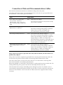
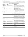
Connection of Data and Telecommunications Cables
Data and telecommunication interfaces are classified according to their safety status.
The following table lists the status of several standard interfaces. If the status of a given port differs from
the standard one, a notice will be given in the manual.
Ports
Safety Status
V.11, V.28, V.35, V.36, RS-530,
X.21, 10 BaseT, 100 BaseT,
Unbalanced E1, E2, E3, STM, DS-2,
DS-3, S-Interface ISDN, Analog voice
E&M
SELV
xDSL (without feeding voltage),
Balanced E1, T1, Sub E1/T1
TNV-1 Telecommunication Network Voltage-1:
FXS (Foreign Exchange Subscriber)
TNV-2 Telecommunication Network Voltage-2:
Safety Extra Low Voltage:
Ports which do not present a safety hazard. Usually
up to 30 VAC or 60 VDC.
Ports whose normal operating voltage is within the
limits of SELV, on which overvoltages from
telecommunications networks are possible.
Ports whose normal operating voltage exceeds the
limits of SELV (usually up to 120 VDC or telephone
ringing voltages), on which overvoltages from
telecommunication networks are not possible. These
ports are not permitted to be directly connected to
external telephone and data lines.
FXO (Foreign Exchange Office), xDSL
(with feeding voltage), U-Interface
ISDN
TNV-3 Telecommunication Network Voltage-3:
Ports whose normal operating voltage exceeds the
limits of SELV (usually up to 120 VDC or telephone
ringing voltages), on which overvoltages from
telecommunication networks are possible.
Always connect a given port to a port of the same safety status. If in doubt, seek the assistance of a
qualified safety engineer.
Always make sure that the equipment is grounded before connecting telecommunication cables. Do
not disconnect the ground connection before disconnecting all telecommunications cables.
Some SELV and non-SELV circuits use the same connectors. Use caution when connecting cables.
Extra caution should be exercised during thunderstorms.
When using shielded or coaxial cables, verify that there is a good ground connection at both ends. The
earthing and bonding of the ground connections should comply with the local codes.
The telecommunication wiring in the building may be damaged or present a fire hazard in case of
contact between exposed external wires and the AC power lines. In order to reduce the risk, there are
restrictions on the diameter of wires in the telecom cables, between the equipment and the mating
connectors.
Caution
Attention
To reduce the risk of fire, use only No. 26 AWG or larger telecommunication line cords.
Pour réduire les risques s’incendie, utiliser seulement des conducteurs de
télécommunications 26 AWG ou de section supérieure.
Some ports are suitable for connection to intra-building or non-exposed wiring or cabling only. In such
cases, a notice will be given in the installation instructions.
Do not attempt to tamper with any carrier-provided equipment or connection hardware.
Electromagnetic Compatibility (EMC)
The equipment is designed and approved to comply with the electromagnetic regulations of major
regulatory bodies. The following instructions may enhance the performance of the equipment and will
provide better protection against excessive emission and better immunity against disturbances.
A good earth connection is essential. When installing the equipment in a rack, make sure to remove all
traces of paint from the mounting points. Use suitable lock-washers and torque. If an external
grounding lug is provided, connect it to the earth bus using braided wire as short as possible.
The equipment is designed to comply with EMC requirements when connecting it with unshielded
twisted pair (UTP) cables. However, the use of shielded wires is always recommended, especially for
high-rate data. In some cases, when unshielded wires are used, ferrite cores should be installed on
certain cables. In such cases, special instructions are provided in the manual.
Disconnect all wires which are not in permanent use, such as cables used for one-time configuration.
The compliance of the equipment with the regulations for conducted emission on the data lines is
dependent on the cable quality. The emission is tested for UTP with 80 dB longitudinal conversion loss
(LCL).
Unless otherwise specified or described in the manual, TNV-1 and TNV-3 ports provide secondary
protection against surges on the data lines. Primary protectors should be provided in the building
installation.
The equipment is designed to provide adequate protection against electro-static discharge (ESD).
However, it is good working practice to use caution when connecting cables terminated with plastic
connectors (without a grounded metal hood, such as flat cables) to sensitive data lines. Before
connecting such cables, discharge yourself by touching earth ground or wear an ESD preventive wrist
strap.
FCC-15 User Information
This equipment has been tested and found to comply with the limits of the Class A digital device,
pursuant to Part 15 of the FCC rules. These limits are designed to provide reasonable protection
against harmful interference when the equipment is operated in a commercial environment. This
equipment generates, uses and can radiate radio frequency energy and, if not installed and used in
accordance with the Installation and Operation manual, may cause harmful interference to the radio
communications. Operation of this equipment in a residential area is likely to cause harmful
interference in which case the user will be required to correct the interference at his own expense.
Canadian Emission Requirements
This Class A digital apparatus meets all the requirements of the Canadian Interference-Causing
Equipment Regulation.
Cet appareil numérique de la classe A respecte toutes les exigences du Règlement sur le matériel
brouilleur du Canada.
Warning per EN 55022 (CISPR-22)
Warning
This is a class A product. In a domestic environment, this product may cause
radio interference, in which case the user will be required to take adequate
measures.
Avertissement
Cet appareil est un appareil de Classe A. Dans un environnement résidentiel, cet
appareil peut provoquer des brouillages radioélectriques. Dans ces cas, il peut
être demandé à l’utilisateur de prendre les mesures appropriées.
Achtung
Dieses ist ein Gerät der Funkstörgrenzwertklasse A. In Wohnbereichen können
bei Betrieb dieses Gerätes Rundfunkströrungen auftreten, in welchen Fällen der
Benutzer für entsprechende Gegenmaßnahmen verantwortlich ist.
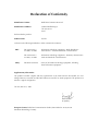
Declaration of Conformity
Manufacturer's Name:
RAD Data Communications Ltd.
Manufacturer's Address:
24 Raoul Wallenberg St.
Tel Aviv 69719
Israel
declares that the product:
Product Name:
FCD-E1
conforms to the following standard(s) or other normative document(s):
EMC:
Safety:
EN 55022:1998 +
A1:2000, A2:2003
Information technology equipment – Radio disturbance
characteristics – Limits and methods of measurement.
EN 55024:1998 +
A1:2001, A2:2003
Information technology equipment – Immunity characteristics–
Limits and methods of measurement.
EN 60950 (1992/93)
Safety of information technology equipment, including
electrical business equipment.
Supplementary Information:
The product herewith complies with the requirements of the EMC Directive 89/336/EEC, the Low
Voltage Directive 73/23/EEC and the R&TTE Directive 99/5/EC for wired equipment. The product was
tested in a typical configuration.
Tel Aviv, March 17, 2005
Haim Karshen
VP Quality
European Contact: RAD Data Communications GmbH, Otto-Hahn-Str. 28-30, 85521
Ottobrunn-Riemerling, Germany
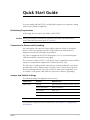
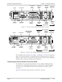
Quick Start Guide
If you are familiar with the FCD-E1, use this guide to prepare it for operation, starting
from its factory-default configuration.
Preliminary Preparations
At this stage, do not connect any cables to the FCD-E1.
Caution Before performing the preliminary preparation procedures described below,
review the safety precautions given in Section 2.1.
Connection to Power and Grounding
Any interruption of the protective (grounding) conductor (inside or outside the
device) or disconnecting the protective earth terminal can make the device
dangerous. Intentional interruption is prohibited.
AC power is supplied to the FCD-E1 through the 5-foot (1.5m) standard power
cable terminated in a standard 3-prong plug.
The connection of the FCD-E1 to a DC power source is permanent and is made by
means of a terminal block adapter that is inserted in the DC inlet.
The AC power cord plug must be inserted in an outlet provided with a protective
ground (earth) contact, whereas when using DC power it is necessary to ground
the AD grounding terminal. The protective action must not be negated by use of
an extension cord (power cable) without a protective conductor (grounding).
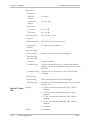
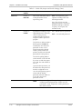
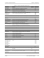
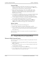
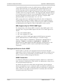
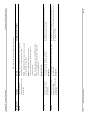
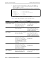
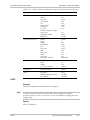
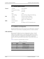
Jumper and Switch Settings
The following settings are shipped from the factory:
Component
Setting
Default Value
Main Board
Ground
Signal Ground connected to Frame Ground
Main Link Interface
Balanced Interface
Alarm Relay
DCD, CTS
Front Panel Buttons
Enabled
Clock Polarity
Normal
Sublink Interface
Balanced Interface
Sublink Board
If you need to change any of the default values, see Chapter 2 - Setting Jumpers
and Switches.
FCD-E1
1
Quick Start Guide
Installation and Operation Manual
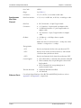
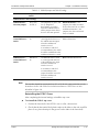
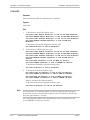
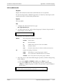
Cable Connections
Refer to the site installation plan, and connect the prescribed cables to the FCD-E1
ports:
Note
Cable
Connect to …
Main link cable
E1/T1 MAIN connector
Sublink cable (optional)
E1/T1 SUB connector
Data channel 1 cable
CH1 connector
Data channel 2 cable (optional)
CH2 connector
Ethernet cable
10/100BASE-T connector
When using adapter cables for the data channels, first connect the adapter cable to
the data channel connector, and then connect the user’s data cable to the adapter
connector.
When ready, apply power to the FCD-E1.
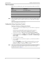
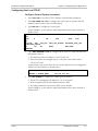
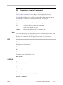
Configuration Using a Supervisory Terminal
Starting a Preliminary Configuration Session
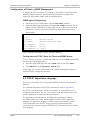
1. Connect a terminal to the CONTROL DCE port on the FCD-E1 rear panel (use
a straight cable).
You may use any standard ASCII terminal (dumb terminal or personal
computer emulating an ASCII terminal) equipped with an RS-232
communication interface. Make sure to use VT-100 terminal emulation.
2. Configure the terminal for 19.2 kbps, one start bit, eight data bits, no parity,
and one stop bit. Select the full-duplex mode, echo off, and disable any type
of flow control.
3. Connect the FCD-E1 to power.
4. Press the <Enter> key several times in sequence: you should see the FCD-E1
prompt, FCD>.
If you see PASSWORD> and the FCD-E1 default password has not yet been
changed, type RAD and then press <Enter> to obtain the prompt. If your
password is accepted, you will see the FCD-E1 prompt.
Note
2
If you cannot establish communication with the FCD-E1, reset FCD-E1 CONTROL
port parameters to the factory defaults using the internal switch SW2 using the
procedure described in Chapter 2.
FCD-E1
Installation and Operation Manual
Quick Start Guide
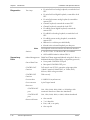
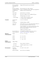
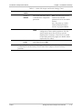
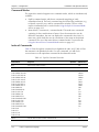
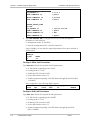
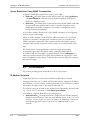
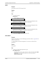
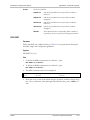
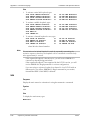
Configuration Procedure
Perform the following actions in the order given below.
Step
Action
Use the Command
1
Reset the database to the default parameters
INIT DB
2
Define the terminal control codes
DEF TERM
3
Configure the supervisory port
DEF SP
DEF CALL
4
Set FCD-E1 system time and date
TIME
DATE
5
Configure system parameters
DEF SYS
6
Configure the main link parameters
DEF ML
7
Configure the sub link parameters (optional)
DEF SL
8
Configure the data channel parameters
DEF CH 1
DEF CH 2 (when
installed)
9
Define the general system parameters
DEF
DEF
DEF
DEF
DEF
10
Define the alarm handling parameters
DEF AR
DEF ALM MASK
NAME
NODE
PWD
AGENT
MANAGER LIST
FCD-E1 is now ready for operation.
3
Quick Start Guide
4
Installation and Operation Manual
FCD-E1
Contents
Chapter 1. Introduction
1.1 Overview..................................................................................................................... 1-1
Product Options ................................................................................................................... 1-1
Application ........................................................................................................................... 1-2
Features................................................................................................................................ 1-2
1.2 Physical Description..................................................................................................... 1-8
1.3 Functional Description................................................................................................. 1-9
Functional Block Diagram ..................................................................................................... 1-9
Bus Functions ..................................................................................................................... 1-10
Main Link Interface............................................................................................................. 1-10
LIU (Line Interface Unit) ..................................................................................................... 1-11
Sublink Interface................................................................................................................. 1-13
Data Channels .................................................................................................................... 1-13
Ethernet Interface ............................................................................................................... 1-14
Management Subsystem ..................................................................................................... 1-15
Power Supply Subsystem .................................................................................................... 1-15
Timing Considerations ........................................................................................................ 1-15
System Management Considerations ................................................................................... 1-18
Alarm Collection................................................................................................................. 1-26
1.4 Technical Specifications............................................................................................. 1-27
Chapter 2. Installation and Setup
2.1 Introduction................................................................................................................. 2-1
2.2 Site Requirements and Prerequisites ............................................................................ 2-1
Electromagnetic Compatibility Considerations ....................................................................... 2-2
2.3 Package Contents ........................................................................................................ 2-2
2.4 Equipment Needed ..................................................................................................... 2-2
2.5 Setting the Internal Jumpers and Switches.................................................................... 2-3
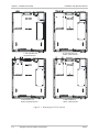
FCD-E1 Printed Circuit Boards .............................................................................................. 2-3
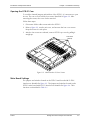
Opening the FCD-E1 Case .................................................................................................... 2-5
Main Board Settings .............................................................................................................. 2-5
Sublink Interface Board Settings .......................................................................................... 2-12
2.6 Connecting the Cables............................................................................................... 2-14
Connecting the Electrical Main Link and Sublink ................................................................. 2-15
Connecting the Management Ports...................................................................................... 2-18
Connecting the Power ........................................................................................................ 2-18
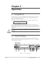
Chapter 3. Operation
3.1 Turning FCD-E1 On..................................................................................................... 3-1
3.2 Controls and Indicators ................................................................................................ 3-1
Organization of LCD............................................................................................................. 3-2
Information Displayed on the LCD........................................................................................ 3-4
Using the Front Panel Push Buttons....................................................................................... 3-4
Normal Indications ............................................................................................................... 3-5
3.3 Default Settings............................................................................................................ 3-6
Checking Current Operating Configuration............................................................................ 3-6
FCD-E1
i
Table of Contents
Installation and Operation Manual
3.4 Configuration Alternatives............................................................................................ 3-7
Connecting Supervision Terminals......................................................................................... 3-8
Connecting Alarm Monitoring Terminals................................................................................. 3-9
Connecting Telnet Hosts ....................................................................................................... 3-9
Connecting SNMP Management ......................................................................................... 3-10
3.5 Local Configuration Setup Procedure......................................................................... 3-10
3.6 Turning FCD-E1 Off................................................................................................... 3-12
Chapter 4. Configuration
4.1 Configuration Sequence .............................................................................................. 4-1
4.2 Introduction................................................................................................................. 4-2
Configuration and Management Activities ............................................................................. 4-2
Checking Current Operating Configuration............................................................................ 4-3
4.3 Preliminary Configuration ............................................................................................ 4-5
Preparation of FCD-E1.......................................................................................................... 4-5
Preparation of Supervision Terminal...................................................................................... 4-5
Initial Configuration .............................................................................................................. 4-5
Configuration of Terminals .................................................................................................... 4-6
Configuration of Telnet or SNMP Management ..................................................................... 4-7
4.4 FCD-E1 Supervision Language ..................................................................................... 4-7
Command Modes ................................................................................................................. 4-8
Index of Commands ............................................................................................................. 4-8
4.5 Using the Explicit Command Mode............................................................................ 4-15
Explicit Mode Command Syntax ......................................................................................... 4-15
Command Options ............................................................................................................. 4-15
Command Protocol............................................................................................................. 4-16
4.6 Using the Menu-Driven Command Mode.................................................................. 4-17
Mnemonic Mode Command Syntax.................................................................................... 4-17
Using the Mnemonic Mode ................................................................................................ 4-18
4.7 Supervision Terminal Operating Instructions .............................................................. 4-21
Starting a Single FCD-E1Session .......................................................................................... 4-21
Starting a Multiple FCD-E1Session....................................................................................... 4-22
Control Sessions.................................................................................................................. 4-22
Ending a Control Session..................................................................................................... 4-23
Chapter 5. Configuring Typical Applications
5.1 Configuring the FCD-E1 Application ............................................................................ 5-1
5.2 Outline of General Configuration Procedure................................................................ 5-1
5.3 Configuration Example ................................................................................................ 5-2
Configuring the Local FCD-E1 ............................................................................................... 5-3
Configuring the Remote FCD-E1 ........................................................................................... 5-6
Chapter 6. Troubleshooting and Diagnostics
6.1 Monitoring Performance .............................................................................................. 6-1
Displaying the Performance Data on the Front Panel LCD ..................................................... 6-1
Resetting the Performance Data Registers.............................................................................. 6-2
Displaying the Performance Data on a Supervision Terminal ................................................. 6-2
6.2 Detecting Errors ........................................................................................................... 6-4
Power-Up Self-Test ............................................................................................................... 6-4
Configuration Error Messages ................................................................................................6-5
ii
FCD-E1
Installation and Operation Manual
Table of Contents
6.3 Handling Alarms .......................................................................................................... 6-7
Alarm Display ....................................................................................................................... 6-7
Alarm Messages .................................................................................................................... 6-8
Working with Alarm Buffer.................................................................................................. 6-14
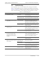
6.4 Troubleshooting......................................................................................................... 6-15
6.5 Testing FCD-E1.......................................................................................................... 6-16
Operating Loopbacks from the Front Panel ......................................................................... 6-16
Operating Loopbacks from a Control Terminal .................................................................... 6-17
User-Controlled Loopback Tests.......................................................................................... 6-17
6.6 Frequently Asked Questions ...................................................................................... 6-23
6.7 Technical Support...................................................................................................... 6-23
Appendix A. Pinouts
Appendix B. SNMP Management
Appendix C. Operating Environment
Appendix D. Command Language
Appendix E. IR-ETH Interface Module
Appendix F. IR-ETH/Q Interface Module
FCD-E1
iii
Table of Contents
iv
Installation and Operation Manual
FCD-E1
Chapter 1
Introduction
1.1
Overview
FCD-E1 is an access unit for E1 (2.048 Mbps) and fractional E1 services that
supports advanced management capabilities, including SNMP.
FCD-E1 is a standalone compact unit, intended for installation on desktops or
shelves. Unit height is 1U (1.75-inch). Optional rack-mount adapter kits enable the
installation of one or two FCD-E1 units in a 19-inch rack.
The wide range of user ports supported by FCD-E1 enables it to serve as an access
unit and integrating multiplexer for E1 and fractional E1 services.
FCD-E1 can also be operated in an unframed mode. In this mode, FCD-E1 accepts
a 2048 kbps data stream through a synchronous data port and converts it to an
ITU-T Rec. G.703 unframed signal for transport over the E1 main link. Thus,
FCD-E1 can also serve as an interface converter and high-speed, short-distance
modem.
Product Options
FCD-E1 is available in several versions that differ in the number and type of user
ports:
Note
FCD-E1
•
One or two synchronous data channels. The data channels can be ordered
with V.35, V.36/RS-449, or X.21 interfaces.
•
One synchronous data channel (with V.35, V.36/RS-449, or X.21 interface)
and one Ethernet 10BaseT interface with internal remote bridge (bridge
function can be enabled or disabled by the user). The bridge can be ordered
with (IR-ETH/Q) or without (IR-ETH) VLAN support. In this version the
Ethernet port is always the upper one (Channel 2), and the synchronous data
channel is the lower one (Channel 1).
•
One E1 sublink, which provides a drop-and-insert capability, and enables the
connection of fractional E1 equipment and digital PBXs to the E1 main link.
In this manual, the generic term FCD-E1 is used when the information is applicable
to all FCD-E1 versions. Information applicable to a specific version is explicitly
identified.
Overview
1-1
Chapter 1 Introduction
Installation and Operation Manual
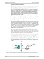
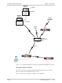
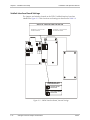
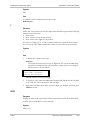
Application
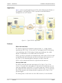
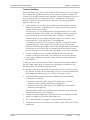
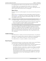
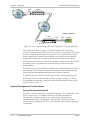
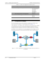
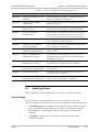
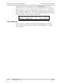
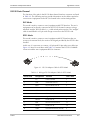
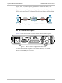
Figure 1-1 shows a typical application for FCD-E1, which illustrates the utilization of
its capabilities. In this application, FCD-E1 provides an extended Ethernet
management over an E1 network.
Figure 1-1. Typical FCD-E1 Application
Features
Main Link Interfaces
The interface supports the standard E1 framing formats, i.e., comply with the
requirements of ITU-T Rec. G.704 and G.732, and support both G732N framing
(2 per multiframe) and G732S framing (16 frames per multiframe, also called
timeslot 16 multiframes), in accordance with user's selection.
FCD-E1 can also be operated in an unframed mode. In this mode, FCD-E1 accepts
an 2048 kbps data stream through a synchronous data port and converts it to an
ITU-T Rec. G.703 unframed signal for transport over the E1 main link.
FCD-E1 can be ordered with electrical or optical main link interfaces.
Electrical Main Link
The FCD-E1 main link meets the requirements of ITU-T Rec. G.703, G.704,
G.706, G.732, and G.823, and supports G732N and G732S multiframes (2 or 16
frames per multiframe, respectively), in accordance with user’s selection. The link
also supports the CRC-4 function in accordance with ITU-T Rec. G.704. The main
link can also operate in the unframed mode, to generate an ITU-T Rec. G.703
unframed signal.
The framing mode, as well as the use of the CRC-4 function, is user-selectable.
1-2
Overview
FCD-E1
Installation and Operation Manual
Chapter 1 Introduction
For FCD-E1 versions with sublink, the framing mode and the CRC-4 function can
be separately selected for the main link and sublink; therefore, FCD-E1 can also
serve as a framing converter between the user’s equipment connected to the
sublink and the network. For example, FCD-E1 enables the connection of
equipment that does not support the CRC-4 function to networks which use this
function.
The main link has two line interfaces:
•
120Ω balanced line interface, terminated in an eight-pin RJ-45 (ISO 10173)
connector.
•
75Ω unbalanced interface terminated in two BNC coaxial connectors.
The operating mode of the main link interface, DSU or LTU, is user-selectable. In
the DSU mode, the maximum line attenuation is up to 10 dB; in the LTU mode, the
maximum line attenuation is up to 36 dB, which for typical cables translates to a
range of up to 2 km. This allows FCD-E1 to be placed at a distance of up to 2 km
from the transmission equipment.
Optical Main Link
A wide range of fiber optic interfaces complying with ITU-T Rec. G.921 and G.956
is available for FCD-E1, to optimally meet a wide range of system requirements.
FCD-E1 can be ordered with fiber optic interface with laser transmitter for
operation over 62.5/125 micron multimode fibers (typical attenuation –3.5
dB/km), as well as over low-loss 9/125-micron single-mode fibers (typical
attenuation of 0.4 dB/km at 1310 nm, and 0.25 dB/km at 1550 nm). Each option
can be ordered with ST or FC/PC connectors.
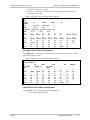
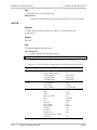
Table 1-1 provides information on the characteristics of the optical subsystem,
including the maximum range over typical fiber optic cable.
Table 1-1. Fiber Optic Interface Characteristics
Wavelength Fiber Type Power
Receiver
Coupled Sensitivity
into Fiber
[dBm]
[nm]
[dBm]
[µm]
Optical Maximum
Budget Receiver
Input Power
[dBm]
[dB]
Receiver
Dynamic
Range
[dB]
Typical
Maximum
Range
[km] [mi]
850
62.5/125
multimode
–18
–38
20
–10
28
5
3
1310
9/125
–12
single-mode
–34
22
–12
28
55
34
1550
9/125
–12
single-mode
–34
22
–12
28
88
55
All the fiber optic interface options offer high performance and have a wide
dynamic range, which ensures that the receiver will not saturate even when using
short fiber optic cables. Saturation is caused when the optical power applied to the
receiver exceeds its maximum allowed input power, and results in very high bit
error rates.
FCD-E1
Overview
1-3
Chapter 1 Introduction
Installation and Operation Manual
The optical interface fully emulates the operation of a standard E1 electrical main
link module, including the use of an HDB3-encoded optical signal, and AIS
transmission.
Sublink Interface
FCD-E1 can be ordered with a sublink interface. The sublink interface is always an
electrical interface. Its characteristics are identical to the characteristics of the
electrical main link interface, except that it does not support the unframed mode.
Data Channel Interfaces
The FCD-E1 synchronous data channel can be ordered with one of the following
types of interfaces: RS-530, V.35, X.21, and V.36/RS-449. Each data port is
terminated in a 25-pin D-type female connector.
The conversion between the 25-pin channel interface connector and the standard
V.35, X.21 or V.36 interface connectors is made by means of adapter cables:
•
V.36/RS-449 interface: the adapter cable is terminated in a 37-pin D-type
female connector.
•
V.35 interface: the adapter cable is terminated in a 34-pin female connector.
•
X.21 interface: the adapter cable is terminated in a 15-pin D-type female
connector.
Suitable adapter cables can be ordered from RAD (see Error! Bookmark not
defined. and Chapter 2).
The FCD-E1 synchronous data port supports the following control lines:
•
RTS - input from the locally connected user’s equipment.
•
CTS - the user can permanently set the CTS line in the active state, or can
make the CTS line follow the RTS line.
•
DSR - the DSR line is always active when the FCD-E1 is powered, except
when a remote main link test loopback is activated.
•
DCD - the DCD line is active when the FCD-E1 main link interface is
synchronized.
Ethernet Interfaces
The 10BaseT Ethernet interface complies with IEEE 802.3 and Ethernet V.2
standards. It is terminated in an RJ-45 shielded connector that operates over UTP
media.
To provide control over the Ethernet traffic flowing through the main link, the
Ethernet interface can be ordered with one of the following options:
•
Full-feature remote bridge, IR-ETH. You can disable the bridge, to operate the
FCD-E1 link as a LAN extender (repeater).
•
Full-feature remote bridge with VLAN support, IR-ETH/Q. You can disable the
bridge, to operate the FCD-E1 link as a LAN extender (repeater).
Both bridges can operate at wire speed. For further information on the IR-ETH and
IR-ETH/Q interfaces, refer to Appendix E and Appendix F, respectively.
1-4
Overview
FCD-E1
Installation and Operation Manual
Chapter 1 Introduction
Timeslot Handling
When operating in any of the framed modes, FCD-E1 allows the user to configure
the routing of the individual timeslots for each channel, and for the sublink. The
routing can be modified during system operation, without disrupting the service to
users of timeslots that are not rerouted. FCD-E1 automatically connects the
timeslots in both the receive and transmit directions. The routing capabilities
depend on the port type:
•
For the sublink, you can select the timeslots to be transferred between the
sublink and main links. A sublink timeslot is always routed to the main link
timeslot with the same number.
You can specify, for each sublink timeslot, the payload type (voice or data)
carried in the timeslot. This enables correct handling of timeslots and of the
associated signaling information during alarm conditions. An additional
difference between voice and data timeslots is that voice timeslots can be
connected only to a link, which uses G732S multiframes.
To expedite the routing, FCD-E1 supports a “bundle” routing mode, called
“sequential bundle” routing mode. One “bundle” (group of consecutive
timeslots, identified by the number of the starting timeslot and the total number
of timeslots) can be routed to the corresponding main link timeslots, where
they are inserted in the main link frame sequentially, in consecutive timeslots.
•
For data channels, the user can either individually select the main link
timeslots in which the user’s data is to be inserted, or can use the “bundle”
routing mode. Timeslots connected to data channels are always defined as
data timeslots.
To help you route correctly timeslots, FCD-E1 automatically checks the validity of
the user’s inputs, and reports, by means of error messages, inconsistencies and
invalid selections. The conditions reported include:
•
Attempt to allocate to user’s traffic timeslots that must be reserved for system
use: timeslot 16 when G732S multiframes are used, or a timeslot dedicated to
the management traffic between two FCD-E1 connected in a link.
•
Total bandwidth requested exceeds the available main link bandwidth:
Maximum 31 timeslots
Maximum 30 timeslots when using G732S multiframes or G732N
multiframes with a timeslot dedicated to management
Maximum 29 timeslots when using G732S multiframes and a timeslot
dedicated to management.
The bandwidth carried by the available timeslots depends on the basic data
rate selected by the user (56 or 64 kbps).
FCD-E1
•
Number of timeslots assigned to a data channel does not match the number
required to support the specified channel data rate.
•
Two or more timeslots are mapped to any given main link timeslot.
•
Timeslots specified as voice timeslots are routed to a link, which uses G732N
multiframes.
Overview
1-5
Chapter 1 Introduction
Installation and Operation Manual
Timing
Multiple clock source selection provides maximum system timing flexibility, and
supports hierarchical dissemination of timing information.
System Timing
Internally, FCD-E1 uses one system timing source (clock). This system clock
determines the transmit timing of all the E1 links and data ports, and the timing of
most other signal processing operations.
To achieve maximum flexibility in system integration and enable hierarchical
distribution of timing in the system, FCD-E1 enables the user to select the source
to which the master clock is locked. The available options are as follows:
Note
•
System clock source locked to the recovered receive clock of the main link, or
sublink (when available).
•
System clock source locked to an external clock (e.g., the transmit clock
applied to a user-selected data port). The timing mode of the selected port
must be DTE2.
The DTE2 mode is not available on channels with X.21 interfaces, or on the
Ethernet interface.
•
System clock source locked to the internal crystal oscillator, which has an
accuracy of ±50 ppm.
In addition to the selection of a main clock source, you can specify a fallback
source, which is automatically selected in case the main source fails. The fail
criteria are loss of the receive signal on the port selected as the main source, or
inactive RTS line on the selected data port. The internal oscillator always serves as
a fallback source, which is automatically selected in case the other selected timing
sources fail.
Main Link Timing
FCD-E1 recovers the main link receive clock signal, and uses it as the timing source
for the receive path. The main link transmit timing source, which is derived from
the main system clock, can be locked to one of the following sources:
•
Recovered receive clock
•
External clock signal (derived from one of the synchronous data channels or
from the sublink)
•
Internal oscillator.
Sublink Timing
The sublink transmit clock is always locked to the main link transmit clock, and the
receive clock is recovered from the incoming sublink signal.
The receive clock can be selected as an external clock source for the main link
transmit clock.
Synchronous Data Port Timing
The FCD-E1 data port has three timing modes:
1-6
Overview
FCD-E1
Installation and Operation Manual
Chapter 1 Introduction
•
DCE – the FCD-E1 data port provides transmit and receive clock, derived from
the main system clock, for the user’s equipment connected to the data port.
•
DTE1 – the FCD-E1 data port sends the receive data accompanied by the
receive clock, derived from the main system clock, to the user’s equipment
connected to the data port, and accepts user’s data according to the user’s
equipment transmit clock.
•
DTE2 – FCD-E1 transmits and receives data according to the clock signals
provided by the equipment connected to the data port. When using this
clocking mode, the main link rate must be locked to the clock signal supplied
by the user’s data port interface. The DTE2 mode is not available on channels
with X.21 and Ethernet interfaces.
FCD-E1 provides a FIFO buffer for the data channel, to absorb timing
differences.
FIFO size is generally automatically selected, however in the DTE2 timing
mode, the user can select FIFO size to meet specific system requirements.
Ethernet Port Timing
The timing of the Ethernet processing circuits is always derived from the main
system clock (“DCE” timing). This port cannot be selected as a timing source.
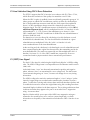
Management
FCD-E1 is designed for unattended operation. The FCD-E1 configuration, that is,
the complete collection of its operating parameters, is determined by a database
stored in non-volatile memory.
The FCD-E1 database management, as well as the other configuration, test, and
monitoring activities (equipment status reading, alarm status and history, activation
of test loops, reading of performance statistics, etc.) can be performed in three ways:
•
Supervision Terminal − A “dumb” ASCII terminal connected to an RS-232
port of the FCD-E1 (or a PC running a terminal emulation program), controlled
by the program stored in the FCD-E1, can be used as a supervision terminal.
The terminal can also be connected through a modem link, to enable dial-in
from a remote location. The FCD-E1 supports both point-to-point and
multidrop connections.
•
SNMP Management − The SNMP management capability enables fully
graphical, user-friendly management using the RADview network management
stations offered by RAD, as well as management by other SNMP-based
management systems.
•
Telnet − Remote management is also possible using the Telnet communication
protocol, which uses TCP/IP communication, without the SNMP service.
Telnet support enables a remote IP host to control the operation of the
FCD-E1 using functions identical to those provided by a supervision terminal.
The communication between the management system and FCD-E1 can take place
out-of-band (by connecting to the serial or Ethernet management ports) or inband
(through the main and/or sublink). FCD-E1 includes a proprietary IP router for
management traffic. This function enables FCD-E1 to transfer management traffic
generated by, or addressed to, other FCD-E1 units, and also inband management
FCD-E1
Overview
1-7
Chapter 1 Introduction
Installation and Operation Manual
traffic addressed to other RAD equipment that operates over E1 links, such as the
Megaplex modular TDM E1/T1 multiplexers, DXC multiservice access nodes, etc.
Alarms
FCD-E1 stores alarms detected during its operation in a buffer that can hold up to
100 alarms. During regular operation, an alarm indicator on the front panel lights
when alarms are present in the alarm buffer, to notify the local operator that alarm
conditions have been detected. The local operator can then review the contents of
the alarm buffer using the supervision terminal, a Telnet host, or a management
station.
In addition to the alarm buffer, the front-panel LED indicators display in real time
the status of the main link and sublink, and alert when test loops are present in the
system. Also, the FCD-E1 version with two RS-232 interfaces can automatically
report alarms to a remote terminal using a dial-up modem.
FCD-E1 can provide an alarm indication by means of an alarm relay (dry contacts),
which enables remote signaling of alarm conditions when FCD-E1 is located far from
the personnel in charge for its proper operation.
The alarm relay has a pair of change-over dry contacts: the normally-open (NO)
contacts close in case of alarm, and the normally-closed (NC) contacts open in
case of alarm. The alarm contacts are floating with respect to the signal and chassis
grounds of the FCD-E1.
Statistics Collection
When CRC-4 is used, FCD-E1 collects and stores E1 port statistics in compliance
with ITU-T Rec. G.706. These statistics can be retrieved by the management
functions, e.g., through the supervisory port, and via inband management.
Diagnostics
FCD-E1 has comprehensive diagnostics capabilities that include user-activated
local and remote loopbacks on the data ports, on the sublink and main link.
Transmitting an inband code can activate the remote data port loopbacks. To
enable testing of marginal links, FCD-E1 also offers bit error rate (BER) testing on
the synchronous data channels, using a locally generated pseudorandom
sequence. To provide compatibility with other BER testing equipment, the user
can select the pseudorandom pattern.
Maintenance is further enhanced by an automatically performed power-up
self-test, which provides circuit-level diagnostics data.
1.2
Physical Description
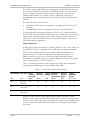
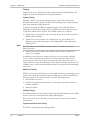
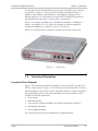
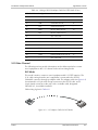
A 3D view of FCD-E1 is shown in Figure 1-2.
The front panel includes push buttons, LEDs, an LCD display and the supervision
terminal connector for controlling and monitoring the FCD-E1 operation. For
details, see Chapter 3.
1-8
Physical Description
FCD-E1
Installation and Operation Manual
Chapter 1 Introduction
The rear panel of the unit includes the power switch and all the user connectors.
For details see Chapter 2. The rear panel of the Ethernet bridge includes, in
addition, status indicators and switches for controlling the operation of the
Ethernet interface. The LED indications for the IR-ETH and IR-ETH/Q interfaces
are described in the Appendix E and Appendix F, respectively.
FCD-E1 is a compact standalone unit, intended for installation on desktops or
shelves. Unit height is 1U (1.75 inches). An optional rack-mount adapter kit
enables the installation of an FCD-E1 unit in a 19-inch rack.
FCD-E1 is cooled by free air convection, and does not include internal fans.
Figure 1-2. FCD-E1 Unit
1.3
Functional Description
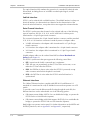
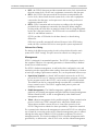
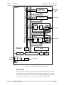
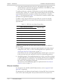
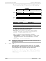
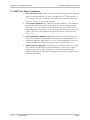
Functional Block Diagram
Figure 1-3 shows the functional block diagram version of the FCD-E1 system. The
FCD-E1 version shown in Figure 1-3 has an electrical main link interface. However,
the block diagram of the FCD-E1 version with optical interface is similar, except that
the bypass bridge option and the associated relays cannot be installed. FCD-E1
includes several main subsystems:
•
Chassis buses
•
Main link interface
•
User interface subsystem (Sublink, Data channel and Ethernet channel)
•
Management subsystem
•
Power supply subsystem.
The characteristics of the various subsystems are explained below.
FCD-E1
Functional Description
1-9
Chapter 1 Introduction
Installation and Operation Manual
Bus Functions
The FCD-E1 system performs its various functions by controlling the flow of data
among the various user and main link interfaces in accordance with the
application requirements.
The flow of data is performed through the FCD-E1 buses, as shown in Figure 1-3.
FCD-E1 comprises several buses:
•
TDM bus, which carries the data to the main link. The TDM bus serves as a
highway through which all the information processed by the FCD-E1 flows. The
information is deposited and collected in discrete time intervals, called timeslots
(one timeslot supports a data rate of 64 kbps – see Appendix C). The TDM bus
consists of two lines:
TSER line – carries the transmit data to the main link interface. The other
interfaces deposit data on this line, in the timeslots specified by the
management subsystem.
RSER line – carries the data received by the main link interface. The other
interfaces read their data from the timeslots specified by the management
subsystem.
Each FCD-E1 port deposits payload information received through its external
interface on one TDM bus line, and simultaneously collects the information to be
sent through the external interface from the other line. Therefore, considerable
flexibility is available with respect to routing, because each port has access to all
the payload information, and can be instructed by the management subsystem to
read and write the desired information in the desired timeslots of the FCD-E1
TDM bus.
•
Clock bus, which carries the various clock signals used by the FCD-E1 system.
The FCD-E1 can lock its system clock (see the Timing section on page 1-6) to
various clock signals applied to its user ports, in accordance with the
application requirements.
•
Two management buses:
Address bus – carries routing information from the management subsystem
to the other subsystems.
Data Bus – carries the internal management data.
Main Link Interface
The characteristics of the main interface are described in Main Link on page 1-2.
The main functions of the main link interface are described below.
Framer
The transmit path of the framer generates the E1 frame structure transmitted by the
corresponding port, in accordance with the selected framing mode. The frame
structure is generated by combining the data retrieved from the prescribed timeslots of
the TSER line with the framing overhead. The TSER line may also carry inband
management data generated by the management subsystem when the main link
framing mode is G732S (G732N). Unused timeslots are filled with the idle code.
1-10
Functional Description
FCD-E1
Installation and Operation Manual
Chapter 1 Introduction
The receive path of the framer extracts the payload data, the inband management
data stream and demultiplexes the incoming E1 data stream.
The framer also collects performance statistics based on framing errors and errors
detected by the CRC-4 monitoring function, which can be read by the
management subsystem through the module management subsystem.
When the main link is operated in the unframed mode, the framer is bypassed. As
a result, the main link transparently transfers the data stream received from the
data channel. Since in the unframed mode the data channel is configured for
operation at a data rate of 2048 kbps, any other FCD-E1 ports must be
disconnected from the main link.
LIU (Line Interface Unit)
This section describes in detail the operation of the LIU for the electrical main link
interface. The functionality of the optical LIU is similar to that of the electrical LIU,
except that the interface transmits and receives optical signals (see Optical Main
Link on page 1-3).
Transmit Path
The transmit path of the LIU includes an HDB3 coder, which converts the NRZ
transmit data stream provided by the E1 framer to the line code specified for use
on E1 links, and then generates the E1 transmit signal in accordance with ITU-T
Rec. G.703.
FCD-E1
Functional Description
1-11
Chapter 1 Introduction
Installation and Operation Manual
FCD-E1
Data Channel
or Ethernet Interface
Data Channel
or Ethernet
Ports
Data Channel
Data Channel
Main Link
Framer
LIU
RSER
TSER
Main Link Port
Bypass
Bridge
(Option)
Management
Subsystem
Inband
Management
interface
Rear Panel Interface
(Serial Port
or Ethernet)
Fuse
Framer
Sublink Port
LIU
Data Bus
Address Bus
Clock Bus
Sublink
FCD-E1
Control Logic
LCD
Front Panel
Serial Port
Interface
POWER
AC Input
Power
Connector
Main
Power Supply
Internal Voltages
Figure 1-3. FCD-E1 Functional Block Diagram
Receive Path
The receive path of the LIU recovers the received E1 signal and the associated
clock signal. The recovered clock signal is used by other module circuits, and is
also applied on the clock bus. The recovered E1 signal is decoded by an HDB3
decoder, and sent to the receive path of the E1 framer in NRZ format.
1-12
Functional Description
FCD-E1
Installation and Operation Manual
Chapter 1 Introduction
The operating mode of the LIU receive path, DSU or LTU, is user-selectable.
The HDB3 decoder can provide performance statistics for evaluating line
transmission quality when the CRC-4 option is not used, by collecting data on the
bipolar violations (BPVs) detected in the incoming signal.
Bypass Relays
The bypass relays are normally energized, and connect the external E1 port lines to
the LIU.
When FCD-E1 is not operating, the relays are deenergized, and take the position
shown in Figure 1-3. In this case, for an FCD-E1 with a sublink, the transmit line of
the main link is connected through the optional bypass bridge to the receive path
of the sublink, and vice versa.
Notes
• The bypass relays are available only on electrical main link interface boards.
• The bypass bridge is a narrow printed circuit board installed between the main
link and sublink interface boards that plugs into special connectors located in the
center of each board. The bypass bridge is an option available upon order.
• The bypass bridge interconnects only the balanced interfaces.
The use of the bypass bridge is recommended when the FCD-E1 main and sublink
carry inband management traffic destined to additional equipment within the
network. This arrangement enables the management traffic to pass to the other
equipment, irrespective of the state of the FCD-E1. Note however that the bypass
option is useful only when the total attenuation of the lines connected in series
does not exceed the maximum attenuation that can be compensated for by the
other equipment.
Sublink Interface
The sublink interface is similar to the electrical main link interface, except that the
direction of flow of signals is different where the sublink receive data is applied on
the TSER line, and the sublink transmit data is collected from the RSER line.
The sublink interface is an option, installed in accordance with order.
Data Channels
The data channels operate as a synchronous port, which connects to the TDM bus
via a bus interface. The data channels perform two main functions:
•
In the output (receive) direction, the bus interface reads the payload data from
the appropriate timeslots of the TSER line, under the control of the
management subsystem, and generates a continuous n×56 kbps or n×64 kbps
data stream. The data stream is accompanied by a clock signal derived from
the internal FCD-E1 system clock.
The transmit data and clock signals are then applied to the channel interface,
which provides the interface to the external (user’s) equipment. The interface
can be ordered from one of the following options: RS-530, V.35, X.21, and
V.36/RS-449.
FCD-E1
Functional Description
1-13
Chapter 1 Introduction
•
Installation and Operation Manual
In the input (transmit) direction, the user’s data applied to the input of the
channel interface is placed in the appropriate timeslots of the RSER line, under
the control of the management subsystem.
To enable synchronous operation, FIFO buffers are used to absorb small timing
variations (jitter, wander, etc.). In all the data channel timing modes, the FIFO size
is automatically selected in accordance with the data channel rate, as listed in
Table 1-2. The values listed in Table 1-2 are selected in accordance with the limits
specified in the applicable standards.
In addition, when using the DTE2 mode, the FIFO size can also be manually
selected, to enable the user to increase FIFO size when the jitter exceeds the
expected limits.
Table 1-2. FIFO Size versus Data Channel Rate
Data Channel Rate (kbps)
FIFO Size (bits)
n × 56
n × 64
56
64
±16
112 and 168
128 and 192
±30
224 through 448
256 through 512
±52
504 through 896
576 through 1024
±72
952 through 1792
1088 through 1792
±52
1848 and 1904
1856 and 1920
±30
1960
1984
±16
In addition to payload data, the data channel interfaces handle two additional
types of signals:
•
Clock signals. The direction of the clock signals depends on the data channel
timing mode, DCE, DTE1, or DTE2. The timing modes are explained in the
Synchronous Data Port Timing section on page 1-6.
In the DTE2 mode, the clock signal applied to the transmit input is connected
to the clock bus and can be selected as an FCD-E1 system timing reference.
•
Handshaking signals. The handshaking signals are used to control the exchange
of signals with the user’s equipment, in accordance with the protocol applying
to the installed data channel interface. The handshaking is performed under
the control of the management subsystem.
The functions of the handshaking signals are explained in the Data Channel
Interfaces section on page 1-4.
Ethernet Interface
For description of the IR-ETH and IR-ETH/Q interfaces, refer to Appendix E and
Appendix F, respectively.
The timing mode of the Ethernet channel interface is always DCE, that is, the timing
of the receive and transmit paths is always locked to the FCD-E1 system clock.
1-14
Functional Description
FCD-E1
Installation and Operation Manual
Chapter 1 Introduction
Management Subsystem
The management subsystem controls the FCD-E1 operation, in accordance with its
operating software. The basic capabilities of the management subsystem are
presented in Management on page 1-7. The management subsystem also includes
an SNMP agent, and a proprietary IP router for SNMP management traffic.
The management subsystem exchanges information and sends commands through
several ports:
•
The communication with the various internal subsystems of the FCD-E1 is
performed through the management address and data buses. The subsystem
also controls the front-panel indicators, and the rear-panel alarm relay.
•
The communication with the supervision terminal is performed through the
front panel RS-232 serial port interface. This port is used to perform the initial
configuration of the FCD-E1, using any standard ASCII (“dumb”) terminal (or
PC running a basic communication or terminal emulation program). After the
initial configuration, the port can be used to control and monitor FCD-E1
operation.
•
In addition to the front-panel serial port (CONTROL DCE), FCD-E1 has an
additional port, located on the rear panel (CONTROL DTE). This port can be
used as an alarm reporting port (connected through a dial-up modem link to a
remote alarm monitoring terminal).
•
When inband management is enabled, the management subsystem transmits
and receives management traffic through the E1 ports. The communication
with the E1 ports is made through the TDM bus.
Power Supply Subsystem
FCD-E1 can be powered by 100 to 240 VAC, 50/60 Hz, or by -48 VDC, in
accordance with order. Figure 1-3 shows an AC-powered FCD-E1:
•
The AC input voltage passes through a protection fuse located in the AC input
connector, and through the POWER on/off switch (the DC-powered FCD-E1
does not include a fuse). The POWER switch includes an internal indicator that
lights when the FCD-E1 is turned on.
•
The AC input voltage is applied to the main power supply voltage, which
generates the regulated voltages required for the FCD-E1 internal circuits.
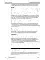
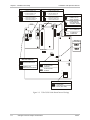
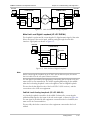
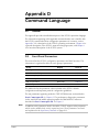
Timing Considerations
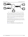
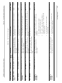
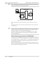
Main Link Timing Application
Figure 1-4 shows a typical application in which FCD-E1 is operated with the main
link as the timing reference source, and illustrates the flow of timing signals within
the system.
FCD-E1
Functional Description
1-15
Chapter 1 Introduction
Installation and Operation Manual
FCD-E1/1
User
DTE
CH 1
DCE
Timing
ML
Timing
FCD-E1/2
User
DTE
DCE
Timing
E1
Network
FCD-E1/1
DTE1
Timing
User
DTE
DCE
Timing
User
DTE
ML
Timing
CH 2
Master Timing
Source
Loopback
Timing
Figure 1-4. Main Link Timing, Flow of Timing Signals in a Typical Application
When using the main link as the timing reference, the data port must use DCE
timing. However, DTE1 timing can also be used, provided the user’s equipment
connected to the data channels operates with loopback timing, that is, the user’s
equipment must lock its transmit clock to the receive clock provided by FCD-E1.
FIFO buffers are used on the data ports, to absorb small timing variations (jitter,
wander, etc.). FIFO size is automatically selected in accordance with the data
channel rate, as listed in Table 1-2.
The main link timing mode is particularly suitable for FCD-E1 units connected to
an E1 network which has an accurate master timing source (e.g., PTT or national
network), because it enables locking the timing of the equipment connected to the
FCD-E1 units to the network timing.
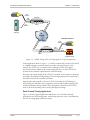
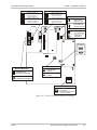
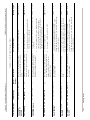
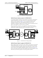
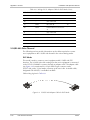
Sublink Timing Application
Figure 1-5 shows a typical application, which uses the sublink as the timing
reference source, and illustrates the flow of timing signals within the system.
1-16
Functional Description
FCD-E1
Installation and Operation Manual
User's DTE
Chapter 1 Introduction
Data
Channel
DCE
Timing
E1
Sublink
FCD-E1/S1
SL
Timing
Digital
Exchange
E1
Network
Customer Premises
Data
Channel
FCD-E1/S1
User's DTE
DCE
Timing
E1
Sublink
ML
Timing
PBX
(Loopback Timing)
Figure 1-5. Sublink Timing, Flow of Timing Signals in a Typical Application
In the application shown in Figure 1-5, a PBX is connected by a fractional E1 trunk
to a digital exchange, and must therefore use the exchange timing. For this
purpose, the FCD-E1/S1 connected to the exchange uses the clock signal
recovered from the sublink as the system timing reference, and the FCD-E1/S1
located on the customer’s premises uses main link timing.
Therefore, the system timing of the FCD-E1/S1 located on the customer’s premises
is locked to the digital exchange timing. The exchange timing is thus transferred to
the PBX located on the customer’s premises.
Note that the data channels of the two FCD-E1 units must use DCE timing (or
DTE1 timing, provided the user’s equipment operates with loopback timing). This
enables locking the timing of all the other equipment connected to the FCD-E1
units to the accurate timing source serving the digital exchange.
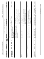
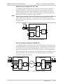
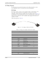
Data Channel Timing Application
Figure 1-6 shows a typical application which uses one of the data channels
operating in the DTE2 timing mode, as the timing reference source, and illustrates
the flow of timing signals within the system.
FCD-E1
Functional Description
1-17
Chapter 1 Introduction
Data
Network
Installation and Operation Manual
DTE2
Timing
FCD-E1
Data
Channel
E1
Network
Customer Premises
FCD-E1
DCE
Timing
Data
Channel
User's DTE
ML Timing
Figure 1-6. Data Channel Timing, Flow of Timing Signals in a Typical Application
In the application shown in Figure 1-6, the data equipment located on the
customer’s premises uses the FCD-E1 link to connect to a data network. Since data
networks include accurate timing sources and do not accept data whose timing
deviates significantly from the network timing, it is necessary to ensure that the
equipment located on the customer’s premises uses the data network timing.
For this purpose, the FCD-E1 connected to the data network uses the data channel
as its timing source, and therefore its main link timing is locked to the data
network timing.
The FCD-E1 located on the customer’s premises uses main link timing. As a result, its
system timing is also locked to the data network timing, and the network timing is
transferred to the data equipment located on the customer’s premises.
To optimize jitter performance, the FIFO size of a data channel operating in the
DTE2 mode can be selected manually (±16 bits, ±30 bits, ±52 bits, or ±72 bits).
The manually selected value cannot be less that the automatically selected value,
which are listed in Table 1-2.
System Management Considerations
System Management Method
The FCD-E1 system is designed for unattended operation. The configuration of the
FCD-E1 system, that is, a complete collection of operating parameters, is
determined by a database stored in non-volatile memory located in the
management subsystem. The database is automatically loaded upon FCD-E1
turn-on, thereby enabling the FCD-E1 to automatically return to its last operating
configuration.
1-18
Functional Description
FCD-E1
Installation and Operation Manual
Chapter 1 Introduction
In addition, FCD-E1 stores a set of factory-default parameters, which can be used
to start the configuration of a new FCD-E1 unit; the default parameters can also be
loaded in case the user’s database is corrupted.
FCD-E1 database management, as well as the other configuration, test, and
monitoring activities (equipment status reading, alarm status and history, activation
of test loops, reading of performance statistics, etc.) can be performed in three
ways:
•
Supervision Terminal. A “dumb” ASCII terminal (or a PC running a terminal
emulation program), connected to the front-panel RS-232 serial ports of the
management subsystem installed in the FCD-E1, can be used as a supervision
terminal. The connection can be made either directly, or through modem or
low-speed data links. The FCD-E1 system supports both point-to-point and
multidrop connections.
The program stored in the FCD-E1 management subsystem controls the
supervision terminal.
•
SNMP Management. The SNMP management capability enables fully
graphical, user-friendly management using the RADview network management
stations offered by RAD, as well as management by generic SNMP-based
management systems.
•
Telnet. Remote management is also possible using the Telnet communication
protocol, which enables management using IP communication in parallel with
the use of SNMP. Telnet support enables a remote IP host to control the
operation of the FCD-E1 system, using functions identical to those provided by
a supervision terminal.
When FCD-E1 includes the optional IP router, it is necessary to use a Telnet host
to configure the router parameters and supervise its operation (see Appendix F).
Serial Port Interface Characteristics
The serial ports of FCD-E1 units have standard RS-232 asynchronous interfaces.
CONTROL DCE Port
All the FCD-E1 versions have a front-panel RS-232 port designated CONTROL
DCE. This port enables direct connection to terminals, provided its interface is
configured as DCE (the selection is made by software commands). Since terminals
usually have DTE interfaces, the connection to the port is made by means of a
straight-through cable.
The CONTROL DCE port also supports the connection of a remote supervision
terminal through a modem link. For connection to a modem, you need a DCE/DTE
cross cable (also called null modem cable). Refer to Appendix A for cable wiring
information.
Two types of modems are supported:
•
Dial-up Hayes compatible modems, e.g., the RAD miniature DLM/AT
modem.
•
Multidrop modems, e.g., the RAD SRM-6 miniature multidrop modem.
For multidrop operation, each FCD-E1 system can be assigned a node address in
the range of 1 through 255. Assigning address 0 to a FCD-E1 system means that it
FCD-E1
Functional Description
1-19
Chapter 1 Introduction
Installation and Operation Manual
will accept and answer any message: this is not permitted in multidrop operation.
Address 0 is however recommended for use with both point-to-point and dial-up
modes.
CONTROL DTE Port
The other serial port, which is terminated in the connector designated CONTROL
DTE, generally operates as a DTE interface and is intended for direct connection to
a dial-up modem, for automatic reporting of alarms. This port does not support the
connection of a supervision terminal.
Serial Port Communication Parameters
FCD-E1 can communicate with the supervision terminal or modem at rates of 300,
1200, 2400, 4800, 9600, or 19200 bps. Automatic data rate identification
(Autobaud function) is also available. The word format consists of one start bit, 7 or
8 data bits, and one stop bit.
Parity can be odd, even or disabled. Always make sure the communication
interfaces of the terminal/modem and the FCD-E1 are configured for operation
with the same parameters.
Handshaking Protocol with Supervision Terminals
The handshaking between the FCD-E1 and the supervision terminal uses the
control lines in the CONTROL DCE supervisory port connector. Since the interface
mode is selected by software, the direction of the interface signals is the same in
both the DCE and DTE mode, and a cross cable is required for the DTE mode.
The control lines being used in each mode, and the direction of the control signals,
are detailed in the following chart.
Control Line
CONTROL DCE Interface Mode
DCE
DTE
CTS
Out
Not used
DCD
Out
Out
DSR
Out
Out
DTR
In
In
RTS
In
In
Data Terminal Ready (DTR)
The supervision terminal sets the DTR line ON (active) to gain control over the
FCD-E1 and start a configuration/monitoring session.
When the DTR line is OFF (inactive), terminal control ends. If password protection
is used, the password must be entered again the next time the DTR line is set ON
to start a new session.
Request to Send (RTS)
The RTS line is normally ON (active) when the supervision terminal is in session.
1-20
Functional Description
FCD-E1
Installation and Operation Manual
Chapter 1 Introduction
When the RTS line is OFF (inactive), the FCD-E1 interprets any data received from
the terminal on the TD line as MARK.
Clear to Send (CTS)
The state of the CTS line is determined by the CTS parameter:
ON
The CTS line is always ON (active).
=RTS
The CTS line follows the RTS line.
Data Carrier Detect (DCD)
The state of the DCD line depends on the communication address (node number):
•
When the node address is 0, the DCD line is always ON (active).
•
When a non-zero node address is used, the DCD line becomes ON (active)
when data is detected on the RD line, provided the FCD-E1 recognizes its own
address in the data stream.
To simulate DTE operation, the delay between these events can be set by the user
(by means of the DCD-DELAY parameter).
Data Set Ready (DSR)
•
Usually, the DSR line is configured to follow the DTR line. In this case, if the
supervisory port interface is DTE, the DSR line will be set to ON for 5 seconds
when the RI line is ON while the DTR line is OFF.
•
If the supervisory port interface is DCE, the DSR line can also be configured to
be continuously ON. However, if the DTR line switches to OFF, the DSR line
will also switch to OFF for 5 seconds.
In addition, the FCD-E1 always sets DSR OFF (inactive) for 5 seconds when the
EXIT command is executed, or the disconnect time-out expires.
Handshaking Protocol with Dial-up Modem
The dial-out mode in the FCD-E1 is supported by both the CONTROL DTE port
and CONTROL DCE port (the latter only when using a DCE/DTE cross-cable).
The handshaking procedure between the FCD-E1 and a dial-up modem uses the
control signals in the CONTROL DTE/CONTROL DCE connector. The procedure
is essentially similar to the handshaking with a terminal, except the directions of
the control signals are reversed relative to their direction in the CONTROL DCE
connector.
The control lines and the direction of the control signals in the CONTROL DCE
and CONTROL DTE connectors are detailed in the following chart.
FCD-E1
Functional Description
1-21
Chapter 1 Introduction
Installation and Operation Manual
Control Line
Connector
CONTROL
DCE
CONTROL
DTE
CTS
Out
In
DCD
Out
In
DSR
In
In
DTR
Out
Out
RI
Not used
In
RTS
In
Out
AUTOBAUD Function
When the AUTOBAUD function is enabled, the FCD-E1 can identify the data rate
of the signal received at the CONTROL DCE port by analyzing the timing of three
consecutive Carriage Return + Line Feed characters (generated by pressing three
times the <Enter> key). The detected data rate is then used for the current
communication session.
Note
The data rate used by the CONTROL port is always equal to the data rate
configured by the user, and therefore it need not be equal to the data rate used at
the CONTROL DCE port.
The automatic baud rate identification procedure is performed (or repeated)
whenever three consecutive carriage returns are received after one of the following
events occurs:
•
The DTR line has been switched OFF.
•
The EXIT command has been executed.
•
The idle disconnect time-out expired because no data has been exchanged
with the supervision terminal.
In case one of these events occurred, FCD-E1 assumes that the current
communication session has been terminated. Therefore, when the password
protection is enabled, the password must be entered again before the supervision
communication with the FCD-E1 can be resumed.
The AUTOBAUD function is supported only by the CONTROL DCE port, and
must not be used when SLIP or PPP communication is desired.
SNMP and Telnet Management Access Options
The control subsystem of FCD-E1 systems supports both out-of-band and inband
management access.
1-22
•
For out-of-band management, the connection is made through one of the
FCD-E1 serial or Ethernet ports. For serial ports, the user can select either the
SLIP (Serial Link IP) or the PPP (Point-to-Point) protocol; Ethernet ports support
the IP and ARP protocols. Both serial and Ethernet ports support the RIP2
routing protocol.
•
Inband management is available for the main link and sublink. See Appendix B
for details.
Functional Description
FCD-E1
Installation and Operation Manual
Chapter 1 Introduction
Supervision Terminal Capabilities
The supervision terminal provides a simple, command line based human interface.
The terminals can communicate with the managed FCD-E1 systems via the
CONTROL DCE serial RS-232 communication ports.
The serial port is generally configured as a DCE port, for direct connection to a
terminal, but can also operate as a DTE port when it is necessary to connect the
terminal via a modem link, or a low-speed data multiplexer channel. Thus, a
remote operator located at a central site can perform all the functions available
from a supervision terminal directly connected to the FCD-E1 system. Optional
password protection is also available.
The communication data rate of the serial port can be selected in accordance with
system requirements (300, 1200, 2400, 4800, 9600, or 19200 bps). Automatic data
rate identification (autobaud function) is also available. Data word format is
configurable (one start bit, seven or eight data bits, selectable parity (odd, even, or
none), and one stop bit).
Since continuous communication with the FCD-E1 system is necessary only when
management activities are actually performed, one terminal can manage multiple
FCD-E1 units using a polling protocol, with the connection to the individual units
being made by means of multi-drop modems or digital sharing devices. For polling
purposes, each FCD-E1 can be assigned an eight-bit address, for a maximum of
255 nodes (the zero address is reserved for non-polled communication).
SNMP Management Capabilities
The FCD-E1 system includes an SNMP agent that can communicate out-of-band
and/or inband through the dedicated management router of the FCD-E1 system. To
permit SNMP management, the SNMP agent must be configured and enabled by the
user. Appendix B provides information on the required parameters.
A basic management topology is shown in Figure 1-7. In this example, a network
management station is attached to an Ethernet LAN. A remote access LAN
extender, MBE-RAS/A, is located near the managed equipment (e.g., FCD-E1,
MEGAPLEX-2100(*), etc.), and its serial ports are connected via cables to the serial
port of the FCD-E1 CONTROL DCE connector using the SLIP protocol.
The MBE-RAS extender can connect up to 8 FCD-E1 devices to one management
system.
LAN
To CONTROL
Connectors of
Managed Equipment
....
Serial Ports
MBE/RAS/A
Figure 1-7. Basic Management Topology Using Network Management Station Attached to LAN
FCD-E1
Functional Description
1-23
Chapter 1 Introduction
Installation and Operation Manual
The dedicated management traffic routers of the FCD-E1 systems, and of the other
RAD equipment, are able to determine network topology in accordance with the
capabilities of the routing algorithm, without requiring the user to provide a priori
topology information on the network. Moreover, the routing algorithm also supports
automatic switching to an alternate route in case the currently selected route fails.
The dedicated router operates on the inband traffic; the user can also enable the
routing of out-of-band traffic.
Combining Inband and Out-of-Band Management Capabilities
The advanced capabilities of the FCD-E1 SNMP agents allow easy integration of
the FCD-E1 system in wide-area managed communication systems. Its capabilities
support any practical communication network topology, as illustrated in the
example shown in Figure 1-8.
In Figure 1-8 the network management station attached to the FCD-E1 system can
manage, using inband communication over the user-selected links, all the units
(another FCD-E1 unit, and several Megaplex-2100 units), connected to the remote
ends of the corresponding links. Thus, an entire wide-area network can be
managed by means of a network management station connected to any FCD-E1
unit (or to any of the other RAD equipment, which supports SNMP management).
Remote Management using Telnet over IP
The FCD-E1 system supports the Telnet communication protocol, which enables any
IP host to access the FCD-E1 system supervision facility using TCP/IP
communication. The Telnet user has access to the same command-line interface that
is available to the user of a supervision terminal, however it uses the management
topologies described above for SNMP.
1-24
Functional Description
FCD-E1
Installation and Operation Manual
Chapter 1 Introduction
MEGAPLEX
System 5
SP-DTE
SP-DCE
MEGAPLEX
System 4
To Other
Equipment
(Via Sublink)
SP-DCE
To Other
Systems
FCD-E1
Remote
Communication
Node
DXC-30
DXC-30
Main Link
FCD-E1
Sublink
Network
Management
Station
Figure 1-8. Extended Management Topology Using Network Management Stations
Prevention of Access Conflicts
The FCD-E1 system has a dedicated mechanism that prevents access conflicts
when more than one management mode is active.
Table 1-3 lists FCD-E1 response to multiple-access conditions.
FCD-E1
Functional Description
1-25
Chapter 1 Introduction
Installation and Operation Manual
Table 1-3. Handling of Management Access Conflicts
Type of First
Response to Second Access
Access
Telnet
Inband
Telnet
Out-of-Band
Supervision
Terminal
Telnet Inband
Message
Ignored
Message
Telnet
Out-of-Band
Message
Ignored
Ignored
Supervision
Terminal
Disconnects
the terminal
Not possible
Ignored
Alarm Collection
The FCD-E1 system stores alarms detected during its operation in a buffer that can
hold up to 100 alarms. Status indicators located on the front panel of the
FCD-E1 enclosure and on the management subsystems indicate the presence of an
alarm condition. Separate indications are provided for major and minor alarms.
Alarm Relay
In addition, the FCD-E1 system has an alarm relay that enables the activation of
bay alarms, remote indication of alarms, etc. The alarm relay is energized when
the FCD-E1 system is powered and operating normally, and is de-energized when
FCD-E1 system power is off. In addition, the user can select the state of the relay
contacts (closed or open) for each individual alarm condition.
The alarm relay has a pair of change-over dry contacts: the normally-open (NO)
contacts close in case of alarm, and the normally-closed (NC) contacts open in
case of alarm. The alarm contacts are floating with respect to the signal and chassis
grounds of the FCD-E1.
The alarm contacts can be connected, by means of jumpers, in the place of the
DCD and CTS lines in the rear panel CONTROL DTE port. Therefore, the
CONTROL DTE port can still be used for connecting via modems to the FCD-E1,
provided it is not used for polled communication. The alarms that result in the
activation of the alarm relay are as follows:
•
Loss of power (indicated by the NO contacts).
•
Detection of a hardware failure, and any other failure, during the power-up
self-test.
•
Detection of real-time clock battery failure during the power-up self-test.
•
Detection of a disruption in the database during the power-up self-test.
•
Duplicate system name detected in the managed network.
•
Signal loss, excessive bit error rate, excessive rate of bipolar violations, loss of
local or remote frame or multiframe synchronization, and/or reception of AIS
on the main link or on the sublink.
•
Management link down.
The relay returns automatically to the no-alarm state when none of the alarm
conditions listed above is present.
1-26
Functional Description
FCD-E1
Installation and Operation Manual
Chapter 1 Introduction
Alarm Reporting
The alarms stored in the FCD-E1 alarm buffer can be transmitted automatically
through the serial management access ports, for display on a supervision terminal;
when SNMP management is used, alarms are also sent to user-selected
management stations as traps.
FCD-E1 with two RS-232 interfaces has an additional serial port that can be
configured to operate as a dial-out port, for automatic reporting of alarms to
remote locations. This port is intended for connection to a Hayes or
Hayes-compatible dial-up modem. The user, in accordance with the following
options can program the reporting method:
•
Always send a report whenever a new alarm condition is detected.
•
Send a report only upon the detection of a major alarm.
•
Reporting disabled (no dial-out function).
When it is necessary to report an alarm condition, the FCD-E1 system initiates the
call set up, and then, after the destination answers, sends the complete contents of
the alarm buffer. Following the transmission of the alarm buffer contents, the
FCD-E1 system disconnects automatically.
To increase reporting reliability, the user can define the number of dialing retries,
and an alternate directory number to be called in case the primary directory
number cannot be reached. If nevertheless the call cannot be established, the full
contents of the buffer will be sent the next time a call is set up.
To expedite the handling of alarms and reduce the information load during system
malfunctions, the system operator can mask alarm conditions, to prevent
continuous reporting of known alarm conditions, e.g., during maintenance
activities.
1.4
Electrical E1
Main Link and
Sublink
Technical Specifications
Framing
• G732N, 2 frames per multiframe, CRC-4 option
disabled
• G732N, 2 frames per multiframe, CRC-4 option
enabled
• G732S, 16 frames per multiframe, CRC-4 option
disabled
• G732S, 16 frames per multiframe, CRC-4 option
enabled
• Unframed (main link only)
Bit Rate
2.048 Mbps
Line Code
HDB3
Line Impedance
FCD-E1
Balanced interface
120Ω
Unbalanced
interface
75Ω
Technical Specifications
1-27
Chapter 1 Introduction
Installation and Operation Manual
Signal Levels
Transmit level
Balanced
Interface
±3V ±10%
Unbalanced
Interface
±2.37V ±10%
Receive level
LTU mode
0 to –36 dB
DSU mode
0 to –10 dB
Jitter Performance
Per ITU-T Rec. G.823
Connectors
Balanced interface
RJ-45 (ISO 10173) 8-pin connector
Unbalanced
interface
Two BNC coaxial connectors
Main Link Timing
Receive timing
Always recovered from received data signal
Transmit timing
(user-selectable)
Internal
±50 ppm oscillator
External timing
Locked to the transmit clock of a selected synchronous
channel, or to the receive sublink timing, or to the receive
main link
Loopback timing
Locked to the recovered receive clock, allowed range
±130 ppm
Sublink Timing
Optical E1 Main
Link
Receive timing
Always recovered from the received data signal
Transmit timing
Locked to the FCD-E1 transmit timing or to the main link
transmit clock
Framing
• G732N, 2 frames per multiframe, CRC-4 option
disabled
• G732N, 2 frames per multiframe, CRC-4 option
enabled
• G732S, 16 frames per multiframe, CRC-4 option
disabled
• G732S, 16 frames per multiframe, CRC-4 option
enabled
• Unframed
Bit Rate
1-28
Technical Specifications
2.048 Mbps
FCD-E1
Installation and Operation Manual
Synchronous
User Data
Channel
Chapter 1 Introduction
Line Code
HDB3
Range
See Table 1-1.
Connectors
ST, SC or FC/PC, in accordance with order
Data Port Interface
V.35, X.21, V.36/RS-449, or RS-530, according to order
Data Port
Connectors
• RS-530 interface: 25-pin D-type female
• V.35 interface: 34-pin female via adapter cable
• V.36/RS-449 interface: 37-pin D-type female via
adapter cable
• X.21 interface: 15-pin, D-type female via adapter
cable
Bit Rates
n × 56 kbps or n × 64 kbps, where n equals
1, 2, 3, ....., 31
Note: Data channel 2 will work with n × 56 kbps only if data
channel 1 is configured to n × 56 kbps
Timing Modes
DCE
Receive and transmit clocks to the synchronous DTE
DTE1
Receive clock to the synchronous device, and transmit
clock from the synchronous device
DTE2
Receive and transmit clock from the synchronous DCE
Control Signals
• CTS follows RTS or constantly ON, software selectable
• DSR constantly ON, except during the remote main
link loopback
• DCD constantly ON, except during loss of
synchronization alarm
Timeslot allocation
• Sequential timeslots (bundled)
• User defined
Ethernet Ports
FCD-E1
For technical specifications of the IR-ETH and IR-ETH/Q interfaces, refer to
Appendix E and Appendix F, respectively.
Technical Specifications
1-29
Chapter 1 Introduction
Diagnostics
Installation and Operation Manual
• E1 main link local analog loopback, towards the local
DTE
Test Loops
• E1 main link local digital loopback, towards the local
DTE
• E1 main link remote analog loopback, towards the
remote DTE
• Channel loopback, towards the remote DTE
• Channel loopback, towards the local DTE
• E1 sublink remote digital loopback, towards the
remote DTE
• E1 sublink local analog loopback, towards the local
DTE
• E1 sublink remote analog loopback, towards the
remote DTE
• BER test for each data port individually
• Inband code-activated loopback per data port
Note
Statistics
No loopback can be activated for the Ethernet interfaces.
• Per ITU-T Rec. G.706 when CRC-4 is enabled
• OOS and BPV statistics without CRC-4
Supervisory
Ports
Inband Management
SNMP and Telnet supported inband, using the Sa bits or a
dedicated timeslot (Frame Relay or proprietary protocol)
Out-of-Band Ports
• Front-panel CONTROL DCE port
• Rear-panel CONTROL DTE port
CONTROL DCE
Functions
Full control over FCD-E1 operation using supervision
(“dumb”) terminal, SNMP (SLIP), or Telnet (SLIP),
dial-out, dial-in using a modem
CONTROL DTE
Functions
Dial-out only
Port interfaces
V.24/RS-232 (asynchronous)
Port connectors
9-pin D-type female
Data rates
CONTROL DCE
port
300, 1200, 2400, 4800, 9600, or 19200 bps, with
automatic detection of data rate (Autobaud)
CONTROL DTE
port
300, 1200, 2400, 4800, or 9600, without Autobaud
Data word format
• One start bit
• 7 or 8 data bits
• Even, odd, or no parity
• One stop bit
1-30
Technical Specifications
FCD-E1
Installation and Operation Manual
Chapter 1 Introduction
Dial-in capabilities
(CONTROL DCE
port)
Supports all the supervisory port functions
Dial-out capabilities
(CONTROL DTE and
CONTROL DCE
ports)
Event-activated; can control a dial-up
(Hayes-compatible) modem to dial a pre-programmed
number in case of an alarm event
Alarm Buffer
Alarm buffer size: 100 alarms
Alarm Relay
Three pins available on the CONTROL DTE port.
Function
Floating change-over contacts
Contact Ratings
• Open contacts: maximum 60 VDC
• Closed contacts: maximum 1A
Controls
Liquid Crystal
Display
2 rows of 16 characters
Push Buttons
CURSOR, SCROLL, ENTER
Front Panel
Indicators
SYNC LOSS LOC: Loss of local synchronization alarm on
the main link (MAIN) and sublink (SUB) (red)
SYNC LOSS REM: Loss of remote synchronization alarm
on the main link (MAIN) and sublink (SUB) (red)
TEST: test active (yellow)
ALARM: alarm indication (red)
Physical
Characteristics
Power
Requirements
Environment
FCD-E1
Rear Panel Ethernet
Interface Indicators
For the IR-ETH and IR-ETH/Q interfaces, refer to
Appendix E and Appendix F, respectively.
Height
4.37 cm / 1.7 in (1U)
Width
21.5 cm / 8.5 in
Depth
24.3 cm / 9.5 in
Weight
1.3
kg / 2.9 lb
Supply Voltage
AC Source
100 to 240 VAC, 50/60 Hz
DC Source
–48 VDC nominal (–40 to –57 VDC)
Power Consumption
10W
Operating
Temperature
0° to 50°C / 32° to 122°F
Relative Humidity
Up to 90%, non-condensing
Technical Specifications
1-31
Chapter 1 Introduction
1-32
Technical Specifications
Installation and Operation Manual
FCD-E1
Chapter 2
Installation and Setup
2.1
Introduction
This chapter provides instructions for mechanical and electrical installation of the
FCD-E1 unit.
Warning
Warning
Before performing any internal settings, adjustment, maintenance, or repairs,
first disconnect all the cables from FCD-E1.
No internal settings, adjustment, maintenance, and repairs may be performed
by either the operator or the user; such activities may be performed only by a
skilled technician who is aware of the hazards involved.
Always observe standard safety precautions during installation, operation, and
maintenance of this product.
FCD-E1 units with fiber-optic main link interface may include Class 1 lasers.
For your safety:
Do not look directly into the optical connectors while the FCD-E1 is operating.
Do not attempt to adjust the laser drive current.
The use of optical instruments with this product will increase eye hazard. Laser
power up to 1 mW at 1310 nm and 1550 nm could be collected by an optical
instrument.
Use of controls or adjustment or performing procedures other than those
specified herein may result in hazardous radiation exposure.
ATTENTION: The laser beam is invisible.
Note
Before installing the product, review Handling Energized Products at the beginning
of the manual.
2.2
Site Requirements and Prerequisites
AC-powered FCD-E1 units should be installed within 1.5m (5 feet) of an easily
accessible grounded AC outlet capable of furnishing the required supply voltage
(100 to 240 VAC).
DC-powered FCD-E1 units require a –48 VDC (–40 to –57 VDC) power source.
The power source must be adequately isolated from the mains supply.
•
FCD-E1
Allow at least 90 cm (36 inches) of frontal clearance for operating and
maintenance accessibility.
Site Requirements and Prerequisites
2-1
Chapter 2 Installation and Setup
•
Installation and Operation Manual
Allow at least 10 cm (4 inches) clearance at the rear of the unit for signal lines
and interface cables.
The ambient operating temperature of FCD-E1 is 0 to 50°C (32 to 122°F), at a
relative humidity of up to 90%, non-condensing.
The FCD-E1 units are cooled by free-air convection, therefore in rack installations
it is necessary to leave sufficient space (at least 1U) above and below each unit, to
enable free airflow.
Electromagnetic Compatibility Considerations
The FCD-E1 is designed to comply with various electromagnetic compatibility
(EMC) standards. To meet these standards, it is necessary to connect the FCD-E1
case to a low-resistance grounding system.
2.3
Package Contents
The FCD-E1 package includes the following items:
•
FCD-E1 unit
•
Multiservice Access Devices and Intelligent CLEs CD-ROM
•
AC power cord or DC power supply connector kit
•
RM kit (if ordered)
•
Interface adapter cable(s), in accordance with order (see Connecting the
Synchronous Data Channel on page 2-17).
2.4
Equipment Needed
FCD-E1 is a standalone device intended for tabletop or bench installation. It is
delivered completely assembled. No provision is made for bolting the unit on the
tabletop. For installation of one or two units in a 19-inch rack, refer to the Rack
Mounting Kit for 19-inch Racks guide that comes with the RM kit.
To complete the installation of FCD-E1:
1. Determine the required configuration of FCD-E1, according to your
application and set the internal jumpers and switches accordingly.
2. Connect the E1 sublink, main link, data channels and the CONTROL DCE
port, if necessary.
3. Connect power to the unit.
2-2
Equipment Needed
FCD-E1
Installation and Operation Manual
2.5
Chapter 2 Installation and Setup
Setting the Internal Jumpers and Switches
This section provides information on the functions of the internal jumpers and
switches, to help you select the correct setting for your particular application, and
gives step-by-step instructions for performing the internal settings. The default
settings are also listed.
All the other configuration actions can be performed from the front panel, from a
supervision terminal, or from a network management station after the installation is
completed. Information and detailed instructions for these operations appear in the
Chapter 3 and Chapter 4.
Warning
Electrical Shock Hazard
Access to the inside of the unit is permitted only to qualified and authorized
service personnel.
Disconnect the unit from the power line and from all the cables before
removing cover.
Line voltages are present inside the FCD-E1 when it is connected to power
and/or to the lines. Moreover, under certain fault conditions dangerous
voltages may appear on the lines connected to the FCD-E1.
Any adjustment, maintenance, and repair of the opened instrument under
voltage should be avoided as much as possible and, when inevitable, should
be carried out only by a skilled technician who is aware of the hazard involved.
Capacitors inside the instrument may still be charged even after the
instrument has been disconnected from its source of supply.
Caution FCD-E1 contains components sensitive to electrostatic discharge (ESD). To prevent
ESD damage, avoid touching the internal components, and before moving
jumpers, touch the FCD-E1 frame.
FCD-E1 Printed Circuit Boards
The type and number of printed circuit boards of FCD-E1 depends on the specific
version. Figure 2-1 identifies the boards installed in each FCD-E1 version.
All the FCD-E1 versions include a common main board. The main board includes
the common signal processing circuits, and the interfaces of the main link and data
channel 1.
FCD-E1
•
The FCD-E1 versions with a second data channel have an additional interface
board, for data channel 2 or Ethernet LAN interface. This board does not
include user jumpers.
•
The FCD-E1 versions with a sublink have a sublink interface board. This board
includes user jumpers; in addition, when changing the main link interface from
balanced to unbalanced, it is necessary to temporarily remove this board to
gain access to the jumpers located on the main board.
Setting the Internal Jumpers and Switches
2-3
Chapter 2 Installation and Setup
Installation and Operation Manual
A. Fiber Optic Main Link,
Single Data Channel
B. Fiber Optic Main Link,
Sublink, 2 Data Channels
C. Electrical Main Link,
Sublink, Single Data Channel
D. Electrical Main Link,
Sublink, 2 Data Channels
Figure 2-1. Identifying the FCD-E1 Boards
2-4
Setting the Internal Jumpers and Switches
FCD-E1
Installation and Operation Manual
Chapter 2 Installation and Setup
Opening the FCD-E1 Case
To reach the internal jumpers and switches of the FCD-E1, it is necessary to open
its case. The case cover is held by four screws, identified in Figure 2-2. After
removing the screws, the cover can be removed.
Follow these steps:
1. Disconnect all the cables connected to the FCD-E1.
2. Refer to Figure 2-2, turn the unit over, and unscrew the four cover screws.
Keep the screws in a safe place.
3. After the four screws are released, remove FCD-E1 top cover by pulling it
straight up.
Cover Screw
(4 Places)
Figure 2-2. Identification of Cover Screws
Main Board Settings
The jumpers and switches located on the FCD-E1 main board with E1-DSU
interface are identified in Figure 2-3. The jumpers and switches located on the
FCD-E1 main board with E1-LTU interface are identified in Figure 2-4. Their
functions are described in Table 2-1.
FCD-E1
Setting the Internal Jumpers and Switches
2-5
Chapter 2 Installation and Setup
Installation and Operation Manual
SWITCH S1 FOR MAIN LINK INTERFACE
1 2
SWITCH S3 FOR MAIN LINK INTERFACE
1 2
1. RXGND NO CONNECT FOR
BALANCED INTERFACE
2. FGND NO CONNECT FOR
BALANCED INTERFACE
2. BALANCED CONNECT FOR
BALANCED INTERFACE
1 2
1. TXGND NO CONNECT FOR
BALANCED INTERFACE
1 2
1. RXGND YES CONNECT FOR
UNBALANCED INTERFACE
JFGND=SGND JUMPER
1. TXGND YES CONNECT FOR
UNBALANCED INTERFACE
YES
2. FGND YES CONNECT FOR
UNBALANCED INTERFACE
2. UNBALANCED CONNECT FOR
UNBALANCED INTERFACE
NO
FGND=
SGND
YES
RS422/X21
DCD.
CTS
DCD, CTS
RELAY
ALARM RELAY
NOT CONNECTED
ALARM RELAY
CONNECTED
RELAY
V35
NO
FGND
JP8
NO
TXGND
BAL
BAL
UNBAL
NO
RXGND
S1
S3
YES
FGND
YES
TXGND
YES
JP6
FRAME GROUND
NOT CONNECTED
TO SIGNAL GROUND
JUMPERS JP51, JP52
NO
BAL
FRAME GROUND
CONNECTED TO
SIGNAL GROUND
UNBAL
JP10, JP11
CLK POLARITY
NORMAL
INVERT
RS422 X21
JP77
PB DIS
Y
N
CH2
CH1
JP10 JP11
JUMPERS JP6 AND JP8 FOR
MAIN LINK INTERFACE
CONNECT FOR
BALANCED INTERFACE
JP2
JUMPER JP77 PB/DIS
CONNECT FOR
UNBALANCED INTERFACE
JP68
FRONT PANEL
PUSH-BUTTONS
DISABLED
PUSH-BUTTONS
ENABLED
ON
S1
PC/SP
DB INT
PASSW
DEFRAP
OFF
SWITCH S1-USER SETTINGS
1 2 3 4
1. DEFAULT PARAMETERS
2. PASSWORD
3. DATA BASE INITIALIZATION
4. PC/SP (NOT USED)
Figure 2-3. FCD-E1/DSU Main Board Internal Settings
2-6
Setting the Internal Jumpers and Switches
FCD-E1
Installation and Operation Manual
Chapter 2 Installation and Setup
SWITCH S1 FOR MAIN LINK INTERFACE
1 2
SWITCH S3 FOR MAIN LINK INTERFACE
1 2
1. RXGND NO CONNECT FOR
BALANCED INTERFACE
2. FGND NO CONNECT FOR
BALANCED INTERFACE
2. BALANCED CONNECT FOR
BALANCED INTERFACE
1 2
1. TXGND NO CONNECT FOR
BALANCED INTERFACE
1 2
1. RXGND YES CONNECT FOR
UNBALANCED INTERFACE
JFGND=SGND JUMPER
1. TXGND YES CONNECT FOR
UNBALANCED INTERFACE
YES
2. FGND YES CONNECT FOR
UNBALANCED INTERFACE
2. UNBALANCED CONNECT FOR
UNBALANCED INTERFACE
NO
FGND=
SGND
YES
RS422/X21
DCD.
CTS
DCD, CTS
RELAY
ALARM RELAY
NOT CONNECTED
ALARM RELAY
CONNECTED
RELAY
V35
NO
FGND
NO
TXGND
JP7
BAL
UNBAL
BAL
NO
RXGND
S1
S3
UNBAL
BAL
JP5
YES
FGND
YES
YES
TXGND
JP3
FRAME GROUND
NOT CONNECTED
TO SIGNAL GROUND
JUMPERS JP51, JP52
NO
BAL
FRAME GROUND
CONNECTED TO
SIGNAL GROUND
UNBAL
JP10, JP11
CLK POLARITY
NORMAL
INVERT
RS422 X21
JP77
PB DIS
Y
N
CH2
CH1
JP10 JP11
JP2
JP68
FRONT PANEL
PUSH-BUTTONS
DISABLED
PUSH-BUTTONS
ENABLED
ON
CONNECT FOR
UNBALANCED INTERFACE
S1
PC/SP
DEFRAP
OFF
DB INT
CONNECT FOR
BALANCED INTERFACE
JUMPER JP77 PB/DIS
PASSW
JUMPERS JP3, JP5 AND JP8 FOR
MAIN LINK INTERFACE
SWITCH S1-USER SETTINGS
1 2 3 4
1. DEFAULT PARAMETERS
2. PASSWORD
3. DATA BASE INITIALIZATION
4. PC/SP (NOT USED)
Figure 2-4. FCD-E1/LTU Main Board Internal Settings
FCD-E1
Setting the Internal Jumpers and Switches
2-7
Chapter 2 Installation and Setup
Installation and Operation Manual
Table 2-1. Main Link Jumper and Switch Settings
Function
Jumper or
Switch
Description
Values (Default value in bold)
The jumper FGND=SGND
controls the connection
between the FCD-E1 signal
ground and the frame (chassis)
ground.
YES – Signal ground is connected
to frame (chassis) ground.
Jumpers JP6, JP8 and switch S1
(2) designated for BAL/UNBAL
on the E1-DSU interface are
used to select the main link
interface. All the jumpers
must always be set to the
same position.
Balanced Interface - Set all the
jumpers to BAL.
Main Link Interface Board Settings
Ground
JP8
Balanced /
Unbalanced
Interface
Transmit Side
Ground Reference
JP6, JP8 and
switch S1 (2)
JP3, JP5, JP7,
and switch S1
(2)
Jumpers JP3, JP5, JP7,and
switch S1 (2) designated for
BAL/UNBAL on the E1-DSU
interface are used to select the
main link interface. All the
jumpers must always be set
to the same position.
TXGND S3
(1)
The TXGND jumper is used to
control the ground reference
of the main link transmit
output when the unbalanced
interface is used.
NO – Signal ground is not
connected to the frame ground.
Unbalanced Interface - Set the
jumpers to UNBAL (UNB)
Balanced Interface - Set all the
jumpers to BAL.
Unbalanced Interface - Set the
jumpers to UNBAL (UNB).
YES – Transmit ground reference
is connected to frame (chassis)
ground.
NO – Transmit ground reference
is not connected to the frame
ground. (Balanced interface)
In accordance with ITU-T
recommendations, the jumper
should be set at YES when the
unbalanced interface is used.
2-8
Setting the Internal Jumpers and Switches
FCD-E1
Installation and Operation Manual
Chapter 2 Installation and Setup
Table 2-1. Main Link Jumper and Switch Settings (Cont.)
Function
Jumper or
Switch
Description
Values (Default value in bold)
Receive Side
Ground Reference
RXGND S1
(1)
The RXGND jumper is used to
control the ground reference
of the main link receive input
when the unbalanced interface
is used.
YES – Receive ground reference
is connected to frame (chassis)
ground.
NO – Receive ground reference
is not connected to the frame
ground. (Balanced interface)
In accordance with ITU-T
recommendations, this jumper
should be set to YES when the
unbalanced interface is used.
Alarm Relay
JP51, JP52
The jumpers JP51 and JP52 are
used to connect the alarm
relay contacts to the rear panel
CONTROL DTE connector.
Both jumpers must always be
set to the same position.
RELAY – The alarm relay
contacts are connected instead
of the DCD and CTS lines in the
CONTROL DTE connector. The
other supervisory port interface
lines in the CONTROL DTE
connector remain connected,
and enable connecting the port
to modem links, but do not
allow polled communication.
DCD, CTS – The alarm relay is
not connected. The CONTROL
DTE connector provides full
functionality.
Push-button
Disable
Clock Polarity
FCD-E1
Jumper PB
DIS JP77
JP10, JP11
To prevent unauthorized
personnel from using the front
panel pushbuttons, and
possibly disrupting normal
equipment operation, disable
these pushbuttons by
connecting jumper PB DIS
(installing jumper over both
pins).
The jumpers JP10 and JP11 are
used to enable sampling of
data on the rising edge or
falling edge of the clock. The
jumpers JP10 and JP11 control
the clocks of Channel 1 and
Channel 2, respectively.
Connected –The front panel
pushbuttons are disabled.
Disconnected – The front panel
push buttons are enabled, and
can be used to control the
operation of the FCD-E1 (front
panel push buttons control is
enabled).
NORMAL – Normal operation
(data sampling on the rising
clock edge).
INVERT – Data sampling on the
falling clock edge.
Setting the Internal Jumpers and Switches
2-9
Chapter 2 Installation and Setup
Installation and Operation Manual
Table 2-1. Main Link Jumper and Switch Settings (Cont.)
Function
Jumper or
Switch
Description
Values (Default value in bold)
Switch S1
Section 1 DEF PAR
This section selects the source
of the parameters for the
supervisory ports.
OFF – The supervisory ports
operate according to the userdefined parameters.
ON – The FCD-E1 uses the
default parameters, stored in its
EPROM (9600 bps, 8 data bits,
no parity, one stop bit, and
terminal mode).
Section 2 PASSW
A password, consisting of up to
eight alphanumeric characters,
can be used to prevent
unauthorized personnel from
using the FCD-E1 supervision
program.
ON – Default FCD-E1 password
OFF – User-selected password
The FCD-E1 is delivered with a
default password, RAD, but
normally the user selects the
password. Section 2 of S1
selects between the default
FCD-E1 password (the ON
position) and the user-selected
password (the OFF position).
The FCD-E1 polling address
(node number) is also affected
by section 2. With the jumper
set at ON, the node number is
set to 0.
Upon first-time operation, you
should use the ON position to
start the configuration. You
can select this position again to
restart with the default
password and node address 0
in case the current user
password was lost.
Note
2-10
Setting the Internal Jumpers and Switches
You can configure the supervisory port to operate
without password protection. In this case, no
password is used, irrespective of the position of
the switch section.
FCD-E1
Installation and Operation Manual
Chapter 2 Installation and Setup
Table 2-1. Main Link Jumper and Switch Settings (Cont.)
Function
Jumper or
Switch
Description
Values (Default value in bold)
Section 3 DB INIT
This section selects the source
of the data base configuration
parameters.
OFF – On power-up, FCD-E1
loads the user-selected
parameters from its non-volatile
memory.
ON – On power-up, FCD-E1
loads the default parameters
stored in its program EPROM.
Note
Section 4 PC/SP
Note
FCD-E1
User-selected parameter values are not erased by
setting one or more switch sections to ON: this
action merely causes the FCD-E1 to use the
default values. However, if the FCD-E1 is turned
off and then powered up again, the default values
replace the user values.
This section is not used, and
must always be set to OFF.
OFF
Jumpers JP2, JP68 and Interface changers RS-422/X.21, RS-422, X.21, and V.35 are
permanently set at the factory. Do not move these jumpers from their factory
positions!
Setting the Internal Jumpers and Switches
2-11
Chapter 2 Installation and Setup
Installation and Operation Manual
Sublink Interface Board Settings
The jumpers and switches located on the FCD-E1 sublink interface board are
identified in Figure 2-5. Their functions and settings are described in Table 2-2.
SWITCH S2 - USERS SETTINGS FOR SUB LINK
1
2
3
4
Set switches 1,2, and 4 to this side
for balanced interfaces
Set switches 1,2, and 4 to this side
for unbalanced interfaces
F3 F4
D
N
SG
EX
YT
F1 F2
S
E
Y
BAL
L
A
B
N
U
S2
D
S N
E G
Y F
YES
UNBAL
TXGND
FGND
JP6
3
S
RXGND
1
S
UNBAL
BAL
JP8
L
A
B
D
N
G
OX
NT
D
N
OG
NF
UNBAL
3
3
P
J
BAL
UNBAL
JUMPERS JP33, JP35
FOR SUB LINK ONLY
L
A
B
L
A
B
N
U
FOR BALANCED
INTERFACE
FOR UNBALANCED
INTERFACE
Figure 2-5. Sublink Interface Board, Internal Settings
2-12
Setting the Internal Jumpers and Switches
FCD-E1
Installation and Operation Manual
Chapter 2 Installation and Setup
Table 2-2. Sublink Jumper and Switch Settings
Function
Jumper or
Switch
Description
Values (Default value in bold)
The jumpers JP33, JP35, and
S2 (1), designated
BAL/UNBAL, are used to
select the sublink interface.
All the jumpers must always
be set to the same position.
Balanced Interface – Set
jumpers JP33 and JP35 to BAL
and set the switch S2 (1) to BAL.
Sublink Interface Board Settings
Sublink Interface
Selection Jumpers
Sublink Transmit –
Ground Reference
Switch
JP33, JP35,
and S2 (1)
TXGND S2
(2)
The TXGND switch is used to
control ground reference of
the sublink transmit output
when the unbalanced
interface is used.
Unbalanced Interface – Set
jumpers JP33, JP35 and switch
S2(1) to UNBAL.
Switch not installed (for
Balanced Interface)
In accordance with ITU-T
recommendations, the switch
should be installed when the
unbalanced interface is used.
Sublink Receive –
Ground Reference
Switch
RXGND S2
(4)
The RXGND switch is used
to control ground reference
of the sublink receive input
when the unbalanced
interface is used.
NO (for Balanced Interface)
In accordance with ITU-T
recommendations, this
jumper should be set to YES
when the unbalanced
interface is used.
Note
The interface board has protection fuses (F1 to F4) for the surge protection circuits
located on the line side of the line isolation transformers. These fuses are also
identified in Figure 2-8.
Reinstalling the FCD-E1 Cover
After completing the internal settings, reinstall the top cover.
To reinstall the FCD-E1 top cover:
1. Position the lower half of the FCD-E1 case on a flat, clean surface.
2. Check that the decorative black plastic strips on the sides on the unit are still in
place (if not, place the strips in the grooves on the sides of the lower half).
FCD-E1
Setting the Internal Jumpers and Switches
2-13
Chapter 2 Installation and Setup
Installation and Operation Manual
3. Identify the front and rear of the top cover, and position the cover on the
lower half of the FCD-E1, so that the cover guides are located just above the
holes in the lower half. Close the cover and ensure that the protruding tips of
the cover guides enter the corresponding recesses in the lower half.
4. Hold the cover in place, and turn the assembly over, to gain access to the
bottom of the unit.
5. Insert the original cover screws in their positions and tighten carefully. Do not
use excessive torque.
2.6
Connecting the Cables
The connectors located on the rear panels of FCD-E1 depend on the equipment
version (see the FCD-E1 data sheet for a complete list of ordering options).
Figure 2-6 shows a typical rear panel of an FCD-E1 unit with a single RS-530
interface data channel, and identifies connector locations.
Figure 2-7 shows a typical rear panel of an FCD-E1 unit with a sublink and 2 data
channels. Note the additional connectors of the sublink.
Figure 2-8 shows a typical rear panel of an FCD-E1 unit with a sublink and an
additional Ethernet port. The Ethernet interface has a shielded RJ-45 connector.
Main Link Interface
AC Fuse
Power Switch
AC Power
Connector
Control DTE
Connector
Unbalanced
Transmit
Output
Balanced
Interface
Connector
Unbalanced
Receive Input
User Channel
No. 1
Connector
Figure 2-6. FCD-E1 with a Single Data Channel
2-14
Connecting the Cables
FCD-E1
Installation and Operation Manual
Chapter 2 Installation and Setup
AC Fuse
Power Switch
AC Power
Connector
Control DTE
Connector
User Channel
No. 2
Connector
User Channel
No. 1
Connector
Unbalanced
Transmit
Output
Balanced
Interface
Connector
Unbalanced
Transmit
Input
Balanced
Interface
Connector
Sublink Interface
Unbalanced
Receive Input
Unbalanced
Receive
Output
Figure 2-7. FCD-E1 with a Sublink and Two Data Channels
Main Link Interface
AC Fuse
Power Switch
User Channel No.2
(Ethernet Interface)
Connector
Unbalanced
Transmit
Output
Balanced
Interface
Connector
Unbalanced
Transmit
Input
Balanced
Interface
Connector
Unbalanced
Receive Input
ERR
AC Power
Connector
Control DTE
Connector
User Channel
No. 1
Connector
Unbalanced
Receive
Output
Sublink Interface
Figure 2-8. FCD-E1 with a Sublink and Additional Ethernet Port
The rear panels shown in Figure 2-6, Figure 2-7 and Figure 2-8 are for AC powered
units. For DC-powered units, a circular three-pin DC power connector is used. In
addition to the connectors located on the rear panel, the FCD-E1 has an additional
supervisory port connector, located on the front panel.
Connecting the Electrical Main Link and Sublink
The main link port, in the electrical interface version, and the sublink port have
two interfaces: a 120Ω balanced line interface, terminated in an RJ-45 eight-pin
connector, and a 75Ω unbalanced interface, terminated in two BNC coaxial
connectors.
Appendix A provides the pin allocation for the RJ-45 connector.
FCD-E1
Connecting the Cables
2-15
Chapter 2 Installation and Setup
Installation and Operation Manual
To connect the main link and the sublink:
•
Connect the main link and, when applicable, sublink cables to the connectors
corresponding to the interfaces in use.
Do not connect to both the balanced and unbalanced interfaces of the
same link!
Warning
•
When using the balanced interfaces, connect the cable to the RJ-45
connectors designated MAIN E1 and/or SUB E1, respectively.
•
When using the unbalanced interface, connect the cable to the two BNC
connectors of the appropriate interface:
The BNC connectors of the main link interface are designated TX OUT
(transmit output) and RX IN (receive input).
The BNC connectors of the sublink interface are designated RX OUT
(receive output) and TX IN (transmit input).
Pay attention to correct connection of the transmit and receive cables to the TX
and RX connectors of each interface.
Note
The various user interface cables should be shielded, to improve EMC. FCD-E1A and
its interfaces will work well even if the cables are not shielded, but some radio
interference may occur.
Connecting the Fiber Optic Link
FCD-E1 units with fiber-optic main link interface may include Class 1 lasers.
For your safety:
Do not look directly into the optical connectors or the cable itself while the
Laser Warning FCD-E1 is operating.
The use of optical instruments with this product will increase eye hazard. Laser
power up to 1 mW at 1310 nm and 1550 nm could be collected by an optical
instrument.
The fiber optic E1 link interface is terminated in two ST or FC/PC connectors, in
accordance with order. The maximum allowable attenuation depends on the
interface option (refer to the Table 1-2).
Before connecting, clean the optical connectors using an approved solvent and dry
thoroughly using optical tissue.
To connect the fiber optic link:
1. Connect the optical connector designated TX to the transmit port of the local
FCD-E1 unit (transmit output connected to the receive input of the remote
unit).
2. Connect the optical connector designated RX to the receive port of the local
FCD-E1 unit (receive input, coming from the transmit output of the remote
unit).
Avoid sharp bends and twisting of the fiber optic cables.
2-16
Connecting the Cables
FCD-E1
Installation and Operation Manual
Chapter 2 Installation and Setup
Connecting the Synchronous Data Channel
The data channel of FCD-E1 is terminated in a 25-pin D-type female connector.
The interface type is RS-530, V.35, V.36/RS-449, or X.21, according to order.
•
When using the RS-530 interface, equipment with RS-530 interface can be
directly connected to the data channel connector using standard cables.
•
When the interface type is V.35, the adapter cable is terminated in a 34-pin
female connector.
•
When the interface type is V.36/RS-449, the adapter cable is terminated in a
37-pin D-type female connector.
•
When the interface type is X.21, the adapter cable is terminated in a 15-pin
D-type female connector.
When using adapter cables, first connect the adapter cable to the channel
connector, and then connect the user’s data cable to the adapter connector.
The cables for DCE clock mode are supplied in accordance with order. Cables for
DTE1 and DTE2 clock modes can be prepared in accordance with the port
connector wiring information given in Appendix A or ordered separately from
RAD. The use of each cable is listed in Table 2-3. Appendix A provides pin
allocations and cable wiring data.
Table 2-3. FCD-E1 Interface Adapter Cables
Cable
User Interface
Clock Mode
Length (m / ft)
CBL-HS2/V/1
V.35
DCE
2/6
CBL-HS2/V/2
V.35
DTE1
2/6
CBL-HS2/V/3
V.35
DTE2
2/6
CBL-HS2/R/1
V.36/RS-449
DCE
2/6
CBL-HS2/R/2
V.36/RS-449
DTE1
2/6
CBL-HS2/R/3
V.36/RS-449
DTE2
2/6
CBL-HS2/X/1
X.21
DCE
2/6
Ethernet Data Channel
The Ethernet channel interface supports connection to LANs operating on UTP
media.
The Ethernet bridge or router interface has a shielded RJ-45 connector for
connection by means of a straight cable to 10BaseT hub ports.
Appendix A provides the pin allocations.
If you need to connect the Ethernet interface directly to another equipment unit
(e.g., to a PC with Ethernet NIC) without passing through an Ethernet hub, use a
cross-cable.
FCD-E1
Connecting the Cables
2-17
Chapter 2 Installation and Setup
Installation and Operation Manual
Connecting the Management Ports
This section provides information on the management connections.
FCD-E1 has one supervisory port, CONTROL DCE, located on the front panel, and
a dial-out port for connection to modems, CONTROL DTE, located on the rear
panel.
Connecting the CONTROL DCE Port
The front panel CONTROL DCE supervisory port has a 9-pin D-type female
connector with RS-232 interface. The interface (DCE or DTE) is software
selectable. The default selection, DCE, enables direct connection to terminals and
management stations; when the supervision terminal or management station is
connected via modems, LAN extenders, or similar equipment with DCE interfaces
(the interface is configured as DTE), it is necessary to use a crossed adapter cable.
Appendix A provides the pin allocation for the connector.
Connecting the CONTROL DTE Port
This connector is intended for connection to a modem or low-speed multiplexer
link, for communicating with remotely located supervisory terminals, management
stations, etc. Use a straight cable to connect to a modem. You may also use a
dial-up modem, configured for auto-answer and preprogrammed to dial the
desired number, to automatically report alarms to a central location.
Appendix A provides the pin allocation for the connector.
Connecting the Alarm Relay
When the alarm relay is in use (Jumpers JP51 and JP52 set to RELAY), its contacts
are available in the CONTROL DTE connector, and you can connect them as
described in Appendix A to automatically turn on a bay alarm indication. The use
of the alarm relay does not prevent the connection of a modem to the CONTROL
DTE connector.
Connecting the Power
To connect the power to FCD-E1, refer to the appropriate section below,
depending on your version of the unit (AC or DC).
Warning
2-18
Before connecting any other cables and before switching on this instrument,
this instrument must be connected to the protective ground. The connection is
made through the protective ground conductor of power cord. The power plug
shall only be inserted in a power outlet provided with a protective earth
contact. The protective action must not be negated by use of an extension cord
(power cable) without a protective conductor (grounding).
Make sure that only fuses with the required rated current, as marked on the
FCD-E1 rear panel, are used for replacement. The use of repaired fuses and
the short-circuiting of fuse holders are forbidden.
Whenever it is likely that the protection offered by fuses has been impaired,
the instrument must be made inoperative and be secured against any
unintended operation.
Connecting the Cables
FCD-E1
Installation and Operation Manual
Chapter 2 Installation and Setup
AC Power Connection
AC power should be supplied to FCD-E1 through the 1.5m (5 ft) standard power
cable terminated by a standard 3-prong plug. The power cable is provided with
the unit.
To connect AC power to FCD-E1:
1. Check that the POWER switch on the FCD-E1 rear panel is set to OFF.
2. Connect the power cable to the power connector on the FCD-E1 rear panel.
3. Connect the power cable to the mains outlet.
DC Power Connection
To connect DC power to FCD-E1:
•
FCD-E1
Refer to the DC Power Connection Supplement.
Connecting the Cables
2-19
Chapter 2 Installation and Setup
2-20
Connecting the Cables
Installation and Operation Manual
FCD-E1
Chapter 3
Operation
3.1
Turning FCD-E1 On
To turn FCD-E1 on, set the rear POWER switch to ON (AC version) or connect it
to the power supply (DC version). Upon turn-on, FCD-E1 performs self-test:
observe the front-panel indications.
During the self-test, FCD-E1 displays the software version in the format X.YZ:
FCD
REV X.YZ
SELF TEST
After successfully completing the self-test procedure, FCD-E1 switches to the
default ALARM BUFFER screen. If FCD-E1 fails the self-test, you will see SELF TEST
FAILED in the second row. In this case, FCD-E1 must be repaired before it can be
used again.
Access to the inside of the unit is permitted only to qualified and authorized
personnel.
Warning
3.2
Controls and Indicators
Table 3-1 lists the functions of the FCD-E1 controls, connectors and indicators,
located on the FCD-E1 front panel. The index numbers in Table 3-1 correspond to
the item numbers in Figure 3-1.
1
2
5
3
4
6
7
8
9
10
11
Figure 3-1. FCD-E1 Front Panel
FCD-E1
Controls and Indicators
3-1
Chapter 3 Operation
Installation and Operation Manual
Table 3-1. Controls, Connectors and Indicators
No.
Control or Indicator
Function
1
MAIN LOC indicator
Lights to indicate local loss of synchronization on the main link
2
MAIN REM indicator
Lights to indicate remote loss of synchronization on the main link
3
SUB LOC indicator
Lights to indicate local loss of synchronization alarm on the sublink
4
SUB REM indicator
Lights to indicate remote loss of synchronization on the sublink
5
ALM indicator
Lights to indicate that an alarm condition is present in the system
6
TST indicator
Lights when a test is active
7
Alphanumeric display
Liquid crystal display (LCD) used to display messages and status
information. The display contains 2 rows of 16 characters each
8
CURSOR push button
Used to move among the display fields
9
SCROLL push button
Used to scroll among the available options of the displayed functions
10
ENTER push button
Used to enter the changes made in the FCD-E1 operation, and initiate
operation in the new set-up
11
CONTROL DCE connector
Used to connect to a supervision terminal or management station
Organization of LCD
The FCD-E1 display has two rows:
•
Upper row. Shows the name of the displayed function, group of configuration
parameters, or test option.
•
Lower row. The lower row displays:
Parameter name and value
Status messages
Loopback status
Error messages
Diagnostics messages.
The front panel menu structure is shown in Figure 3-2.
3-2
Controls and Indicators
FCD-E1
Installation and Operation Manual
SYSTEM PARAMETER
Chapter 3 Operation
CLK MASTER
CLK FBACK
LINK PARAM
FRAME
CRC-4
SYNC
FUNCTION
OOS SIGNAL
OOS CODE
CGA
IDLE CODE
DIAGNOSTICS
MAP MODE (SL only)
USER
TS TYPE
RAI
SEQ
START TS
NUM OF TS
ML
TS TYPE
SL
SP PARAM
SPEED
DATA
PARITY
INTERFACE
AUX DEV
CALL ACT
CALL TRG
CHANNEL PRM
SPEED
MULTIPLIER
FIFO SIZE
CLOCK MODE
INTERFACE
CTS
MAP MODE
USER
TS TYPE
ETNET MODE
SEQ
START TS
BRIDGING
BERT PRM
TS TYPE
PATTERN
ERR RATE
RX INBAND
DNLOAD PRM
MODE
TS NUM
SPEED
TEST OPTIONS
LOCAL LOOP
REMOTE LOOP
FOR MAIN AND SUB LINKS
LOCAL LOOP
REMOTE LOOP
BERT LOOP
FOR CHANNELS
INBAND LOOP
BERT LOOP
INBAND LOOP
FOR SUBLINK
Figure 3-2. FCD-E1 Front Panel Menu Structure
FCD-E1
Controls and Indicators
3-3
Chapter 3 Operation
Installation and Operation Manual
Information Displayed on the LCD
The FCD-E1 alphanumeric display has four main functions:
•
Display of status messages
•
Display of diagnostics performance data
•
Display of test functions
•
Display of configuration parameters.
Status Messages
When the FCD-E1 is not being configured, its display shows status messages. The
status messages appear under the header ALARM BUFFER. The status messages
are described in Chapter 5.
Diagnostics Functions
The diagnostic data displayed by the FCD-E1 are explained in Chapter 5. The
diagnostic data appears under the header DIAGNOSTICS.
Test Functions
The test functions include:
•
Basic test loopbacks, for rapid isolation of faults.
•
Bit error rate testing on each data channel.
The test function messages appear under the header TEST OPTIONS. Chapter 5
describes the available test functions.
Using the Front Panel Push Buttons
The FCD-E1 front panel contains three push buttons designated CURSOR,
SCROLL and ENTER. These buttons control the LCD display and let you view and
change FCD-E1 parameters.
CURSOR
Moves the cursor among the fields in the current display.
SCROLL
Changes the selected item. Press SCROLL to display the alternatives in the
selected field. Hold SCROLL down to scroll through the options
automatically.
ENTER
Press ENTER to choose the selected parameter value.
• If the new value is valid, it replaces the old value and the change takes
effect immediately.
• If the new value is not valid, it is not accepted and FCD-E1 displays a
CONFIG ERROR message with a two-digit code in the second display
row. After a short time, the error message disappears and FCD-E1
returns to the original display. Refer to Chapter 5 for a list of error codes
and how to correct the errors.
3-4
Controls and Indicators
FCD-E1
Installation and Operation Manual
Chapter 3 Operation
Additional Function of Enter
When the alarm buffer is displayed, the ENTER push button can be used to erase the
currently displayed alarm message, and to reset the OOS, BPV, or CRC error counters.
If you make an incorrect selection, the selection is not accepted. In this case, you
see a CONFIG ERROR message with a two-digit code in the second display row.
The code indicates what is wrong. Configuration Error Messages on page 6-3
explains the codes and what to do to correct the error.
After a short time, the error message disappears and you see again the original
display. Now you can correct the error.
Normal Indications
LCD
The normal message displayed in the top row is ALARM BUFFER. If no alarm is
stored in the alarm buffer, FCD-E1 continues to display the last user-selected display.
In addition, FCD-E1 automatically aborts the current activity and redisplays the
ALARM BUFFER message if no front-panel button is pressed for one minute and
the alarm buffer is not empty. This ensures that it will not remain in an
indeterminate state even if the operator does not complete a configuration activity.
When the top row shows ALARM BUFFER, the second row displays the following
information:
•
During normal operation, the second row should show EMPTY (no alarm
messages).
•
If the alarm buffer contains alarms, you will see SCROLL in the left-hand field
of the second row, and CLEAR in the right-hand field.
LEDs
During normal operation, the ALM, SYNC LOSS, and TST indicators must be off.
Fault Indications
Any alarm condition causes the ALM indicator to light. Use the supervision
terminal to read the alarm messages.
If any of the main link alarm indicators or the TST indicator lights, data transfer is
interrupted.
If any of the sublink alarm indicator lights, data transfer is interrupted only for the
sublink.
FCD-E1
•
The TST indicator lights when a test is activated. If the test is activated from the
local FCD-E1A, see the test type using the supervision terminal. You can
disconnect a local loop as explained in Chapter 4 or Appendix D.
•
A LOC indicator lights when a local loss of synchronization condition is present
on the corresponding link.
•
A REM indicator lights when a remote loss of synchronization condition is
present on the corresponding link.
Controls and Indicators
3-5
Chapter 3 Operation
Installation and Operation Manual
Ethernet Interface Indications
For information concerning the IR-ETH and IR-ETH/Q interface indicators, refer to
Appendix E and Appendix F, respectively
3.3
Default Settings
If the configuration data stored by FCD-E1 is corrupted, the DB CHKSUM ERR
alarm message is generated. In this case, you will have to load the default
configuration.
To load the default configuration:
1. Turn FCD-E1 off.
2. Set section 3 of the internal switch S1 to ON.
3. Turn FCD-E1 on.
4. Turn FCD-E1 off.
5. Set section 3 of the internal switch S1 to OFF.
You can verify the FCD-E1 configuration as explained below. If the configuration
does not require modification, the FCD-E1 is ready for operation immediately after
self-test is completed. To change the configuration, refer to the Local Configuration
Setup Procedure below.
Checking Current Operating Configuration
Note
This section provides instructions for displaying the current configuration
parameters (diagnostic and test functions are not included). The instructions are
presented in a step-by-step format that will help you familiarize with the use of
front panel push buttons. You may also refer to the menu structure shown in
Figure 3-2 for navigation.
During the following procedure, do not press the ENTER push button, to prevent
accidental change of parameters.
1. Bring the cursor under the leftmost field in the top row (if not already there)
2. Scroll to display SYSTEM PARAMETER in the top row
Second row shows the first system parameter, CLK MASTER, and its
current selection
3. Bring the cursor under the left-hand field in the second row.
4. Scroll to see the other system parameters.
After each time SCROLL is pressed the second display row shows the
current value of the next system parameter. Continue until CLK MASTER
appears again.
5. Bring the CURSOR under the leftmost field in the top row.
6. Scroll to display the next group of configuration parameters, LINK PARAM.
3-6
Default Settings
FCD-E1
Installation and Operation Manual
Chapter 3 Operation
7. Bring the cursor under the rightmost field in the top row, and scroll to display
ML (main link).
The second row shows the first main link parameter, FRAME, and its
current value.
8. Repeat steps 3, 4 to see the other main link parameters.
After each time SCROLL is pressed, the second row shows the current value
of the next main link parameter. Continue until FRAME appears again.
9. For FCD-E1 versions with a sublink, bring the cursor under the rightmost field
in the top row, and scroll to display SL (sublink).
The second row shows the first sublink parameter, FRAME, and its current
value.
10. Repeat steps 3, 4 to see the other sublink parameters.
After each SCROLL pressing, the second row shows the current value of
the next sublink parameter. Continue until FRAME appears again.
Note
When displaying the sublink timeslot assignment in the USER mapping mode, the
second row includes a timeslot number field (in the middle of the row). To display
the selections made for each timeslot, move the cursor under this field and scroll.
11. Repeat steps 1 through 4 to display the supervisory port parameters, SP PARAM.
12. Repeat steps 5 through 8 to display the channel 1 parameters, CHANNEL PRM
CH1.
13. For the FCD-E1 versions with two data ports, or with an Ethernet interface,
repeat steps 6, 7, 8 to display the parameters for channel 2 (serial or Ethernet
interface), CHANNEL PRM CH2.
14. Repeat steps 1 through 4 to display the download parameters, DNLOAD PRM.
3.4
Configuration Alternatives
This section presents information regarding the connection of a management
facility (supervision or alarm monitoring terminal, Telnet host, SNMP network
management station, etc.) to an FCD-E1 system.
In addition to the information presented in this section, FCD-E1 also supports
management by a remote facility. The facility can be connected to another RAD
equipment unit (e.g., MEGAPLEX and MAXcess multiplexers, DXC multiservice
access nodes, FCD-E1 and FCD-T1 fractional E1, respectively T1, integrating
multiplexers, etc.) that is connected to one of the FCD-E1 links (this management
method is called inband management). Specific information regarding inband
management is presented in the SNMP Management appendix.
FCD-E1
Configuration Alternatives
3-7
Chapter 3 Operation
Installation and Operation Manual
Connecting Supervision Terminals
Supervision terminals are supported through the front-panel CONTROL DCE port.
CONTROL DCE ports are located on all the FCD-E1 versions, and have standard
RS-232 asynchronous interfaces.
The supervision terminals can be connected either directly to the FCD-E1 system
CONTROL DCE port, or through a modem link (for convenience, the term modem
link is also used to represent any other type of full-duplex data link).
CONTROL DCE Port Interface Characteristics
The CONTROL DCE port supports the following data rates: 300, 1200, 2400,
4800, 9600 or 19200 bps. The word format consists of one start bit, 7 or 8 data
bits, and one stop bit. Parity can be odd, even or disabled. Always make sure the
communication interfaces of the equipment (terminal, modem, etc.) connected to
the CONTROL DCE port and the port itself are configured for operation with the
same parameters.
To simplify the establishment of communication, the CONTROL DCE port
supports the AUTOBAUD function. When this function is enabled, the FCD-E1
system can identify the data rate of the signal received at the CONTROL DCE port
by analyzing the timing of three consecutive Carriage Return + Line Feed
characters (generated by pressing three times the <Enter> key). The detected
data rate is then used for the current communication session.
Direct Connection to CONTROL DCE Port
The CONTROL DCE port enables direct connection to terminals. Usually,
terminals have DTE interfaces, therefore in this case the connection of the terminal
to the CONTROL DCE port is made by means of a straight cable (a cable wired
point-to-point).
Connection to CONTROL DCE Port through a Modem Link
The CONTROL DCE port also supports the connection of a remote supervision
terminal through a modem link.
Note
The CONTROL DCE port supports only dial-in, that is, it cannot dial out.
For connection to a modem, you need a cross cable (also called null modem
cable). Appendix A presents wiring information for various types of cables.
Two types of modems are supported:
•
Dial-up Hayes compatible modems, e.g., the RAD miniature DLM/AT
modem.
•
Multidrop modems, e.g., the RAD SRM-6 miniature multidrop modem.
Multidrop connections are explained in the following section.
Multidrop Connections
You may use a multidrop configuration to connect the supervisory ports of several
FCD-E1 system units to a common supervision terminal using multidrop modems
or digital sharing devices.
3-8
Configuration Alternatives
FCD-E1
Installation and Operation Manual
Note
Chapter 3 Operation
For multidrop operation, each FCD-E1 system must be assigned a node address in
the range of 1 through 255.
FCD-E1 systems also support address 0: assigning address 0 to a FCD-E1 system
means that it will accept and answer any message: this is not permitted in
multidrop operation. Address 0 is however recommended for use both with direct
connections, and point-to-point or dial-up modem links.
In addition, each FCD-E1 can be assigned a logical name of up to eight characters.
The logical name is sent in each transmission of alarm messages. The name helps
the operator to identify the source of messages that are received by the supervision
terminal.
Connecting Alarm Monitoring Terminals
FCD-E1 systems support automatic reporting of alarms to remote terminals. This
function is supported through the rear panel CONTROL DTE port (the CONTROL
DTE port does not support supervision terminals).
Generally, the alarm-monitoring terminal is connected to the CONTROL DTE port
of an FCD-E1 system through a dial-up modem link.
CONTROL DTE ports are located only on all FCD-E1 versions. The CONTROL DTE
port has a standard RS-232 asynchronous interface.
CONTROL Port Interface Characteristics
Note
The CONTROL DTE port supports the following data rates: 300, 1200, 2400,
4800, 9600 or 19200 bps. The CONTROL DTE port does not support the
AUTOBAUD function.
The data rate used by the CONTROL DTE port is always equal to the data rate
configured by the user. It need not be equal to the data rate used at the CONTROL
DCE port.
The word format consists of one start bit, 7 or 8 data bits, and one stop bit. Parity
can be odd, even or disabled. Always make sure the communication interfaces of
the equipment (e.g., dial-up modems, etc.) connected to the CONTROL DTE port
and the port itself are configured for operation with the same parameters.
Connection of Dial-Up Modem
If you are using a dial-up modem, connect a straight cable from the modem to the
CONTROL DTE connector of the FCD-E1.
Connecting Telnet Hosts
The Telnet protocol enables communication with multiple FCD-E1 system units,
using either inband or out-of-band communication:
FCD-E1
•
For communicating out-of-band, the Telnet host must be connected to the to
the serial port of the FCD-E1 system.
•
For inband communication, the user can enable the transfer of management
traffic through the main and/or sublinks.
Configuration Alternatives
3-9
Chapter 3 Operation
Installation and Operation Manual
The Telnet protocol operates over IP. Since the IP traffic is automatically routed to
the desired unit through the internal IP routers of chained equipment (see the
SNMP Management appendix), the connection of a Telnet host to one FCD-E1 unit
may provide management access to many interconnected FCD-E1 units. This
connection can also provide management access to other types of equipment that
support this type of management (for example RAD’s MEGAPLEX and MAXcess
multiplexers, DXC multiservice access nodes, FCD-E1 and FCD-T1 fractional E1,
respectively T1, integrating multiplexers, etc.).
Connection to Serial Ports (Out-of-Band Communication)
Telnet hosts can connect to a serial FCD-E1 port: either to the CONTROL DCE
port or to the CONTROL DTE port, available on all FCD-E1 units.
•
The connection to the CONTROL DCE port is made as explained in the
Connecting Supervision Terminals on page 3-8. Both direct connection, and
connection through a modem link, are possible. The use of multidrop
configurations is not recommended.
When connecting to the CONTROL DCE port, make sure to disable the
AUTOBAUD function, otherwise communication using the SLIP protocol is not
possible.
•
The connection to the CONTROL DTE port is made as explained above in the
Connecting Alarm Monitoring Terminals on page 3-9.
To enable using the appropriate protocol (SLIP or PPP) at the CONTROL port,
make sure to configure the CONTROL port interface as DCE (this is performed
by internal switches).
Connecting SNMP Management
The SNMP protocol also operates over IP, therefore all the requirements described
above for Telnet management also apply to the connection of SNMP network
management stations.
Multidrop configurations must not be used with SNMP, because multidrop
operation requires that all the units strictly observe the rules of polled
communication. This is not true for SNMP agents, because they can initiate
transmissions on their own (whenever they have a trap to transmit).
3.5
Local Configuration Setup Procedure
Before starting any configuration action:
3-10
•
Review relevant configuration parameters listed in Appendix D.
•
Review a list of the required parameters from your network subscription data
and/or from your system administrator.
•
Make sure that all the user-initiated loopbacks are disconnected. To
disconnect the loopbacks, select OFF in the TEST OPTION field (refer to
Chapter 5).
Local Configuration Setup Procedure
FCD-E1
Installation and Operation Manual
Chapter 3 Operation
To set up the FCD-E1 configuration:
1. Select the system parameters.
2. Select the main link parameters.
3. Select the sublink parameters.
4. Select the channel parameters.
5. Select the supervisory port parameters (if FCD-E1 is going to be controlled via
a terminal).
6. Select the download parameters (to enable inband management).
Note
FCD-E1 presents only those parameters available in the selected mode; therefore it
is important to perform the configuration according to the order specified above.
Before starting the configuration procedure, always disconnect all the user-initiated
loopbacks (select OFF on TEST OPTIONS). If you try to configure while a
user-initiated loopback is active, the CONFIG ERROR 008 message is displayed.
Refer to Configuration Error Messages on page 6-3 for an explanation of the
configuration error messages the FCD-E1 displays when you make an error.
To configure the FCD-E1 unit:
1. Bring the cursor under the leftmost field in the top row (if not already there).
Note
2. Scroll to display the desired group of parameters in the top row; the second
row shows the first parameter in the selected group and its current value.
When the desired group of parameters must be separately selected for each link
and/or data channel, the top row includes an additional field (at the rightmost side
of the top row): this field is used to select the link type (main or sub), respectively
the channel number. In this case, use the CURSOR key to bring the cursor to the
link or channel field, then SCROLL to show the desired link or channel.
3. Bring the cursor under the leftmost field (parameter name) in the second row.
4. Scroll to display the desired parameter in the selected group. For certain
parameters, for example timeslots, an additional field located in the left-hand
field of the second row is used to select an individual item; the second row
shows the parameter name and its current value.
5. Bring the cursor to the right-hand field (parameter name) in the second row.
6. Scroll to set the required value for the displayed parameter; the right-hand
field in the second row shows the available values.
Note
FCD-E1
7. When the desired parameter value is displayed, select the new parameter
value by pressing ENTER; the cursor remains on the right-hand field of the
second row. The second row displays shortly CONFIG ENTER, then returns to
the normal display.
You must press ENTER after changing parameters of a certain group, such as
SYSTEM, CH1, etc. If you change parameter values, but return the cursor to the first
field of the first row and scroll to another group without pressing ENTER, the
changes are discarded and you will see the message CONFIG LOST.
Local Configuration Setup Procedure
3-11
Chapter 3 Operation
Installation and Operation Manual
8. Repeat steps 3 through 6 until values are assigned to all the parameters in the
group; the second row shows the current selection.
9. Repeat steps 1 through 8 until values are assigned to all the parameters in the
desired groups; the second row shows the current selection.
10. After completing the configuration actions, you can use steps 1 and 2 to return
to the ALARM BUFFER; the top row shows: ALARM BUFFER.
If alarm messages are stored in the alarm buffer, ALARM BUFFER will be
automatically displayed if no pushbutton is pressed for one minute.
3.6
Turning FCD-E1 Off
To turn FCD-E1 off:
3-12
•
If you have an AC version, set the FCD-E1 rear power switch to OFF.
•
If you have a DC version, disconnect the power cord from the unit.
Turning FCD-E1 Off
FCD-E1
Chapter 4
Configuration
This chapter provides detailed instructions for managing FCD-E1 by means of ASCII
terminals and Telnet. The information presented in this chapter includes:
•
Configuration sequence
•
Introduction to configuration and management activities
•
Checking current operating configuration
•
Preliminary configuration
•
Connection methods for terminals and Telnet hosts
•
Concise description of the set of commands available for the supervision
terminal (the same set is available to Telnet users).
•
Using the explicit command mode
•
Supervision terminal operating instructions
The instructions appearing in this chapter assume that the supervision terminal
operator is familiar with the FCD-E1 system and its configuration parameters.
4.1
Configuration Sequence
To prepare a typical FCD-E1 system for operation in accordance with customer’s
requirements, perform the following activities in the order given in Table 4-1.
Table 4-1. Outline of Configuration Procedures
Step
Activity
Reference
1
Perform the preliminary configuration
Section 4.3
2
Define system configuration
DEF SYS
3
Configure each port and its connections
DEF ML
DEF SL
DEF CH1, DEF CH2
4
Define the general system parameters
DEF NAME
DEF PWD
FCD-E1
5
Define network port configuration and dial-up
parameters (when applicable)
DEF CALL
6
Define alarm handling parameters
DEF ALM MASK
Configuration Sequence
4-1
Chapter 4 Configuration
Installation and Operation Manual
4.2
Introduction
FCD-E1 operating mode is determined by a set of parameters stored in an internal
non-volatile memory. You select these parameters, using the FCD-E1 front panel
push buttons, a supervision terminal, or a network management station (either a
generic SNMP management station, or the RADview management station offered
by RAD). When a supervision terminal, or a network management station is in
control, the FCD-E1 cannot be controlled from the front panel; however, when
under the control of a network management station, the front panel can still be
used to read the current parameters, status, and statistics.
The FCD-E1 has six groups of configuration parameters:
•
System parameters
•
Main link parameters
•
Sublink parameters
•
Channel parameters
•
Supervisory port parameters
•
Download parameters.
In addition to the parameters configured from the front panel, there are
parameters that can be controlled only from a supervision terminal or remote
management station. These are presented in Appendix D.
After configuration, if alarm messages are stored in its ALARM BUFFER, the
FCD-E1 automatically returns to the display of status messages.
After the operating parameters have been selected, a process called configuration
set-up is performed and the FCD-E1 no longer requires operator attendance. The
configuration stored in the FCD-E1 memory is not affected when power is turned
off.
Upon turn-on, the FCD-E1 checks the validity of the stored configuration data, and
if everything is OK, it assumes the last selected configuration.
•
If the configuration does not require modification, the FCD-E1 is then ready
for operation immediately after power is applied.
•
If the configuration data is not valid, the FCD-E1 lets you load instead a default
configuration. The default configuration, prepared by the manufacturer, is
stored in the program EPROM.
Configuration and Management Activities
Before an FCD-E1 system can be used in its intended application, it is necessary to
perform two types of activities:
•
Preliminary configuration, which prepares the FCD-E1 system for using any
of the management facilities supported by the system.
The preliminary configuration of the FCD-E1 system must always be
performed using an ASCII terminal equipped with an RS-232 communication
interface, directly connected to the FCD-E1 supervisory port (the CONTROL
DCE connector).
4-2
Introduction
FCD-E1
Installation and Operation Manual
Chapter 4 Configuration
The ASCII terminal can be a standard “dumb” communication terminal or a
personal computer running a communication program that emulates an ASCII
terminal.
•
System configuration used to specify the system operational parameters
needed by the FCD-E1 system to fulfill its intended function in the user’s
environment.
After performing the preliminary configuration, you can configure the FCD-E1
system using any of the following options:
Use the terminal as a supervision terminal, for performing all the
management activities supported by the FCD-E1 system. The software
necessary to run the FCD-E1 system supervision program is contained in
FCD-E1. Moreover, FCD-E1 stores all the configuration information
generated or altered during the communication with the terminal. No
information is stored in the terminal.
Configure the FCD-E1 system from any IP host using the Telnet protocol.
After establishing a Telnet session with the FCD-E1 system, the Telnet
protocol offers the same functionality as the supervision terminal, and in
addition enables remote access over IP networks.
Typically, the Telnet host is a PC or a UNIX station with the appropriate
suite of TCP/IP protocols. The host can be directly connected to the
managed FCD-E1 system unit using the FCD-E1 serial communication
ports. However, the host may also be located at a remote site, the only
requirement being that IP communication be established between that site
and the managed FCD-E1 system (either out-of-band, through a separate
network, or through inband channels).
Configure the FCD-E1 system by means of SNMP-based network
management stations.
The Configuration Sequence on page 4-1 provides an outline of the FCD-E1 system
configuration activities.
During regular operation, the FCD-E1 system can be managed using any of the
options listed above for system configuration.
Checking Current Operating Configuration
This section provides instructions for displaying the current configuration
parameters (diagnostic and test functions are not included). The instructions are
presented in a step-by-step format that will help you familiarize with the use of
front panel push buttons. You may also refer to the menu structure shown in Using
the Mnemonic Mode on page 4-18 for navigation.
Note
FCD-E1
During the following procedure, do not press the ENTER push button, to prevent
accidental change of parameters.
Introduction
4-3
Chapter 4 Configuration
Installation and Operation Manual
1. Bring the cursor under the leftmost field in the top row (if not already there)
2. Scroll to display SYSTEM PARAMETER in the top row
Second row shows the first system parameter, CLK MASTER, and its
current selection
3. Bring the cursor under the left-hand field in the second row.
4. Scroll to see the other system parameters.
After each time SCROLL is pressed the second display row shows the
current value of the next system parameter. Continue until CLK MASTER
appears again.
5. Bring the CURSOR under the leftmost field in the top row.
6. Scroll to display the next group of configuration parameters, LINK PARAM.
7. Bring the cursor under the rightmost field in the top row, and scroll to display
ML (main link).
The second row shows the first main link parameter, FRAME, and its
current value.
8. Repeat steps 3, 4 to see the other main link parameters.
After each time SCROLL is pressed, the second row shows the current value
of the next main link parameter. Continue until FRAME appears again.
9. For FCD-E1 versions with a sublink, bring the cursor under the rightmost field
in the top row, and scroll to display SL (sublink).
The second row shows the first sublink parameter, FRAME, and its current
value.
10. Repeat steps 3, 4 to see the other sublink parameters.
After each SCROLL pressing, the second row shows the current value of
the next sublink parameter. Continue until FRAME appears again.
Note
When displaying the sublink timeslot assignment in the USER mapping mode, the
second row includes a timeslot number field (in the middle of the row). To display
the selections made for each timeslot, move the cursor under this field and scroll.
11. Repeat steps 1 through 4 to display the supervisory port parameters, SP PARAM.
12. Repeat steps 5 through 8 to display the channel 1 parameters, CHANNEL PRM
CH1.
13. For the FCD-E1 versions with two data ports, or with an Ethernet interface,
repeat steps 6, 7, 8 to display the parameters for channel 2 (serial or Ethernet
interface), CHANNEL PRM CH2.
Repeat steps 1 through 4 to display the download parameters, DNLOAD PRM.
4-4
Introduction
FCD-E1
Installation and Operation Manual
4.3
Chapter 4 Configuration
Preliminary Configuration
The scope of the preliminary configuration activities is to enable management
communication with FCD-E1.
Preparation of FCD-E1
See Chapter 2 for detailed information on internal settings, and connection
instructions.
Selection of Default Password
Generally you must enter a password when you start a control session. If the
password is incorrect, FCD-E1 will not respond. This can be corrected by
appropriate setting of the PASSW section of DIP switch S1, located on the FCD-E1
main board.
Note
FCD-E1 is affected by the DIP switch setting only if the ‘password’ parameter in DEF
SP is set to ‘yes’.
Set the PASSW section of DIP switch S1 as follows:
•
OFF – In this position, you can define your own password and node address.
•
ON – Set the section to ON to restore the default case-sensitive FCD-E1
password (RAD), and change the node address to the default value of 0. The
change will be made after you turn the FCD-E1 off for a short time, and then
back on.
Selection of Default Supervisory Port Parameters
If the supervisory port parameters are not correct, FCD-E1 will not respond. This
can be corrected by means of the DEF PAR section of S1, located on the FCD-E1
main board.
Set the DEF PAR section of S1 as follows:
•
OFF – In this position, you can define the desired supervisory port parameters.
•
ON – Set the switch section to ON to restore the default supervisory port
parameters.
Preparation of Supervision Terminal
Configure the terminal for the communication parameters used by the CONTROL
DCE port, select the full-duplex mode, and turn the terminal echo off. For the
preliminary configuration session, always use the default communication
parameters.
Connect the terminal RS-232 communication port to the CONTROL DCE port.
Initial Configuration
Perform the procedure explained below. If you need detailed instructions and
explanations regarding each command, refer to Appendix D.
FCD-E1
Preliminary Configuration
4-5
Chapter 4 Configuration
Installation and Operation Manual
For detailed instructions regarding the use of the FCD-E1 command line interface,
refer to the Using the Explicit Command Mode on page 4-15.
Loading of Default Parameters
To load the default parameters, enter the INIT DB command.
Selecting the Supervisory Terminal Control Sequences
Select the terminal control sequences for the terminal type in use by entering the
command DEF TERM 'terminal_type'. 'terminal_type' stands for one of
the following types: VT52, VT100, TV920, FREEDOM100, FREEDOM220.
In case your terminal requires control sequences differing from those used by the
terminals listed above, type the command F and enter your terminal control
sequences.
Configuration of Terminals
To prepare the FCD-E1 system for configuration by means of a supervision
terminal, perform the activities described below.
Even in case you will manage the FCD-E1 system using only Telnet hosts and/or
SNMP management stations, first you must use the supervision terminal to
configure the supervisory port and the SNMP agent.
CONTROL DCE Port Configuration
Configure the CONTROL DCE port of the FCD-E1 system by entering the
command DEF SP. You will see the supervisory port configuration data form. A
typical form with the default values is shown below:
SPEED
DSR
9600
ON
POP_ALM
NO
DATA
PARITY
INTERFACE
CTS
DCD_DEL
8
NO
DCE
=RTS
0_MSEC
PWD
NO
LOG_OFF
NO
AUXILIARY_DEVICE
TERMINAL
Setting the Time and Date for the Internal Clock
Set the time of the internal clock of the FCD-E1 system by entering the command
TIME, and then set the date by entering the command DATE.
At this stage, you can start using the supervision terminal to perform FCD-E1
configuration activities.
Activating Password Protection
To prevent unauthorized modification of the FCD-E1 system parameters, you can use
a password. Set the password by setting PWD in DEF SP to ‘yes’ and then entering
the command DEF PWD.
4-6
Preliminary Configuration
FCD-E1
Installation and Operation Manual
Chapter 4 Configuration
Configuration of Telnet or SNMP Management
To prepare the FCD-E1 system for configuration by means of Telnet hosts and/or
SNMP management stations, use the supervision terminal to configure the
supervisory port and the SNMP agent as explained below.
SNMP Agent Configuration
•
Define the FCD-E1 system name, using the DEF NAME command.
•
Define the SNMP agent parameters using the DEF AGENT command. The IP
address and the subnet mask, as well as the various community names must
match those of the IP host. A typical SNMP agent parameters data form is
shown below:
TELNET_APATHY_TIME
10 MIN
IP_ADDRESS
:XXX.XXX.XXX.XXX
MAC ADDRESS
:XXX.XXX.XXX.XXX.XXX.XXXX
READ COMMUNITY
:public
WRITE COMMUNITY
:private
TRAP COMMUNITY IS : public
where X stands for the digits of the IP and MAC addresses.
Configuration of FCD-E1 Ports for Telnet and SNMP Access
To use a FCD-E1 serial port for Telnet and SNMP access, use the DEF SP command
and select the following parameters:
•
Select the appropriate data rate in the SPEED field. Do not select AUTO.
•
Select NMS-SLIP in the AUXILIARY DEVICE field.
At this stage, you can start using Telnet hosts or SNMP management stations to
perform FCD-E1 configuration activities.
4.4 FCD-E1 Supervision Language
This section presents the set of commands available for the FCD-E1 supervision
terminal.
For a detailed description of the FCD-E1 command set, refer to Appendix D.
The FCD-E1 operating mode, and all of its functions, is controlled by a set of
configuration parameters. The user, in accordance with the requirements of the
specific applications can determine these parameters.
The preparation of the desired set of configuration parameters is made in
accordance with a set of rules, which together form the FCD-E1 supervision
language. The supervision language is used to communicate with the central
control subsystem of the FCD-E1, using a supervision terminal physically
connected to the supervisory port, CONTROL DCE. Telnet hosts can also use the
same language.
FCD-E1
FCD-E1 Supervision Language
4-7
Chapter 4 Configuration
Installation and Operation Manual
Command Modes
The supervision terminal supports two command modes, which are simultaneously
available:
•
Explicit command mode, which uses commands comprising of easily,
remembered words. The basic command may be followed by parameters, e.g.,
to identify a specific port, and by command line switches. The use of the
explicit command mode is covered in the Using the Explicit Command Mode
section on page 4-15.
•
Menu-driven, or mnemonic, command mode. This mode uses commands
consisting of short combinations of letters. Since the mnemonics may be
difficult to remember, the user can display the commands in the form of a
menu tree, which leads the user in a maximum of four steps to the desired
command. The use of the menu-driven command mode is covered in the
Using the Menu-Driven Command Mode section on page 4-17.
Index of Commands
Table 4-2 lists the explicit command set in alphabetical order, and Table 4-3 lists
the mnemonics in alphabetical order. For each command, you will find a
cross-reference to the equivalent command in the alternative mode.
Table 4-2. Explicit Command Set Index
Command
Purpose
BYE
End current Telnet session
CLR ALM
Clear alarms stored in the FCD-E1 alarm buffer
Options
Mnemonic
MY
/A
CA
CLR LP LOC ANA ML Clear user-initiated test or loopback
CLR LP REM ANA ML
CLR LP LOC DIG ML
CLR LP REM DIG ML
CLR LP LOC ANA SL
CLR LP REM ANA SL
CLR LP LOC DIG SL
CLR LP REM DIG SL
CLR LP BERT SL
CLR LP INBAND SL
CLR LP LOC CH1
CLR LP REM CH1
CLR LP BERT CH1
CLR LP INBAND CH1
CLR LP LOC CH2
CLR LP REM CH2
CLR LP BERT CH2
CLR LP INBAND CH2
CLR LP ML
CLR LP SL
CLR LP CH1
CLR LP CH2
CLAM
CRAM
CLDM
CRDM
CLAS
CRAS
CLDS
CRDS
CBS
CIS
CL1
CR1
CB1
CI1
CL2
CR2
CB2
CI2
–
–
–
–
DATE
MA
4-8
Set the date for the FCD-E1 internal clock
FCD-E1 Supervision Language
FCD-E1
Installation and Operation Manual
Chapter 4 Configuration
Table 4-2. Explicit Command Set Index (Cont.)
Command
Purpose
Options
DEF AGENT
Define the SNMP agent configuration parameters
DG
DEF ALM MASK
Define the alarms to be masked (ignored)
DA
DEF AR
Control the use of traps for alarms reporting
–
DEF BERT CH 1
DEF BERT CH 2
DEF BERT SL
Define the type of test sequence to be used for BER testing
on the corresponding data channel or sublink
DB1
DB2
DBS
DEF CALL
Define the dial-out parameters for the dial-out port
DC
DEF CH 1
DEF CH 2
Configure the parameters of the corresponding channel
D1
D2
DEF DNLOAD ML
Define the main link inband management parameters
DDM
DEF DNLOAD SL
Define the sublink inband management parameters
DDS
DEF DP
Define the parameters of the dial-out port
DO
DEF MANAGER LIST
Define or modify the network management stations to
which the SNMP agent of this FCD system will send traps
–
DEF ML
Configure main link parameters
DM
DEF NAME
Define the logical name of the FCD-E1
DN
DEF NODE
Define the node number of the FCD-E1
DX
DEF PWD
Define a new password
DW
DEF ROUTE
Define the network management stations to be statistically
routed via the supervisory port
–
DEF SL
Configure sublink parameters
DS
DEF SP
Configure supervisory port parameters
DP
DEF SYS
Configure system parameters
DY
DEF TERM
Reset the terminal control codes to 0
–
DEF TERM VE100
DEF TERM TV920
DEF TERM VT52
DEF TERM
FREEDOM/100
DEF TERM
FREEDOM/200
Select the control codes for one of the standard terminal
types
DT10
DT92
DT52
DTF1
DTF2
DSP AGENT
Mnemonic
SE
DSP ALM
Display the contents of the alarm buffer and optionally clear /C
the buffer
/CA
SA
DSP BERT CH 1
DSP BERT CH 2
DSP BERT SL
Display the results of the last BER measurement made on
the corresponding data channel or sublink
SB1
SB2
SBS
FCD-E1
/I /R
/S /C
FCD-E1 Supervision Language
4-9
Chapter 4 Configuration
Installation and Operation Manual
Table 4-2. Explicit Command Set Index (Cont.)
Command
Purpose
Options
DSP FDL ML
Display the last FDL message received by the FCD-E1 main /R
link
SFM
DSP FDL SL
Display the last FDL message received by the FCD-E1
sublink
SFS
DSP HDR TST
Display the results of the last hardware self-test
DSP PM ML
Display the contents of the main link performance
monitoring registers, and optionally clear these registers
/C
/CA
SPM
DSP PM SL
Display the contents of the sublink performance
monitoring registers, and optionally clear these registers
/C
/CA
SPS
DSP REM AGENT
Display information on the remote SNMP agents handled
by the FCD-E1 IP router
SG
DSP ST CH1
DSP ST CH2
Display status information on the corresponding channel
SS1
SS2
DSP ST ML
Display status information on the main link
SSM
DSP ST SL
Display status information on the sublink
SSS
DSP ST SYS
Display system status
SSY
DSP TS
Display information on the use and type of main link time
slots
ST
F
Define control codes for the supervision terminal
MF
EXIT
End the current control session
MX
HELP
Displays a concise index of commands and option switches
MH
INIT DB
Load the default configuration instead of the user’s
configuration.
ID
/R
Mnemonic
SH
Activate a user-controlled test or loopback
LP LOC ANA ML
LP REM ANA ML
LP LOC DIG ML
LP REM DIG ML
LP LOC ANA SL
LP REM ANA SL
LP LOC DIG SL
LP REM DIG SL
LP LOC CH1 (CH2)
LP REM CH1 (CH2)
LP BERT CH1 (CH2)
LP BERT SL
LP INBAND SL
LP INBAND CH1 (CH2)
LLAM
LRAM
LLDM
LRDM
LLAS
LRAS
LLDS
LRDS
LL1 (LL2)
LR1 (LR2)
LB1 (LB2)
LBS
LIS
LI1 (LI2)
PASSWORD=
Enter the user password at the start of a new session;
followed by the password itself
MP
RESET
Perform a reset of the FCD-E1
–
TIME
Set the time of the FCD-E1 internal clock
MT
4-10
FCD-E1 Supervision Language
FCD-E1
Installation and Operation Manual
Chapter 4 Configuration
Table 4-3. Mnemonic Command Set Index
Mnemonic
Purpose
Explicit Command Format
CA
Clear alarms stored in the FCD-E1 alarm buffer
CLR ALM
CB1
Stop the BERT test on channel 1
CLR LP BERT CH1
CB2
Stop the BERT test on channel 2
CLR LP BERT CH2
CBS
Stop the BER test on sublink
CLR LP BERT SL
CI1
Deactivate remote inband-activated loopback on channel 1
CLR LP INBAND CH1
CI2
Deactivate remote inband-activated loopback on channel 2
CLR LP INBAND CH2
CIS
Deactivate inband loopback on sublink
CLR LP INBAND SL
CL1
Deactivate local loopback on channel 1
CLR LP LOC CH1
CL2
Deactivate local loopback on channel 2
CLR LP LOC CH2
CLAM
Deactivate local analog loopback on the main link
CLR LP LOC ANA ML
CLAS
Deactivate local analog loopback on the sublink
CLR LP LOC ANA SL
CLDM
Deactivate local digital loopback on the main link
CLR LP LOC DIG ML
CLDS
Deactivate local digital loopback on the sublink
CLR LP LOC DIG SL
CM
Display the main link clear loopback commands submenu, for
orientation in using the mnemonic commands
–
CR1
Deactivate remote loopback on channel 1
CLR LP REM CH1
CR2
Deactivate remote loopback on channel 2
CLR LP REM CH2
CRAM
Deactivate remote analog loopback on the main link
CLR LP REM ANA ML
CRAS
Deactivate remote analog loopback on the sublink
CLR LP REM ANA SL
CRDM
Deactivate remote digital loopback on the main link
CLR LP REM DIG ML
CRDS
Deactivate remote digital loopback on the sublink
CLR LP REM DIG SL
CS
Display the sublink clear loopback commands submenu, for
orientation in using the mnemonic commands
–
C1
Display the channel 1 clear loopback commands submenu, for
orientation in using the mnemonic commands
–
C2
Display the channel 2 clear loopback commands submenu, for
orientation in using the mnemonic commands
–
D1
Configure the parameters of channel 1
DEF CH 1
D2
Configure the parameters of channel 2
DEF CH 2
DA
Define the alarms to be masked (ignored)
DEF ALARM MASK
DB
Display the BER tests commands submenu, for orientation in
using the mnemonic commands
–
DB1
Define the type of test sequence to be used for BER testing on
channel 1
DEF BERT CH 1
FCD-E1
FCD-E1 Supervision Language
4-11
Chapter 4 Configuration
Installation and Operation Manual
Table 4-3. Mnemonic Command Set Index (Cont.)
Mnemonic
Purpose
Explicit Command Format
DB2
Define the type of test sequence to be used for BER testing on
channel 2
DEF BERT CH 2
DBS
Define the type of test sequence to be used for BER testing on
sublink
DEF BERT SL
DC
Define the dial-out parameters for the dial-out port
DEF CALL
DD
Display the download configuration commands submenu, for
orientation in using the mnemonic commands
–
DDM
Define the main link inband management parameters
DEF DNLOAD ML
DDS
Define the sublink inband management parameters
DEF DNLOAD SL
DG
Define the SNMP agent configuration parameters
DEF AGENT
DM
Configure main link parameters
DEF ML
DN
Define the logical name of the FCD-E1
DEF NAME
DO
Define the parameters of the dial-out port
DEF DP
DP
Configure supervisory port parameters
DEF SP
DS
Configure sublink parameters
DEF SL
DT
Display the terminal codes commands submenu, for orientation –
in using the mnemonic commands
DE10
Select the control codes for use with VT-100 terminals
DEF TERM VE100
DT52
Select the control codes for use with VT-52 terminals
DEF TERM VT52
DT92
Select the control codes for use with TV-920 terminals
DEF TERM TV920
DTF1
Select the control codes for use with Freedom 100 terminals
DEF TERM FREEDOM/100
DTF2
Select the control codes for use with Freedom 200 terminals
DEF TERM FREEDOM/200
DW
Define new password, and/or display the current password
DEF PWD
DX
Define the node number of the FCD-E1
DEF NODE
DY
Configure system parameters
DEF SYS
ID
Load the default configuration instead of the user’s
configuration.
INIT DB
LB1
Activate BER test on channel 1
LP BERT CH1
LB2
Activate BER test on channel 2
LP BERT CH2
LBS
Activate BER test on sublink
LP BERT SL
LI1
Activate inband-activated loopback on channel 1
LP INBAND CH1
LI2
Activate inband-activated loopback on channel 2
LP INBAND CH2
LIS
Activate inband-activated loopback on sublink
LP INBAND SL
LL1
Activate local loopback on channel 1
LP LOC CH1
4-12
FCD-E1 Supervision Language
FCD-E1
Installation and Operation Manual
Chapter 4 Configuration
Table 4-3. Mnemonic Command Set Index (Cont.)
Mnemonic
Purpose
Explicit Command Format
LL2
Activate local loopback on channel 2
LP LOC CH2
LLAM
Activate local analog loopback on the main link
LP LOC ANA ML
LLAS
Activate local analog loopback on the sublink
LP LOC ANA SL
LLDM
Activate local digital loopback on the main link
LP LOC DIG ML
LLDS
Activate local digital loopback on the sublink
LP LOC DIG SL
LM
Display the main link loopback commands submenu, for
orientation in using the mnemonic commands
–
LR1
Activate remote loopback on channel 1
LP REM CH1
LR2
Activate remote loopback on channel 2
LP REM CH2
LRAM
Activate remote analog loopback on the main link
LP REM ANA ML
LRAS
Activate remote analog loopback on the sublink
LP REM ANA SL
LRDM
Activate remote digital loopback on the main link
LP REM DIG ML
LRDS
Activate remote digital loopback on the sublink
LP REM DIG SL
LS
Display the sublink loopback commands submenu, for
orientation in using the mnemonic commands
–
L1
Display the channel 1 loopback commands submenu, for
orientation in using the mnemonic commands
–
L2
Display the channel 2 loopback commands submenu, for
orientation in using the mnemonic commands
–
MA
Set the date for the FCD-E1 internal clock
DATE
MC
Display the clear commands menu, for orientation in using the
mnemonic commands
–
MD
Display the define commands menu, for orientation in using the –
mnemonic commands
MF
Define the control codes for the supervision terminal
–
MH
Display a concise index of commands and option switches
H
MI
Display the initialization commands menu, for orientation in
using the mnemonic commands
–
ML
Display the test and loopback commands menu, for orientation
in using the mnemonic commands
–
MM
Display the main menu for orientation in using the mnemonic
commands
-
MP
Enter the user password at the start of a new session; followed
by the password itself
PASSWORD=
MS
Display the display commands menu, for orientation in using
the mnemonic commands
–
FCD-E1
FCD-E1 Supervision Language
4-13
Chapter 4 Configuration
Installation and Operation Manual
Table 4-3. Mnemonic Command Set Index (Cont.)
Mnemonic
Purpose
Explicit Command Format
MT
Set the time of the FCD-E1 internal clock
TIME
MX
End the current control session
EXIT
MY
Exit telnet session
BYE
SA
Display the alarm buffer contents
DSP ALM
SB
Display the BER test results submenu, for orientation in using
the mnemonic commands
–
SB1
Display the results of the last BER measurement on channel 1
DSP BERT CH1
SB2
Display the results of the last BER measurement on channel 2
DSP BERT CH 2
SBS
Display the results of the last BER measurement on sublink
DSP BERT SL
SE
Display agent
DSP Agent
SF
Display the FDL commands submenu
–
SFM
Display the last FDL message received by the FCD-E1 main link
DSP FDL ML
SFS
Display the last FDL message received by the FCD-E1 sublink
DSP FDL SL
SG
Display information on the remote SNMP agents handled by the DSP REM AGENT
FCD-E1 IP router
SH
Display the results of the last periodical hardware self-test
DSP HDR TST
SP
Display the performance display commands submenu, for
orientation in using the mnemonic commands
–
SPM
Display the contents of the main link performance monitoring
registers, and optionally clear these registers
DSP PM ML
SPS
Display the contents of the sublink performance monitoring
registers, and optionally clear these registers
DSP PM SL
SS
Display the status display commands submenu, for orientation
in using the mnemonic commands
–
SS1
Display status information on channel 1
DSP ST CH1
SS2
Display status information on channel 2
DSP ST CH2
SSM
Display status information on the main link
DSP ST ML
SSS
Display status information on the sublink
DSP ST SL
SSY
Display system status
DSP ST SYS
ST
Display information on the use and type of main link time slots
DSP TS
4-14
FCD-E1 Supervision Language
FCD-E1
Installation and Operation Manual
4.5
Chapter 4 Configuration
Using the Explicit Command Mode
This section presents the supervision language syntax, usage and set of commands
used in the explicit mode.
Explicit Mode Command Syntax
•
Commands can only be entered when the FCD-E1 supervisory port prompt is
displayed. The prompt is FCD>, and it always appears at the beginning of a
new line. The cursor appears to the right of the prompt (except when using a
multidrop configuration).
•
Commands are case-insensitive, e.g., you can type commands in either lower
case and/or upper case letters and they will be interpreted as upper case only.
Logical names entered in the user-defined section of the prompt can however
use lowercase and uppercase letters, as entered by the user.
•
To correct typing errors, backspace by pressing the BACKSPACE key until the
error is cleared, and then type the correct characters.
•
To clear the whole command string before its entry is completed, press
CTRL+C (that is, hold the CTRL key down and type C). This will result in the
display of the FCD-E1 prompt, and a new command can be entered.
•
Use space as a separator between command fields and/or parameters.
•
Leading zeroes may be omitted.
•
Commands must end with pressing the <Enter> key.
•
To obtain help, type H.
•
Commands addressed to one of the FCD-E1 ports include a port identifier:
The main link port has the identifier ML.
The sublink port has the identifier SL.
The data channel or Ethernet port has the identifier HS.
Command Options
The following general types of options are available with some commands. See
details in Table 4-2.
Table 4-4. Command Options
Option
Meaning
Example of Usage
/A
All
CLR ALM /A
Clears all the alarms stored by the alarm buffer
/C
Clear
DSP BERT /C
Display BERT results and clear the BER counter
/CA
Clear all
DSP PM /CA
Display the performance monitoring counters, and then clear
(reset to 0) all the counters
/R
DSP BERT CH 1 /R
Repeat automatically command
execution. Available only when node Enables you to monitor the updated results of the bit error
address is 0; not available with Telnet rate test being run on channel 1 of the FCD-E1
FCD-E1
Using the Explicit Command Mode
4-15
Chapter 4 Configuration
Installation and Operation Manual
Command Protocol
Command Evaluation and Execution
•
If Autobaud is on, start any session by pressing the <Enter> key three times in
sequence. This ensures identification of terminal data rate.
•
When the FCD-E1 uses a non-zero node address, it expects an address before
responding to the terminal commands. No response occurs until the node
number is received and acknowledged by the addressed FCD-E1. The address
is in the range of 1 through 255 (0 indicates that the selective addressing
function is disabled). The address is a prefix sent in the following format:
Node<SP>nnn<SP>.
The echoing of the node address part, i.e., Node <SP> nnn <SP> indicates
acknowledgment, where <SP> stands for space.
4-16
•
When password protection is on, the addressed FCD-E1 waits for the
password before continuing. After the correct password is received, FCD-E1
sends the working prompt, FCD>.
If password protection is off, this step is omitted and the working prompt
appears after the node address conditions are fulfilled.
•
After the working prompt is displayed, every character typed on the terminal
keyboard is immediately evaluated by FCD-E1 and echoed to the terminal
screen. Full duplex communication with the terminal is therefore necessary, to
provide on-line feedback to the terminal operator.
•
In case an error is detected during command evaluation, the command is not
executed. Instead, FCD-E1 sends the erroneous command back to the
terminal, and you will see BAD COMMAND in the next row. The correct
command must then be sent again.
•
The command is executed only after it is validated. After command execution
is completed, you will see the date and time, followed by the working prompt.
•
Pressing CTRL+C can interrupt command execution. This will result in the
display of the FCD-E1 prompt, and a new command can be entered. Use the
BREAK key to stop the automatic repetition of commands (/R option).
•
If you are not using the multidrop mode, then you can edit previous
commands by pressing CTRL+A. FCD-E1 stores the last 10 commands in a
special buffer, and each CTRL+A pressing retrieves the previous command
from that buffer. The retrieved command appears on the command line, and
can be edited as desired.
•
If you are not using the multidrop mode, press CTRL+D to execute again the
last command.
Using the Explicit Command Mode
FCD-E1
Installation and Operation Manual
Chapter 4 Configuration
Command Fields
•
When a command has several fields, use the space bar to move the cursor
among the various fields. However, for some commands, the <Enter> key is
used instead: this is indicated in the command description.
•
When a field has a limited range of values, the available values can be
displayed by scrolling. Bringing the cursor to the desired field, and then
pressing the F (forward) or B (backward) key until the desired value is
displayed performs scrolling.
•
If a certain field is not applicable to the current command, the field shows N/A
and scrolling is not possible. N/A will usually appear in fields of a DEF
command that specify parameters not used in the selected operating mode.
•
To correct typing errors, backspace by pressing the BACKSPACE key until the
error is cleared, and then type again the correct command.
•
For commands, which include more than one page, press <Enter> to
continue to the next page. Command evaluation starts only when the
<Enter> key is pressed on the last page of the command data form.
Ending a Session
FCD-E1 ends the current session in the following cases:
•
When the EXIT command is received (for Telnet sessions, use BYE).
•
After no terminal activity is detected for the selected log-off time-out interval,
3 minutes (for Telnet sessions, the disconnect interval is determined by the
Telnet apathy time).
After the session is ended, it is necessary to enter the correct password again to
start a new session.
4.6
Using the Menu-Driven Command Mode
Mnemonic Mode Command Syntax
The mnemonic mode command syntax is similar to the explicit mode. The main
rules are as follows:
FCD-E1
•
Commands can only be entered when the FCD-E1 supervisory port prompt,
FCD>, is displayed.
•
Commands are case-insensitive, e.g., you can type commands in either lower
case and/or upper case letters.
•
Commands must end with pressing the <Enter> key.
•
Do not add parameters after the command (except data channel commands)
however, switches such as /A and /R can be used.
Using the Menu-Driven Command Mode
4-17
Chapter 4 Configuration
Installation and Operation Manual
Using the Mnemonic Mode
To use the mnemonic mode, the only command that needs to be remembered is
MM, the command that displays the top-level menu.
After entering the top-level menu, you can read the command needed to proceed
to the next lower level, on the path to the command that performs the desired
action.
Table 4-5 displays the mnemonic mode menu structure.
Table 4-5. Mnemonic Mode Menu Structure
MM
Main Menu
MA
Set the date for the FCD-E1 internal clock
MT
Set the time for the FCD-E1 internal clock
MX
End the current control session
MF
Define special supervision terminal codes
MP
Enter the user password at the start of a new session; followed by the password itself
MH
Display a concise index of commands and option switches
ME
Reserved
MY
Disconnet Telnet session
MS
Display Commands Menu
SA
Display the alarm buffer contents
ST
Display timeslots assignment
SE
Display agent
SH
Display the results of the last periodical hardware self-test
SG
Display information on the remote SNMP agents handled by the FCD-E1 IP router
SB
Display BER test results submenu
SF
SS
SP
4-18
SB1
Display the results of the last BER measurement made on channel 1
SB2
Display the results of the last BER measurement made on channel 2
SBS
Display the results of the last BER measurement made on sublink
Display FDL Menu
SFM
FDL of main link
SFS
FDL of sublink
Display status menu
SSY
Display system status information
SSM
Display status information on the main link
SSS
Display status information on the sublink
SS1
Display status information on channel 1
SS2
Display status information on channel 2
Display performance monitoring menu
SPM
Display contents of main link performance monitoring registers, and optionally clear them
SPS
Display contents of sublink performance monitoring registers, and optionally clear them
Using the Menu-Driven Command Mode
FCD-E1
Installation and Operation Manual
Chapter 4 Configuration
Table 4-5. Mnemonic Mode Menu Structure (Cont.)
MM
Main Menu
(Cont’d)
MC
Clear Commands Menu
CA
Clear alarms stored in the FCD-E1 alarm buffer
CM
Main link clear commands submenu
CS
C1
C2
MD
FCD-E1
CLAM
Deactivate local analog loopback on the main link
CLDM
Deactivate local digital loopback on the main link
CRAM
Deactivate remote analog loopback on the main link
CRDM
Deactivate remote digital loopback on the main link
Sublink clear commands submenu
CLAS
Deactivate local analog loopback on the sublink
CLDS
Deactivate local digital loopback on the sublink
CRAS
Deactivate remote analog loopback on the sublink
CRDS
Deactivate remote digital loopback on the sublink
CBS
Deactivate BER testing on the sublink
CIS
Deactivate inband loop on the sublink
Channel 1 clear loopback commands
CL1
Deactivate local loopback on channel 1
CR1
Deactivate remote loopback on channel 1
CB1
Stop the BER test on channel 1
CI1
Deactivate remote inband-activated loopback on channel 1
Channel 2 clear loopback commands
CL2
Deactivate local loopback on channel 2
CR2
Deactivate remote loopback on channel 2
CI2
Deactivate remote inband-activated loopback on channel 2
Define Menu
DM
Configure main link parameters
DS
Configure sublink parameters
D1
Configure the parameters of channel 1
D2
Configure the parameters of channel 2
DY
Configure the system parameters
DP
Configure supervisory port parameters
DX
Define the node number of the FCD-E1
DN
Define the logical name of the FCD-E1
DW
Define the new password, and/or display the current password
DF
Reserved
DA
Define the alarms to be masked (ignored)
DC
Define CALL OUT parameters
DO
Define DIAL PORT parameters
Using the Menu-Driven Command Mode
4-19
Chapter 4 Configuration
Installation and Operation Manual
Table 4-5. Mnemonic Mode Menu Structure (Cont.)
MM
Main Menu
DT
DB
DD
DG
MI
DE10
Select the control codes for use with VT-100 terminals
DT92
Select the control codes for use with TV-920 terminals
DT52
Select the control codes for use with VT-52 terminals
DTF1
Select the control codes for use with Freedom 100 terminals
DTF2
Select the control codes for use with Freedom 200 terminals
Display BER commands submenu
DB1
Define the type of test sequence to be used for BER testing on channel 1
DB2
Define the type of test sequence to be used for BER testing on channel 2
DBS
Define the type of test sequence to be used for BER testing on sublink
Display download configuration commands menu
DDM
Define the main inband management parameters
DDS
Define the sublink inband management parameters
Define the SNMP agent configuration parameters
Initialization Commands Menu
ID
ML
Define terminal function parameters submenu
Load the default configuration instead of the user’s configuration.
Test and Loopback Commands Menu
LM
LS
L1
Main link loopback commands submenu
LLAM
Activate local analog loopback on the main link
LLDM
Activate local digital loopback on the main link
LRAM
Activate remote analog loopback on the main link
LRDM
Activate remote digital loopback on the main link
Sublink loopback commands submenu
LLAS
Activate local analog loopback on the sublink
LLDS
Activate local digital loopback on the sublink
LRAS
Activate remote analog loopback on the sublink
LRDS
Activate remote digital loopback on the sublink
LBS
Activate BER testing on the sublink
LIS
Activate inband loop on the sublink
Channel 1 loopback commands submenu
LL1
4-20
Local loop
LR1
Activate remote loopback on channel 1
LB1
Activate BER test on channel 1
LI1
Activate inband-activated loopback on channel 1
Using the Menu-Driven Command Mode
FCD-E1
Installation and Operation Manual
Chapter 4 Configuration
Table 4-5. Mnemonic Mode Menu Structure (Cont.)
MM
Main Menu
L2
Channel 2 loopback commands submenu
4.7
LL2
Activate remote loopback on channel 2
LR2
Activate remote loopback on channel 2
LB2
Activate BER test on channel 2
LI2
Activate inband-activated loopback on channel 2
Supervision Terminal Operating Instructions
Before using the supervision terminal, make sure the preparations listed in the
Configuration Sequence section on page 4-1 and the Preliminary Configuration on
page 4-5 are completed, and all the relevant equipment has been turned on.
Starting a Single FCD-E1Session
When the terminal is used to control a single FCD-E1, always assign node address
0 to the FCD-E1. Use the following start-up sequence to connect to an FCD-E1
assigned node number 0.
1. If you use the AUTO (Autobaud) mode, press the <Enter> key three times.
This allows the FCD-E1 to identify the terminal data rate.
2. Assuming that the FCD-E1 successfully identified the data rate of the
supervision terminal, you will be notified if the FCD-E1 failed the power-up
self-test:
If you see FCD SELFTEST FAILED, the FCD-E1 must be repaired before
you can continue using it.
If FCD-E1 successfully passed the power-up self-test, it sends the following
message:
FCD SUPERVISORY PORT ONLINE
3. By now, the FCD-E1 prompt should already be displayed on the terminal
screen, after the on-line announcement.
If you see PASSWORD>, this indicates that password protection is enabled. In
this case, type the current case-sensitive password (four to eight characters).
The default password is RAD.
If your password is accepted, the FCD> prompt is displayed.
4. FCD-E1 is now in session, under your control. On your terminal, you will see
the prompt: FCD>
On the FCD-E1 front panel, you will see the message TERMINAL ON LINE.
The front panel controls are disabled as long as FCD-E1 is under remote
control.
FCD-E1
Supervision Terminal Operating Instructions
4-21
Chapter 4 Configuration
Note
Installation and Operation Manual
While the supervision terminal is in session with the FCD-E1, the FCD-E1 local
operator can regain control by disconnecting the cable from the FCD-E1 CONTROL
DCE connector, or by sending the EXIT command.
The FCD-E1 will automatically return to front panel control if no commands are
received for a certain period of time (controlled by the LOG_OFF parameter). This
time-out can however be disabled.
Starting a Multiple FCD-E1Session
When one terminal is used to control several FCD-E1 connected via modems,
node addresses are assigned to each FCD-E1. The node addresses, in the range of
1 through 255 are assigned during the first session, by means of the command DEF
NODE. Use the following procedure to establish a session with a specific FCD-E1.
Note
If you are using a multidrop configuration, do not assign address 0 to the FCD-E1
connected to this terminal.
1. Press the <Enter> key three times.
2. Type NODE, space, the desired FCD-E1 node address and another space then
type the desired command and press <Enter>. For example, with node
address 234, type:
NODE<SP>234<SP> ‘command’ <Enter>
If the addressed FCD-E1 does not use password protection, it will immediately
execute the command.
If the addressed FCD-E1 is password protected, you will see the prompt:
PASSWORD>
3. Type again the node address and then the password.
For example, for node address 234, type:
NODE<SP>234<SP>password=<SP>‘password’<Enter>
If the password is correct, the FCD-E1 will execute the command. Otherwise,
you will see PASSWORD>.
Control Sessions
1. During the control session, type the desired commands at the terminal
keyboard. You must see the FCD-E1 echo character by character. If a bad
command appears, backspace to clear the error, then type again the correct
character.
When you see the correct and complete command in the echo line, press
<Enter> to execute the command. The FCD-E1 will process the command
and display the appropriate response.
At the end of the command execution, the FCD-E1 displays the current
time and date, and then provides a new prompt for the next command
line.
If you changed your mind, and want to abort the command, press BREAK.
You will again receive the prompt, so you can enter another command.
Note
4-22
You can use BREAK to stop automatic repetition of commands sent with the /R
option.
Supervision Terminal Operating Instructions
FCD-E1
Installation and Operation Manual
Chapter 4 Configuration
2. If your command is not correct, the FCD-E1 will not execute it, but will echo
again the command, with a BAD COMMAND message in the following line.
Type again the correct command.
3. If the terminal screen fills up during the exchange with the FCD-E1, you will
see the message:
HIT ANY KEY TO CONTINUE
After pressing any key except BREAK, the terminal scrolls to the next page.
Ending a Control Session
1. To end the control session, type:
EXIT
The command used to end Telnet sessions is BYE.
2. The FCD-E1 prompt will disappear. Now you can control the FCD-E1 from its
front panel.
Note
FCD-E1
A control session may also be terminated by the FCD-E1 if the idle disconnect
time-out is enabled, or when the DTR line switches to the inactive (OFF) state.
Supervision Terminal Operating Instructions
4-23
Chapter 4 Configuration
4-24
Supervision Terminal Operating Instructions
Installation and Operation Manual
FCD-E1
Chapter 5
Configuring Typical
Applications
5.1
Configuring the FCD-E1 Application
This chapter provides configuration guidelines for FCD-E1 systems.
The configuration activities presented in this chapter require that the FCD-E1 be
first configured using a standard ASCII terminal, as explained in Chapter 4.
However, after performing the preliminary configuration of the terminal and the
FCD-E1 in accordance with Chapter 4, the same configuration activities can also
be performed by means of a Telnet host, or an SNMP network management
station.
For general information regarding the supervision language syntax, usage and
commands, refer to Chapter 4.
Detailed descriptions of each command appear in Appendix D.
5.2
Outline of General Configuration Procedure
To prepare a typical FCD-E1 system for operation in accordance with customer’s
requirements, perform the following activities in the order given in Table 5-1.
Table 5-1. Outline of Configuration Procedures
Step
FCD-E1
Activity
Reference
1
Perform the preliminary configuration
Chapter 4
2
Define system configuration
3
4
Configure the FCD-E1 main link
Configure each FCD-E1 port and its connections to
the main link
DEF SYS
DEF ML
DEF SL
DEF CH1
DEF CH2
Outline of General Configuration Procedure
5-1
Chapter 5 Configuring Typical Applications
Installation and Operation Manual
Table 5-1. Outline of Configuration Procedures (Cont.)
Step
Activity
Reference
5
Define the general system parameters
6
Define dial-up parameters (when applicable)
DEF AGENT
DEF MANAGER LIST
DEF ROUTE
DEF NAME
DEF PROMPT
DEF PWD
DEF CALL
Define alarm handling parameters
5.3
DEF ALM MASK
DEF AP
DEF AR
Configuration Example
This section illustrates the procedure details for configuring two FCD-E1 units,
using a supervision terminal, for a typical application (see Figure 5-1).
In this application, two FCD-E1 units, each having one data channel and a sublink,
are interconnected via the E1 network and managed by a RADview network
management station attached to a DXC unit. The data channel rate is 128 kbps,
the number of voice channels to be connected between the two PBXs is 10, and
the management station is connected to both FCD-E1 units via the main links.
128 kbps
V.35
128 kbps
V.35
E1 Network
FCD-E1
FCD-E1
PBX
PBX
Radio
Station
DXC
Router
Figure 5-1. FCD-E1 Application for Configuration Examples Interconnected by an
E1 Network
5-2
Configuration Example
FCD-E1
Installation and Operation Manual
Chapter 5 Configuring Typical Applications
Configuring the Local FCD-E1
Configure General System Parameters
1. Type INIT DB to reset the FCD-E1 database to the default parameters.
2. Type DEF TERM VT-100 to configure the control port to operate with the
terminal control codes of the VT-100 terminal.
3. Type DEF SP to configure the control port.
A typical display, as seen after the required parameters have been selected, is
shown below:
SPEED
STOP_BITS
PARITY
INTERFACE
CTS
DCD_DEL
DSR
AUTO
8
NO
DCE
=RTS
0 MS
ON
POP_ALM
PWD
LOG_OFF CALL_OUT_TRIGER ACTIVATE_CALL_OUT
AUXILIARY_DEVICE
NO
NO
NO
NONE
ANY CASE
TERMINAL
4.
Type DEF MANAGER LIST to configure the FCD-E1 to accept one RADview
management station:
The RADview station IP address is 192.114.029.201
The total number of managed units is 16; therefore the subnet mask is
255.255.255.240.
A typical data form, as seen after the rows used to define the first management
station have been filled in, is shown below:
MANAGER 1 IP ADDRESS
MANAGER 1 SUBNET MASK
192.114.029.201
255.255.255.240
5. Type DEF AGENT to configure the SNMP agent parameters:
The FCD-E1 management IP address is 192.114.029.209
Write community used by the RADview station: RAD
The other parameters can be left at their factory defaults.
A typical display, as seen after the required parameters have been selected, is
shown below:
FCD-E1
Configuration Example
5-3
Chapter 5 Configuring Typical Applications
Installation and Operation Manual
OLD AGENT PARAMETERS
IP_ADDRESS IS
:
= 0.0.0.0
READ COMMUNITY IS
:
= public
WRITE COMMUNITY IS
:
= private
TRAP COMMUNITY IS
:
= public
:
:
:
:
=
=
=
=
TELNET_APATHY_TIME
10 MIN
IP_ADDRESS IS
READ COMMUNITY IS
WRITE COMMUNITY IS
TRAP COMMUNITY IS
192.114.029.209
public
RAD
public
6. Type DEF DNLOAD ML to configure the FCD-E1 inband management
parameters for the main link:
Management mode: Frame Relay
Network management traffic carried in timeslot 30.
A typical display, as seen after the required parameters have been selected, is
shown below:
DNLOAD MODE
FRAME_RL
TS_NUM
SPEED
30
64
Configure Main Link Parameters
Type DEF ML to define the required main link parameters:
E1 link interface operating mode: LONG
Framing mode: G.732N
Enable the CRC-4 function (YES)
Set the idle timeslot code to 7F
Enable transparent reporting of sub link alarms through the main link (RAI
= ENABLE).
After configuration, the following display appears:
FRAME
G732N
CRC-4
YES
SYNC
CCITT
RX_GAIN
LONG
IDLE_TS_CODE
3F
RAI
ENABLE
Configure Sub Link Parameters
Type DEF SL to define the required sub link parameters:
E1 link interface operating mode: SHORT
Framing mode: G.732S
Enable the CRC-4 function (YES)
Set the idle timeslot code to 7F
Enable transparent reporting of sub link alarms through the main link
(RAI = ENABLE)
5-4
Configuration Example
FCD-E1
Installation and Operation Manual
Chapter 5 Configuring Typical Applications
Use the out-of-service code 3F
Transfer 10 subscriber timeslots and the signaling timeslot (timeslot 16)
through the main link.
After configuration, the following display appears:
FRAME
RAI
G732N
ENABLE
CGA
NONE
MAP_MODE
USER
TS
:
TYPE :
TS
:
TYPE :
TS
:
TYPE :
TS
:
TYPE :
CRC-4
SYNC
RX_GAIN
IDLE_TS_CODE
NO
CCITT
SHORT
7F
OOS_SIG
OOS_CODE
N/A
3F
START_TS TS_TYPE NUM_OF_TS
N/A
N/A
N/A
1
2
3
4
5
DATA
DATA
NO
NO
NO
9
10
11
12
13
VOICE VOICE VOICE VOICE VOIC
17
18
19
20
21
VOICE NO
NO
NO
NO
25
26
27
28
29
NO
NO
NO
NO
NO
6
NO
14
VOICE
22
NO
30
DEDIC
7
VOICE
15
VOICE
23
NO
31
NO
8
VOICE
16
DATA
24
NO
Configure Data Channel Parameters
Type DEF CH 1 to define the data channel characteristics and connect it to the
main link timeslots 1 and 2.
After configuration, the following display appears:
MULTIPLIER
SPEED
FIFO_SIZE
CLOCK MODE
CTS
CLOCK_POLARITY
64
128
AUTO
DCE
ON
MAP_MODE
START_TS
TS_TYPE
SEQ
1
DATA
TS
:
1
2
3
4
5
6
7
TYPE :
DATA
DATA
NO
NO
NO
NO
NO
TS
:
9
10
11
12
13
14
15
TYPE :
NO
NO
NO
NO
NO
NO
NO
TS
:
17
18
19
20
21
22
23
TYPE :
NO
NO
NO
NO
NO
NO
NO
TS
:
25
26
27
28
29
30
31
TYPE :
NO
NO
NO
NO
NO
DEDIC
NO
NORMAL
8
NO
16
NO
24
NO
Check Main Link Timeslot Assignment
Type DSP TS to check main link timeslot assignment.
The resulting display appears:
FCD-E1
Configuration Example
5-5
Chapter 5 Configuring Typical Applications
Installation and Operation Manual
TS :
TYPE :
DEST :
01
DATA
CH1
02
DATA
CH1
03
NC
NA
04
NC
NA
05
NC
NA
06
NC
NA
07
VOICE
SUB
08
VOICE
SUB
09
VOICE
SUB
10
VOICE
SUB
TS :
TYPE :
DEST :
11
VOICE
SUB
12
VOICE
SUB
13
VOICE
SUB
14
VOICE
SUB
15
VOICE
SUB
16
DATA
SUB
17
VOICE
SUB
18
NC
NA
19
NC
NA
20
NC
NA
TS :
TYPE :
DEST :
21
NC
NA
22
NC
NA
23
NC
NA
24
NC
NA
25
NC
NA
26
NC
NA
27
NC
NA
28
NC
NA
29
NC
NA
30
NC
DEDIC
Configure System Timing
Type DEF SYS to configure the FCD-E1 system timing:
Lock FCD-E1 timing to the recovered main link clock
Use the internal oscillator as fallback source.
After configuration, the following display appears:
CLK_MASTER
ML
CLK_FBACK
NONE
DATE_FORMAT
DD-MM-YYYY
Configuring the Remote FCD-E1
Repeat the procedure for the other FCD-E1.
5-6
Configuration Example
FCD-E1
31
NC
NA
Chapter 6
Troubleshooting and
Diagnostics
6.1
Monitoring Performance
The performance evaluation and monitoring functions provided by the FCD-E1 for
the main and sublinks are an important tool for testing and troubleshooting
communication links.
This section describes the performance evaluation and monitoring functions.
The functions actually available depend on the use of the CRC-4 function on the
corresponding link:
•
CRC-4 Enabled: when the CRC-4 function enabled is used, it is possible to
monitor end-to-end the data transmission performance.
The error detection information is derived from the data payload, by
performing a cyclic redundancy check (CRC). The resulting CRC checksum is
transmitted in addition to the raw data bits.
The receiving end recalculates the checksum and compares the results with the
received checksum: any difference between the two checksums indicates that
one or more bit errors are contained in the current data block being evaluated.
•
CRC-4 Disabled: in this case, the FCD-E1 does not support the capabilities
listed above. However, the FCD-E1 is capable of providing statistics of the
bipolar violations.
Performance monitoring parameters are shown in Table 6-1. The parameters
marked with an asterisk (*) indicate performance monitoring with the CRC-4
option enabled.
Displaying the Performance Data on the Front Panel LCD
To display the performance diagnostics data:
1. Bring the cursor to the left-hand field of the top row (if not already there).
2. Scroll to display DIAGNOSTICS in the top row; the right-hand field of the top
row shows ML, meaning that the displayed diagnostics data pertains to the
main link. The second row shows the first performance item for the main link,
and its current value. The displayed item depends on the link type and framing
mode.
3. Bring the cursor to the left-hand field of the second row.
4. Scroll to see the other performance statistics.
FCD-E1
Monitoring Performance
6-1
Chapter 6 Troubleshooting and Diagnostics
Installation and Operation Manual
5. Bring the cursor to the right-hand field of the top row.
6. Scroll to display SL; the second row shows the first performance item for the
sublink, and its current value. The displayed item depends on the link type
and framing mode.
7. Repeat steps 3, 4 to see the other statistics of the sublink; the second row
shows the current value of the next item. Continue until the first item appears
again.
Resetting the Performance Data Registers
The registers storing diagnostics data can be reset. To reset a register, display the
register to be reset, bring the cursor to the left-hand field in the second row (under
the register name) and press ENTER. To ensure that the collected data remains
meaningful and correlated after a specific register is reset, FCD-E1 automatically
performs the following operations:
•
Since the data collected on a given link for the current interval and for the
current 24-hour interval is correlated, pressing ENTER while any of the
following CURR or L.TERM data items is displayed clears all the performance
diagnostics registers, not only that appearing on the display: ES, UAS, SES, BES,
LOFC, CSS, and the registers for CURR SECS, CURR DEG MIN, LST DEG MIN,
and L.TERM INT.
•
In case the ERROR CRC register of a given link is reset, the AVG ERR CRC
register of that link is also reset, and vice versa.
•
In case the BPV COUNT register of a given link is reset, the BPV WORST
register of that link is also reset, and vice versa.
The only register that can be reset independently of the other registers is the
ERROR EV register (available for links with ESF framing).
Displaying the Performance Data on a Supervision Terminal
The performance data can be displayed on the supervision terminal by means of
the DSP PM command and for CRC-4 disabled by means of the DSP ST ML
command, as explained in Appendix D.
By adding the /CA switch to the command, you can reset all the performance
diagnostics registers.
6-2
Monitoring Performance
FCD-E1
Installation and Operation Manual
Chapter 6 Troubleshooting and Diagnostics
Table 6-1. Performance Monitoring Parameters
Display
Name
Description
ERROR CRC*
Current CRC-4 error events
A CRC-4 error event is any multiframe containing a
CRC error and/or OOF event. The number of CRC
events in the current second is collected in a current
CRC error events register.
AV ERR CRC*
Current average CRC-4 errors
The average number of CRC events per second. The
average is updated every second.
Note: Register contents can be displayed at any time.
When the CRC error events are displayed on the
front-panel LCD, the register can be reset by
pressing ENTER.
CURR ES*
Current errored seconds
An erred second is any second containing one or more
CRC error events, or one or more OOF events, or one
or more controlled slip events. The data is collected for
the current 15-minute interval.
CURR UAS*
Current unavailable seconds
An unavailable second is any second in which a failed
signal state exists. A failed signal state is declared when
10 consecutive severely errored seconds (SES) occur,
and is cleared after 10 consecutive seconds of data are
processed without a SES.
CURR SES*
Current severely errored seconds
A SES is a second with 832 or more CRC error events,
or one or more OOF events. The data is collected for
the current 15-minute interval.
CURR BES*
Current bursty errored seconds
A BES is a second with 2 to 831 CRC error events. The
data is collected for the current 15-minute interval.
CURR LOFC*
Current loss of frame counter
The loss of frame (LOF) counter counts the loss of frame
alignment events. The data is collected for the current
15-minute interval.
CURR CSS*
Current slip second counter
A CSS is a second with one or more controlled slip
events. The data is collected for the current 15-minute
interval.
CURR SECS*
Current seconds
The number of seconds in the current measurement
interval. A measurement interval has 900 seconds
(15 minutes).
FCD-E1
Monitoring Performance
6-3
Chapter 6 Troubleshooting and Diagnostics
Installation and Operation Manual
Table 6-1. Performance Monitoring Parameters (Cont.)
FCD-E1 also provides local statistics support. These are long-term statistics
gathered over the long-term interval (96 intervals of 15 minutes each, i.e., a total
of 24 hours) for each link interface. The additional parameters included in this
class are:
Display
Name
Description
L.TERM ES*
Long-term errored seconds
The total number of ES in the current 24-hour interval.
L.TERM UAS*
Long-term fail seconds
The total number of UAS in the current 24-hour interval.
L.TERM SES*
Long-term severely errored seconds The total number of SES in the current 24-hour interval.
L.TERM BES*
Long-term bursty errored seconds
The total number of BES in the current 24-hour interval.
L.TRM LOFC*
Long-term loss of frame counter
The total number of LOF events in the current 24-hour
interval.
L.TERM CSS*
Long-term slip second counter
The total number of CSS in the current 24-hour interval.
L.TERM INT*
Long-term interval
The number of valid 15-minute intervals in the previous
24 hour period.
CUR DEG MIN*
Current degraded minutes
The total number of degraded minutes in the current
24-hour interval. A degraded minute is a minute in
which the bit error rate (BER) exceeded 1×10⁻⁶. This
number is updated every minute.
LST DEG MIN*
Last degraded minutes
The total number of degraded minutes in the last
24-hour interval. This number is updated every
24 hours.
BPV COUNT
Bipolar violations (BPV) count
The total number of bipolar violations counted in the
last minute. This number is updated every minute.
BPV WORST
Bipolar violations worst count
The number of bipolar violations counted in the worst
minute since the last resetting of the BPV count. This
number is updated every minute.
* Indicates performance monitoring with the CRC-4 option enabled.
6.2
Detecting Errors
This section explains how to detect and fix errors and other problematic conditions
in FCD-E1. Included in this section is information on:
•
Power-Up Self-Test
•
Configuration Error Messages
Power-Up Self-Test
Upon power-up, FCD-E1 automatically performs a self-test, to test critical circuit
functions, and then decompresses and loads the operational software. During
software decompression, the TST front-panel indicator flashes slowly, and then
turns off.
•
6-4
If a problem is detected during self-test, FCD-E1 automatically sends reports to
the supervision terminal and the front panel LCD.
Detecting Errors
FCD-E1
Installation and Operation Manual
•
Chapter 6 Troubleshooting and Diagnostics
If the self-test is successfully completed, FCD-E1 starts normal operation, and
its front-panel indicators display the link status, as explained in Chapter 3.
Front-Panel LEDs
The status of FCD-E1 is indicated by the front-panel LEDs. For description of LED
indicators and their functions refer to Chapter 3.
Configuration Error Messages
If FCD-E1 detects a configuration mismatch, it displays an appropriate
configuration error message. These messages appear on either the LCD or the
supervision terminal. Some of the messages are not available on the LCD.
On the control terminal, configuration error messages have the format ERROR,
followed by a two-digit code and a short description of the error message after the
error code. The LCD displays CONFIG ERROR followed by the error two-digit
code, without description. Table 6-2 lists the configuration error messages in order
of their codes and explains each of them. Messages not available on the LCD are
marked with an asterisk (*).
Table 6-2. FCD-E1 Configuration Error Messages
Error Code
Terminal Message
Description
ERROR 00
MASTER AND FALLBACK
CLOCK ARE THE SAME
You are trying to select the same source as both master
and fallback clock source. Check and change as required.
ERROR 01
INVALID MASTER CLOCK
SOURCE
The channel you are trying to select as the master clock
source is either not connected, or its clock mode is not
DTE2. Check and change as required.
ERROR 02
INVALID FALLBACK CLOCK
SOURCE
The channel you are trying to select as the master clock
source is either not connected, or its clock mode is not
DTE2. Check and change as required.
ERROR 03*
ILLEGAL DCD DELAY AND
INTERFACE
You are trying to select a non-zero DCD DELAY after the
FCD-E1 supervisory port interface has been set as DCE.
ERROR 04*
CONFLICT IN INTERFACE AND
DSR PARAMETERS
You selected DSR=ON after the supervisory port
interface has been set to DTE. The DSR=ON selection is
valid only for DCE interface.
ERROR 05
TIME SLOT 16 OF E1-G732S
FRAME IS MAPPED
You are trying to select the G732S framing mode while
time slot 16 is assigned to a data channel, the sublink, or
dedicated to inband management. Free time slot 16
before selecting the G732S framing.
ERROR 06
CONFLICT BETWEEN FRAME
AND TIME-SLOT TYPES
You are trying to define a sub time slot as a voice time
slot, but the main link framing mode is G732N (the voice
type can be selected only when the framing mode is
G732S). Check and change as required.
FCD-E1
Detecting Errors
6-5
Chapter 6 Troubleshooting and Diagnostics
Installation and Operation Manual
Table 6-2. FCD-E1 Configuration Error Messages (Cont.)
Error Code
Terminal Message
Description
ERROR 07
CHANNEL SPEED NOT MATCH
OPEN NUMBER OF TS
The number of time slots currently allocated to a data
channel is not equal to the number of time slots required
to support the nominal data rate configured for that
channel. Either increase the number of time slots, or
reduce the channel data rate.
ERROR 08
FCD IN LOOP CAN’T UPDATE
HARDWARE
When a test or loopback is active, it is not possible to
change the FCD-E1 operating mode in accordance with
the updated configuration parameters. You may see this
message either after pressing ENTER, or after a update
data base command has been received through the
supervisory port (or inband management). You must first
deactivate the test or loopback.
ERROR 09
CONFLICT BETWEEN CLOCK
MODE AND FIFO SIZE
You are trying to select the DCE or DTE1 clock mode
when the FIFO size is not AUTO. A specific FIFO size can
be selected only for the DTE2 mode. Select AUTO.
ERROR 10
ILLEGAL TIME SLOT
ALLOCATION
At least one main link time slot is being assigned to more
than one user. Check the time slot assignment for each
channel and for the sublink, with particular attention to
automatic assignments (SEQ and ALT modes).
ERROR 11
TIME SLOT OUT OF RANGE
When using the SEQ or ALT mapping mode, the sum of
the number of time slots requested for a data channel (or
sub) and the starting time slot for that channel exceeds
31. Check and change as required.
ERROR 12
ILLEGAL UNFRAME
CONFIGURATION
You are trying to configure UNFRAME mode incorrectly.
Before selecting the UNFRAME mode, you must
disconnect all the main link time slots from ports.
ERROR 13
ILLEGAL SPEED FOR AUXILIARY
DEVICE
The AUTO (Autobaud) mode cannot be selected when
the supervisory port is to support the SLIP protocol (AUX
DEV parameter is set to SLIP-NMS).
ERROR 14*
WRONG IP ADDRESS
The syntax of the IP address is incorrect. The IP address
must be entered in the dotted-quad format (four numbers
in the range of 0 through 255, separated by periods), as
explained in Appendix B.
ERROR 15*
WRONG MAC ADDRESS
The syntax of the MAC address is incorrect (the MAC
address must be entered as six numbers in the range of 0
through 255, separated by periods).
ERROR 16
DEDICATE TIME-SLOT IS
MAPPED
The time slot you are trying to select for use as the
dedicated inband management time slot on that link is
already assigned. Check and change as required.
ERROR 17
ILLEGAL DOWNLOAD MODE
You are trying to enable downloading while using the
UNFRAME mode When using the UNFRAME mode, you
must disable downloading.
ERROR 18
CONFLICT BETWEEN SYSTEM
CLK AND CHANNEL CLK
A channel is configured to use the clock mode DTE2, but
the master clock source is not configured to use that
channel. Check and change as required.
6-6
Detecting Errors
FCD-E1
Installation and Operation Manual
Chapter 6 Troubleshooting and Diagnostics
Table 6-2. FCD-E1 Configuration Error Messages (Cont.)
Error Code
Terminal Message
Description
ERROR 019
DEDICATED TIME SLOT IS NOT
MAPPED
Inband management is DEDIC TS or DEDIC FR and no
timeslot is selected for management.
ERROR 020
CALL OUT OCCUPIED BY
OTHER PORT
You can perform call-out only via the dial-out port or via
the supervisory port.
WARN 021
RX INBAND ENABLE, ALL CH/S
TRAFFIC STOP
You enabled the RX inband parameter on the sublink,
which caused traffic disruption on the data channel(s).
ERROR 51
ILLEGAL PORT LOOP
COMBINATION
You are trying to activate the remote loopback while the
local loopback is already activated on the same port, or
vice versa. First deactivate the currently active loopback.
ERROR 52
LOOP IS NOT ACTIVE
You are trying to deactivate a loopback or test that is not
active. Check and change as required.
ERROR 53
CURRENT LOOP ALREADY
BEING PERFORMED
You are trying to activate a loopback that is already active.
Check and change as required.
ERROR 54
ILLEGAL PARAMETER FOR
CURRENT CONFIGURATION
You are using a parameter that is not supported by this
FCD-E1 version.
ERROR 55
ILLEGAL COMMAND FOR
CURRENT PORT MODE
You are trying to select a parameter value that is not
supported under the current link framing mode. Check
and change as required.
ERROR 59*
REPETITIVE MODE CAN'T BE
PERFORMED ON TELNET
You are trying to use a command with /R option while
using Telnet for management. This is not allowed.
ERROR 60
CANT PERFORM LOOP CHANNEL NOT CONNECTED
You are trying to activate a loopback on a channel that is
not connected.
ERROR 61*
ILLEGAL FIELD VALUE
The value enterd in the specified field is not allowed.
Check and correct as required.
ERROR 062
BERT/INBAND SL LOOP STOP
ALL DATA TRAFFIC FROM CH2
You activated BER testing or inband loop on the sublink,
which caused traffic disruption on channel 2.
6.3
Handling Alarms
FCD-E1 maintains an alarm buffer that can store up to 100 alarm messages.
Alarm Display
FCD-E1 displays alarm messages both on the front-panel LCD and on the
supervision terminal. Alarms can be of two types, designated as ON/OFF and ON:
FCD-E1
•
An ON/OFF-type alarm is displayed only when the alarm condition is present,
and is automatically removed when the condition is cleared (if the alarm is
being displayed, it will disappear only when the display is refreshed by
scrolling).
•
An ON-type alarm persists even after the event that caused the alarm
condition is cleared.
Handling Alarms
6-7
Chapter 6 Troubleshooting and Diagnostics
Installation and Operation Manual
This manual uses the term ON-state alarm. An ON-state alarm is either an
ON-type alarm or an ON/OFF-type alarm when its alarm condition is still present.
When an ON/OFF-type alarm changes its state from ON to OFF, it is not removed
from the alarm buffer. Moreover, a new entry of this alarm is added to the alarm
buffer. This feature enables you to view the alarm history on the terminal using the
DSP ALM command. A typical display looks like this:
ALARM 21
SIGNAL LOSS
SL
ON
01:42:11
ALARM 21
SIGNAL LOSS
ML
ON
01:45:14
Alarm Messages
Table 6-3 presents in alphabetical order the alarm messages displayed on the
FCD-E1 LCD and control terminal, and lists the actions required to correct the
alarm condition.
6-8
Handling Alarms
FCD-E1
FCD-E1 switched to the fallback clock
source, because the master clock
source failed
FCD-E1 switched to the internal clock
source, because both the master and
the fallback clock sources failed
ALM BUFFER OVF
BPV ERROR:
B.R.G FAIL:
FALLBACK CLK USE 07
INTERNAL CLK USE 08
ALARM BUFFER
OVERFLOW
BPV ERROR
BRG FAILURE
CLOCK WAS
CHANGED TO
FALLBACK
CLOCK WAS
CHANGED TO
INTERNAL
X
X
AIS OCCURRED:
33
30
04
X 23
MINOR
MAJOR
Handling Alarms
2. Perform the power-up self-test and replace the
FCD-E1 if a failure is detected
1. Check the two clock sources.
3. SL - fails when the local sub loses frame
synchronization
2. CH1 or CH2 - fails when the data channel
equipment is disconnected or inoperative (DTR
line not asserted)
1. ML - fails during local loss of frame
synchronization on the main link
Check the master clock source. A clock source is
replaced as a result of failure under the following
conditions:
6-9
MINOR
MINOR
MAJOR
MINOR
Have the corresponding link checked. Perform the
power-up self-test and replace the FCD-E1 if a failure is
detected
Read the messages, and then send the CLR ALM /A
(CA) command from the supervision terminal
Problem at the equipment connected to the remote
end of the link
MAJOR
ON
ON
ON/OFF
ON
ON
ON/OFF
ON/OFF
Severity Type
Chapter 6 Troubleshooting and Diagnostics
Problem at the equipment connected to the remote
end of the link
Corrective Actions
Replace the FCD-E1
FCD-E1 technical failure (baud rate
generator of the specified user channel
failed)
Bipolar violations in the main or
sublink receive signal. Updated once
per second
More than 100 alarms entries have
been written in the alarm buffer since
the last clear command
AIS is being detected on the link
Local loss of frame synchronization
alarm on the specified link, caused by
AIS condition
AIS OCCURED
X 24
AIS L S LOSS:
AIS LOCAL SYNC
LOSS
Alarm
Description
Number
LCD Message
Table 6-3. FCD-E1 Alarm Messages
Terminal Message
FCD-E1 Installation and Operation Manual
DP ALT CALL FAIL 16
DIAL CYCLE FAIL
DP PRM CALL FAIL 15
DP ALTERNATE
CALL FAILED
DP DIAL CYCLE
FAILED
DP PRIMARY CALL
FAILED
Handling Alarms
DB DW IS ON
DB SWITCH IS ON
6-10
DB CHKSUM ERR
DATABASE
CHECKSUM ERROR
10
06
11
32
CRC ERROR:
CRC-4 ERROR
X
CLK CHANG TO MST 09
CLOCK WAS
CHANGED TO
MASTER
2. Perform the power-up self-test and replace the
FCD-E1 if a failure is detected
1. Have the link checked.
MINOR
The call attempts to the primary dialout number failed
The current cycle of call attempts
failed
The call attempts to the alternate dialout number failed
The DB section 3 of DIP switch S1 is
set to ON (the changes made to the
database will be lost if the unit is
turned off or reset).
MINOR
MAJOR
MAJOR
If the number is not busy, check the modem
connected to the CONTROL DTE connector. If the
called number is often busy, you may also increase the
number of call retries
Check the modem connected to the CONTROL DTE
connector. If the called numbers are often busy, you
may also increase the number of call retries
MAJOR
If the number is not busy, check the modem
connected to the CONTROL DTE connector. If the
called number is often busy, you may also increase the
number of call retries
2. Set section 3 on DIP switch S1 to OFF.
1. Remove FCD-E1 cover.
FCD-E1 technical failure (the database 1. Use the supervision terminal to enter the INIT DB MAJOR
command.
currently stored in the non-volatile
memory of FCD-E1 is corrupted)
2. Turn the FCD-E1 off for a few minutes, and then
turn it back on and read the alarm messages
generated during the power-up self-test. Rplace
the FCD-E1 if a failure is detected
CRC-4 errors detected in the main or
sublink receive signal. Updated once
per second
MINOR
ON
ON
ON
ON
ON/OFF
ON
ON
Severity Type
FCD-E1 Installation and Operation Manual
Normal state - no action required
Corrective Actions
Table 6-3. FCD-E1 Alarm Messages (Cont.)
The FCD-E1 switched back to the
clock source selected as the master
source
Alarm
Description
Number
LCD Message
Terminal Message
Chapter 6 Troubleshooting and Diagnostics
DUPLIC NET NAME
EXECIVE BPV:
EXE ERR RAT:
FRAME SLIP:
DUPLICATE NAME
IN THE NETWORK
EXECIVE BPV
EXECIVE ERR
RATIO
FRAME SLIP
The Ethernet interface is not
connected to an operating LAN
LINK INTEGRITY
ERROR
X 42
FCD-E1 technical failure (one of the
internal programmable components)
The bit error rate of the link receive
signal exceeds 1 × 10⁻³
HARDWARE FAILURE HARDWARE FAILURE 05
INTGRITY ERR:
Check and change as required
2. Replace the FCD-E1
1. Check the transmit line pair
Corrective Actions
MAJOR
MAJOR
MAJOR
Handling Alarms
6-11
Check the cable connecting the LAN, the LAN media, MAJOR
and check that at least one station is active on the LAN
Replace the FCD-E1
3. Replace the FCD-E1 only if steps 1 and 2 do not
correct the problem.
2. Problem at far end (unstable clock source)
1. Incorrect selection of master clock source
2. Turn the FCD-E1 off for a few minutes, and then
turn it back on and read the alarm messages
generated during the power-up self-test. Replace
the FCD-E1 if a failure is detected
1. Problem in the network facilities used by the
corresponding link.
MAJOR
MAJOR
MAJOR
ON/OFF
ON/OFF
ON
ON/OFF
ON/OFF
ON/OFF
ON/OFF
Severity Type
Chapter 6 Troubleshooting and Diagnostics
The rate of bipolar violations in the
1. Problem in the network facilities used by the
main or sublink receive signal exceeds
corresponding link.
1 × 10⁻⁶ during a measurement interval
2. Turn the FCD-E1 off for a few minutes, and then
of 1000 seconds
turn it back on and read the alarm messages
generated during the power-up self-test. Rplace
the FCD-E1 if a failure is detected
Another node in the network uses the
FCD-E1 logical name. This prevents
SNMP management
FCD-E1 technical failure (main or
sublink line driver)
E1 frame slips are detected (not
displayed during local loss of frame
synchronization). Updated once per
second
31
22
38
20
Alarm
Description
Number
Table 6-3. FCD-E1 Alarm Messages (Cont.)
29
X
X
X
DRIVER FAIL:
DRIVER FAILURE
X
LCD Message
Terminal Message
FCD-E1 Installation and Operation Manual
MNGT P LOOP:
PC-SP DW IS ON
PSWRD DW IS ON
RTC BATTERY FAIL 01
MANAGEMENT PORT
IS LOOPED
PC-SP SWITCH IS
ON
PSWRD SWITCH IS
ON
REAL TIME CLOCK
BATTERY FAILURE
Handling Alarms
MNGT P DOWN:
MANAGEMENT PORT
IS DOWN
6-12
LP INBAND ON:
X
X
12
14
36
37
X 35
4. Check the management communication path
3. Check for hardware failure.
2. Check for disconnection.
1. Correct the parameters.
If the loopback is no longer needed, disconnect it
The internal battery that powers the
FCD-E1 internal real-time clock while
the FCD-E1 is not powered has failed
Section PSWD of switch S2 is set to
ON
Section PC/SP of switch S2 is set to
ON
Have the FCD-E1 repaired
If it is no longer necessary to enforce the default
password and node number, return the switch to OFF
Set the switch to OFF
The management port receives its own Find the location of the loopback and request
messages (this could be caused by a test disconnection
loopback on the communication path
used for SNMP management or on the
management port). Management is not
possible while this condition is present
The FCD-E1 cannot communicate with
the network management station. This
may indicate incorrect set-up of the
management port parameters, a
problem on the communication path,
or a hardware failure
An inband activated loopback is now
connected on a data channel
3. Replace the FCD-E1
2. Check line and/or other communication equipment
providing the link to the remote FCD-E1
MAJOR
MINOR
MINOR
MAJOR
MAJOR
MAJOR
ON
ON
ON
ON/OFF
ON/OFF
ON
ON/OFF
1. Check cable connections to the link connector.
MAJOR
Local loss of frame synchronization
alarm on the specified link
25
LOOP INBAND ON
X
L SYNC LOSS:
ON/OFF
Severity Type
1. Check that the correct framing mode is used at the MAJOR
Local loss of multiframe
local and remote ends.
synchronization alarm on the specified
link
2. Perform the corrective actions listed for LOCAL
SYNC LOSS.
Corrective Actions
Table 6-3. FCD-E1 Alarm Messages (Cont.)
FCD-E1 Installation and Operation Manual
26
LOCAL SYNC LOSS
X
L MF ALARM:
LOCAL MF ALARM
Alarm
Description
Number
LCD Message
Terminal Message
Chapter 6 Troubleshooting and Diagnostics
R MF ALARM:
REMOTE MF ALARM
SELF TEST ERROR
SFIFO SLIP:
SIGNAL LOSS
SELF TEST ERROR
SFIFO SLIP
SIGNAL LOSS
SP-PAR SWITCH IS SP-PAR DW IS ON
ON
X
RTS/CONTROL OFF
X
X
RTS/CONTROL IS
OFF
REMOTE SYNC LOSS R SYNC LOSS:
LCD Message
Terminal Message
FCD-E1 Installation and Operation Manual
13
21
34
17
43
28
27
Corrective Actions
3. Replace the equipment
2. Check line and/or other communication
equipment providing the link to the remote
equipment.
1. Check cable connections to the link connector.
Problem at the remote equipment. Perform the
following checks on the remote equipment:
Replace the FCD-E1
MAJOR
MAJOR
MAJOR
MAJOR
Section DEF PAR of internal DIP
switch S1 is set to ON
Loss of main or sublink receive signal
Handling Alarms
If this setting is no longer required, return the switch
section to OFF
3. Perform the power-up self-test and replace the
FCD-E1 if a failure is detected
2. Check line and/or other communication
equipment providing the link to the remote unit.
1. Check cable connections to the link connector.
6-13
MINOR
MAJOR
ON
ON/OFF
ON
ON/OFF
ON/OFF
ON/OFF
ON/OFF
Severity Type
1. Check the clock mode of the corresponding channel. MAJOR
Technical problem (FIFO
overflow/underflow), usually caused by
2. Turn the FCD-E1 off for a few minutes, and then
differences in clock rates
turn it back on and read the alarm messages
generated during the power-up self-test. Replace
the FCD-E1 if a failure is detected
A problem has been detected during
FCD-E1 self-test
Indicates that the RTS at the DTE is off. Set the RTS at the DTE to the ON state.
Remote loss of frame synchronization
alarm on the specified link
Problem at the remote equipment
Remote loss of multiframe
synchronization alarm on the specified
link
Alarm
Description
Number
Table 6-3. FCD-E1 Alarm Messages (Cont.)
Chapter 6 Troubleshooting and Diagnostics
Chapter 6 Troubleshooting and Diagnostics
FCD-E1 Installation and Operation Manual
Working with Alarm Buffer
You can manage the alarm buffer either from the control terminal, or from the
LCD.
From the Control Terminal
You can display the active alarms from the supervisory terminal.
To display the active alarms:
• Type DSP ALM.
The terminal displays up to 100 alarms stored in the buffer, listing for each alarm
its number, alarm itself, its state (ON or OFF) and the time when the last change in
its state occurred.
To clear the alarm buffer:
• Type CLR ALM or CLR ALM/A or DSP ALM/CA.
For more details, see description of the corresponding command in Appendix D.
From the LCD
You can view the ON-state alarms stored in the alarm buffer, on the front panel
LCD display, and delete the alarm messages from the buffer when no longer
needed. This procedure is explained below.
When the top row shows ALARM BUFFER, the second row displays the following
information:
•
During normal operation, the second row shows EMPTY (no alarm messages)
•
If the alarm buffer contains ON-state alarms, the LCD shows SCROLL in the
left-hand field of the second row, and CLEAR in the right-hand field.
To display the alarms:
1. Bring the cursor to SCROLL.
2. Press ENTER.
Now you can scroll between the ON-state alarms stored in the alarm buffer. To
interpret the alarm messages displayed in the second row, refer to Table 6-3.
To correct the reported problem, perform the corrective actions in the given order,
until the problem is resolved.
To delete the alarms:
1. Display ALARM BUFFER in the first row.
2. Bring the cursor in the second row to CLEAR.
3. Press ENTER to clear the ON-type alarms and the alarm history in the buffer. If
no ON-state alarms are present, the second row should show EMPTY.
6-14
Handling Alarms
FCD-E1 Installation and Operation Manual
6.4
Chapter 6 Troubleshooting and Diagnostics
Troubleshooting
In case a problem occurs, check the displayed alarm messages as described in
Table 6-3. If the problem cannot be corrected by performing the actions listed in
Table 6-3, use Table 6-4 to identify the trouble symptoms. Perform the actions listed
under “Corrective Measures” in the order given, until the problem is corrected.
Table 6-4. Troubleshooting Chart
Nº Trouble Symptoms
Probable Cause
Corrective Measures
1
1. No power
Check that both ends of the power cable are
connected properly.
2. Blown fuse (AC
powered FCD-E1 only)
Disconnect the AC power cable from both
ends and replace with fuse of proper rating.
3. Defective FCD-E1
Replace the FCD-E1.
1. External problem
Activate the local analog loopback on the
main link. Check that the local FCD-E1
MAIN LOC SYNC LOSS indicator turns OFF.
If the indicator is OFF, the problem is external.
2. Defective FCD-E1
Perform power-up self-test and replace the
FCD-E1 if defective.
1. External problem
Activate the remote analog loopback on the
sublink. Check that the local FCD-E1 SL LOC
SYNC LOSS indicator is OFF. If the indicator
is OFF, the problem is external.
2. Defective FCD-E1
Perform power-up self-test and replace the
FCD-E1 if defective.
1. External problem
Activate the local digital loopback on that
channel. Check that the equipment
connected to the channel receives its own
signal. If not, the problem is external.
2. Defective FCD-E1
Perform power-up self-test and replace the
FCD-E1 if defective.
1. Loopback connected
on the FCD-E1 with
Ethernet interface
If the TST indicator lights, check and
disconnect the loopback
2. Cable problem
Check and replace if necessary the cable that
connects the 10BaseT connector to the LAN
3. Problem on the LAN
Disconnect the FCD-E1 from the LAN: if
problem persists, troubleshoot the LAN
4. Defective FCD-E1
Perform power-up self-test and replace the
FCD-E1 if defective
2
3
4
5
The FCD-E1 is “dead”
Local FCD-E1 reports local main
link sync loss
Local FCD-E1 reports local
sublink sync loss
Local user connected to one of
the FCD-E1 channels cannot
communicate with the remote
equipment (main link operates
normally)
Ethernet interface ERR indicator
lights most of the time, and LAN
cannot operate
Troubleshooting
6-15
FCD-E1 Installation and Operation Manual
Chapter 6 Troubleshooting and Diagnostics
Table 6-4. Troubleshooting Chart (Cont.)
Nº Trouble Symptoms
6
Probable Cause
Ethernet interface LINK indicator 1. No active station on
not lit
the LAN
6.5
Corrective Measures
Check that at least one station is active on
the LAN
2. Cable problem
Check and replace if necessary the cable that
connects the 10BaseT connector to the LAN
3. Problem on the LAN
Check LAN media
4. Defective FCD-E1
Perform power-up self-test and replace the
FCD-E1 if defective
Testing FCD-E1
The user-controlled test functions of FCD-E1 consist of diagnostic loopback tests.
You can run the tests from either the front panel or a control terminal. The
purpose of these loopback tests is to determine the source of a break in the data
flow. By checking a variety of data paths, a series of loopback tests can pinpoint
the source of the obstruction of data.
This section provides general instructions for running the tests, followed by a
description of each test. The test descriptions include the terminal commands and
LCD designations for each test.
Before executing a test, pay attention to the following:
•
You should activate only one loopback at a time. However, FCD-E1 allows you
to activate a remote loopback on one link, and a local loopback on the other
link.
•
If a loopback is already connected, the TEST indicator lights.
•
If you try to connect a loopback while another loopback of the same type is
already connected, FCD-E1 displays an error message.
Operating Loopbacks from the Front Panel
For general instructions on using the FCD-E1 front panel, refer to Chapter 3.
To activate or deactivate a specific test from the front panel:
1. Bring the cursor to the left-hand field in the top row (if it is not already there).
2. Scroll to display TEST OPTION in the top row; the right-hand field of the top
row indicates ML, meaning that the displayed loopback state pertains to the
main link. Second row shows the loopback type and its current state: ON or
OFF.
3. To change the link, bring the cursor to the right-hand field in the top row, and
scroll to display SL; the right-hand field of the top row indicates SL, meaning
that the displayed loopback state pertains to the sublink. Second row shows
the loopback type and its current state: ON or OFF.
6-16
Testing FCD-E1
FCD-E1 Installation and Operation Manual
Chapter 6 Troubleshooting and Diagnostics
4. Repeat step 3 to change the link and display CH1, meaning that the displayed
loopback state pertains to data channel 1. Second row shows the loopback
type and its current state: ON or OFF.
5. Repeat step 3 to change the link and display CH2, meaning that the displayed
loopback state pertains to data channel 2. Second row shows the loopback
type and its current state: ON or OFF.
6. After you selected the desired link, bring the cursor to the left-hand field in the
second row, and scroll to display the desired type of loopback: LOCAL LOOP
or REMOTE LOOP (for ML and SL), LOCAL LOOP, REMOTE LOOP, BERT or
INBAND LOOP (for CH1 and CH2). The right-hand field shows the current
state of the selected loopback: ON or OFF.
7. To change the test state, bring the cursor to the right-hand field in the second
row, and scroll to display the desired state (ON or OFF); the second row shows
the new state of the selected test (for instance, ON).
8. Press ENTER to activate or deactivate the displayed test; the TEST indicator
lights if the test is activated, or goes off if no tests are active.
Operating Loopbacks from a Control Terminal
The diagnostic loops can be activated from a control terminal by entering the
following commands:
LP LOC ANA ML
LP REM ANA ML
LP LOC DIG ML
LP REM DIG ML
LP LOC ANA SL
LP REM ANA SL
LP LOC DIG SL
LP REM DIG SL
LP LOC CH1
LP LOC CH2
LP REM CH1
LP REM CH2
LP INBAND CH1
LP INBAND CH2
LP BERT CH1
LP BERT CH2
For general instructions on entering FCD-E1 commands from a control terminal,
refer to Chapter 4.
User-Controlled Loopback Tests
The test and loopback functions are described in the following paragraphs. The
test functions are identified by the command used to activate the corresponding
test/loopback function. The figures illustrating the signal paths for each loopback
type show the FCD-E1 version equipped with the sublink.
No channel loopbacks are available for the Ethernet interface. In addition, main
link loopbacks should not be activated on an FCD-E1 with Ethernet interface while
the Ethernet interface is connected to the LAN. This would cause a state of
permanent collision on the LAN (this would prevent other users from using the
LAN as long as the loopback is connected).
Main Link Local Analog Loopback (LP LOC ANA ML)
This loopback is performed by connecting the main link transmit signal to the input
of the receive path, as shown in Figure 6-1. This returns the transmit signal of each
port (channel and sublink) on the receive path of the same port. The test signal is
provided by the equipment connected to the local ports: each one must receive its
own transmission.
Testing FCD-E1
6-17
FCD-E1 Installation and Operation Manual
Chapter 6 Troubleshooting and Diagnostics
Note
Before connecting this loopback on an FCD-E1 with an Ethernet port, disconnect
the LAN cable from the rear panel Ethernet interface.
User DTE
LOCAL FCD-E1
"1"
DSU
LTU
E1 Sub
Figure 6-1. Main Link Local Analog Loopback
This test fully checks local FCD-E1 operation, and the connections to the local
DTE.
During the loopback, the local FCD-E1 sends an unframed “all-ones” signal to the
remote FCD-E1.
Note
When the sublink CGA mode is TRANS or NONE, and a sub local sync loss alarm
condition is present, the sublink sends an OOS pattern in the assigned main link
timeslots (for NONE it also sends the OOS SIGNAL pattern).
Under these conditions, it is not possible to perform BER testing on the sublink
when the local analog loopback is connected: if you try to measure the BER, the
result is invariably errors.
Main Link Remote Analog Loopback (LP REM ANA ML)
Locally performed analog loopback towards the remote equipment. Performed by
connecting at the local FCD-E1 the regenerated receive signal to the transmit input
of the main link interface, as shown in Figure 6-2. The test signal is provided by the
user's equipment connected to the ports of the remote FCD-E1: each one must
receive its own transmission.
This test checks the connections to the remote DTE, all the circuits of the remote
FCD-E1, the main link interface functions of the remote and local FCD-E1, and the
transmission plant connecting the two FCD-E1.
6-18
Testing FCD-E1
FCD-E1 Installation and Operation Manual
Chapter 6 Troubleshooting and Diagnostics
User DTE
User DTE
LOCAL FCD-E1
DSU
REMOTE FCD-E1
LTU
Transmission
Plant
LTU
DSU
E1 Sub
E1 Sub
Figure 6-2. Main Link Remote Analog Loopback
Main Link Local Digital Loopback (LP LOC DIG ML)
This loopback is performed by connecting the E1 digital transmit signal of the main
link to the input of the receive path, without passing through the main link
interface. Signal paths are shown in Figure 6-3.
User DTE
LOCAL FCD-E1
"1"
DSU
All Ones
LTU
E1 Sub
Figure 6-3. Main Link Local Digital Loopback
Note
Before connecting this loopback on an FCD-E1 with an Ethernet port, disconnect
the LAN cable from the rear panel Ethernet interface.
The test signal is provided by the equipment connected to the local ports: each one
must receive its own transmission. The NOTE regarding BER testing on the sublink
when the local analog loopback is active also applies to the local digital loopback.
This test checks the digital circuits of the local FCD-E1 (DSU section.), and the
connections to the local user equipment.
Sublink Local Analog Loopback (LP LOC ANA SL)
Local analog loopback towards the local sublink. Performed by connecting the
sublink transmit signal to the input of the sub receive path, as shown in Figure 6-4.
The test signal is provided by the equipment connected to the local sublink, that
must receive its own transmission.
This test fully checks the connections to the equipment connected to the local
sublink.
Testing FCD-E1
6-19
FCD-E1 Installation and Operation Manual
Chapter 6 Troubleshooting and Diagnostics
User DTE
LOCAL FCD-E1
DSU
LTU
E1 Sub
E1 Sub
Figure 6-4. Sublink Local Analog Loopback
Sublink Remote Analog Loopback (LP REM ANA SL)
Local analog loopback towards the remote sublink. Performed by connecting the
sublink transmit signal to the input of the sub receive path within the sub line
interface circuits, as shown in Figure 6-5. The test signal is provided by the
equipment connected to the remote sublink, that must receive its own
transmission. During the loopback, the local FCD-E1 sends an unframed “all-ones”
signal to the equipment connected to the local sublink.
This test checks the connections to the equipment connected to the remote
sublink, all the circuits of the remote FCD-E1, the functions of the remote and
local FCD-E1, and the transmission plant connecting the two FCD-E1.
User DTE
User DTE
LOCAL FCD-E1
DSU
E1 Sub
REMOTE FCD-E1
LTU
Transmission
Plant
LTU
DSU
E1 Sub
E1 Sub
"1"
Figure 6-5. Sublink Remote Analog Loopback
Sublink Remote Digital Loopback (LP REM DIG SL)
Remote digital loopback towards the remote sublink. Performed by connecting the
sublink transmit signal to the input of the sub receive path within the sub framer
circuits (before the transmit signal is applied to the line interface circuits). Except
for the location of the loopback, signal path is similar to that shown in Figure 6-5.
This test checks the same functions as the sublink remote analog loopback, except
that it does not check the operation of the analog sub-line interface.
6-20
Testing FCD-E1
FCD-E1 Installation and Operation Manual
Chapter 6 Troubleshooting and Diagnostics
Channel Local Loopback (LP LOC CH)
Note
Local digital loopback towards the local user DTE connected to the channel on
which the loopback is connected. Performed by connecting the data channel
transmit signal to the input of the receive path, as shown in Figure 6-6. The test
signal is provided by the local DTE, which must receive its own transmission. This
test mainly checks the connections to the local DTE.
When an alarm condition is present on the main link, the receive data is held at
MARK. Under these conditions, it is not possible to perform BER measurements
when a local channel loopback is connected. If you try to measure BER, the result is
invariably errors.
User DTE
LOCAL FCD-E1
DSU
LTU
E1 Sub
Figure 6-6. Channel Local Loopback
Channel Remote Loopback (LP REM CH)
Local digital loopback towards the remote user's DTE connected to the channel on
which the loopback is connected. Performed by connecting the local data channel
receive signal to the data channel transmit input, as shown in Figure 6-7. The test
signal is provided by the remote user DTE, that must receive its own transmission.
This test fully checks the user data link, including the cables connecting the remote
DTE to the FCD-E1, the remote FCD-E1, the transmission plant connecting the
two FCD-E1 and the local FCD-E1.
User DTE
User DTE
LOCAL FCD-E1
DSU
REMOTE FCD-E1
LTU
Transmission
Plant
LTU
DSU
E1 Sub
E1 Sub
Figure 6-7. Channel Remote Loopback
Testing FCD-E1
6-21
Chapter 6 Troubleshooting and Diagnostics
FCD-E1 Installation and Operation Manual
Channel Inband Loopback (LP INBAND CH)
FCD-E1 supports both reception and transmission of the inband-activated
loopback, in accordance with the ANSI FT1/FE1 RDL (T1E1.2/93-003).
The inband-activated channel loopback can be performed using two sites, Site A
(transmitter) and Site B (reciever), and is similar to the data channel remote
loopback, except that it is performed on the Site B FCD-E1, in response to a
command entered at the Site A FCD-E1. The loopback is performed towards the
Site A local user’s equipment connected to the data channel.
The remote loopback is activated and deactivated by transmitting special
sequences for approximately 2 seconds from Site A unit causing it to enter the
TX INBAND state.
When an inband loopback pattern is sent by the Site A equipment (connected to
the main link of the Site B unit), and the Site B equipment BERT detects this
pattern for approximately 2 seconds, a remote loop is initiated on the data channel
of the Site B unit, causing it to enter the RX INBAND state. Once the remote data
channel loopback is on, the Site B unit BERT tries to match loop deactivation
series.
Note
To enable the activation of a remote loopback in response to the reception of the
inband loopback command from the remote system you must activate the DEF
BERT CH command and set the RX_INBAND parameter to ENABLE.
BER Testing (LP BERT CH)
BER testing can be performed on one channel at a time. To perform the test over
the whole link, end-to-end, use the inband activated loopback; for a local test, use
one of the local main link loopbacks, or any other loopback that returns the data
towards the local DTE, must be activated.
During the test, the local DTE is disconnected and the DSR line is off; an internal
pattern generator connects a user-selected test sequence to the transmit input of
the local data channel interface. To calibrate the system, the user can inject errors
at a selectable rate.
The receive output is connected to a pattern evaluator. The evaluator compares
the received and transmitted patterns and detects errors. The test results are
presented as follows:
6-22
•
On the supervision terminal, detailed full data is displayed, including
information on factors such as the number of seconds during which the
FCD-E1 lost frame synchronization (see the DSP BERT command in
Appendix D).
•
On the LCD, the result appears as GOOD (no errors) or BAD (at least one
error has been detected during the BER measurement interval).
Testing FCD-E1
FCD-E1 Installation and Operation Manual
6.6
Chapter 6 Troubleshooting and Diagnostics
Frequently Asked Questions
Question: Is it possible to split the bandwidth while working in unframed mode?
Answer: No, when you work in unframed mode, it is impossible to split the
bandwidth to more than one user. The E1 port transparently transfers the incoming
data stream on a bit-by-bit basis. This allows the transfer of Unframed 2048 kbps
data streams.
Question: Which management platform should I use in order to mange FCD-E1?
Answer: In order to mange FCD-E1 you should use RADview TDM over HPOV
and a Solaris platform.
Question: What is the sequence of commands necessary for configuring
FCD-E1/T1 in the DTE-2 clock mode?
Answer: In order to configure the FCD-E1/T1 in the DTE2 clock mode, you must
first define clock mode = DTE2. Use the command 'DEF CH 1' or 'DEF CH 2
(depending on which channel you want to configure as clock source).
Then you can configure with 'DEF SYS' Master Clock = CH1 or Master Clock =
CH2.
Question: Is there any MTU size (Maximum Transmission Unit) limitation if I have
a Cisco router and want to use inband management on one of the above products
by using a dedicated Frame Relay or PPP protocol?
Answer: Yes, the 'Maximum Transmission Unit' must be configured to 200.
Question: What are the software upgrade options for FCD-E1?
Answer: FCD-E1 with software version 0.30 and above can be upgraded to
version 1.00. The ordering option is: FCD-E1/EPROM/1.00.
Software version 0.2x can be upgraded up to version 0.23. The ordering option is:
FCD-E1/EPROM/0.23.
Software version 0.1x must be checked separately for compatibility with version
software 0.23.
6.7
Technical Support
Technical support for this product can be obtained from the local distributor from
whom it was purchased.
For further information, please contact the RAD distributor nearest you or one of
RAD's offices worldwide.
Technical Support
6-23
Chapter 6 Troubleshooting and Diagnostics
6-24
Technical Support
FCD-E1 Installation and Operation Manual
Appendix A
Pinouts
A.1
E1 Port Connectors
The unbalanced interface of each E1 port is terminated in two BNC connectors:
•
The connectors of the main link port are designated RX-IN and TX-OUT.
•
The connectors of the sublink port are designated RX-OUT and TX-IN.
The balanced interface of each port is terminated in an eight-pin RJ-45 connector,
wired in accordance with Table A-1.
Table A-1. MAIN E1 and SUB E1 Port Connectors, Pin Allocation
Pin
FCD-E1
Designation
Direction
Function
MAIN E1 Port
SUB E1 Port
1
RD(T)
Input
Output
Receive data (tip)
2
RD(R)
Input
Output
Receive data (ring)
3
FG
↔
↔
Frame ground
4
TD(T)
Output
Input
Transmit data (tip)
5
TD(R)
Output
Input
Transmit data (ring)
6
FG
↔
↔
Frame ground
7, 8
N/A
N/A
N/A
Not connected
E1 Port Connectors
A-1
Appendix A Pinouts
Installation and Operation Manual
A.2
Data Channel Connector
The data channels of the FCD-E1/1 and FCD-E1/2 are terminated in a 25-pin
D-type female connector, irrespective of the channel interface type. The pin
allocation in the data channel connector is given in Table A-2.
Table A-2. Data Channel Connector Pin Allocation
A-2
Pin
Direction
Designation
Function
RS-530 Circuit
1
↔
FG
Frame Ground
AA
2
Input
SDA
Send Data (wire A)
BA(A)
3
Output
RDA
Receive Data (wire A)
BB(A)
4
Input
RTSA
RTS (wire A)
CA(A)
5
Output
CTSA
CTS (wire A)
CB(A)
6
Output
DSRA
DSR (wire A)
CC(A)
7
↔
SG
Signal Ground
AB
8
Output
DCDA
DCD (wire A)
CF(A)
9
Output
RCB
Receive Clock (wire B)
DD(B)
10
Output
DCDB
DCD (wire B)
CF(B)
11
Input
SCEB
External Send Clock (wire B)
DA(B)
12
Output
SCB
Send Clock (wire B)
DB(B)
13
Output
CTSB
CTS (wire B)
CB(B)
14
Input
SDB
Send Data (wire B)
BA(B)
15
Output
SCA
Send Clock (wire A)
DB(A)
16
Output
RDB
Receive Data (wire B)
BB(B)
17
Output
RCA
Receive Clock (wire A)
DD(A)
18
Input
LLBA
Local loopback activation (wire A)
–
19
Input
RTSB
RTS (wire B)
CA(B)
20
Input
DTRA/RCEA
DTRA/External Receive Clock (wire A)
CD(A)
21
Input
RLBA
Remote loopback activation (wire A)
–
22
Output
DSRB
DSR (wire B)
CC(B)
23
Input
DTRB/RCEB
DTRB/External Receive Clock (wire B)
CD(B)
24
Input
SCEA
External Send Clock (wire A)
DA(A)
25
Output
TMA
Test mode indication (wire A)
–
Data Channel Connector
FCD-E1
Installation and Operation Manual
Appendix A Pinouts
RS-530 Data Channel
The functions of the pins in the RS-530 data channel interface connector are listed
in Table A-2. The following sections provide information on the cables required to
connect user’s equipment to the RS-530 channel in the various timing modes.
DCE Mode
This mode is used to connect to user’s equipment with DTE interface. The user’s
equipment can be directly connected to the FCD-E1 channel connector using a
standard “straight” RS-530 cable (i.e., a cable wired point-to-point). The “straight”
cable is terminated in a 25-pin male D-type connector at the FCD-E1 side.
DTE1 Mode
This mode is used to connect to user’s equipment with DCE interface that can
accept, as its external clock, the receive clock signal provided by the FCD-E1 data
channel.
In this case, it is necessary to connect a 25-pin male/25-pin male cross-cable (see
Figure A-1) wired in accordance with Table A-3, between the FCD-E1 CHANNEL
connector and the user’s equipment RS-530 connector.
Figure A-1. RS-530 Adapter Cable for DTE1 Mode
Table A-3. Wiring of RS-530 Adapter Cable for DTE1 Mode
FCD-E1
FCD-E1 Side
Designation
Function
User’s Side
1
FG
Frame Ground
1
2
SDA
Send Data (wire A)
3
3
RDA
Receive Data (wire A)
2
4
RTSA
RTS (wire A)
8
5
CTSA
CTS (wire A)
–
6
DSRA
DSR (wire A)
20
7
SG
Signal Ground
7
8
DCDA
DCD (wire A)
4
9
RCB
Receive Clock (wire B)
11
10
DCDB
DCD (wire B)
19
11
SCEB
External Send Clock (wire B)
9
Data Channel Connector
A-3
Appendix A Pinouts
Installation and Operation Manual
Table A-3. Wiring of RS-530 Adapter Cable for DTE1 Mode (Cont.)
FCD-E1 Side
Designation
Function
User’s Side
12
SCB
Send Clock (wire B)
–
13
CTSB
CTS (wire B)
–
14
SDB
Send Data (wire B)
16
15
SCA
Send Clock (wire A)
–
16
RDB
Receive Data (wire B)
14
17
RCA
Receive Clock (wire A)
24
18
–
Not connected
–
19
RTSB
RTS (wire B)
10
20
RCEA
External Receive Clock (wire A) –
21
–
Not connected
–
22
DSRB
DSR (wire B)
23
23
RCEB
External Receive Clock (wire B) –
24
SCEA
External Send Clock (wire A)
17
25
–
Not connected
–
DTE2 Mode
This mode is used to connect to user’s equipment with DCE interface that provides
the transmit and receive clocks to the FCD-E1 data channel.
In this case, it is necessary to connect a 25-pin male/25-pin male cross-cable (see
Figure A-1) wired in accordance with Table A-4, between the FCD-E1 CHANNEL
connector and the user’s equipment RS-530 connector.
Table A-4. Wiring of RS-530 Adapter Cable for DTE2 Mode
A-4
FCD-E1 Side
Designation
Function
User’s Side
1
FG
Frame Ground
1
2
SDA
Send Data (wire A)
3
3
RDA
Receive Data (wire A)
2
4
RTSA
RTS (wire A)
8
5
CTSA
CTS (wire A)
–
6
DSRA
DSR (wire A)
20
7
SG
Signal Ground
7
8
DCDA
DCD (wire A)
4
9
RCB
Receive Clock (wire B)
–
10
DCDB
DCD (wire B)
19
11
SCEB
External Send Clock (wire B)
9
Data Channel Connector
FCD-E1
Installation and Operation Manual
Appendix A Pinouts
Table A-4. Wiring of RS-530 Adapter Cable for DTE2 Mode (Cont.)
FCD-E1 Side
Designation
Function
User’s Side
12
SCB
Send Clock (wire B)
–
13
CTSB
CTS (wire B)
–
14
SDB
Send Data (wire B)
16
15
SCA
Send Clock (wire A)
–
16
RDB
Receive Data (wire B)
14
17
RCA
Receive Clock (wire A)
–
18
–
Not connected
–
19
RTSB
RTS (wire B)
10
20
RCEA
External Receive Clock (wire A) 15
21
–
Not connected
–
22
DSRB
DSR (wire B)
23
23
RCEB
External Receive Clock (wire B) 12
24
SCEA
External Send Clock (wire A)
17
25
–
Not connected
–
V.35 Data Channel
The following sections provide information on the cables required to connect
user’s equipment to the V.35 channel in the various timing modes.
DCE Mode
This mode is used to connect to user’s equipment with V.35 DTE interface. The
V.35 cable coming from the user’s equipment is connected to the FCD-E1
CHANNEL connector through an adapter cable. The adapter cable (see Figure A-2)
is terminated in a 25-pin male D-type connector at the FCD-E1 side, and a
34-pin female connector at the user’s side. A suitable cable, designated
CBL-HS2/V/1, is available from RAD.
Cable wiring is given in Table A-5.
Figure A-2. V.35 Adapter Cable for DCE Mode
FCD-E1
Data Channel Connector
A-5
Appendix A Pinouts
Installation and Operation Manual
Table A-5. Wiring of V.35 Adapter Cable for DCE Mode
FCD-E1 Side
Designation
Function
User’s Side
1
FG
Frame Ground
A
2
SDA
Send Data (wire A)
P
3
RDA
Receive Data (wire A)
R
4
RTSA
RTS (wire A)
C
5
CTSA
CTS (wire A)
D
6
DSRA
DSR (wire A)
E
7
SG
Signal Ground
B
8
DCDA
DCD (wire A)
F
9
RCB
Receive Clock (wire B)
X
10
DCDB
DCD (wire B)
–
11
SCEB
External Send Clock (wire B)
W
12
SCB
Send Clock (wire B)
AA
13
CTSB
CTS (wire B)
–
14
SDB
Send Data (wire B)
S
15
SCA
Send Clock (wire A)
Y
16
RDB
Receive Data (wire B)
T
17
RCA
Receive Clock (wire A)
V
18
–
Not connected
–
19
RTSB
RTS (wire B)
–
20
RCEA
External Receive Clock (wire A) –
21
–
Not connected
–
22
DSRB
DSR (wire B)
–
23
RCEB
External Receive Clock (wire B) –
24
SCEA
External Send Clock (wire A)
U
25
–
Not connected
–
DTE1 Mode
This mode is used to connect to user’s equipment with V.35 DCE interface that
can accept, as its external clock, the receive clock signal provided by the FCD-E1
data channel.
The V.35 cable coming from the user’s equipment is connected to the FCD-E1
CHANNEL connector through an adapter cable. The adapter cable (see Figure A-2)
is terminated in a 25-pin male D-type connector at the FCD-E1 side, and a 34-pin
female connector at the user’s side. A suitable cable, designated CBL-HS2/V/2, is
available from RAD.
Cable wiring is given in Table A-6.
A-6
Data Channel Connector
FCD-E1
Installation and Operation Manual
Appendix A Pinouts
Table A-6. Wiring of V.35 Adapter Cable for DTE1 Mode
FCD-E1 Side
Designation
Function
User’s Side
1
FG
Frame Ground
A
2
SDA
Send Data (wire A)
R
3
RDA
Receive Data (wire A)
P
4
RTSA
RTS (wire A)
F
5
CTSA
CTS (wire A)
–
6
DSRA
DSR (wire A)
H
7
SG
Signal Ground
B
8
DCDA
DCD (wire A)
C
9
RCB
Receive Clock (wire B)
W
10
DCDB
DCD (wire B)
–
11
SCEB
External Send Clock (wire B)
X
12
SCB
Send Clock (wire B)
–
13
CTSB
CTS (wire B)
–
14
SDB
Send Data (wire B)
T
15
SCA
Send Clock (wire A)
–
16
RDB
Receive Data (wire B)
S
17
RCA
Receive Clock (wire A)
U
18
–
Not connected
–
19
RTSB
RTS (wire B)
–
20
RCEA
External Receive Clock (wire A) –
21
–
Not connected
–
22
DSRB
DSR (wire B)
–
23
RCEB
External Receive Clock (wire B) –
24
SCEA
External Send Clock (wire A)
V
25
–
Not connected
–
DTE2 Mode
This mode is used to connect to user’s equipment with V.35 DCE interface that
provides the transmit and receive clocks to the FCD-E1 data channel.
The V.35 cable coming from the user’s equipment is connected to the FCD-E1
CHANNEL connector through an adapter cable. The adapter cable (see Figure A-2)
is terminated in a 25-pin male D-type connector at the FCD-E1 side, and a 34-pin
female connector at the user’s side. A suitable cable, designated CBL-HS2/V/3, is
available from RAD.
Cable wiring is given in Table A-7.
FCD-E1
Data Channel Connector
A-7
Appendix A Pinouts
Installation and Operation Manual
Table A-7. Wiring of V.35 Adapter Cable for DTE2 Mode
A-8
FCD-E1 Side
Designation
Function
User’s Side
1
FG
Frame Ground
A
2
SDA
Send Data (wire A)
R
3
RDA
Receive Data (wire A)
P
4
RTSA
RTS (wire A)
F
5
CTSA
CTS (wire A)
–
6
DSRA
DSR (wire A)
H
7
SG
Signal Ground
B
8
DCDA
DCD (wire A)
C
9
RCB
Receive Clock (wire B)
–
10
DCDB
DCD (wire B)
–
11
SCEB
External Send Clock (wire B)
X
12
SCB
Send Clock (wire B)
–
13
CTSB
CTS (wire B)
–
14
SDB
Send Data (wire B)
T
15
SCA
Send Clock (wire A)
–
16
RDB
Receive Data (wire B)
S
17
RCA
Receive Clock (wire A)
–
18
–
Not connected
–
19
RTSB
RTS (wire B)
–
20
RCEA
External Receive Clock (wire A) Y
21
–
Not connected
–
22
DSRB
DSR (wire B)
–
23
RCEB
External Receive Clock (wire B) AA
24
SCEA
External Send Clock (wire A)
V
25
–
Not connected
–
Data Channel Connector
FCD-E1
Installation and Operation Manual
Appendix A Pinouts
X.21 Data Channel
The following sections provide information on the cables required to connect
user’s equipment to the X.21 channel in the various timing modes.
DCE Mode
This mode is used to connect to user’s equipment with X.21 DTE interface. The
X.21 cable coming from the user’s equipment is connected to the FCD-E1
CHANNEL connector through an adapter cable. The adapter cable (see Figure A-3)
is terminated in a 25-pin male D-type connector at the FCD-E1 side, and a 15-pin
female connector at the user’s side. A suitable cable, designated CBL-HS2/X/1, is
available from RAD.
Cable wiring is given in Table A-8.
Figure A-3. X.21 Adapter Cable for DCE Mode
Table A-8. Wiring of X.21 Adapter Cable for DCE Mode
FCD-E1
FCD-E1 Side
Designation
Function
User’s Side
1
FG
Frame Ground
1
2
SDA
Send Data (wire A)
2
3
RDA
Receive Data (wire A)
4
4
RTSA
RTS (wire A)
3
5
CTSA
CTS (wire A)
–
6
DSRA
DSR (wire A)
–
7
SG
Signal Ground
8
8
DCDA
DCD (wire A)
5
9
RCB
Receive Clock (wire B)
–
10
DCDB
DCD (wire B)
12
11
SCEB
External Send Clock (wire B)
–
12
SCB
Send Clock (wire B)
13
13
CTSB
CTS (wire B)
–
14
SDB
Send Data (wire B)
9
15
SCA
Send Clock (wire A)
6
Data Channel Connector
A-9
Appendix A Pinouts
Installation and Operation Manual
Table A-8. Wiring of X.21 Adapter Cable for DCE Mode (Cont.)
FCD-E1 Side
Designation
Function
User’s Side
16
RDB
Receive Data (wire B)
11
17
RCA
Receive Clock (wire A)
–
18
–
Not connected
–
19
RTSB
RTS (wire B)
10
20
RCEA
External Receive Clock (wire
A)
–
21
–
Not connected
–
22
DSRB
DSR (wire B)
–
23
RCEB
External Receive Clock (wire B) –
24
SCEA
External Send Clock (wire A)
–
25
–
Not connected
–
V.36/RS-449 Data Channel
The following sections provide information on the cables required to connect
user’s equipment to the V.36/RS-449 channel in the various timing modes.
DCE Mode
This mode is used to connect to user’s equipment with V.36/RS-449 DTE
interface. The V.36/RS-449 cable coming from the user’s equipment is connected
to the FCD-E1 CHANNEL connector through an adapter cable. The adapter cable
(see Figure A-4) is terminated in a 25-pin male D-type connector at the
FCD-E1 side, and a 37-pin female connector at the user’s side. A suitable cable,
designated CBL-HS2/R/1, is available from RAD.
Cable wiring is given in Table A-9.
Figure A-4. V.36/RS-449 Adapter Cable for DCE Mode
A-10
Data Channel Connector
FCD-E1
Installation and Operation Manual
Appendix A Pinouts
Table A-9. Wiring of V.36/RS-449 Adapter Cable for DCE Mode
FCD-E1 Side
Designation
Function
User’s Side
1
FG
Frame Ground
1
2
SDA
Send Data (wire A)
4
3
RDA
Receive Data (wire A)
6
4
RTSA
RTS (wire A)
7
5
CTSA
CTS (wire A)
9
6
DSRA
DSR (wire A)
11
7
SG
Signal Ground
19
8
DCDA
DCD (wire A)
13
9
RCB
Receive Clock (wire B)
26
10
DCDB
DCD (wire B)
31
11
SCEB
External Send Clock (wire B)
35
12
SCB
Send Clock (wire B)
23
13
CTSB
CTS (wire B)
27
14
SDB
Send Data (wire B)
22
15
SCA
Send Clock (wire A)
5
16
RDB
Receive Data (wire B)
24
17
RCA
Receive Clock (wire A)
8
18
–
Not connected
–
19
RTSB
RTS (wire B)
25
20
RCEA
External Receive Clock (wire A)
21
–
Not connected
–
22
DSRB
DSR (wire B)
29
23
RCEB
External Receive Clock (wire B) –
24
SCEA
External Send Clock (wire A)
17
25
–
Not connected
–
DTE1 Mode
This mode is used to connect to user’s equipment with V.36/RS-449 DCE interface
that can accept, as its external clock, the receive clock signal provided by the
FCD-E1 data channel.
The V.36/RS-449 cable coming from the user’s equipment is connected to the
FCD-E1 CHANNEL connector through an adapter cable. The adapter cable (see
Figure A-4) is terminated in a 25-pin male D-type connector at the FCD-E1 side,
and a 37-pin female connector at the user’s side. A suitable cable, designated
CBL-HS2/R/2, is available from RAD.
Cable wiring is given in Table A-10.
FCD-E1
Data Channel Connector
A-11
Appendix A Pinouts
Installation and Operation Manual
Table A-10. Wiring of V.36/RS-449 Adapter Cable for DTE1 Mode
FCD-E1 Side
Designation
Function
User’s Side
1
FG
Frame Ground
1
2
SDA
Send Data (wire A)
6
3
RDA
Receive Data (wire A)
4
4
RTSA
RTS (wire A)
13
5
CTSA
CTS (wire A)
–
6
DSRA
DSR (wire A)
12
7
SG
Signal Ground
19
8
DCDA
DCD (wire A)
7
9
RCB
Receive Clock (wire B)
35
10
DCDB
DCD (wire B)
25
11
SCEB
External Send Clock (wire B)
26
12
SCB
Send Clock (wire B)
–
13
CTSB
CTS (wire B)
–
14
SDB
Send Data (wire B)
24
15
SCA
Send Clock (wire A)
–
16
RDB
Receive Data (wire B)
22
17
RCA
Receive Clock (wire A)
17
18
–
Not connected
–
19
RTSB
RTS (wire B)
31
20
RCEA
External Receive Clock (wire A) –
21
–
Not connected
–
22
DSRB
DSR (wire B)
24
23
RCEB
External Receive Clock (wire B) –
24
SCEA
External Send Clock (wire A)
8
25
–
Not connected
–
DTE2 Mode
This mode is used to connect to user’s equipment with V.36/RS-449 DCE interface
that provides the transmit and receive clocks to the FCD-E1 data channel.
The V.36/RS-449 cable coming from the user’s equipment is connected to the
FCD-E1 CHANNEL connector through an adapter cable. The adapter cable (see
Figure A-4) is terminated in a 25-pin male D-type connector at the FCD-E1 side,
and a 37-pin female connector at the user’s side. A suitable cable, designated
CBL-HS2/R/3, is available from RAD.
Cable wiring is given in Table A-11.
A-12
Data Channel Connector
FCD-E1
Installation and Operation Manual
Appendix A Pinouts
Table A-11. Wiring of V.36/RS-449 Adapter Cable for DTE2 Mode
FCD-E1
FCD-E1 Side
Designation
Function
User’s Side
1
FG
Frame Ground
1
2
SDA
Send Data (wire A)
6
3
RDA
Receive Data (wire A)
4
4
RTSA
RTS (wire A)
13
5
CTSA
CTS (wire A)
–
6
DSRA
DSR (wire A)
12
7
SG
Signal Ground
19
8
DCDA
DCD (wire A)
7
9
RCB
Receive Clock (wire B)
–
10
DCDB
DCD (wire B)
25
11
SCEB
External Send Clock (wire B)
26
12
SCB
Send Clock (wire B)
–
13
CTSB
CTS (wire B)
–
14
SDB
Send Data (wire B)
24
15
SCA
Send Clock (wire A)
–
16
RDB
Receive Data (wire B)
22
17
RCA
Receive Clock (wire A)
–
18
–
Not connected
–
19
RTSB
RTS (wire B)
31
20
RCEA
External Receive Clock (wire A) 5
21
–
Not connected
–
22
DSRB
DSR (wire B)
24
23
RCEB
External Receive Clock (wire B) 23
24
SCEA
External Send Clock (wire A)
8
25
–
Not connected
–
Data Channel Connector
A-13
Appendix A Pinouts
Installation and Operation Manual
A.3
Supervisory Port Connectors
CONTROL DCE Connector
The CONTROL DCE supervisory port has a standard RS-232 DCE interface
terminated in a 9-pin female connector, wired in accordance with Table A-12.
Table A-12. CONTROL DCE Supervisory Port, Pin Allocation
Pin
Function
Direction
1
Data Carrier Detect (DCD)
Output
2
Receive Data (RD)
Output
3
Transmit Data (TD)
Input
4
Data Terminal Ready (DTR)
Input
5
Signal Ground (SIG)
Common reference and DC power supply
ground
6
Data Set Ready (DSR)
Output
7
Request to Send (RTS)
Input
8
Clear to Send (CTS)
Output
9
Ring Indication (RI)
Input
CONTROL DTE Connector
The CONTROL DTE supervisory port has a standard RS-232 DTE interface
terminated in a 9-pin female connector, wired in accordance with Table A-13.
Some of the pins in the connector can be converted to serve as floating common
alarm relay contacts. The Alarm Relay Contacts column lists the alternate use of
these pins.
Table A-13. CONTROL DTE Supervisory Port, Pin Allocation
Pin
Function
Direction
Alarm Relay Contacts
1
Data Carrier Detect (DCD)
Input
Normally-closed (relative to pin 9)
2
Transmit Data (TD)
Input
-
3
Receive Data (RD)
Output
-
4
Data Terminal Ready (DTR)
Output
-
5
Signal Ground (SIG)
Common reference and DC power
supply ground
-
6
Data Set Ready (DSR)
Input
-
7
Request to Send (RTS)
Output
-
8
Clear to Send (CTS)
Input
Normally-open (relative to pin 9)
9
Not used
Not applicable
Center contact
A-14
Supervisory Port Connectors
FCD-E1
Appendix B
SNMP Management
B.1
Scope
This appendix provides the specific information required for the management of
the FCD-E1 by means of the Simple Network Management Protocol (SNMP).
B.2
SNMP Environment
General
The SNMP management functions of the FCD-E1 are provided by an internal
SNMP agent, which can use inband and out-of-band communication.
Note
The SNMP management communication uses the User Datagram Protocol (UDP).
UDP is a connectionless-mode transport protocol, part of the suite of protocols of
the Internet Protocol (IP).
Telnet management uses the TCP protocol over IP for management communication.
After a Telnet session is started, the management interface is similar to that used for
the supervision terminal (Configuration).
This section covers the information related to the SNMP environment. For a
description of the IP environment, refer to section B.3.
SNMP Principles
The SNMP management protocol is an asynchronous command/response polling
protocol. All the management traffic is initiated by the SNMP-based network
management station, which addresses the managed entities in its management
domain. Only the addressed managed entity answers the polling of the
management station (except for trap messages).
The managed entities include a function called an “SNMP agent”, which is
responsible for interpretation and handling of the management station requests to
the managed entity, and the generation of properly-formatted responses to the
management station.
FCD-E1
SNMP Environment
B-1
Appendix B SNMP Management
Installation and Operation Manual
SNMP Operations
The SNMP protocol includes four types of operations:
getRequest
Command for retrieving specific management information from the
managed entity. The managed entity responds with a getResponse
message.
getNextRequest Command for retrieving sequentially specific management information
from the managed entity. The managed entity responds with a
getResponse message.
setRequest
Command for manipulating specific management information within the
managed entity. The managed entity responds with a getResponse
message.
trap
Management message carrying unsolicited information on extraordinary
events (that is, events which occurred not in response to a management
operation) reported by the managed entity.
The Management Information Base
The management information base (MIB) includes a collection of managed
objects. A managed object is defined as a parameter that can be managed, such as
a performance statistics value.
The MIB includes the definitions of relevant managed objects. Various MIBs can
be defined for various management purposes, types of equipment, etc.
An object's definition includes the range of values (also called “instances”) and the
“access” rights:
Read-only
Instances of that object can be read, but cannot be set.
Read-write
Instances of that object can be read or set.
Write-only
Instances of that object can be set, but cannot be read.
Not accessible Instances of that object cannot be read, nor set.
MIB Structure
The MIB has an inverted tree-like structure, with each definition of a managed
object forming one leaf, located at the end of a branch of that tree. A unique path
reaches each “leaf” in the MIB therefore, by numbering the branching points,
starting with the top, each leaf can be uniquely defined by a sequence of numbers.
The formal description of the managed objects and the MIB structure is provided
in a special standardized format, called Abstract Syntax Notation 1 (ASN.1).
Since the general collection of MIBs can also be organized in a similar structure,
under the supervision of the Internet Activities Board (IAB), any parameter
included in a MIB that is recognized by the IAB is uniquely defined.
B-2
SNMP Environment
FCD-E1
Installation and Operation Manual
Appendix B SNMP Management
To provide the flexibility necessary in a global structure, MIBs are classified in
various classes (branches), one of them being the experimental branch, and
another the group of private (enterprise-specific) branch. Under the private
enterprise-specific branch of MIBs, each enterprise (manufacturer) can be assigned
a number, which is its enterprise number. The assigned number designates the top
of an enterprise-specific sub-tree of non-standard MIB'. Within this context, RAD
has been assigned the enterprise number 164. Therefore, enterprise MIBs
published by RAD can be found under 1.3.6.1.4.1.164.
MIBs of general interest are published by the IAB in the form of a Request for
Comment (RFC) document. In addition, MIBs are also often assigned informal
names that reflect their primary purpose. Enterprise-specific MIBs are published
and distributed by their originator, which is responsible for their contents.
MIBs Supported by the FCD-E1 SNMP Agent
The interpretation of the relevant MIBs is a function of the SNMP agent of each
managed entity. The general MIBs supported by the FCD-E1 SNMP agent are as
follows:
•
RFC 1158 (standard MIB-II).
•
RFC 1406 (standard E1/E1 MIB).
In addition, the FCD-E1 SNMP agent supports the RAD-private (enterprisespecific) MIB identified as (read the following as a continuous string):
iso(1).org(3).dod(6).internet(1).private(4).enterprises(1).
rad(164).radGen(6).systems(1).radSysWAN(3).radFcdE1(30).
Enterprise-specific MIBs supported by RAD equipment, including those for the
FCD-E1, are available in ASN.1 format from the RAD Technical Support
Department.
Management Domains Under SNMP
SNMP enables, in principle, each management station that knows the MIB's
supported by a device to perform all the management operations available on that
device. However, this is not desirable in practical situations, so it is necessary to
provide a means to delimit management domains.
SNMP Communities
To enable the delimitation of management domains, SNMP uses “communities”.
Each community is identified by a name, which is an alphanumeric string of up to
255 characters defined by the user.
Any SNMP entity (this term includes both managed entities and management
stations) is assigned by its user a community name. In parallel, the user defines for
each SNMP entity a list of the communities which are authorized to communicate
with it, and the access rights associated with each community (this is the SNMP
community name table of the entity).
FCD-E1
SNMP Environment
B-3
Appendix B SNMP Management
Installation and Operation Manual
Access Restriction Using SNMP Communities
In general, SNMP agents support two types of access rights:
•
Read-only − the SNMP agent accepts and processes only SNMP getRequest
and getNextRequest commands from management stations which have a
read-only community name.
•
Read-write − the SNMP agent accepts and processes all the SNMP commands
received from a management station with a read-write community name.
SNMP agents are usually configured to send traps to management stations
having read-write communities.
In accordance with the SNMP protocol, the SNMP community of the originating
entity is sent in each message.
When an SNMP message is received by the addressed entity, first it checks the
originator's community: messages with community names not included in the
SNMP community names table of the recipient are discarded (SNMP agents of
managed entities usually report this event by means of an authentication failure
trap).
The SNMP agents of managed entities evaluate messages originated by
communities appearing in the agent's SNMP community names table in
accordance with the access rights, as explained above. Thus a setRequest for a
MIB object with read-write access rights will nevertheless be rejected if it comes
from a management station whose community has read-only rights with respect to
that particular agent.
B.3
IP Environment
This section provides general information on the IP environment.
IP Address Structure
Under the IP protocol, each IP network element (SNMP agents, network
management stations, etc.) is called an IP host and must be assigned an IP address.
An IP address is a 32-bit number, usually represented as four 8-bit bytes. Each byte
represents a decimal number in the range of 0 through 255.
The address is given in decimal format, with the bytes separated by decimal points,
e.g., 164.90.70.47. This format is called dotted quad notation.
An IP address is logically divided into two main portions:
•
B-4
Network Portion − The network portion is assigned by the Internet Assigned
Numbers Authority (IANA). There are five IP address classes: A, B, C, D, and E.
However, only the classes A, B and C are used for IP addressing. Consult your
network manager with respect to the class of IP addresses used on your
network.
IP Environment
FCD-E1
Installation and Operation Manual
Appendix B SNMP Management
The network portion of an IP address can be one, two or three bytes long, in
accordance with the IP address class. This arrangement is illustrated below:
IP ADDRESS
Byte 1
Class A
Byte 2
Byte 3
Network Portion
Class B
Host Portion
Network Portion
Class C
Byte 4
Host Portion
Network Portion
Host Portion
The class of each IP address can be determined from its leftmost byte, in
accordance with the following chart:
Address Class
First Byte
Address Range
Class A
0 through 127
0.H.H.H through 127.H.H.H
Class B
128 through 191
128.N.H.H through 191.N.H.H
Class C
192 through 223
192.N.N.H through 223.N.N.H
N − indicates bytes that are part of the network portion
H − indicates bytes that are part of the host portion
•
Host Portion − The host portion is used to identify an individual host
connected to the network. The host identifier is assigned by the using
organization, in accordance with its specific needs.
Often, the host portion is further sub-divided into two portions:
Subnet number – For example, subnet numbers can be used to identify
departmental subnetworks. The subnet number follows the network
identifier.
Host number – the last bits of the IP address.
Note
The all-zero host identifier is always interpreted as a network identifier, and must
not be assigned to an actual host.
Net and Subnet Masks
Net and subnet masks are used to help filter the relevant traffic more efficiently:
the function of the net and subnet mask is to specify how many of the IP address
bits are actually used for the net identifier and for the subnet number.
The mask is a 32-bit word that includes “ones” in the positions used for net and
subnet identifications, followed by “zeros” up to the end of the IP address. For
example, the subnet mask corresponding to the Class C IP address 194.227.31.67
is 255.255.255.000.
FCD-E1
IP Environment
B-5
Appendix B SNMP Management
Installation and Operation Manual
Recommendations for Selection of IP Addresses
When the FCD-E1 SNMP agent and its management station are connected to the
same network, the network identifier part of the IP address assigned to the SNMP
agent must be identical to the network identifier part of the IP address of the
management station.
However, the agent and the FCD-E1 SNMP management station can also be on
different IP networks. In this case, each one will be assigned IP addresses
according to its IP network.
You can also specify a default gateway. The default gateway is the router to be
used by default for routing the management traffic to the management station
(located on a different IP network).
Automatic Routing of IP Traffic
The SNMP agent of the FCD-E1 units includes a proprietary IP router function,
that is used to route management messages automatically.
The proprietary IP router operates both on the in-band, as well as on the
out-of-band traffic, depending on the communication methods that have been
enabled.
The router of each SNMP agent collects information on the other SNMP agents
whose messages pass through by monitoring the IP source and destination
addresses of the IP messages, and combining this information with the information
on the direction to the management station. This automatic learning capability
enables using any network topology, including topologies with closed loops.
B.4
Handling of Management Traffic
Handling of Out-of-Band Communication
Out-of-band communication is performed via the management ports of the
FCD-E1 unit.
When using out-of-band communication through a port of a FCD-E1 unit, the IP
router must know which of the two serial ports (CONTROL DCE, located on the
front panel, and/or CONTROL DTE, located on the rear panel), are to be used for
management.
This information is provided during the configuration of the supervisory ports,
using the DEF SP and DEF DP commands (for CONTROL DCE and CONTROL
DTE ports, respectively):
B-6
•
A port that is connected to the network management station is defined as the
NMS port in the AUXILIARY DEVICE parameter.
•
A port that is connected to a serial port of another equipment unit is defined
as an AGENT port.
Handling of Management Traffic
FCD-E1
Installation and Operation Manual
Note
Appendix B SNMP Management
A serial port can be configured for management access only when its interface is
configured as DCE.
Typically, the CONTROL DCE port is used for out-of-band communication, and
the CONTROL DTE port is used as a dial-out port.
Out-of-band management uses a RAD proprietary protocol for management traffic
handling. The user can also enable the transmission of RIP2 routing tables through
each port, thereby enabling the transfer of management traffic through routers
using the RIP2 protocol.
Handling of Inband Communication
When using inband communication, the IP router can receive the management
traffic through either, or both the main and sublinks. Different protocols and
routing methods can be configured for each link.
Inband Communication Ports and Protocols
When using inband communication, the user can select the link bandwidth
allocated to management and the transmission and routing management protocols:
•
Management traffic carried within the E1 frame overhead. This
communication mode uses the RAD proprietary protocol, which requires a
small fraction of the link bandwidth: the management traffic is carried by
means of the national bits, Sa4 through Sa8, in timeslot 0 (each bit can carry a
data rate of 4 kbps).
•
Management traffic carried in a dedicated timeslot. This communication mode
supports the following protocols:
RAD proprietary protocol
Frame relay encapsulation in accordance with RFC 1490
RIP2 protocol.
When a dedicated timeslot is used, the data rate is selectable (8, 16, 32, or
64 kbps), but the sublink supports only 8 kbps.
Inband Management Traffic Routing
The IP router function uses the RAD proprietary routing protocol whenever it
operates in a network environment consisting of RAD products.
In addition, the IP router can be configured by the user to use frame relay and
RIP2, when connecting directly to a router.
•
The RAD proprietary routing protocol is used with the timeslot 0 and the
dedicated timeslot option.
•
The RIP2 protocol is available with a dedicated timeslot or frame relay options.
When the IP router function is configured to use the RAD proprietary
protocol, it collects information on the other SNMP agents by exchanging
routing information (including the contents of each router's routing table),
with its neighbors. This automatic learning capability enables using any
network topology, including topologies with closed loops.
FCD-E1
Handling of Management Traffic
B-7
Appendix B SNMP Management
Note
Installation and Operation Manual
An SNMP agent accepts routing information messages only through the port defined
as AGENT port, or through inband management.
To enable the routing of management traffic by standard routers, the IP
router function can be configured to use the standard RIP2 protocol. In this
case, the FCD-E1 SNMP agent does not learn IP addresses through the
AGENT port.
•
When the management traffic is carried in a dedicated timeslot, it is also
possible to use frame relay encapsulation in accordance with RFC 1490 (and if
required, the RIP2 routing protocol). This enables using frame relay routers to
carry the management traffic to the managed FCD-E1.
•
Frame relay encapsulation is used as follows:
In the transmit direction, the SNMP agent encapsulates the management
messages in frames with a predetermined DLCI (always DLCI 100), and
sends them at the selected rate through the selected main link timeslot.
In the receive direction, the SNMP agent monitors the specified timeslot,
analyzes packets received with DLCI 100, and analyzes the received data to
detect management messages (any such messages are then processed as
usual).
Note
FCD-E1 SNMP agent does not support frame relay management protocols
(ANSI T1.617 Annex D, LMI, etc.), nor is such support required.
The RAD proprietary protocol provides better routing capabilities, therefore it is
recommended to use it whenever feasible.
Preventing Management Access to the Other Network Equipment
By default, the internal IP router function of the FCD-E1 SNMP agent will route
management traffic received through any link configured for management access,
to all the other links and ports that are also configured for management access.
There are certain applications in which this is not desirable: a particular
configuration of this type is a link that ends in equipment managed by a “foreign”
management station, which should not be able to access the other equipment in
the network.
To prevent a management station from accessing other equipment through the IP
router function of the FCD-E1 SNMP agent, the user can configure that link for
operation using a dedicated timeslot for management traffic but without enabling
any routing protocol (i.e., neither the RAD proprietary, not the RIP2 routing
protocol).
B.5
SNMP Traps
The FCD-E1 SNMP agent supports the standard MIB-II traps. In addition, each
FCD-E1 alarm is sent as a specific trap to the management station.
B-8
SNMP Traps
FCD-E1
Appendix C
Operating Environment
C.1
Scope
This appendix presents a concise description of the operating environment of
FCD-E1 systems, to provide th
e background information required for understanding the FCD-E1 configuration
and performance monitoring parameters.
C.2
E1 Environment
E1 (CEPT) Signal Structure
The E1 line operates at a nominal rate of 2.048 Mbps. The data transferred over
the E1 line is organized in frames. The E1 frame format is shown in Figure C-1.
Time Slot 0
Time Slot 16
a. Even Frames (0,2,4-14)
8 Bits/
Time Slot 1 0 0 1 1 0 1 1
a. Frame 0
0 0 0 0 X Y X X
FAS
MAS
b. ODD Frames (1,3,5-15)
I 1 A N N N N N
32 Time Slots/Frame
16 Frames/Multiframe
TS
0
TS
1
FR
0
Time Slots 1-15, 17-31
TS
2
TS
3
FR
1
TS
4
Channel Data
b. Frames 1-15
A B C D A B C D
TS
5
FR
2
TS
6
FR
3
TS
7
TS
8
FR
4
TS
9
TS
10
TS
11
FR
5
TS
12
FR
6
TS
13
TS
14
TS
15
FR
7
TS
16
TS
17
FR
8
TS
18
FR
9
TS
19
1 2 3 4 5 6 7 8
TS
20
TS
21
FR
10
TS
22
FR
11
TS TS
23 24
FR
12
TS
25
TS
26
TS
27
FR
13
TS
28
FR
14
TS
29
TS
30
TS
31
FR
15
Notes
I
N
A
FAS
International Bit
National Bit
Alarm Indication Signal (Loss of Frame Alignment - Red Alarm)
Frame Alignment Signal, Occupies alternate
(but not necessarily even) frames
ABCD
X
Y
MAS
ABCD Signaling Bits
Extra Bit
Loss of Multiframe Alignment
Multiframe Alignment Signal
Figure C-1. E1 (CEPT) Frame Format
Each E1 frame includes 256 bits. The 256 bits are arranged in 32 timeslots of eight
bits each that carry the data payload. The frame repetition rate is 8,000 per
second, and therefore the data rate supported by each timeslot is 64 kbps. The
number of timeslots available for user data is maximum 31, because timeslot 0 is
reserved.
FCD-E1
E1 Environment
C-1
Appendix C Operating Environment
Installation and Operation Manual
TimeSlot 0
Timeslot 0 is used for two main purposes:
•
Delineation of frame boundaries. For this purpose, in every second frame
timeslot 0 carries a fixed pattern, called frame alignment signal (FAS). Frames
carrying the FAS are defined as even frames, as they are assigned number 0, 2,
4, etc. when larger structures (multiframes) are used. The receiving equipment
searches for this fixed pattern in the data stream using a special algorithm, a
process called frame synchronization. Once this process is successfully
completed, the equipment can identify each bit in the received frames.
•
Transmission of housekeeping information. In every frame without FAS (odd
frames), timeslot 0 carries housekeeping information. This information includes:
Bit 1 - this bit is called the international (I) bit. Its main use is for error
detection using the optional CRC-4 function.
Bit 2 is always set to 1, a fact used by the frame alignment algorithm.
Bit 3 is used as a remote alarm indication (RAI), to notify the equipment at
the other end that the local equipment lost frame alignment, or does not
receive an input signal.
The other bits, identified as Sa4 through Sa8, are designated national bits,
and are actually available to the users, provided agreement is reached as to
their use. RAD equipment with SNMP agents can use the Sa4 -Sa8 bits for
inband management traffic. The total data rate that can be carried by a
national bit, including the Sa4 bit, is 4 kbps.
Multiframes
To increase the information carrying capacity without wasting bandwidth, the
frames are organized in larger patterns, called multiframes. Two types of
multiframes are generally used:
C-2
•
256N, which consists of 2 frames (one odd frame and one even frame). The
256N multiframe is generally used when timeslot 16 is available to the user. In
this mode, the maximum number of timeslots available for payload is 31
(maximum payload data rate of 1984 kbps). For systems that use the commonchannel signaling (CCS) method, the CCS information is often transmitted in
timeslot 16.
•
256S, which consists of 16 frames. The 256S multiframe is generally used
when timeslot 16 serves for the transmission of end-to-end signaling using
channel-associated signaling (CAS). CAS is typically used on links that transfer
voice channels. In this mode, the maximum number of timeslots available for
payload is 30 (maximum data rate of 1920 kbps).
The 256S multiframe requires a special multiframe alignment sequence (MAS),
which is carried in timeslot 16 (see Figure C-1), together with the Y bit, which
indicates loss of multiframe alignment. As shown in Figure C-1, four signaling
bits, designated A, B, C, and D, are available for each channel, thereby
enabling end-to-end transmission of four signaling states. Each frame in the
multiframe carries the signaling information of two channels.
E1 Environment
FCD-E1
Installation and Operation Manual
Appendix C Operating Environment
E1 Line Statistics Using CRC-4 Error Detection
The FCD-E1 supports the CRC-4 function in accordance with ITU-T Rec. G.704,
which allows the evaluation of the quality of transmission over E1 links.
When the CRC-4 option is enabled, frames are arbitrarily grouped in groups of 16
(these groups are called CRC-4 multiframes, and do not bear any relationship to
the 16-frame multiframe structures used with the 256S super-frame explained
above). A CRC-4 multiframe always starts with a frame that carries the frame
alignment signal. The CRC-4 multiframe structure is identified by a six-bit CRC-4
multiframe alignment signal, which is multiplexed into bit 1 of timeslot 0 of each
odd-numbered (1, 3, 5, etc.) frame of the multiframe (up to frame 11 of the
CRC-4 multiframe). Each CRC-4 multiframe is divided into two submultiframes of
8 frames (2048 bits) each.
The detection of errors is achieved by calculating a four-bit checksum on each
2048-bit block (submultiframe). The four checksum bits calculated on a given
submultiframe are multiplexed, bit by bit, in bit 1 of timeslot 0 of each
even-numbered frame of the next submultiframe.
At the receiving end, the checksum is calculated again on each submultiframe and
then compared against the original checksum (sent by the transmitting end in the
next submultiframe). The results are reported by two bits multiplexed in bit 1 of
timeslot 0 in frames 13, 15 of the CRC-4 multiframe, respectively. Errors are
counted and used to prepare statistic data on transmission performance.
E1 (CEPT) Line Signal
The basic E1 line signal is coded using the High-Density Bipolar 3 (HDB3) coding
rules. The HDB3 coding format is an improvement of the alternate mark inversion
(AMI) code.
In the AMI format, “ones” are alternately transmitted as positive and negative
pulses, whereas “zeros” are transmitted as a zero voltage level. The AMI format
cannot transmit long strings of “zeros”, because such strings do not carry timing
information.
The HDB3 coding rules restrict the maximum length of a “zero” string to 3 pulse
intervals. Longer strings are encoded at the transmit end to introduce non-zero
pulses. To allow the receiving end to detect these artificially-introduced pulses and
to enable their removal to restore the original data string, the encoding introduces
intentional bipolar violations in the data sequence. The receiving end detects these
violations and when they appear to be part of an encoded “zero” suppression
string - it removes them.
Bipolar violations which are not part of the HDB3 zero-suppression string are
assumed to be caused by line errors, and are counted separately, to obtain
information on the quality of the transmission link when the CRC-4 function is not
used.
FCD-E1
E1 Environment
C-3
Appendix C Operating Environment
Installation and Operation Manual
E1 (CEPT) Line Alarm Conditions
•
Excessive bit error rate. The bit error rate is measured on the frame alignment
signal. The alarm threshold is an error rate higher than 10-3 that persists for 4
to 5 seconds. The alarm condition is canceled when the error rate decreases
below 10-4 for 4 to 5 consecutive seconds.
C-4
•
Loss of frame alignment (also called loss of synchronization). This condition is
declared when too many errors are detected in the frame alignment signal
(FAS), e.g., when 3 or 4 FAS errors are detected in the last 5 frames. Loss of
frame alignment is cleared after no FAS errors are detected in two consecutive
frames. The loss of frame alignment is reported by means of the A bit (see
Figure C-1).
•
Loss of multiframe alignment (applicable only when 256S multiframes are
used). This condition is declared when too many errors are detected in the
multiframe alignment signal (MAS), as for loss of frame alignment. The loss of
multiframe alignment is reported by means of the Y bit (see Figure C-1).
•
Alarm indication signal (AIS). The AIS signal is an unframed “all-ones” signal,
and is used to maintain line signal synchronization in case of loss of input
signal, e.g., because an alarm condition occurred in the equipment that
supplies the line signal. Note that the equipment receiving an AIS signal loses
frame synchronization.
E1 Environment
FCD-E1
Appendix D
Command Language
D.1
General
This appendix provides a detailed description of the FCD-E1 supervision language.
The information appearing in this appendix assumes that the user is familiar with
the FCD-E1 system and with its configuration parameters. If necessary, review
Appendix C for a description of the FCD-E1 operating environment, Chapter 4 for
a general description of the FCD-E1 supervision language syntax, and Chapter 1
for a functional description of the FCD-E1 system.
D.2
Front Panel Parameters
This section lists the FCD-E1 configuration parameters and their functions. The
information is organized in tables for each group of parameters:
Group
Display
Refer to
System parameters
SYSTEM PARAMETER
Table D-1
Main link and sublink parameters
LINK PARAM
Table D-2
Supervisory port parameters
SP PARAMETERS
Table D-3
Data channel parameters (CH1 and CH2)
CHANNEL PRM
Table D-4
BER test parameters
BERT PRM
Table D-5
Download parameters
DNLOAD PRM
Table D-6
The tables also list the parameter values included in the FCD-E1 default
configuration and important practical configuration guidelines.
The test parameters appearing under the TEST OPTION menu are described in
Error! Cannot open file. in Chapter 5. The performance diagnostics parameters
for the main link and sublink appearing under the DIAGNOSTICS menu are
described in Error! Cannot open file. in Chapter 5.
Note
FCD-E1
In addition to the parameters listed in the tables, FCD-E1 supports other parameters,
which can be modified only via the supervisory port. These parameters are listed
and explained in the Supervisory Terminal on page D-13.
Front Panel Parameters
D-1
Selects the alternate
(fallback) system timing
reference, for use in case
the master reference fails.
CLK_FBACK
Front Panel Parameters
Selects the master system
timing reference.
CLK_MASTER
D-2
Function
Designation
Appendix D Command Language
Select one of the data channels for connection to a data
network.
Select INT at one end and ML at the other end for pointto-point lines.
ML – Locked to the recovered main link receive
clock
SL – Locked to the recovered sublink receive clock
Default: NONE
CH_1, CH_2 – Locked to the external clock
supplied to the corresponding user data channel,
provided the channel timing mode is DTE2
SL – Locked to the recovered sublink receive clock
FCD-E1
NONE – No fallback source is used. In this case, the Select a source different from that selected as master.
internal oscillator is automatically selected when
Select NONE to disable switching to the fallback source. In
the master reference fails
this case, the default fallback clock source is the FCD-E1
internal clock oscillator.
ML – Locked to the recovered main link receive
clock
Default: INT
CH_1, CH_2 – Locked to the external clock
supplied to the corresponding user data channel,
provided the channel timing mode is DTE2
Select ML or SL for connection to carrier lines.
Configuration Guidelines
INT – Internal oscillator.
Values
Table D-1. System Configuration Parameters
Installation and Operation Manual
FCD-E1
Selects whether remote
alarm indication is sent to
the sublink if a local or
remote alarm exists in the
main link.
RAI
Selects the code transmitted The following bit sequences are available
to fill idle (unused) timeslots (presented as hexadecimal numbers): 7F, 98, FF.
You can also select any other sequence.
in the main link frame
IDLE CODE
Enables the generation of
check bits (in accordance
with the CRC-4 polynomial
specified by ITU-T Rec.
G.704)
Displays the type of main
link interface
FUNCTION
CRC-4
Used to change the frame
alignment algorithms, to
reduce the time required for
the link to return to normal
operation after loss of sync
SYNC
Default: DISABLE
ENABLE – RAI transfer enabled
DISABLE – RAI transfer disabled
Default: NO
YES – CRC-4 option enabled
NO – CRC-4 option disabled
Default: 3F
LTU – FCD-E1 includes an LTU
DSU – FCD-E1 does not include an LTU
Default: CCITT
62411 – Complies with AT&T TR-62411 (after 10 sec)
FAST – After 1 second
CCITT – Complies with ITU-T Rec. G.732
Default: G732N
UNFRM – Unframed G.703 signal, carrying the
data applied to channel 1
Front Panel Parameters
D-3
Select YES, except when FCD-E1 link is connected to
transmission equipment that does not support this option.
Select one of the three commonly used values, 7F, 98 or
FF, or any value specified for use on the corresponding
link in your network. Select the same value at the other
end. FCD-E1 allows you to select any two-digit
hexadecimal value.
Select CCITT, unless your application has special
requirements.
For transmission of unframed data, select UNFRAME for
the main link. In this case, all the ports except channel 1
are disabled (the data rate of channel 1 is automatically set
to 2048 kbps).
Select the framing mode specified for use in your network
on the corresponding link. If some of the timeslots of a link
are configured as voice type slots, that link must use the
G732S mode, otherwise you will see CONFIG
ERROR 006.
G732N – 2 frames per multiframe. Timeslot 16 can
be used for user data.
Selects the multiframing
mode for the main link and
the sublink
FRAME
G732S – 16 frames per multiframe.
Configuration Guidelines
Values
Function
Table D-2. Link Configuration Parameters
Appendix D Command Language
Designation
Installation and Operation Manual
When the CGA NONE
mode is selected, this
parameter determines the
state of the A, B signaling
bits sent to the main link
during the periods the
sublink is out-of-service.
The signaling bits C and D
are not affected (C is always
“0”, and D is always “1”).
Not displayed for G732N
multiframes
OOS SIGNAL
Default: SPACE
MK_SP – The A and B signaling bits are forced to
“0” for 2.5 seconds, then switch to the “1” state
until the out-of-service condition disappears.
SP_MK – The A and B signaling bits are forced to
“1” for 2.5 seconds, then switch to the “0” state
until the out-of-service condition disappears.
MARK – Both A and B signaling bits are forced to
“0” during out-of-service periods.
SPACE – Both A and B signaling bits are forced to
“1” during out-of-service periods.
Values
The available selections are 00 through FF (hexa)
When either the CGA
NONE or TRANS mode is
Default: FF
selected, determines the
code transmitted during
out-of-service periods in the
timeslots transferred
between the sublink and
the main link.
D-4
Front Panel Parameters
Note: This parameter is displayed only for FCD-E1 versions with a sublink.
OOS CODE
Installation and Operation Manual
When NONE is used for CGA, select the OOS signaling
mode used by the equipment connected to the
corresponding link (relevant for sublink only).
Configuration Guidelines
Table D-2. Link Configuration Parameters (Cont.)
FCD-E1
When NONE or TRANS is used for CGA, select the
out-of-service code recommended for use in your network
(relevant for sublink only).
Note: “1” – on-hook (idle) state “0” – off-hook (busy) state. This parameter is displayed only for FCD-E1 versions with a sublink.
Function
Designation
Appendix D Command Language
Selects the method used to
signal the CGA (link out-ofservice) state to the other
link. The main link timeslots
assigned to the sublink carry
the signaling.
CGA
Use the TRANS mode for voice applications with channel
associated signaling (proprietary signaling) and for
channelized data applications. This is the transparent mode.
FULL –FCD-E1 does not change the state of the
main link timeslots, or the state of the signaling bits.
FCD-E1
NUM OF TS
Selects the total number of
timeslots transferred as a
bundle from the sublink to
the main link, when using
the SEQ mode
Default: 1
Any number in the range of 1 to 31, consistent with
the desired number of user timeslots and with the
data channel timeslot allocations
Default: 1
Note: This parameter is displayed only for FCD-E1 versions with a sublink.
TS TYPE 1..31
Controls the timeslot
NC – Timeslot not connected to the main link
(when USER is
connection state and type.
DATA – Timeslot handled as a data timeslot
selected in MAP
VOICE – Timeslot handled as a voice timeslot
MODE)
Default: NC
TS TYPE
(when SEQ is selected
in MAP MODE)
START TS
Selects the starting timeslot Any number in the range of 1 to 31, consistent with
the desired number of user timeslots and with the
for the SEQ timeslot
data channel timeslot allocations.
selection mode
Front Panel Parameters
D-5
Do not select timeslot 16 when the framing mode is
G732N.
In SEQ mode, the selected type applies to all the timeslots
in the bundle
In USER mode, the type can be individually selected for
each timeslot
The selected sublink timeslots are allocated the same
timeslots in the main link frame.
The FULL mode is fully transparent and is often used when
the sublink carries channelized or unchannelized data.
TRANS – Same as for NONE, but the signaling bits
A, B are not forced to the OOS state.
Default: NONE
The NONE mode is non-transparent and is often used
when the sublink carries voice channels, for example, in
PABX or voice multiplexer applications.
The recommended signaling method depends on the
application.
Configuration Guidelines
Appendix D Command Language
NONE – When the FCD-E1 sublink is in the out-ofservice state, the main link timeslots assigned to the
sublink carry the OOS code. In addition, the
signaling bits A, B also assume the OOS state (see
OOS SIGNAL).
Values
Table D-2. Link Configuration Parameters (Cont.)
Note: This parameter is displayed only for FCD-E1 versions with a sublink.
MAP MODE
USER – Free user selection of timeslots.
Determines the selection
method for the sublink
SEQ – Sequential selection of timeslots from a
timeslots transferred to the
user-specified slot.
main link.
Default: USER
Function
Designation
Installation and Operation Manual
D-6
Front Panel Parameters
Select SLIP-NMS when the supervisory port must be able
to use the SLIP protocol, for example SNMP or Telnet
management.
Select DTE when FCD-E1 is connected to the terminal via
a modem.
Select DCE when FCD-E1 is connected directly to the
terminal.
The supervisory port word format should be the same as
on the terminal.
The supervisory port word format should be the same as
on the terminal.
Do not use Autobaud when the CONTROL DCE port is
configured for the SLIP protocol.
To enable positive identification, the transmission must
start with three consecutive Carriage Returns.
Default: TERMINAL
SLIP_AGN – The DCE control port connects to
another agent port using the SLIP protocol
FCD-E1
SLIP-NMS – The DCE control port connects to an
SNMP management station and/or Telnet host using Select TERMINAL if only the supervision terminal must be
supported.
the SLIP protocol
TERMINAL – The CONTROL DCE port is
connected using an ASCII supervision terminal
Default: DCE
Default: NO
NO – Parity disabled
EVEN – Even parity
ODD – Odd parity
Note: At any time only one of the two ports of the FCD-E1 can be used for management access.
Selects the management
mode supported by the
CONTROL DCE port.
DCE – The CONTROL DCE port appears as DCE
Selects interface of the
CONTROL DCE supervisory for external equipment
port
DTE – The CONTROL DCE port appears as DTE for
connection via modem to the external equipment
INTERFACE
AUX-DEV
Controls the use of parity
PARITY
Default: 8
Selects the number of data
bits in the CONTROL DCE
port word format
DATA
7, 8 – Number of data bits
Note: The 19200 and AUTO selections are not available for the CONTROL DTE port
Default: AUTO
AUTO – Autobaud operation.
Selects supervisory port data 300, 1200, 2400, 4800, 9600, 19200 – Supervisory Select AUTO in order for FCD-E1 to automatically identify
the incoming traffic data rate.
rate.
port data rates in bps
Configuration Guidelines
SPEED
Values
Function
Table D-3. Supervisory Configuration Parameters
Installation and Operation Manual
Designation
Appendix D Command Language
Controls the use of the callout trigger
CAL TRG
FCD-E1
A-CASE – Call-out is activated in any case.
Defines when the call-out
function is activated
CALL ACT
Default: NONE
MAJOR – The FCD-E1 will initiate a call only when
a new major alarm condition is detected.
ALL – The FCD-E1 will initiate a call after each new
alarm
NONE – The call-out function is disabled
Default: A-CASE
L-FAIL – Call-out is activated only when a link
failure occurs or there is loc or remote sync loss.
Values
Function
Front Panel Parameters
D-7
Appendix D Command Language
Configuration Guidelines
Table D-3. Supervisory Configuration Parameters (Cont.)
Designation
Installation and Operation Manual
Front Panel Parameters
AUTO – Automatic size selection in accordance
Selects the size of the user
FIFO buffer used in the data with the jitter that must be tolerated at each data
rate.
channel
FIFO SIZE
D-8
Indicates user channel data
rate (for Ethernet LAN
interface: indicates the
throughput)
SPEED
Default: AUTO
32, 60, 104, 144 – Buffer size, in bits (corresponds
to FIFO lengths of ±16, ±24, ±52 and ±72 bits).
Default: NC
To disconnect the channel, select NC
In the unframed mode, you can select 32
(2048 kbps) for channel 1
The multiples are in the range of 1 to 31, resulting
in rates of 56, 112, ..., 1736 kbps or 64, 128, 192,
..., 1984 kbps, respectively.
Available data rates are multiples of the basic rate
(56 or 64 kbps).
Default: 64
56K – Data channel rate is a multiple of 56 kbps
64K – Data channel rate is a multiple of 64 kbps
Selects the basic data rate
supported by each timeslot.
All user data rates are
multiples of the selected
rates.
MULTIPLIER
Values
Function
Designation
Installation and Operation Manual
FCD-E1
If the DTE2 mode is used and the jitter expected in a
specific application is higher than what can be tolerated
when using the automatically selected size, you can
manually select a FIFO size greater than the AUTO size.
In the DCE and DTE1 clock modes, it is not necessary to
increase the FIFO size because the buffer size is
automatically set by FCD-E1.
Select the data rate used by the equipment connected to
the corresponding data channel. The speed is a multiple n,
of the basic rate. n, in the range of 1 through 31, actually
indicates the number of main link timeslots that are
needed to carry the data stream connected to the
channel. This is true even when multiples of 56 kbps are
used, because stuffing is used to ensure the minimum “1”
density. A “1” density compatible with transmission over
E1 links is obtained by adding one bit, which is always a
“1”, after each group of seven bits; this effectively
increases the data rate from 56 kbps to 64 kbps.
For channel 2 of an FCD-E1 with Ethernet interface, this
selection applies to the throughput; therefore it is not
recommended to select 56 kbps.
Select the basic rate that suits the operating mode of the
equipment connected to the corresponding data channel,
56 kbps or 64 kbps.
Configuration Guidelines
Table D-4. Data Channel Configuration Parameters
The channel parameters are independently selected for each user data channel.
Appendix D Command Language
Selects the clocking mode
of this user data channel.
CLOCK MODE
Default: DCE
DTE2 – FCD-E1 requires transmit and receive
clocks from the user equipment.
DTE1 – FCD-E1 supplies the receive clock to the
user equipment and accepts the user transmit
clock.
DCE – FCD-E1 operates as a DCE and provides
transmit and receive clocks to the synchronous user
DTE.
Values
• DTE2 – For connection via a modem or other type of
equipment (such as a multiplexer), that provides both
receive and transmit clocks. You must select this mode
when FCD-E1 timing is to be locked to an external
clock (see CLK_MASTER in Table D-1), or the external
clock is intended for use as a fallback reference (see
CLK_FBACK in Table D-1).
• DTE1 – For connection via a modem with external
clock or another equipment that accepts a receive
clock and outputs a transmit clock.
• DCE – For direct connection to a synchronous DTE.
Select the clock mode in accordance with the type of
equipment connected to the user data channel:
Configuration Guidelines
Table D-4. Data Channel Configuration Parameters (Cont.)
Appendix D Command Language
Selects the state of the CTS
line in the user data
channel (not applicable to
Ethernet interface)
CTS
Default: ON
=RTS – CTS line follows the RTS line
ON – CTS continuously on
For CH2 – V.35, RS-530, X.21 RS-449, RS-232,
ETUB (10BaseT bridge)
For CH1 – V.35, RS-530, X.21 RS-449
FCD-E1
Front Panel Parameters
D-9
In general, you should use =RTS for operation in the
polling mode. In this case, when the RTS line is OFF, the
local FCD-E1 channel continuously sends MARK in its
main link timeslots.
Select in accordance with the desired operation mode of
the channel.
Read-only parameter – displays the user data channel
interface, installed for the current channel
Note: When the CTS line is not active (CTS=OFF), the user data interface generates an “all-ones” signal, transmitted via the main link to the far end.
Displays the user data
channel interface type
INTERFACE
2. The DTE2 mode can be selected for only one channel, except in case both channels are connected to equipment using the same timing source.
Notes: 1. The accuracy and stability of the external source clock must be compatible with system requirements, otherwise severe disruptions in network operation may
occur.
For the Ethernet interface,
only the DCE mode is
supported, and therefore it
cannot be changed
Function
Designation
Installation and Operation Manual
Selects the timeslot
allocation method used for
this data channel
MAP MODE
Default: USER
SEQ – Sequential allocation of timeslots, starting
from a user-specified slot.
USER – Free user selection of timeslots.
Values
D-10
Selects the starting timeslot
for SEQ timeslot allocation
Selects the timeslot
connection state
Front Panel Parameters
START_TS
TS TYPE
(when SEQ is
selected in MAP
MODE parameter)
TS TYPE 1..31
(when USER is
selected in MAP
MODE parameter)
Default: 1
Any number in the range of 1 to 31, consistent with
the desired number of user timeslots and when
applicable, with the timeslots used by the sublink.
Default: NC
DATA – Timeslot is connected and is handled as a
data timeslot
NC – Timeslot not connected
FCD-E1
Such conflicts are automatically detected and reported by
error messages. In case of conflict, you may use the USER
mode to assign individual free timeslots to the data
channel, until the required number of timeslot is reached.
Timeslot 16 is automatically skipped when G732S framing
is used, however all the other timeslots within the required
range are automatically included. This may result in
conflicts with previous assignments.
Remember that for each data channel, it is necessary to
assign a number of main link timeslots equal to the n, the
multiple of the basic rate that determines the channel data
rate. Therefore, when you select the SEQ mode and a
starting timeslot, FCD-E1 attempts to allocate the required
number n of timeslots to the channel.
Select the desired mode, in accordance with system
requirements.
Configuration Guidelines
Table D-4. Data Channel Configuration Parameters (Cont.)
Installation and Operation Manual
Note: All the timeslots assigned to data channels are always defined as data timeslots; this, however, does not preclude their use as voice channel carriers.
Function
Designation
Appendix D Command Language
ENABLE – Inband loopback command accepted.
Enables the activation of a
remote loopback in
DISABLE – Inband loopback command ignored.
response to the reception of
Default: DISABLE
the inband loopback
command from the remote
system
RX INBND
FCD-E1
Enables the injection of a
calibrated rate of errors in
the transmitted test pattern
ERR RATE
Default: NO ERR
10E-1, 10E-2, 10E-3, 10E-4, 10E-5, 10E-6, 10E-7 –
Error injection at the selected rate.
SINGLE – Injects a single error when <Enter> is
pressed.
NO ERR – Disables the injection of errors.
Default: 2E3-1
The available selections are the QRSS test pattern
and the following pseudo-random sequences:
2E3-1, 2E4-1, 2E5-1, 2E6-1, 2E7-1, 511, 2E10-1,
2047, 2E15-1, 2E17-1, 2E18-1, 2E20-1 QRSS,
2E21-1, 2E22-1, 2E23-1, 2E25-1, 2E28-1, 2E29-1,
2E31-1, 2E32-1
Selects the test pattern for
the data channel
PATTERN
Values
Function
Front Panel Parameters
D-11
Appendix D Command Language
Configuration Guidelines
Table D-5. BERT Configuration Parameters
Designation
Installation and Operation Manual
Front Panel Parameters
Selects the data rate used to The management traffic data rate is given in kbps:
8, 16, 32, 64
transfer inband the
management traffic for the
Default: 8
selected link.
SPEED
D-12
Selects the dedicated
timeslot used for the
selected link.
TS NUM
Default: 1
Any number in the range of 1 through 31,
consistent with the available timeslots
Default: NONE
FR – For Main link only. Inband SNMP and Telnet
traffic is received and transmitted in a dedicated,
user-selected timeslot
DEDIC – Inband SNMP and Telnet traffic is
received and transmitted in a dedicated, userselected timeslot
TS0/F – Inband SNMP and Telnet traffic is received
and transmitted in timeslot 0
NONE – Inband SNMP and Telnet traffic is ignored
and FCD-E1 does not generate such traffic
Selects the inband
transmission mode for the
selected link
MODE
Values
Function
Installation and Operation Manual
FCD-E1
This parameter is displayed only when the DEDIC or
Frame Relay mode is selected and is relevant to ML. The
SL is fixed at 8 kbps.
This parameter is displayed only when the DEDIC or
Frame Relay mode is selected
Configuration Guidelines
Table D-6. Download Configuration Parameters
Designation
Appendix D Command Language
Installation and Operation Manual
D.3
Appendix D Command Language
Supervisory Terminal Commands
The commands described in this section are listed in alphabetical order (see the
FCD-E1 Explicit Command Set Index table for a complete list). If you need
explanations on mnemonic commands, first use the FCD-E1 Mnemonic Command
Set Index table in Chapter 4 to find the corresponding explicit command format.
The description includes the command format, usage, and options.
The following notational conventions are used below:
Note
[ ]
square brackets indicate optional entry/parameter.
{ }
accolades indicate required entry/parameter.
‘ ‘
single quotes delimit user entry.
<Enter>
indicates the pressing of the carriage return key.
The screens appearing in this appendix are given for illustration purposes only, and
must not be construed as providing typical parameter values. Parameter values must
be selected in accordance with the specific requirements of each particular
application. If necessary, contact RAD Technical Support Department.
BYE
Purpose
End the current Telnet session.
Syntax
BYE
Use
To end the current Telnet session, type:
BYE <Enter>
CLR ALM
Purpose
Clear the alarm buffer.
Syntax
CLR ALM [/A]
Use
To clear all the alarms (including ON/OFF alarms) type:
CLR ALM /A<Enter>
FCD-E1
Supervisory Terminal Commands
D-13
Appendix D Command Language
Installation and Operation Manual
CLR LOOP
Purpose
Deactivate the specified user-initiated test or loopback.
Syntax
CLR LOOP
Use
1. To deactivate a main link loopback, type:
CLR LOOP LOCAL ANALOG ML<Enter> or CLR LP LOC ANA ML<Enter>
CLR LOOP REMOTE ANALOG ML<Enter> or CLR LP REM ANA ML<Enter>
CLR LOOP LOCAL DIGITAL ML<Enter> or CLR LP LOC DIG ML<Enter>
CLR LOOP REMOTE DIGITAL ML<Enter> or CLR LP REM DIG
ML<Enter>
To deactivate all main link loopbacks and tests, type:
CLR LOOP ML<Enter> or CLR LP ML<Enter>
2. To deactivate a sublink loopback, type:
CLR LOOP
CLR LOOP
CLR LOOP
CLR LOOP
<Enter>
CLR LOOP
CLR LOOP
LOCAL ANALOG SL<Enter> or CLR LP LOC ANA SL<Enter>
REMOTE ANALOG SL<Enter> or CLR LP REM ANA SL<Enter>
LOCAL DIGITAL SL<Enter> or CLR LP LOC DIG SL<Enter>
REMOTE DIGITAL SL<Enter> or CLR LP REM DIG SL
BERT SL<Enter> or CLR LP BERT SL <Enter>
INBAND SL<Enter> or CLR LP INBAND SL <Enter>
To deactivate all sublink loopbacks and tests, type:
CLR LOOP SL<Enter> or CLR LP SL<Enter>
3. To deactivate a channel loopback, type:
CLR
CLR
CLR
CLR
LOOP
LOOP
LOOP
LOOP
LOCAL CH X<Enter> or CLR LP LOC CH X<Enter>
REMOTE CH X<Enter> or CLR LP REM CH X<Enter>
BERT CH X<Enter> or CLR LP BERT CH X<Enter>
INBAND CH X<Enter> or CLR LP INBAND CH X<CR
where X stands for the channel number.
To deactivate all channel loopbacks and tests, type:
CLR LOOP CH X<Enter> or CLR LP CH X<Enter>
Note
The deactivation of an inband loopback is made by repeatedly transmitting the
deactivation sequence, therefore the loopback can be considered as deactivated
only after approximately 2 seconds.
If no user-initiated loopback of the specified type is now connected, you will
receive ERROR 052 (loop is not active).
D-14
Supervisory Terminal Commands
FCD-E1
Installation and Operation Manual
Appendix D Command Language
DATE
Purpose
Set the date for the FCD-E1 internal clock.
Syntax
DATE
Use
1. To set the date type:
DATE<Enter>
FCD-E1 displays the day field:
DAY
= 09
2. Change by pressing F to increase and B to decrease the displayed values.
When done, press <Enter> to display the month field.
MONTH
= 07
3. Change by pressing F to increase and B to decrease the displayed values.
When done, press <Enter> to display the year field.
YEAR
= 2000
4. Change by pressing F to increase and B to decrease the displayed values.
When done, press <Enter> to display the weekday field.
WEEK DAY
= SUN
5. To end, press <Enter> after the weekday field.
DEF AGENT
Purpose
Display and modify the current SNMP agent parameters. Refer to Appendix B for
additional explanations.
To enable SNMP and Telnet management, it is necessary to define all the
parameters.
Syntax
DEF AGENT
Use
1. To define the SNMP agent parameters, type:
DEF AGENT<Enter>
You will see the current agent parameters, under the header OLD AGENT
PARAMETERS, followed by the entry line for the first parameter,
TELNET_APATHY_TIME.
FCD-E1
Supervisory Terminal Commands
D-15
Appendix D Command Language
Installation and Operation Manual
2. Select the desired value by pressing <F> or <B>, then press <Enter> to
display the second line. Continue until all the parameters are defined, and
then press <Enter> to continue.
A typical display, as seen after all the parameters are selected, is shown below:
CURRENT AGENT PARAMETERS
-----------------------IP_ADDRESS IS
: =
MAC_ADDRESS IS
: =
READ COMMUNITY IS
: =
WRITE COMMUNITY IS
: =
TRAP COMMUNITY IS
: =
XXX.XXX.XXX.XXX
XXX.XXX.XXX.XXX.XXX.XXX
PUBLIC
PRIVATE
PUBLIC
where X stands for the digits of the IP and MAC address.
Table D-7 lists the agent’s parameters, function and range of values.
Table D-7. SNMP Agent Parameters
Parameter
Function
Values
TELNET_APATHY_TIME
Selects the time, in minutes, after
which a Telnet connection will be
automatically terminated if no
incoming activity is detected.
The available values are 10 min,
15 min and 20 min.
Type in the IP address assigned to the
FCD-E1 SNMP agent
Use the dotted-quad format (four
groups of digits in the range of 0
through 255, separated by periods).
IP_ADDRESS
Default: 10MIN
Default: 999.999.999.999
MAC ADDRESS
Type in the MAC address assigned to
the FCD-E1 SNMP agent
Use the dotted-quad format (six
groups of digits in the range of 0
through 255, separated by periods).
Default: 999.999.999.999.999.999
READ COMMUNITY
WRITE COMMUNITY
TRAP COMMUNITY
D-16
Type in the name of the SNMP
community that has read-only
authorization (the FCD-E1 SNMP
agent will accept only getRequest
and getNextRequest commands
from management stations using that
community).
Up to seven alphanumeric characters.
Type in the name of the SNMP
community that has read-write
authorization (the FCD-E1 SNMP
agent will also accent setRequest
commands from management
stations using that community).
Up to seven alphanumeric characters.
Type in the name of the SNMP
community to which the FCD-E1
SNMP agent will send traps.
Up to seven alphanumeric characters.
Supervisory Terminal Commands
Default: public
Default: private
Default: public
FCD-E1
Installation and Operation Manual
Appendix D Command Language
DEF ALARM MASK
Purpose
Display and modify the alarm masks (masked alarms are not reported).
The alarm masks permit to disable the generation of alarms by unused ports and to
stop the generation of alarms during maintenance.
Syntax
DEF ALM MASK
Use
1. To display the alarm mask data form, type:
DEF ALM MASK<Enter>
2. You will see the first line, used to select the group of alarms to be processed. A
typical display is shown below:
GROUP
SYSTEM
ALL
USER
The functions of the fields are as follows:
GROUP
ALL
Selects the group of alarms to be processed:
SYSTEM
System alarms.
ML
Main link alarms.
SL
Sublink alarms (only for FCD-E1 with sublink).
CH1
Channel 1 alarms.
CH2
Channel 2 alarms (only for FCD-E1 with Ethernet interface).
Enables the masking of all alarms:
MASK
All the alarms of a specific group are masked.
USER
You can define the individual alarms to be masked.
NORMAL None of the alarms in the specific group is masked.
3. Move the cursor to the desired field using the spacebar, and then change using
the F or B keys.
If you select MASK or NORMAL for ALL, press <Enter> to end.
If you select USER, select the desired group of alarms, and then press
<Enter> to display the group of alarms to be processed. A typical display is
shown below:
ALARM NUMBER & DESCRIPTION
01 REAL TIME CLOCK BATTERY FAILURE
FCD-E1
MASKED
NO
Supervisory Terminal Commands
D-17
Appendix D Command Language
Installation and Operation Manual
The functions of the fields are as follows:
ALARM NUMBER
Displays the first alarm number (code and description) in the
selected group (see Chapter 5).
MASKED
Enables the masking of the selected alarm:
YES
The alarm is masked.
NO
The alarm is not masked, and will be reported when
generated.
4. Select the desired state for the current alarm by pressing the <F> or <B>
key, and then press <Enter> to display the next alarm number. Repeat the
procedure until all the alarms in the selected group have been defined. After
the last alarm, you will see again the date and time, followed by the working
prompt.
DEF AR
Purpose
Control the use of traps for alarms reporting.
Syntax
DEF AR
Use
1. To define the alarm reporting and relay indications, type:
DEF AR<Enter>
FCD-E1 displays the alarm data form.
ALARM
REPORT
MAJOR ON
NO
2. To display an additional row, press <Enter>. A typical data form as seen after
all the lines have been displayed is shown below:
ALARM
REPORT
MAJOR ON
YES
MAJOR OFF
YES
MINOR ON
YES
MINOR OFF
YES
3. To change the current selections, bring the cursor to the desired field, and
then press the <F> or <B> keys to display the desired mode (YES or NO).
When done, press <Enter> to end.
The data form lists the alarm conditions, and the action to be taken for each alarm
condition. The fields appearing on the data form are explained below.
D-18
Supervisory Terminal Commands
FCD-E1
Installation and Operation Manual
ALARM
Appendix D Command Language
The alarm condition:
MAJOR ON
Indication provided when a major alarm condition is
detected.
MAJOR OFF
Indication provided when a major alarm condition
disappears.
MINOR ON
Indication provided when a minor alarm condition is
detected.
MINOR OFF
Indication provided when a minor alarm condition
disappears.
REPORT
YES indicates that the corresponding alarm condition is
reported by means of traps sent to management stations.
DEF BERT
Purpose
Define the BERT test conditions. Refer to Table D-5 for the parameter description,
allowable ranges and configuration guidelines.
Syntax
DEF BERT CH {1 2}
Use
1. To define the BER test parameters for channel 1, type:
DEF BERT CH 1<Enter>
2. To define the BER test parameters for channel 2, type:
DEF BERT CH 2<Enter>
3. The BERT parameters data form is displayed:
PATTERN
2E3-1
ERROR_INJECTION_RATE
NO_ERR
RX_INBAND
DISABLE
4. Move the cursor to the desired field using the spacebar, and then change using
the <F> or <B> keys. After making the desired selections, press <Enter> to
end.
FCD-E1
Supervisory Terminal Commands
D-19
Appendix D Command Language
Installation and Operation Manual
DEF CALL
Purpose
Define the call-out parameters for the FCD-E1 dial-out port (connector CONTROL
DTE). The call-out function is enabled by means of the DEF DP port.
The specified call-out parameters are used by FCD-E1 to build the call command
that is sent to the dial-out modem. The modem connected to the CONTROL DTE
connector must be set up as follows (for convenience, the Hayes commands
required to select the specified parameters are listed in brackets):
•
Auto-answer mode (AT S0=1)
•
Call set up in response to the CONNECT string (AT X0)
•
No echo (AT E0)
•
Verbose mode (no codes, e.g., CONNECT string instead of 0) (AT V1).
Syntax
DEF CALL
Use
1. To define the CONTROL DTE call-out parameters, type:
DEF CALL<Enter>
The first page of the call-out parameters data form appears.
NUM_OF_RETRIES
ALT_NUM_MODE
0
30 SEC
WAIT_FOR_CONNECT
DIAL_MODE
TONE
NO
2. Change the parameter values as follows:
•
Press the spacebar to bring the cursor to the beginning of the first field to
be changed.
•
Press F or B to scroll among the available selections and change the
selected field.
•
When the desired selection is displayed, press the spacebar to move to the
next field.
The call-out parameters displayed on the first page of the data form and their
range of values are explained in Table D-8.
D-20
Supervisory Terminal Commands
FCD-E1
Installation and Operation Manual
Appendix D Command Language
Table D-8. Call-Out Parameters
Parameter
Function
Values
NUM_OF_RETRIES
Used to control the number of dialing
retries.
0 – no redialing attempts are made in
case the call is not established on the
first attempt.
This parameter applies to both the
primary and the alternate number.
• If the call is not established after
dialing the primary directory number
for the specified number of times,
FCD-E1 attempts to establish the call
by dialing the alternate directory
number (provided the use of an
alternate number is enabled by
means of the ALT_NUM_MODE
parameter).
1–8 – in case the call is not
established on the first attempt,
FCD-E1 redials for the specified
number of times.
Default: 0
• If the call cannot be established
within the specified number of
redialing attempts on neither of the
two directory numbers, FCD-E1 stops
the call attempts. When a new alarm
report must be sent, the call attempts
are started again. The user is notified
that the call attempts failed by a
message recorded in the alarm buffer
(separate messages are provided for
each directory number).
WAIT_FOR_CONNECT
DIAL_MODE
Specifies the time FCD-E1 waits for an
answer after each dialing attempt.
The available selections are 30, 45, or
60 seconds.
• If the called station does not answer
within the specified time, FCD-E1
disconnects. If additional call
attempts are allowed, FCD-E1 redials
immediately after disconnecting.
Default: 30
Used to select the dialing mode The
appropriate dialing mode depends on
the dialing mode supported by the
telephone network.
TONE – the modem is instructed to
use DTMF dialing.
PULSE – the modem is instructed to
use pulse dialing.
Default: TONE
ALT_NUM_MODE
used to control the use of an alternate
number. The alternate number is dialed
used after the specified number of call
attempts on the primary number failed
NO – no alternate number. In this
case, FCD-E1 stops the call attempts
after the specified number of call
attempts on the primary number
failed.
YES – the use of an alternate number
is enabled.
Default: NO
FCD-E1
Supervisory Terminal Commands
D-21
Appendix D Command Language
Installation and Operation Manual
3. When done, press <Enter> to display the second page of the call-out
parameters data form. A typical display is shown below.
NEW PRIMARY NUMBER [MAX 20 CHARS] =
CURRENT PRIMARY DIAL COMMAND
= ‘primary number’
The second page is used to enter a new primary directory number, and the
second row displays the current primary directory number. The directory
number can include up to 20 digits, including the * and # symbols.
4. After entering the desired directory number, press <Enter>:
If the ALT_NUM_MODE parameter is NO (no alternate number), FCD-E1
displays the TIME and DATE fields, followed by the FCD-E1 prompt.
If the ALT_NUM_MODE parameter is YES, press <Enter> to see the third
page of the call-out parameters data form, used to enter a new alternate
directory number. A typical display is shown below.
NEW ALTERNATE NUMBER [MAX 20 CHARS] =
CURRENT ALTERNATE NUMBER
= ‘alternate number’
5. After entering the desired directory number, press <Enter> to end.
DEF CHANNEL
Purpose
Define the data channel parameters. Refer to Table D-4 for the parameter
description, allowable ranges and configuration guidelines.
Syntax
DEF CH {1 2}
Use
1. To define the data channel parameters, type:
Note
DEF CH 1<Enter> or DEF CH 2<Enter>
Specifying channel 2 for an FCD-E1/1/*, promotes ERROR 054 (illegal parameter for
current configuration).
The first line of the channel parameters data form is displayed.
MULTIPLIER
CLK_MODE
64 NC
SPEED(KBPS)
CTS
AUTO
FIFO_SIZE
DCE
ON
2. Change the desired parameters and then press <Enter> to display the next
line. If the channel interface is ETHERNET, you will see the Ethernet port
configuration parameters line, otherwise you will see the timeslot mapping line
(Step 3 below). A typical Ethernet port configuration parameters line is shown
below.
D-22
Supervisory Terminal Commands
FCD-E1
Installation and Operation Manual
Appendix D Command Language
ETHERNET MODE
HALF
BRIDGING
FILTER
In case the data channel has an Ethernet interface, this line is the last line of
the data form, and pressing <Enter> ends the command.
3. Change the desired parameters and then press <Enter> to display the next
line. A typical form is shown below.
MAP_MODE
SEQ
START_TS
1
TS_TYPE
NC
4. When done, press <Enter>.
If in step 3 the MAP MODE has been set to SEQ, FCD-E1 displays the time
and date followed by the FCD-E1 prompt.
If the MAP MODE has been set to USER, after you press <Enter> you will
see the first line of the timeslot map of the channel being currently
configured. A typical display is shown below:
TS
: NO 01
NC
NO 02
NC
NO 03
NC
NO 04
NC
NO 05
NC
NO 06
NC
NO 07
NC
Use the spacebar to move between timeslots. For each timeslot, select
between DATA (timeslot allocated to the current channel) and NC (not
connected) by pressing <F> or <B>.
After completing the first line, press <Enter> to continue to the next
line. Repeat the procedure until all the timeslots are defined. The
maximum number of timeslots is 31.
5. When done, press <Enter> to end.
Table D-9 describes additional parameters of the data channel available only
through the supervisory terminal.
Table D-9. Additional Data Channel Parameters
Parameter
Function
Values
ETHERNET MODE
Selects the Ethernet LAN traffic
transfer mode.
HALF – Half duplex operation.
For FCD-E1 without Ethernet
interface, this parameter is not
displayed
BRIDGING
Selects the Ethernet traffic
processing mode.
For FCD-E1 without Ethernet
interface, this parameter is not
displayed
FULL – Full duplex operation.
Default: HALF
FILTER – The internal bridge of FCD-E1
is enabled, and filters the traffic
transferred to the remote end.
TRANS – The internal bridge of FCD-E1
is disabled, and the Ethernet traffic is
transparently transferred (LAN extender
function).
Default: TRANS
FCD-E1
Supervisory Terminal Commands
D-23
Appendix D Command Language
Installation and Operation Manual
DEF DOWNLOAD
Purpose
Define the inband management communication parameters. Refer to Table D-6
for the parameter description, allowable ranges and configuration guidelines.
Syntax
DEF DNLOAD {ML SL}
Use
1. To define the inband management communication parameters for the link,
type:
DEF DNLOAD ML<Enter> or DEF DNLOAD SL<Enter>
The first line of the data form is displayed. A typical line is shown below:
DNLOAD MODE
NONE
Note
If you specify the sublink for an FCD-E1/*, you will see ERROR 054 (illegal
parameter for current configuration).
2. Select the desired mode, and then press <Enter>.
If the DEDIC TS mode is selected the following line of the data form appears:
TS_NUM
1
SPEED
8
3. Select the desired timeslot and management data rate, in kbps. For sublinks,
always select 8 kbps.
4. When done, press <Enter> to end.
If the FRAME RL mode is selected the following line of the data form appears:
TS_NUM
1
SPEED
64
5. Select the desired timeslot. The management data rate is always 64 kbps. This
selection is available for the main link only.
6. When done, press <Enter> to end.
DEF DP
Purpose
Define the communication parameters of the dial-out port and control the use of
the call-out function. The communication parameters of the dial-out port can be
different from the communication parameters of the supervisory port, which are
selected by means of the DEF SP command.
Syntax
DEF DP
D-24
Supervisory Terminal Commands
FCD-E1
Installation and Operation Manual
Appendix D Command Language
Use
1. To define the dial-out port communication parameters type:
DEF DP<Enter>
The dial-out port parameters data form is displayed. A typical form is
shown below.
SPEED
9600 bps
DATA
8
PARITY
NO
CALL_OUT_MODE
NONE
2. Change the desired parameters and press <Enter> to end.
Table D-10 describes the dial-out port’s parameters, function and range of values.
Table D-10. Dial-Out Port Communication Parameters
Parameter
Function
Values
SPEED
Selects the dial-out port data rate.
The available selections are 300, 1200,
2400, 4800 or 9600 bps.
Default: 9600
DATA
PARITY
Selects the number of data bits in
the dial-out port word format
The available selections are 7 or 8 data bits
Controls the use of parity
ODD – Odd parity.
Default: 8
EVEN – Even parity.
NO – Parity disabled (only available with 8
data bits)
Default: NO
CALL_OUT_MODE
Controls the use of the call-out
function
NONE – the call-out function is disabled.
ALL – FCD-E1 initiates a call after each new
alarm.
MAJOR – FCD-E1 initiates a call only when
a new major alarm condition is detected.
Default: NONE
DEF ML
Purpose
Select the main link parameters. Refer to Table D-2 for the parameter description,
allowable ranges and configuration guidelines.
Syntax
DEF ML
Use
1. To define the main link parameters, type:
DEF ML<Enter>
FCD-E1
Supervisory Terminal Commands
D-25
Appendix D Command Language
Installation and Operation Manual
You will see the first line of the main link parameters data form. A typical
data form is shown below:
FRAME
G732N
CRC-4
NO
SYNC
CCITT
IDLE_TS_CODE
3F
RAI
DISABLE
2. Select the desired parameters, and then press <Enter> to end.
DEF MANAGER LIST
Purpose
Define or modify the network management stations to which the SNMP agent of
this FCD system will send traps. You can define up to five managers. Each network
management station is defined by entering its IP address and the corresponding
subnet mask.
Syntax
DEF MANAGER LIST
Use
1. To define a management station, type:
DEF MANAGER LIST<Enter>
2. You will see the first line of the managers list data form, which is used to define
the IP address of the first management station. Type in the IP address of the
desired management station. Use the dotted-quad format (four groups of digits
in the range of 0 through 255, separated by periods).
3. After filling in the required address, press <Enter> to display the next line,
and then type in the subnet mask in the dotted-quad format. The mask
consists of four groups of digits in the range of 0 to 255, separated by periods.
The net section must consist of 1s.
A typical data form, as seen after both lines used to define the first
management station have been filled in, is shown below:
IP ADDRESS
SUBNET MASK
999.999.999.999
999.999.999.999
4. Repeat the procedure described above to define the additional management
stations (No. 2 through 5). After pressing <Enter> for the subnet mask of the
fifth manager, you will see the current list in the following format:
D-26
Supervisory Terminal Commands
FCD-E1
Installation and Operation Manual
CURRENT
MANAGER
MANAGER
MANAGER
MANAGER
MANAGER
MANAGER
MANAGER
MANAGER
MANAGER
MANAGER
MANAGERS LIST
1 IP ADDRESS
1 SUBNET MASK
2 IP ADDRESS
2 SUBNET MASK
3 IP ADDRESS
3 SUBNET MASK
4 IP ADDRESS
4 SUBNET MASK
5 IP ADDRESS
5 SUBNET MASK
Appendix D Command Language
PARAMETERS
IS: = 999.999.999.999
IS: = 999.999.999.999
IS: = 999.999.999.999
IS: = 999.999.999.999
IS: = 999.999.999.999
IS: = 999.999.999.999
IS: = 999.999.999.999
IS: = 999.999.999.999
IS: = 999.999.999.999
IS: = 999.999.999.999
DEF NAME
Purpose
Define the node name (up to eight alphanumeric characters).
Syntax
DEF NAME
Use
1. To define the FCD-E1 node name, type:
DEF NAME<Enter>
FCD-E1 displays the current name in the following format:
OLD NAME =
‘old name’
where ‘old name’ is the name FCD-E1 is currently assigned.
The current name is followed by the name entry form:
ENTER NODE NAME (MAX 8 CHARACTERS) =
2. Type the desired name, and then press <Enter>. The new name is displayed
in the following format:
CURRENT NAME =
'name'
where ‘name’ is the FCD-E1 current node name.
DEF NODE
Purpose
Define the node number, or address, of FCD-E1. The allowed range is 0 to 255.
Syntax
DEF NODE
Use
1. To define the FCD-E1 node number, type:
DEF NODE<Enter>
FCD-E1
Supervisory Terminal Commands
D-27
Appendix D Command Language
Installation and Operation Manual
FCD-E1 displays the node entry form:
NODE (0 to 255) = 0
2. Type the desired number in the range of 0 to 255, and press <Enter> to end.
Note
Before entering a node number, make sure that section 2, PASSW, of the FCD-E1
internal switch S1 is not set to ON, because in such a case the default number (0) is
enforced.
DEF ROUTE
Purpose
Define the network management stations to be statistically routed via the
supervisory port. Up to five stations can be defined. The data is sent to the defined
stations via the supervisory port regardless whether the station was predefined in
the FCD-E1 network database or not.
Syntax
DEF ROUTE
Use
The use and the display format are similar to the DEF MANAGER LIST command.
The typical display is shown below:
ROUTE
ROUTE
ROUTE
ROUTE
ROUTE
IP
IP
IP
IP
IP
ADDRESS
ADDRESS
ADDRESS
ADDRESS
ADDRESS
1
2
3
4
5
IS:
IS:
IS:
IS:
IS:
=
=
=
=
=
000.000.000.000
000.000.000.000
000.000.000.000
000.000.000.000
000.000.000.000
DEF PWD
Purpose
Define a new user password for FCD-E1.
Syntax
DEF PWD
Use
1. To define a new user password , type:
DEF PWD
The current password entry screen appears:
OLD PASSWORD = ‘old password’
where ‘old password’ is the current password. The current password is
followed by the password entry form:
NEW PASSWORD [4 TO 8 CHARS] =
D-28
Supervisory Terminal Commands
FCD-E1
Installation and Operation Manual
Appendix D Command Language
2. Type the required password (4 to 8 characters). Carefully check that the
specified password has been indeed typed in, and then press <Enter>. The
new password is displayed in the following format:
CURRENT PASSWORD = ‘password’
Note
Before entering a new password, make sure that the PASSW section of the FCD-E1
internal switch S1 is not set to ON, because in such case the default password
(RAD) is enforced.
DEF SL
Purpose
Select the sublink parameters. Refer to Table D-2 for the parameter description,
allowable ranges and configuration guidelines.
Syntax
DEF SL
Use
1. To define the sublink parameters, type:
DEF SL<Enter>
You will see the first line of the sublink parameters data form. A typical
data form is shown below:
FRAME
G732N
CRC-4
NO
SYNC
CCITT
IDLE_TS_CODE
3F
RAI
DISABLE
2. Select the desired parameters, and then press <Enter>. You will see the next
line of the data form:
CGA
NONE
OOS_SIG
N/A
OOS_CODE
00
3. Select the desired parameters, and then press <Enter> to display the next
line:
MAP_MODE
USER
FCD-E1
START_TS
N/A
TS_TYPE
N/A
NUM_OF_TS
N/A
Supervisory Terminal Commands
D-29
Appendix D Command Language
Installation and Operation Manual
4. Select the desired parameters, and then press <Enter>.
If in step 3 the MAP MODE has been set to SEQ, FCD-E1 displays the time
and date fields, followed by the FCD-E1 prompt.
If the MAP MODE has been set to USER, after you press <Enter> you will
see the first line of the sub timeslot map of the sublink. A typical display is
shown below:
TS
: NO 01
: NC
NO 02
NC
NO 03
NC
NO 04
NC
NO 05
NC
NO 06
NC
NO 07
NC
Use the spacebar to move between timeslots. For each timeslot:
Select among VOICE, DATA (voice, respectively data timeslot allocated
to the sublink), or NC (not connected) by pressing <F> or <B>.
After completing the first line, press <Enter> to continue to the next
line. Repeat the procedure until all the timeslots are defined. The
maximum number of timeslots is 31.
5. When done, press <Enter> to end.
DEF SP
Purpose
Define the supervisory port parameters. Refer to Table D-3 for the parameter
description, allowable ranges and configuration guidelines.
Syntax
DEF SP
Use
1. To define the supervisory port parameters, type:
DEF SP<Enter>
The first line of the supervisory port parameters data form is displayed. A
typical form is shown below.
SPEED
AUTO
DATA
8
PARITY
NO
INTERFACE
DCE
CTS
=RTS
DCD_DEL
0 MS
DSR
ON
2. Change the desired parameters and press <Enter> to display the next line:
POP_ALM
NO
PWD
LOG_OFF
ACTIVATE_CALL_OUT AUXILIARY_DEVICE
NO
NO
TERMINAL
CALL_OUT_TRIGER
NONE
ANY CASE
3. When done, press <Enter> to end.
Table D-11 describes additional parameters of the supervisory port available only
through the supervisory terminal.
D-30
Supervisory Terminal Commands
FCD-E1
Installation and Operation Manual
Appendix D Command Language
Table D-11. Additional Supervisory Port Parameters
Parameter
Function
Values
CTS
Controls the state of the CTS line in
the CONTROL DCE port
ON – The CTS line is always ON (active)
=RTS – The CTS line follows the RTS line.
Default: =RTS
DCD_DEL
With the CONTROL DCE port
defined as DTE, indicates the delay
(in msec) between DCD=ON and
sending of data
The available values are 0, 10, 50, 100, 200,
and 300 msec. If you select a non-zero
value when the port interface is
programmed as DCE, you will receive
ERROR 004 (illegal DCD_DEL and interface
combination).
Default: 0
DSR
Controls the state of the DSR line
ON – The DSR line is continuously on. It
will switch to OFF for five seconds after the
DTR line is switched OFF. If you select
DSR=ON when INT=DTE, you will receive
ERROR 005 (conflict in interface and DSR
parameters)
=DTR – The DSR line tracks the DTR line.
Default: ON
POP_ALM
Controls the automatic sending of
alarms to a terminal connected to the
CONTROL DCE port
YES – The terminal automatically displays
every 10 minutes the alarm status (or
whenever an alarm which is not masked
using the DEF ALM MASK command
changes to ON).
NO – The automatic display feature is
disabled.
Default: NO
PWD
Controls password protection
YES – Password protection enabled.
NO – Password protection disabled.
Default: NO
LOG_OFF
Controls the idle disconnect time of
the CONTROL DCE port
NO – Automatic session disconnection
disabled. To disconnect the session, use the
BYE command.
3_MIN – Automatic disconnection after
three minutes if no input data is received by
the CONTROL DCE port.
10_MIN – Automatic disconnection after
10 minutes if no input data is received by
the CONTROL DCE port.
Default: NO
FCD-E1
Supervisory Terminal Commands
D-31
Appendix D Command Language
Installation and Operation Manual
DEF SYS
Purpose
Define the system parameters. Refer to Table D-1 for the parameter description,
allowable ranges and configuration guidelines.
Syntax
DEF SYS
Use
1. To define the FCD-E1 system parameters, type:
DEF SYS<Enter>
The system parameters data form is displayed. A typical form is shown
below.
CLK_MASTER
INT
CLK_FBACK
NONE
DATE_FORMAT
YYYY-MM-DD
2. After the desired parameter values are selected, press <Enter> to end.
Table D-12 describes additional system parameter available only through the
supervisory terminal.
Table D-12. Additional System Parameter
Parameter
Function
Values
DATE_FORMAT
Selects the date display format
The available selections are DD/MM/YYYY, and
MM/DD/YYYY or YYYY-MM-DD.
Default: YYYY-MM-DD
DEF TERM
Purpose
Define the control codes for use with one of the following types of terminals:
TV920, VT52, VE100, Freedom 100/110 or Freedom 220, or reset the codes to 0.
If you are using a different type of terminal, use the F command to define the
desired codes.
The codes used by the above-mentioned terminals are listed in Table D-13.
Table D-13. Supervision Terminal Control Codes
Function
Terminal Type
TV920
VT52
VT100
Freedom 100/110
Freedom 220
Clear Screen
1B2A0000
N/A
1B5B324A
1B2A0000
1B5B324A
Cursor Home
1E000000
1B480000
1B5B4800
1E000000
1B5B4800
Cursor Right
0C000000
1B424000
1B5B3143
0C000000
1B5B0143
D-32
Supervisory Terminal Commands
FCD-E1
Installation and Operation Manual
Appendix D Command Language
Syntax
DEF TERM {‘terminal type’}
Use
1. To reset the terminal control codes to 0, type:
DEF TERM<Enter>
2. To select the control codes for one of the above-mentioned types, type:
DEF TERM ‘terminal type’<Enter>
where ‘terminal type’ stands for TV920, VT52, VT100, Freedom100 or
Freedom220.
3. Press <Enter> again to end.
DSP AGENT
Purpose
Display the FCD-E1 agent parameters.
Syntax
DSP AGENT
Use
To display the agent parameters, type:
DSP AGENT
You will see the SNMP parameters data form. A typical form is shown
below:
AGENT PARAMETERS
-------------------IP ADDRESS IS
: = XXX.XXX.XXX.XXX
MAC ADDRESS IS
: = XXX.XXX.XXX.XXX.XXX.XXX
Refer to the DEF AGENT on page D-15 for an explanation of the information
displayed by this command.
DSP ALM
Purpose
Display the contents of the alarm buffer. This buffer can contain up to 100 alarms.
Syntax
DSP ALM [Option]
Use
1. To display the complete contents of the buffer, type:
DSP ALM<Enter>
FCD-E1
Supervisory Terminal Commands
D-33
Appendix D Command Language
Installation and Operation Manual
2. To display the complete buffer contents and then clear all the alarms, type:
DSP ALM /CA<Enter>
The contents of the alarm buffer are displayed as a table with five columns. The
columns include the alarm code, alarm description, the link on which the alarm
condition has been detected, alarm status, date and time of occurrence.
A header precedes each block of alarms received from an FCD-E1. The header
lists the node number and the assigned node name, and it serves as an easily
identified separator between the alarms transmitted by different FCD-E1 units.
The alarm messages that can be displayed by the terminal are explained in
Chapter 5.
DSP BERT CH/SL
Purpose
Display the results of an on-going bit error ratio measurement on the desired
channel or sublink. When monitoring the BERT results, you may also start and stop
error injection, and restart the error count by clearing the accumulated error
results.
Note
Monitoring is not possible when using Telnet.
The error injection rate is defined by means of the DEF BERT command.
Syntax
DSP BERT CH {1 2} or DSP BERT SL
Use
1. To display the current results of a BER test on the data channel or sublink,
type:
DSP BERT CH 1<Enter> or DSP BERT CH 2<Enter>
DSP BERT SL<Enter>
Note
These commands are valid only when the BER test (LOOP BERT) is active on the
specified channel, otherwise you will see ERROR 055.
If you specify channel 2 for an FCD-E1/1/*, you will see ERROR 054 (illegal
parameter for current configuration).
2. To display the current results of a BER test and then reset the error count, type:
DSP BERT CH 1 /C<Enter>
or
DSP BERT CH 2 /C<Enter>
3. To monitor the results of a BERT test, type:
DSP BERT CH 1 /R<Enter>
or
DSP BERT CH 2 /R<Enter>
In this case, you will see the commands you can use while monitoring the
BER test results, and then the BERT results themselves.
D-34
Supervisory Terminal Commands
FCD-E1
Installation and Operation Manual
Appendix D Command Language
PRESS I FOR ERRORS INJECT
PRESS S FOR STOP ERRORS INJECT
PRESS C TO CLEAR ERROR BITS
Note
When using the single-error mode, pressing I injects a single error. To inject an
additional error, first press S before pressing I.
To stop the monitoring and obtain again the command prompt, press
<CTRL-C> (BREAK).
4. When using Telnet, it is not possible to monitor the results. Therefore, use the
following command to display the results and start the injection of errors:
DSP BERT CH 1 /I<Enter>
or
DSP BERT CH 2 /I<Enter>
or
DSP BERT CH 2 /S<Enter>
and the commands:
DSP BERT CH 1 /S<Enter>
to display the results and then stop the injection of errors.
The BER test results displayed on the screen are correct for the instant the display
command has been issued (or since the last time the counters have been cleared,
whichever occurred last). When the /R option is used, the results are periodically
updated. The results are presented in the following format:
ERROR_BITS
0
RUN_TIME(SEC) ERRORS(SEC)
ERROR_INJECT
100
0
SYNC_LOSS(SEC)
0
OFF
The display fields are as follows:
Note
FCD-E1
ERROR_BITS
Total number of bit errors detected.
RUN_TIME(SEC)
Total time the test is running.
ERRORS(SEC)
Total number of seconds in which errors have been detected.
SYNC LOSS(SEC)
Total number of seconds in which loss of frame alignment
occurred.
ERROR INJECT(SEC)
Indicates whether errors are injected (ON) or not (OFF).
All the counters have a range of 0 through 65535. When the maximum value is
reached, the counter freezes, therefore in general a value of 65535 indicates the
counter has overflown.
Supervisory Terminal Commands
D-35
Appendix D Command Language
Installation and Operation Manual
DSP HDR TST
Purpose
Display the results of the last hardware test (made during power-on self-test and
during regular operation).
Syntax
DSP HDR TST
Use
To display the hardware test report, type:
DSP HDR TST<Enter>
The display has one field that shows NO HARDWARE FAILURE if everything
checks well or lists the detected problem: EPROM FAILURE, I/O EXP FAILURE,
COUNTER FAILURE, ILLEGL SYS CNFG or SFIFO FAIL.
DSP PM
Purpose
Display the contents of the performance monitoring registers specified by
AT&T Pub. 54016. This option is available only on E1 links with ESF framing. For
an explanation of the performance monitoring registers, refer to the Error! Cannot
open file. section in Chapter 5.
Syntax
DSP PM {ML SL} [/C] [/CA]
Use
1. To display the main link performance monitoring registers, type:
DSP PM ML<Enter>
2. To display the sublink performance monitoring registers, type:
DSP PM SL<Enter>
Note
If you specify the sublink for a version without sublink, you will see ERROR 054
(illegal parameter for current configuration).
3. To display the performance monitoring registers and then clear only the event
register, type:
DSP PM ML /C<Enter>
or
DSP PM SL /C<Enter>
4. To display the performance monitoring registers, clear all the performance
monitoring registers of the selected link and restart the count intervals, type:
DSP PM ML /CA<Enter>
or
DSP PM SL /CA<Enter>
The performance monitoring registers are listed in the following order (the
numbers in brackets indicate the range of values for each register):
D-36
Supervisory Terminal Commands
FCD-E1
Installation and Operation Manual
Appendix D Command Language
ESF ERROR EVENTS
=
[0] ..... [1000]
CURRENT ES
=
[0] ..... [900]
CURRENT UAS
=
[0] ..... [900]
CURRENT SES
=
[0] ..... [900]
CURRENT BES
=
[0] ..... [900]
CURRENT LOFC
=
[0] ..... [255]
CURRENT CSS
=
[0] ..... [255]
CURRENT TIMER
=
[0] ..... [900]
INTERVAL mm ES=nnn UAS=nnn BES=nnn SES=nnn LOFC=nnn CS=nnn
24 HOUR ES
=
[0] ..... [65535]
24 HOUR UAS
=
[0] ..... [65535]
24 HOUR SES
=
[0] ..... [65535]
24 HOUR BES
=
[0] ..... [65535]
24 HOUR LOFC
=
[0] ..... [255]
24 HOUR CSS
=
[0] ..... [255]
LAST 24 DEGRADE MIN =
[0] ..... [1440]
24 HOUR INTERVAL
=
[0] ..... [96]
where: mm is 0 to 96 and nnn is 0 to 900.
DSP REM AGENT
Purpose
Display information on the SNMP agents that are known to the IP router of the
FCD-E1 when SNMP management is enabled.
Syntax
DSP REM AGENT
Use
1. To display the remote agent information, type:
DSP REM AGENT<Enter>
If no agent is known, you will see a CANNOT FIND ANY REMOTE AGENT
message. Otherwise, you will see a table listing the remote agents. A typical
table is shown below:
IP ADDRESS
MUX NAME
DISTANCE
----------------------------------------192.114.50.2
FCD2
006
The fields displayed for each agent are as follows:
FCD-E1
IP ADDRESS
The IP address of the remote agent.
MUX NAME
The logical name of the remote agent.
DISTANCE
The distance is a metric that indicates the logical distance (through the
management network) to the remote agent, and is used, among other
factors, in the selection of the optimal route to be used by the
management traffic.
Supervisory Terminal Commands
D-37
Appendix D Command Language
Installation and Operation Manual
The distance is assigned as follows:
Each segment between two IP routers is assigned a weight of 6. For
example, when the path to an agent passes two FCD-E1 units with
their SNMP management enabled, the distance is 12.
When the management network includes one or more additional
distinct (alternate) paths between two IP routers that connect to the
same remote agent, each such path is assigned a weight of 7 (6 + 1),
8 (6 + 2), etc. per segment. For example, if the route in the example
given above has an additional path in parallel with one segment, the
additional route has a distance of 13; when additional paths are
found in parallel with each segment, the distances will be 13, 14, 15.
DSP ST CH
Purpose
Display status information the data channel.
Syntax
DSP ST CH {1 2}
Use
To display the data channel status information, type:
DSP ST CH 1<Enter>
or
DSP ST CH 2<Enter>
A typical channel status display is shown below:
STATUS OF CHANNEL - 1
LOOPS TYPE = LOCAL
REMOTE
NO
NO
PORT STATE = NOT CONNECTED
RTS STATE
= OFF
INTERFACE
= V.35
BERT
NO
T_INBAND
NO
R_INBAND
NO
The fields included in the status information display are listed below:
LOOPS TYPE
Displays the current state of the loops and tests on the data channel.
The LOCAL field indicates the state of the local loopback:
NO
local loopback is deactivated.
YES
local loopback is activated.
The REMOTE field indicates the state of the remote loopback:
NO
remote loopback is deactivated.
YES
remote loopback is activated.
The BERT field indicates the state of the BER test:
T_INBAND
D-38
NO
BER test is deactivated.
YES
BER test is activated.
This field displays NO to indicate that the user requested the sending of
the inband remote loopback activation sequence.
Supervisory Terminal Commands
FCD-E1
Installation and Operation Manual
Appendix D Command Language
R_INBAND
This field displays NO when a loopback has been connected as a result of
the reception of the inband remote loopback activation sequence.
PORT STATE
Displays whether the dat channel is connected to the main link:
CONNECTED
the channel is connected.
NOT CONNECTED
the channel is not connected.
Displays the state of the RTS line in the channel connector:
RTS
INTERFACE
OFF
the RTS line is not active.
ON
the RTS line is active.
Displays the interface type:
• V.35 – V.35 interface
• X.21 – X.21 interface
• RS-530 – RS-530 interface or V.36/RS-449 via an adaptor cable
• ETHERNET– Ethernet 10BaseT bridge
• ETHERNET Q – Ethernet 10BaseT bridge with VLAN support
DSP ST ML
Purpose
Display main link status information.
Syntax
DSP ST ML [/R] [/C]
Use
1. To display the main link status information, type:
DSP ST ML<Enter>
2. To monitor the main link status, type:
DSP ST ML /R<Enter>
To stop the monitoring, press BREAK.
3. To display the main link status information, and then clear its error event
registers, type:
DSP ST ML /C<Enter>
A typical main link status display is shown below.
FCD-E1
Supervisory Terminal Commands
D-39
Appendix D Command Language
STATUS OF
TYPE
FUNCTION
ALARMS
Installation and Operation Manual
=
=
MAIN LINK
E1
COPPER DSU
L.SYNC LOSS
R.SYNC_LOSS
===========
===========
ON
OFF
LOOPS
DIGITAL
ANALOG
LOCAL
REMOTE
LOCAL
REMOTE
======
=======
======
=======
NO
NO
NO
NO
DOWNLOAD MODE = NONE
OOS CNTR
= 1
BPV LAST MINUTE = 0
BPV WORST MINUTE = 0
The fields included in the status information displays are listed below:
TYPE
Indicates the main link interface, E1.
FUNCTION
Indicates the main link interface type, COPPER LTU or COPPER
DSU.
ALARMS
Indicates the state of the port alarms:
L.SYNC LOSS - state of local frame synchronization.
R.SYNC LOSS - state of remote frame synchronization.
LOOPS
Indicates the state of the loops that can be activated on the data
port:
User-activated: local and remote loopbacks.
Analog or digital.
DOWNLOAD MODE
Displays the inband management mode selected for the main link:
TS0/F, DEDIC TS or DEDIC FR
OOS CNTR
Displays the number of local loss of frame alignment events
detected since the last time the counters were cleared.
BPV LAST MINUTE Displays the number of BPV events detected in the last minute.
BPV WORST
Note
Displays the number of BPV events detected during the worst
minute since the last time the counters were cleared.
BPV counts are available only with the CRC-4 function disabled.
DSP ST SL
Purpose
Display the sublink status information. This information is available only for the
FCD-E1 with a sublink; otherwise, you will see ERROR 054 (illegal parameter for
current configuration).
Syntax
DSP ST SL [/R] [/C]
D-40
Supervisory Terminal Commands
FCD-E1
Installation and Operation Manual
Appendix D Command Language
Use
The use and the display format are similar to the DSP ST ML command.
DSP ST SYS
Purpose
Display system status information.
Syntax
DSP ST SYS
Use
To view the system status, type:
DSP ST SYS<Enter>
A typical system status display is shown below.
NODE
NAME
NODAL CLOCK
SOFTWARE VER
HARDWARE VER
FCD TYPE
POWER SUPPLY
=
=
=
=
=
=
=
‘node number’
‘FCD-E1 name’
INT
X.Y
Z.V
E1/X/S1
220V
The fields included in the system status information displays are listed below:
FCD-E1
NODE
The node number (0 through 255) assigned to the FCD-E1.
NAME
The system name assigned to the FCD-E1.
NODAL CLOCK
Indicates the nodal clock source: INT, CH1, CH2, ML or SL.
SOFTWARE VER
The software version of the FCD-E1.
HARDWARE VER
The hardware version of the FCD-E1.
FCD TYPE
According to equipment type: X denotes the number of data channels
(1 or 2), S1 denotes the sublink (if exists).
POWER SUPPLY
Indicates the power supply type installed in the FCD-E1.
Supervisory Terminal Commands
D-41
Appendix D Command Language
Installation and Operation Manual
DSP TS
Purpose
Display information on the use and type of main link timeslots.
Syntax
DSP TS
Use
1. To display the timeslot information, type:
DSP TS<Enter>
A typical display is shown below:
TS :
NO 10
TYPE:
NC
DEST:
NA
TS :
NO 20
TYPE:
NC
DEST:
NA
TS :
NO 30
TYPE:
NC
DEST:
NA
NO 1
NO 2
NO 3
NO 4
NO 5
NO 6
NO 7
NO 8
NO 9
NC
NC
NC
NC
NC
NC
NC
NC
NC
NA
NA
NA
NA
NA
NA
NA
NA
NA
NO 11
NO 12
NO 13
NO 14
NO 15
NO 16
NO 17
NO 18
NO 19
NC
NC
NC
NC
NC
NC
NC
NC
NC
NA
NA
NA
NA
NA
NA
NA
NA
NA
NO 21
NO 31
NC
NC
NA
NA
NO 22
NO 23
NO 24
NO 25
NO 26
NO 27
NO 28
NO 29
NC
NC
NC
NC
NC
NC
NC
NC
NA
NA
NA
NA
NA
NA
NA
NA
The fields included in the timeslot displays are listed below:
TS
Indicates the main link timeslot number, 1 through 31.
TYPE
Indicates the timeslot type:
DEST
NC
timeslot not connected (FCD-E1 inserts the idle code in such
timeslots).
DATA
data channel.
VOICE
voice channel.
DEDIC
timeslot dedicated to management traffic.
Indicates the port (sub or channel) using that timeslot.
EXIT
Purpose
End the current session and return control to the FCD-E1 front panel.
D-42
Supervisory Terminal Commands
FCD-E1
Installation and Operation Manual
Appendix D Command Language
Syntax
EXIT
Use
To end the current communication session, type:
EXIT<Enter>
F
Purpose
Define the codes used to send to the supervision terminal to perform the following
terminal control functions:
• Clear screen.
• Move cursor to screen home position.
• Move cursor to the right by one position.
If you have a TV920, VT52, VT100, Freedom 100/110 or Freedom 220 terminal,
you can use the DEF TERM command to set the control codes for that terminal.
Syntax
F
Use
1. To display the current codes, type:
F<Enter>
The terminal function entry screen is displayed. The screen includes three
separate lines, displayed one after the other. A typical screen, showing all
the three lines, is shown below:
CLEAR SCREEN =hhhhhhhh
CURSOR HOME =hhhhhhhh
CURSOR RIGHT =hhhhhhhh
where h indicates hexadecimal digits.
2. To change a code, enter the appropriate hexadecimal digit under the first digit
of the code, the cursor advances to the next digit.
3. Repeat the procedure until all the necessary digits are changed, and then press
<Enter> to end.
HELP
Purpose
Display an index of the supervision terminal commands used in the explicit mode,
and the options available for each command.
Syntax
HELP or H
FCD-E1
Supervisory Terminal Commands
D-43
Appendix D Command Language
Installation and Operation Manual
Use
To display the index of commands, type:
HELP<Enter>
You will see the first HELP page. Press the spacebar to see the next page.
INIT DB
Purpose
Load the default parameter values (see Table D-14) instead of the user
configuration.
Syntax
INIT DB
Use
To load the default parameters, type:
INIT DB<Enter>
FCD-E1 displays the following message:
FCD Supervisory Port On Line. Type 'H' for help
Then the time and date fields followed by the FCD-E1 prompt.
Table D-14. FCD-E1 Default Configuration Used with Supervision Terminal
D-44
Type
Parameter Designation
Default Value
General
PASSWORD
NODE (node number)
CLEAR SCREEN
CURSOR HOME
CURSOR RIGHT
RAD
0
00 00 00 00
00 00 00 00
00 00 00 00
System
CLK_MASTER
CLK_FBACK
DATE_FORMAT
INT
NONE
YYYY-MM-DD
Main Link and Sublink
FRAME
CRC-4
SYNC
IDLE_TS_CODE
RAI
CGA
OOS_SIG
OOS_CODE
MAP_MODE
START_TS
TS_TYPE
NUM_OF_TS
Timeslot Map Type (USER
mode only)
G732N
NO
CCITT
3F
DISABLE
NONE
N/A
00
USER
N/A
N/A
N/A
Supervisory Terminal Commands
NC
FCD-E1
Installation and Operation Manual
Appendix D Command Language
Table D-14. FCD-E1 Default Configuration Used with Supervision Terminal (Cont.)
Type
Parameter Designation
Default Value
Data Channels
MULTIPLIER
SPEED
FIFO SIZE
CLK_MODE
CTS
MAP_MODE
START_TS
TS_TYPE
Timeslot Map Type (USER
mode only)
ETHERNET MODE
BRIDGING
64
NC
AUTO
DCE
ON
USER
N/A
N/A
SP (Supervisory Port)
SPEED
DATA
PARITY
INTERFACE
CTS
DCD_DEL
DSR
POP_ALM
PWD
LOG_OFF
AUXILIARY_DEVICE
AUTO
8
NO
DCE
=RTS
0_MS
ON
NO
NO
NO
TERMINAL
DP (Dial-out Port)
SPEED
DATA
PARITY
CALL_OUT_MODE
9600 bps
8
NO
NONE
Download
DNLOAD MODE
NONE
BERT
PATTERN
ERROR_INJECTION_RATE
RX_INBAND
2E3-1
NO ERR
DISABLE
NC
HALF
FILTER
LOOP
Purpose
Activate the specified user-initiated test or loopback.
Note
A remote loopback cannot be activated when a local loopback is already
connected, and vice versa. In such case, you will see ERROR 051 (illegal port loop
configuration).
Syntax
LOOP {‘loopback’}
FCD-E1
Supervisory Terminal Commands
D-45
Appendix D Command Language
Installation and Operation Manual
Use
1. To activate a main link loopback, type:
LOOP
LOOP
LOOP
LOOP
LOCAL ANALOG ML<Enter>
REMOTE ANALOG ML<Enter>
LOCAL DIGITAL ML<Enter>
REMOTE DIGITAL ML<Enter>
or
or
or
or
LP
LP
LP
LP
LOC
REM
LOC
REM
ANA
ANA
DIG
DIG
ML<Enter>
ML<Enter>
ML<Enter>
ML<Enter>
or
or
or
or
LP
LP
LP
LP
LOC
REM
LOC
REM
ANA
ANA
DIG
DIG
SL<Enter>
SL<Enter>
SL<Enter>
SL <Enter>
LP
LP
LP
LP
LOC CH X<Enter>
REM CH X<Enter>
BERT CH X<Enter>
INBAND CH X<CR
2. To activate a sublink loopback, type:
LOOP
LOOP
LOOP
LOOP
LOOP
LOOP
LOCAL ANALOG SL<Enter>
REMOTE ANALOG SL<Enter>
LOCAL DIGITAL SL<Enter>
REMOTE DIGITAL SL<Enter>
BERT SL
INBAND SL
3. To activate a channel loopback or test, type:
LOOP
LOOP
LOOP
LOOP
LOCAL CH X<Enter>
REMOTE CH X<Enter>
BERT CH X<Enter>
INBAND CH X<Enter>
or
or
or
or
where X is the channel number.
Note
The activation of an inband loopback is made by repeatedly transmitting the
activation sequence therefore, the loopback can be considered as activated only
after approximately 2 seconds.
If the requested loopback is already active, you will receive ERROR 053
(current loop already being performed).
If the requested loopback is not supported by the FCD-E1 version, you will
receive ERROR 054 (illegal parameter for current configuration).
If you are trying to activate a loopback on channel 2 of an FCD-E1 with an
Ethernet port, you will see ERROR 055 (illegal command for port mode).
Nevertheless BERT (LOOP BERT) is allowed.
MM
Purpose
Display the main menu for orientation in using the mnemonic commands.
Syntax
MM
Use
To display the main menu, type:
MM<Enter>
D-46
Supervisory Terminal Commands
FCD-E1
Installation and Operation Manual
Appendix D Command Language
PASSWORD
Purpose
Enter the password when prompted to type the password upon the start of a
control session.
Syntax
PWD=<SP>‘password’
Use
When you see the prompt PASSWORD>, type:
PASSWORD= <SP>‘password’<Enter>
where ‘password’ is the string of four to eight alphanumeric characters that has
been defined by the user (or the default, RAD, as appropriate).
If you entered the correct password, you will see the FCD-E1 working prompt,
FCD>.
RESET
Purpose
Reset the FCD-E1 system.
Syntax
RESET
Use
To reset the FCD-E1, type:
RESET<Enter>
You are requested to confirm the operation.
TIME
Purpose
Set the time for the FCD-E1 internal clock.
Syntax
TIME
Use
1. To set the FCD-E1 internal clock time, type:
TIME<Enter>
You will see the first line of the FCD-E1 time entry form:
HOUR
= 14
2. Use <F> or <B> to change the hour and press <Enter> to see the next line.
FCD-E1
Supervisory Terminal Commands
D-47
Appendix D Command Language
MINUTE
Installation and Operation Manual
= 02
3. Use <F> or <B> to change the minutes and press <Enter> to see the next
line.
SECOND
= 05
4. Use <F> or <B> to change the seconds and press <Enter> at the correct
instant to end.
FCD-E1 displays the time and date fields (note that time has changed),
followed by the FCD-E1 prompt.
D-48
Supervisory Terminal Commands
FCD-E1
Appendix E
IR-ETH Interface Module
E.1 Introduction
IR-ETH is an interface module for RAD devices, used for converting the Ethernet
(10BaseT) electrical levels to the host device TTL levels. It also converts the
Ethernet protocol to HDLC to enable long-distance transmission and avoid the
Ethernet collision limitation.
IR-ETH includes an internal, self-learning Ethernet bridge, which enables a high
performance link between two Ethernet segments at a low transmission rate. The
low-speed HDLC transmission is sent over the link and then converted back to an
Ethernet signal at the remote unit.
IR-ETH has a 10BaseT interface complying with the IEEE 802.3 standard,
terminated in an RJ-45 shielded connector, which can operate over UTP and STP
media. The Ethernet port with 10BaseT operates in full-duplex mode.
The optional built-in Ethernet Bridge is a high performance remote, self-learning
bridge. It is ideal as a LAN extender or segmenter over E1 link applications. The
bridge operates as a media access (MAC) layer remote bridge with self-learning
capabilities. It learns and automatically recognizes the addresses of the nodes
attached to the local LAN (the LAN directly attached to the FCD-E1 interface), and
uses this information to filter the LAN traffic. The address information is stored in
tables, which can store up to 10,000 addresses. The address information is
automatically updated (aging time is 5 minutes, that is, if no frames are received
from a node for 5 minutes, the node address is automatically removed from the
tables to ensure that only fresh addresses are used).
Therefore, the bridge blocks the packets addressed to local nodes, and forwards
through the FCD-E1 link only multicasts, broadcasts, and packets addressed to
nodes attached to the remote LAN.
Filtering and forwarding can be performed at a rate of up to 15,000 packets per
second (provided the bandwidth selected on the E1 link is sufficient to carry the
resulting payload rate). When bridging is not necessary, e.g., for LAN extender
applications, the user can disable the bridge. In this case, the FCD-E1 operates as a
repeater that transfers transparently all the traffic to the remote end.
The Ethernet channel interface connects to the TDM bus through a bus interface
similar to that of the data channel. The throughput available to the external
equipment is determined by the data rate configured by the user.
The remote bridge operates at the physical and data link layers of the OSI model,
and is therefore completely transparent to higher-level protocols, such as TCP/IP,
FCD-E1
Introduction
E-1
Appendix E IR-ETH Interface Module
Installation and Operation Manual
DECnet, XNS, ISO, and to operating systems, such as NetWare, VINES, and
3COM+.
Figure E-1 shows a typical application using an Ethernet interface bridge. Each
FCD-E1 unit is connected to an Ethernet network via the Ethernet Interface bridge.
E1 Network
FCD-E1
FCD-E1
Figure E-1. Typical Application of FCD-E1 with IR-ETH Module
E.2 IR-ETH Interface Option
Figure E-2 shows the rear panel of FCD-E1 with the IR-ETH interface option.
ERR
Figure E-2. IR-ETH Ethernet Bridge, 10BaseT Rear Panel
To connect the external equipment to the Ethernet interface, use standard
Ethernet cables with RJ-45 connectors.
E-2
IR-ETH Interface Option
FCD-E1
Installation and Operation Manual
Appendix E IR-ETH Interface Module
E.3 Technical Specifications
General
LAN
WAN
LAN Table
10,000 addresses
Filtering and Forwarding
15,000 pps
Buffer
256 frames
Delay
1 frame
Traffic Handling
Remote MAC-layer bridge with self-learning
Standard
Conforms to IEEE 802.3/Ethernet
Data Rate
10 Mbps (20 Mbps 10BaseT FDX)
Connector
10BaseT (UTP): Shielded RJ-45
Protocol (internal)
HDLC
Data Rate
According to the FCD-E1 transmission rate
E.4 Installation and Operation
Although the IR-ETH interface board contains an internal DIP switch on board, this
switch is not in use because the corresponding functions are software-controlled.
LAN Installation
Ethernet with UTP (10BaseT) connectors is designated as a Station. To install
10BaseT, either a straight cable or a cross-cable may be required. Use a crosscable when connecting to a port that does not implement the crossover function
internally. Otherwise, use a straight cable. (Hubs usually do implement the
crossover function internally while network interface cards and other devices do
not).
Table E-1 lists pinout of the IR-ETH RJ-45 connector.
Table E-1. RJ-45 Pinout
FCD-E1
Pin
Name
Function
1
TD (+)
Transmit data positive
2
TD (–)
Transmit data negative
3
RD (+)
Receive data positive
6
RD (–)
Receive data negative
Installation and Operation
E-3
Appendix E IR-ETH Interface Module
Installation and Operation Manual
LED Indicators
Figure E-2 shows the indicators located on the rear panel of an FCD-E1 unit with
the Ethernet bridge option for the UTP connectors. Table E-2 lists the IR-ETH LED
indicators and describes their functions.
Table E-2. IR-ETH Bridge LED Indicators
E-4
LED Name
Function
Color
LINK
Lights when the Ethernet interface is connected to an
active LAN (i.e., a LAN with at least one active station)
Green
ERR
During regular operation, lights when a buffer overflow
occurs
Yellow
TX
Lights when transmit activity is present on the Ethernet
interface
Yellow
RX
Lights when receive activity is present on the Ethernet
interface
Yellow
Installation and Operation
FCD-E1
Appendix F
IR-ETH/Q Interface Module
F.1
Introduction
IR-ETH/Q is an interface module for RAD devices, used for converting the Ethernet
(10BaseT) electrical levels to the RAD unit TTL levels. It also converts the Ethernet
protocol to HDLC to enable long distance transmission and avoid the Ethernet
collision limitation. The IR-ETH/Q module also supports IEEE 802.1/Q frames
(VLAN tagged frames).
IR-ETH/Q includes an internal, self-learning Ethernet bridge, which enables a high
performance link between two Ethernet segments at a low transmission rate. The
module also supports VLAN applications. The low-speed HDLC transmission is
sent over the link and converted back to an Ethernet signal at the remote unit.
Figure F-1 shows a typical application using an Ethernet interface bridge. Each unit
is connected to an Ethernet network via the Ethernet interface bridge.
E1 Network
FCD-E1
FCD-E1
Figure F-1. Typical Application of FCD-E1 with IR-ETH/Q Module
F.2
IR-ETH/Q Interface Options
Figure F-2 shows the rear panel of FCD-E1 with the IR-ETH/Q interface options.
Table F-1 lists the module's RJ-45 connector pinout.
~100-240 VAC
1A T 250V
10BASE-T
0
1
POWER
LINK
CH 2
ERR
ACT
CONTROL-DTE
CH 1
Figure F-2. IR-ETH/Q Ethernet Bridge, 10BaseT Rear Panel
FCD-E1
IR-ETH/Q Interface Options
F-1
Appendix F IR-ETH/Q Interface Module
Installation and Operation Manual
Table F-1. RJ-45 Connector Pinout
F.3
General
LAN
WAN
F.4
Pin
Name
Function
1
TD (+)
Transmit data positive
2
TD (-)
Transmit data negative
3
RD (+)
Receive data positive
6
RD (-)
Receive data negative
Technical Specifications
LAN Table
2,000 addresses
Buffer
200 kbytes
Traffic Handling
Remote MAC-layer bridge with self-learning
Standard
Conforms to IEEE 802.3/Ethernet and
supports IEEE 802.1/Q frames
Data Rate
10 Mbps (20 Mbps 10BaseT FDX)
Connectors
10BaseT (UTP): Shielded RJ-45
Protocol
HDLC
Data Rate
According to the FCD-E1 transmission rate
Installation and Operation
Although the IR-ETH interface board contains an internal DIP switch on board, this
switch is not in use because the corresponding functions are software-controlled.
Note
IR-ETH/Q does not support auto negotiation. Therefore, the equipment connected
to IR-ETH/Q should not be set to auto negotiation mode and the half/full duplex
setting should be made manually (by means of the DEF CH 2 command).
LED Indicators
Figure F-2 shows the indicators located on the rear panel of an FCD-E1 unit with
10BaseT Ethernet/Q option. Table F-2 explains the functions of the Ethernet/Q
interface indicators.
F-2
Installation and Operation
FCD-E1
Installation and Operation Manual
Appendix F IR-ETH/Q Interface Module
Table F-2. IR-ETH/Q Bridge LED Indicators
LED Name
Function
Color
LINK
Lights when the Ethernet interface is connected to an
active LAN (i.e., a LAN with at least one active station)
Green
ACT
Flashes when transmit and/or receive activity is present
on the Ethernet interface
Yellow
ERR
During regular operation, lights when a buffer overflow
occurs.
Red
Connecting to LAN
Use either a straight cable or a cross-cable for the LAN connection.
Use a cross-cable when connecting to a port that does not implement the
crossover function internally. Otherwise, use a straight cable.
Note
FCD-E1
Hubs usually implement the crossover function internally, while network interface
cards and other devices do not.
Installation and Operation
F-3
Appendix F IR-ETH/Q Interface Module
F-4
Installation and Operation
Installation and Operation Manual
FCD-E1
24 Raoul Wallenberg St., Tel Aviv 69719, Israel
Tel: +972-3-6458181, Fax: +972-3-6483331, +972-3-6498250
E-mail: [email protected], Web site: www.rad.com
Customer Response Form
RAD Data Communications would like your help in improving its product documentation.
Please complete and return this form by mail or by fax or send us an e-mail with your
comments.
Thank you for your assistance!
FCD-E1
Manual Name: ______________________________________________________________
172-200-01/06
Publication Number: __________________________________________________________
Please grade the manual according to the following factors:
Installation instructions
Operating instructions
Manual organization
Illustrations
The manual as a whole
Excellent
Good
Fair
Poor
Very Poor
❒
❒
❒
❒
❒
❒
❒
❒
❒
❒
❒
❒
❒
❒
❒
❒
❒
❒
❒
❒
❒
❒
❒
❒
❒
What did you like about the manual?
___________________________________________________________________________
___________________________________________________________________________
___________________________________________________________________________
___________________________________________________________________________
___________________________________________________________________________
Error Report
Type of Error(s)
❒
Incompatibility with product
or Problem(s):
❒
Difficulty in understanding text
❒
Regulatory information (Safety, Compliance, Warnings, etc.)
❒
Difficulty in finding needed information
❒
Missing information
❒
Illogical flow of information
❒
Style (spelling, grammar, references, etc.)
❒
Appearance
❒
Other _________
Please list the exact page numbers with the error(s), detail the errors you found (information missing,
unclear or inadequately explained, etc.) and attach the page to your fax, if necessary.
_________________________________________________________________________________________
_________________________________________________________________________________________
_________________________________________________________________________________________
_________________________________________________________________________________________
Please add any comments or suggestions you may have.
_________________________________________________________________________________________
_________________________________________________________________________________________
_________________________________________________________________________________________
You are:
❒
Distributor
❒
End user
❒
VAR
❒
Other ________________________
Who is your distributor?
_______________________________
Your name and company: ___________________________________________________________
Job title: __________________________________________________________________________
Address: __________________________________________________________________________
Direct telephone number and extension: _______________________________________________
Fax number: ______________________________________________________________________
E-mail: _____________________________________________________________________
www.rad.com
INTERNATIONAL HEADQUARTERS:
24 Raoul Wallenberg Street, Tel Aviv 69719, Israel, Tel: 972-3-6458181
Fax: 972-3-6498250, 972-3-6474436, Email: [email protected]
NORTH AMERICA HEADQUARTERS:
900 Corporate Drive, Mahwah, N.J. 07430, Tel: (201) 529-1100
Toll Free: 1-800-444-7234, Fax: (201) 529-5777, Email: [email protected]
Publication No. 172-200-01/06