1
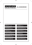
TeleWell TA 128K
TeleWell ISDN TA 128K
Windows 95/98, Me, NT4, 2000, Xp ja Linux
Aktiivinen ISDN-sovitin RS232-porttiin
Versio 6
.
1
TeleWell TA 128K
1
Esittely ............................................................................................................ 3
1.1
Yhteydet Internetiin ....................................................................................... 4
1.2
TeleWell TA 128K bios-päivitykset............................................................... 5
1.3
Tekniset hyväksynnät ja standardit .............................................................. 5
1.4
Toimitussisältö ............................................................................................. 6
1.5
Windows 95/98/Me/2000/Xp ajurien asennus .............................................. 6
1.6
ISDN -kanavien testausohjelma................................................................. 12
2.4
Windows NT 4.0 ajurien asennus .............................................................. 13
2.5
Konfigurointi ja testaus Windows NT 4 ympäristössä ................................ 15
2
Malleja Internet yhteyksistä Windows 95/98/Me/NT4/2000/Xp ..................... 17
2.2
AT komennot.............................................................................................. 26
2.3
ISDN -kutsujen hallinta / access control..................................................... 38
2.4
UUS1 ......................................................................................................... 39
2.6
Multilink PPP protokolla ............................................................................. 41
2.7
Bios-päivitykset .......................................................................................... 42
3
Diagnostiikka ja virheviestit........................................................................... 43
3.1
AT -komentojen virheet .............................................................................. 43
3.2
ISDN virheiden syyt ja selitykset(DSS1) .................................................... 44
3.3
CAPI virheet ja selitykset ........................................................................... 45
4
2
Liitteet ........................................................................................................... 47
A1:
Tekniset tiedot / Technical data: ................................................................ 47
A2:
LED näyttö/display ..................................................................................... 48
A3:
ISDN RJ45 kaapelin signaalit..................................................................... 49
A4:
PRS232 portin signaalit V.24/V.28 / TA 128K (DSUB 9)............................ 49
TeleWell TA 128K
1 Esittely
Tämä ohjekirja on tehty TeleWell ISDN TA 128K mallille
Laitteen asennus on vain suomeksi.
AT –käskykanta on vain englanniksi jotta vältytään alkuperäisten termien
käännös- ja tulkintavirheiltä
a)
TeleWell ISDN TA 128K
Laiteversio V1.0 tai uudempi
Ohjelmistoversio V5.311 tai uudempi
Laitteissa on vakiona uusin bios.
Katso päivitysohje jäljempänä sivulla 42.
b) TeleWell ISDN TA 128K on aktiivinen ISDN -sovitin.
Laite toimii kaikissa tietokoneissa joissa on RS232 –portti, TCP/IP protokolla,
AT-komentoja käyttävä soitto-ohjelma ja Internet selain / sähköpostiohjelma.
c) Laitteessa/ohjelmassa on vakiona CAPI 2.0 protokolla (User mode 32
bittinen). Huomautus ! Capi 2.0 käyttö ei ole pakollista kuin ohjelmille jotka sitä
edellyttävät, esim. PCAnywhere, RVS.
d) Jotta laite saavuttaisi maksimi nopeuden RS232 portissa, niin tietokoneen
UART piirin tulee kyetä 230.000 nopeuteen. TeleWell HK 10 jossa uudempi 16650
UART) toimii ML PPP 128K yhteys noin 8-10k nopeudella jos käytetään tavallista
UART piiriä.
e) Telefaksikäyttöön tarvitset Easytel Oy:stä erikseen ostettavan RVS –
ohjelmiston 1.56 tai mahdollisesti uudempi versio, joka tukee G3-faksitoimintoja Windows 95/98 ja NT 4:ssä.
3
TeleWell TA 128K
TeleWell TA128K ja sen käyttö Internetiin
Huomautus! Laitteen tekninen asennus alkaa sivulta 7
Laiteella käytetään ISDN –internet-yhteyttä seuraavilla protokollilla
:
•
PPP 64k tai Multilink PPP 128k protokollalla (Oletus suomessa).
•
tai V.120 protokollalla
•
tai X.75 protokollalla
G3-telefaksien lähetys ja vastaanotto edellyttää asennusohjelmien suoritusta
ja RVS-ohjelmaa, jonka versio on 1.56 tai mahdollisesti uudempi.
Kytkentätapa
Tietokone/RS232->TA128K RJ45-kaapeli->ISDN NT1–verkkopääte -> Internet operaattori
4
TeleWell TA 128K
1.2 TeleWell TA 128K bios-päivitykset
Uusin flashbios-päivitykset laitteelle haetaan osoitteesta www.easytel.fi tai
CD-ROM levyltä hakemistosta \TA128K.
UPDATE Firmware painikkeella päivität uuden biossin. TA128A, TA128CI ja
TA128+NT1 bios-koodit eivät sovellu TA128K mallille.
1.3 Tekniset hyväksynnät ja standardit
TeleWell TA 128K täyttää eurooppalaiset hyväksynnät CE 0180x , IEC 60 950.
Laitteessa tulee käyttää vain ja ainoastaan verkkovirtalaitetta joka on mukana
paketissa. TeleWell TA 128K laite pitää kytkeä EURO ISDN –standardin
mukaiseen S0 –väylään joka täyttää standardin SELV (Safety Extra Low Voltage)
EN60950.
TeleWell ISDN TA 128K täyttää myös seuraavat eurooppalaiset standardit; EMC.
EN50081-1, ja EN55022 Class B ja EN50082-1
5
TeleWell TA 128K
Laitteen asennus
1.4 Toimitussisältö
•
•
•
•
•
•
Aktiivinen ISDN -sovitin TeleWell ISDN TA 128K
Verkkovirtalaite
ISDN –kaapeli 5 m
Modeemikaapeli RS232
Asennusohjelma Windows 95/98Me ja NT 4/2000/Xp CD:llä
Ohjekirja
1.5 Windows 95/98/Me/2000/Xp ajurien asennus
Jos Windows tunnistaa laitteen itse niin osoita oikea asennushakemisto CD –levyltä
\TA128K. Jos automaattinen tunnistus ei käynnisty niin suorita setupta.exe ohjelma
Asennusohjelma asentaa
•
•
•
Modeemiajurit modeemilistalle ML PPP128K ja PPP 64K
CAPI 2.0 ajuri
Bios-päivitys- ja yhteyden testausohjelma
1.5.1 Asennuksen valmistelu (Windows 95/98/Me/2000/Xp)
Tarkista seuraavat asiat ennen kuin suoritat asennuksen:
•
•
•
•
•
•
•
•
•
6
Kytke TA 128K tietokoneeseen kun virta on sammutettuna tietokoneesta
TA128K sähköverkkovirtajohto kytketään vasta kun Windows on
täysin käynnistynyt.
Koneessa on CD-asema ja kovalevy
Windows 95 a, b, tai c versio tai Windows 98,Windows Me, Windows NT 4 (SP
6a), Windows 2000 tai Xp
TeleWell TA128K asennus CD
Puhelinverkkoyhteydet on asennettuna koneisiin ( Windows asennus)
Vähintään 16 MB keskusmuistia
Internet selain ja muut tarvittavat tietoliikenneohjelmat ovat asennettuina
TeleWell TA 128K
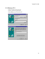
1.5.2 Asennus (Windows 95/98/Me/2000/Xp)
1.
Kytke TA128K sähköverkkoon
Mikäli laitetta ei heti tunnisteta automaattisesti niin mene kohtaan
Ohjainpaneeli;
-Aseta TA128K asennus-CD koneeseen
-Lisää uusi laite
-Valitse seuraava/Next 2 kertaa
-Valitse automaattinen uuden laitteen etsintä
-Kun laite on löytynyt niin osoita sille ajuripolku.
Osoita asennuspolku CD:ltä Setupta.exe asennusohjelma ja sen hakemisto.
Windows 2000, Xp ja Me versiossa ei saa käyttää automaattista hakua
vaan polku pitää määritellä ja tätä toimintoa suositellaan aina.
Jos Windows Me, 2000 tai Xp ilmoittaa että ajuri ei ole Microsoft
tarkistama
niin ohita tiedustelu vastaamalla Y=kyllä.
-Valitse seuraava/next
-Windows tunnistaa uuden laitteen 128K.
Valitse TeleWell TA128K asennusohjelman ensimmäisestä ruudusta Next
-Hyväksy asennushakemistoksi ruudulla näkyvä oletus ja valitse Next
-Hyväksy ohjelmaryhmä ja valitse Next
7
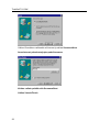
TeleWell TA 128K
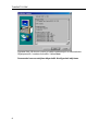
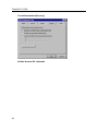
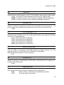
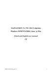
Lopussa näet yllä olevan ruudun ja kaikki modeemiajurit on asennettuina
Ohjainpaneelin / modeemit alueella. Valitse Next
Seuraavaksi asennusohjelma käynnistää Konfigurointi-ohjelman.
8
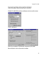
TeleWell TA 128K
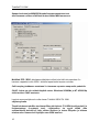
Konfigurointi
Euroopassa käytetään DSS1 protokollaa joka on oletus.
Update firmware –painikkeella voidaan kohdassa päivittää laitteen flashbiosohjelmisto.
9
TeleWell TA 128K
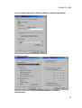
Saapuvien kutsujen MSN/ISDN-puhelinnumeroasetukset teet
alla olevassa ruudussa Sallitaan kutsut tähän MSN numeroon.
Multilink PPP / BOD -kohdassa määrittelet milloin laite lisää tai vapauttaa 2:n
kanavan vapaaksi muille ISDN –laitteille kapasiteetin tarpeen mukaan.
Call bumping kohdassa asetetaan 2:n kanavan vapautus saapuvalle puhelulle.
CHAP –kohta on vain erikoiskäyttöä varten. Windows 95/98/Me ja NT 4/2000/Xp
eivät tarvitse CHAP asetusta.
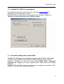
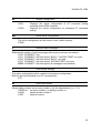
Lopuksi asennusohjelma luo alla olevan TeleWell ISDN TA 128K
ohjelmaryhmän.
Tässä kohdassa tehdään tarvittavat Bios-päivitykset (TA ISDN konfigurointi) ja
linjatestaukset (Loopback test). Linjatestaus on syytä tehdä aina
ensimmäisellä kerralla eli laite soittaa itselleen ja testaa liittymän ja laitteen
toimivuuden. Numeroksi käyttäjän oma ISDN numero.
10
TeleWell TA 128K
Kun tämä kaikki on tehty niin ohjelma pyytää koneen uudelleen käynnistystä.
1.5.3 Asennuksen purku / Deinstallation
Tällä ohjelmalla poistat onnistuneesti suoritetun asennuksen.
11
TeleWell TA 128K
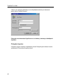
1.6 ISDN -kanavien testausohjelma
Anna oma ISDN –puhelinnumero (molemmat linjat pitää olla vapaana) eli se numero
josta soitat ulos.
Valitse Start Test
Lopussa ilmoitus testin onnistumisesta
Poistu testiohjelmasta ruudun oikean yläkulman X –painikkeen kautta.
12
TeleWell TA 128K
2.4
Windows NT 4.0 ajurien asennus
Tarkista seuraavat asiat ennen kuin suoritat asennuksen:
•
•
•
•
•
•
•
•
Kytke TA 128K tietokoneeseen kun virta on sammutettuna tietokoneesta
Koneessa on CD levykeasema ja kovalevy
Windows NT 4 (SP 6a)
Puhelinverkkoyhteydet & etäkäyttöpalvelu on asennettuina Windowsiin
Vähintään 64 MB keskusmuistia
Asennus CD TA 128K
Internet selain ja muut tarvittavat tietoliikenneohjelmat ovat asennettuina
TA128K sähköverkkovirtajohto kytketään vasta kun Windows on
täysin käynnistynyt.
Seuraavat ohjelmistot asennetaan:
•
•
•
Modeemiajurit modeemit listalle
CAPI 2.0 ajuri
Konfigurointiohjelma
2.4.1 Asennus
1.
Käynnistä SETUPTA.EXE –ohjelma asennus CD:tä \Finnish tai \English
hakemistoista riippuen siitä minkä kielisen version haluat.
2.
Seuraa ruutuohjeita ja etene Next valinnoilla. Käytä ohjelman
oletusasetuksia
Asennusohjelma etenee aivan samoin kuin Windows 95/98 asennuksessa,
josta voit seurata tarkemmat valinnat.
Lopuksi ohjelma ehdottaa koneen ja Windows NT 4:n uudelleen
käynnistystä. Tee se, jos muita sovelluksia ei ole avoinna.
Laitetta ei voi käyttää ennen kuin Windows on käynnistetty uudelleen.
Windows NT 4 .n uusia modeemiajureita ei voi käyttää ennen kuin NT 4 on
käynnistetty uudelleen.
Käynnistä kone
Modeemien lisäys Modeemit listalle ja RAS/Etäkäyttöpalvelun asetukset
Internet käyttöön.
3.
4.
5.
6.
7.
8.
13
TeleWell TA 128K
9.
Modeemin lisäys
Käynnistä/Start -> Asetukset/Settings -> Ohjainpaneeli/ Control Panel >Modeemit/Modems
Valitse
-Lisää / Select ADD ja aktivoi valinta
“Älä tunnista automaattisesti” /
"Don´t detect my modem, I will select it from a list".
Valitse
-Anna Levy / Have a DISK ja valitse poluksi TA 128K asennus CD \Finnish
jossa sijaitsee " mdmtwta.inf" -tiedosto.
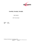
Valitse listalta haluttu ajuri:
Windows NT 4 käyttää RAS / etäkäyttöpalvelussa vain 1:tä ajuria kerrallaan,
joten ajuriksi suositellaan TA 128K-ajuria eli 128K nopeus,
ja Modeemin ominaisuuksissa -kohdassa lisäasetukset voi vaihdella
nopeusasetusta: ATB3 on 64K ja ATB31 on 128K.
TA 128K HDLC
TA 128K ML-PPP Suositus
TA 128K T.70-BTX
TA 128K V.120
TA 128K X.75
Jos NT 4 Ras haluaa lisätä modeemin RAS/etäkäyttöpalveluun, niin
suorita lisäys ja tarkista jäljempänä olevasta Windows NT 4 ja Internet
-mallista oikeat asetukset.
14
TeleWell TA 128K
2.5
Konfigurointi ja testaus Windows NT 4 ympäristössä
Toiminto on sama kuin Windows 95/98/Me/2000/Xp –versiossa.
Katso ohjeistus Windows 95/98/Me/2000/Xp alueelta.
2.55 LINUX ajurien asennus
Linux ympäristössä käytetään Hayes-yhteensopivaa modeemiajuria ja haluttuja AT –
komentoja ohjekirjasta.
Perusasetus Linuxille
AT&F&K3B3
Tehdasasetus, RTS/CTS päälle/ 64K nopeus
B31 mahdollistaa 128K nopeuden
128K nopeudella TCP/IP header compression on oltava OFF –
tilassa
15
TeleWell TA 128K
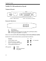
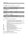
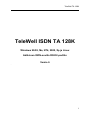
TeleWell TA 128K merkkivalot ja liitynnät
Takapaneeli/liitynnät
DTE
ISDN
PWR
Virtaliitin ISDN RJ45 liitin
RS232 –TIETOKONETTA VARTEN
Etupaneeli / Merkkivalot
L1
B1
R
DCD
L2
B2
T
DTR
T:
Tiedonlähetys
R:
Tiedonvastaanotto
DTR : Tietokone on kytkeytyneenä TA 128K malliin (päällä/pois päältä)
DCD : DCD signaali (linja päällä / pois päältä).
Molemmat merkkivalot B1 ja B2, kertovat linjojen toiminnasta (päällä/pois päältä)
Merkkivalot L1 ja L2, ilmoittavat laitteen yleisestä tilasta kooditasolla.
Toiminto
1.
Virran kytkentä, odota
2.
Aktiivinen tila Layer 1 päällä
Layer 1 voi olla myös OFF tilassa
3.
Yhteys päällä etäkohteeseen
LED symbolit:
16
⊗
Θ
O
Päällä
Vilkkuva merkkivalo
Pois päältä
L1
L2
⊗
⊗
O
⊗
Θ
O
O
⊗
(n 2 sekuntia)
TeleWell TA 128K
2 Malleja Internet yhteyksistä
Windows 95/98/Me/NT4/2000/Xp
Tähän osaan on kerätty kuvaesitys asetuksista jotka pitää olla Windows 95/98Me ja
NT 4/2000/Xp –ympäristössä, jotta yhteydet toimivat moitteetta.
2.1.1 Windows 95/98/Me/2000/Xp
Valitse Puhelinverkkoyhteydet
Lisää uusi palvelu
Valitse kohteeksi ”Internet” jos Windows esittää kysymyksen palvelun
kohteesta.
Valitse manuaalinen asennus jos asennus ehdottaa Internet
yhteyden automaattista asetusta (Verkko Æ modeemin kautta).
Käytä oman Internet palvelusi tietoja asennuksessa.
Anna palvelulle nimi ja valitse modeemiajuri
ML PPP 128K yhteyksiä varten ja 128K PPP 64 yhteyksiä varten
17
TeleWell TA 128K
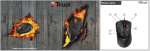
Tarkista laitteen määrityksistä että asetukset vastaavat oheista kuvaketta
Valitse Seuraava
Anna Internet yhteyden puhelinnumero
Maavalinta tulee olla Finland
Suuntanumero tarvitaan, mikäli numero ei ole paikallinen tai valtakunnallinen
numero.
Valitse Seuraava ja Valmis
Nyt yhteytesi on tehty, mutta seuraavat kohdat pitää vielä tarkistaa
18
TeleWell TA 128K
Perusoletukset yhteydelle (Soittokuvakkeen ominaisuudet kohta)
TCP/IP asetukset
Lopussa kuittaa valinnat OK ja yhteyskuvakkeesi on valmis
Yhteydenotto
19
TeleWell TA 128K
Valitse uusi yhteyskuvakkeesi ja anna käyttäjätunnuksesi ja salasanasi
sekä valitse Yhdistä/Connect
Yhteyden muodostuttua käytä Internet -selainta ja haluttuja sähköpostiohjelmia.
Yhteyden lopetus
Yhteyden lopetus tapahtuu alapalkissa olevan Datayhteyskuvakkeen kautta
valitsemalla ”Disconnect/Lopeta yhteys”
20
TeleWell TA 128K
2.1.2 Windows NT 4
Valitse Puhelinverkkoyhteydet
Valitse Uusi ja anna Palvelulle nimi
21
TeleWell TA 128K
Valitse Ylimmäinen vaihtoehto eli Internet ja valitse Seuraava/Next
Anna Internet palveluntarjoajan puhelinnumero
Kuittaa valinta painikkeella Seuraava/Next
Valitse Valmis/Finish
22
TeleWell TA 128K
Seuraavaksi tee Soittokuvakkeen lopulliset määritykset
Valitse Muuta/More /Muuta asetuksia (ylin vaihtoehto)
TeleWell TA 128K ISDN-sovittimen määritykset oheisen mallin mukaan
TCP/IP -määritykset
PPP/LCP pois päältä ja TCP/IP Header compression pois päältä
Muut määritykset Internet-Operaattorin mukaan
23
TeleWell TA 128K
Turvallisuusasetus(Security)
Kuittaa Asetus OK valinnalla
24
TeleWell TA 128K
Windows 95/98/Me/NT4/2000/Xp nopeuden asetus 64K tai
128K nopeus ja oman ISDN / MSN numeron asetus
Laite näyttää aina nopeusilmoituksen Connect 64000 (ensimmäinen kanava).
Merkkivaloista saat tarkemman tiedon jos käytät ML PPP ajuria.
Mikäli et halua käyttää 128K nopeutta eli 2:n kanavan yhteyttä niin
seuraavassa kohdassa muutat asetusta.
Ohjainpaneeli/modeemit/TA128K ominaisuudet/yhteys/lisäasetukset
ATB31 128K yhteys
ATB3
64K yhteys
Oma ISDN / MSN numeron asetus
Anna hyperterminaaliohjelmassa komento
AT#Z=nn
nn=NUMERO
AT&W
Numero tallentuu automaattisesti muistiin.
25
TeleWell TA 128K
2.2 AT komennot
Käsikirjan loppuosuus on vain englanniksi koska sitä tarvitaan vain
erikoiskäyttöön ja ammattilaisten lisäohjeistukseksi.
With the exception of the command A/ (Repeat command) all commands begin with
the prefix AT and are terminated with <↵>. Corrections in a command line are done
with <BACKSPACE>. A command line has a maximum of 80 characters. The
command line is automatically cancelled by longer input. Blanks are ignored,
capital/small letters are not significant.
The parameter settings of the TA 128K obtained when using the AT commands can
be permanently stored (AT&W) and are not lost by resetting or by leaving the AT
command mode.
To enter the AT command mode during an active data connection you must use the
following sequence ("Escape sequence"):
at least 1 sec pause <+><+><+> 1 sec pause
The time gap between all three plus signs may not exceed 1 sec.
The escape sequence is transmitted transparent to the remote device.
Tuetut komennot:
A/
Repeat last command line
This command repeats the commands of the last entered command line.
Note: No prefix AT is required.
A/
A
Accept incoming call
Using this command you can accept an incoming call, if automatic call acceptance is
not set (Register S0 = 0). An incoming call is displayed by the message “RING“ or
the code “2“.
Must be the last command in an AT command line.
ATA[//<UUS1data>]
UUS1data
transmitted data with UUS1 signalling
B
26
B channel protocol
TeleWell TA 128K
Transmission protocol for data communication in the B channel.
ATB0 : V.110 asynchronous
(i.e. for BBS access)
ATB3 : 64K(PPP asynchronous, single link PPP, default)
(i.e. for Internet / dial-up network access)
ATB4 : HDLC transparent (octets are packed into HDLC frames)
ATB5 : Byte transparent (raw B channel data)
ATB10 : X.75-NL
(i.e. for BBS access)
ATB13 : V.120
(for AOL/CompuServe access)
ATB20 : X.31 B channel (X.25 B channel, option)
ATB21 : X.31 D channel (Option)
ATB22 : T.70-NL-CEPT
(for T-Online (videotex) access)
ATB23 : T.90-NL
ATB31 : Multilink PPP (ML-PPP)
%B
Set local baudrate
Sets the local baudrate of the TA to the desired value (fix value) or to autodetection.
When autodetection is set, the TA will recognize the desired baudrate with every
newly entered AT command by the terminal equipment (PC). With all other settings
the PC must use the same baudrate.
Must be the last command in an AT command line.
AT%B0
Automatic local baudrate detection enabled (autobauding,
default)
AT%B1
Local baudrate set to 1200 bit/s
AT%B2
Local baudrate set to 2400 bit/s
AT%B3
Local baudrate set to 4800 bit/s
AT%B4
Local baudrate set to 9600 bit/s
AT%B5
Local baudrate set to 19200 bit/s
AT%B6
Local baudrate set to 38400 bit/s
AT%B7
Local baudrate set to 57600 bit/s
AT%B8
Local baudrate set to 115200 bit/s
AT%B9
Local baudrate set to 230400 bit/s
27
TeleWell TA 128K
CONF
Enter TA+Configurator
Enters directly into the TA+Configurator, the configuration prompt "#" will be
displayed. Leave the TA+Configurator with the command "quit".
ATCONF
&C
DCD control
Selects the behavior of the DCD control line from the TA 128K.
AT&C
TA 128K control line DCD is always ON
AT&C1
DCD ON indicates ISDN connection is established and
synchronized (default)
#C
Received bearer service
Shows the bearer service that is received with an incoming call in hexadecimal
coding hbhb.
The value for hbhb (word) is the CIP value as defined in the CAPI 2.0 specification.
AT#C
#C1=hbhb
Select bearer service outgoing
Selects the bearer service that will be sent with an outgoing call
The value for hbhb (word) is the CIP value as defined in the CAPI 2.0 specification.
Example: an outgoing call as a voice call: AT#C1=0004.
#C2=hbhbhbhb
Select bearer service incoming
Selects the bearer services that can be accepted with an incoming call. The
definition of hbhbhbhb (double word) is the CIP mask as defined in the CAPI 2.0
specification.
Example:
AT#C2=00030012 : Accept analogue incoming calls
AT#C2=00000001 : Accept all incoming calls.
Note: Before issuing an outgoing call the command AT#C1 has to be set.
To use the predefined services please setup factory defaults (AT&F).
28
TeleWell TA 128K
D
Initiate outgoing call
Dials the number (D for Dial). The dial modifier "W", ">", "T", ";", "@" can be freely
inserted in the dial string; they have no influence on the dial procedure of the TA
128K.
Must be the last command in AT command line.
Any character input while the TA is dialing will cancel the dialing procedure.
ATD<CALLEDnumber>[/<subaddr>][//<UUS1data>]
[,X[Pxxx-][R ][N<nuipwd> ][G<cug> ]<X25number>][D<userdata>]]
CALLEDnumber: ISDN call number for a dialled B channel connection or
X.25 number for X.31 D channel
subaddr
dialled subaddress
UUS1data
transmitted data with UUS1 signalling
P:
use packetsize xxx for X.25 connection
R:
request the facility reverse charging
G:
access to X.25 closed user group
O:
Outgoing call from X.25 closed user group
N:
use NUI and password with call setup
allowed chars: a-z, A-Z, 0-9.
(overrides setting of nui configuration command)
X25number: dialled X.25 call number (X.25 B channel only)
D:
separator for userdata: "D" or ",": user data without
protocol ID "P": user data with protocol ID (“01000000“)
ATDL
ATDS=n
Notes: -
&D
Dial the last dialled number
Dial number n from stored telephone number list (n = 1..3)
(See command AT&Z to store numbers)
To setup the own subaddress see configuration command sub.
Adding an "e" to CALLEDnumber indicates that a connection to the
internal remote access of a TA 128K shall be performed, the protocol
X.75 (ATB10) has to be used.
DTR control
Selects the behavior of the TA 128K, when the DTE control line DTR changes from
ON to OFF.
AT&D
DTE control line DTR setting is ignored
AT&D2
DTE control line DTR is evaluated: dropping the DTR line by the
DTE will disconnect an existing ISDN connection (default).
An incoming call will accepted only with DTR active.
29
TeleWell TA 128K
E
Local echo
Selects the local echo in command mode.
ATE
No local echo
ATE1
Local echo on in command phase (default)
&F
Load factory defaults
Factory default will be loaded, ISDN protocol setting and msn´s will not be
overwritten. (for storing in non volatile memory please use the command AT&W).
AT&F
setup all parameter concerning data port
AT&F1
setup all parameter including ISDN protocol and msn settings.
H
Disconnect
Disconnects existing ISDN data connection, after issuing the Escape sequence (see
page 26).
ATH[//<UUS1data>]
UUS1data
transmitted data with UUS1 signalling
#H
Display msn
Shows own msn (multiple subscriber number) for the data port.
default: msn = "*" (no msn).
The msn can be set by command AT#Z.
AT#H
I
Display version information
Displays different information about version number and settings:
ATI Returns the "Modem"-type; name of the terminal adapter (“TA 128K“)
ATI1 Returns internal checksum (“64“)
ATI2 Returns “OK“
ATI3 Returns version string: "TA5.xy.z0"
ATI4 Returns manufacturers name: "TeleWell TA 128K “
ATI5 Returns ISDN selected protocol: "0 - DSS1"
ATI6 Returns copyright string: "(c) Copyright Easytel Oy"
ATI9 Returns plug and play ID string
ATI99 Returns software creation date
30
TeleWell TA 128K
&K
Flowcontrol
Selects the flow control behavior of the TA 128K while in data communication phase.
AT&K No local flow control between the DTE and TA 128K is used
AT&K3 Local flow control is set to hardware handshake RTS/CTS (default)
AT&K4 Local flow control is set to software handshake XON/XOFF
#M
Received CLID
Shows the called line identification (CLID) that is received with an incoming call – this
is the number of the called party addressed on the local S-bus (selected msn).
AT#M
N
Set line baudrate V.110
Selects the line baudrate of the TA to the desired value (only valid for B channel
protocol V.110 asynchronous).
ATN1 Line baudrate set to 1200 bit/s
ATN2 Line baudrate set to 2400 bit/s
ATN3 Line baudrate set to 4800 bit/s
ATN4 Line baudrate set to 9600 bit/s
ATN5 Line baudrate set to 19200 bit/s
O
Return to online state
If the TA 128K is in command mode after issuing an escape sequence out of an
existing connection, ATO brings the TA 128K back to data phase.
Must be the last command in AT command line.
ATO
#O
Received CLIP
Shows the calling line identification (CLIP) that is received with an incoming call –
number of the calling party.
AT#O
Q
Suppress results
With this command result codes or messages can be suppressed.
ATQ
Returns status - codes after command input (default)
ATQ1
No result codes are returned
31
TeleWell TA 128K
&R
CTS control
Selects the behavior of the CTS control line from the TA 128K.
AT&R
TA 128K control line CTS is following all changes of RTS
AT&R1
CTS is always ON (default)
#R
Handle incoming calls
Selects the behavior of the TA 128K when an incoming call is received.
AT#R
Disable automatic reject of all incoming calls (default)
AT#R1
Enable automatic reject of all incoming calls
S
Display and set internal S register
ATSnn?
ATSnn=xx
&S
Show actual values (decimal) of selected register nn
Set selected register nn to the decimal value xx.
DSR control
Selects the behavior of the DSR control line from the TA 128K.
AT&S
TA 128K control line DSR is always ON (default)
AT&S1
DSR ON indicates ISDN connection is established and
synchronized
V
Result format
ATV
ATV1
ATV2
ATV3
32
Result is presented as numbers (followed by <↵>)
Result is presented as text (default)
Result is presented as text
RING and CONNECT including ISDN address, all others include
error causes
Result is presented as numeric codes
RING and CONNECT including error causes and ISDN address,
all others include error causes
TeleWell TA 128K
&V
Display configuration
AT&V
AT&V1
&W
Displays the actual configuration of AT command setting
including stored ISDN numbers
Displays the actual configuration of extended AT command
setting
Store active configuration
The active configuration will be stored in non volatile memory.
AT&W
X
Reduce result messages
Reduces the number of result messages after trying to set up a connection
ATX0 "CONNECT" only
ATX1 "CONNECT" with line speed, "BUSY", "NO DIALTONE" not used
ATX2 "CONNECT" with line speed, "BUSY" not used
ATX3 "CONNECT" with line speed, "NO DIALTONE" not used
ATX4 "CONNECT" with line speed, all messages used (default).
Z
Load stored settings
The active configuration will be resetted to the stored configuration.
Must be the last command in an AT command line.
ATZ
&Z
Store call-number
Stores dialing number nn as entry number x into the telephone list (x = 1..3).
AT&Zx=nn set entry number x to dialling number nn
AT&Zx
shows entries number x.
AT&Z
show all entries.
33
TeleWell TA 128K
#Z
Define own msn
Defines the msn nn for the data port.
If the number is set to “*“ (default), all incoming calls are acceptable.
The msn can be displayed by command AT#H or AT&V.
AT#Z=nn
The msn is automatically stored to non volatile ram.
**DBITS
Number of data bits x asynchronous chars (7,8)
Number of data bits x for asynchronous character (7,default: 8)
AT**DBITS=x
**PRTY
Set Layer 2 windowsize
Selects the parity for asynchronous characters.
0: no parity; 1: even parity; 2: odd parity
AT**PRTY=0
No parity (default)
AT**PRTY=1
Even parity
AT**PRTY=2
Odd parity
34
TeleWell TA 128K
2.2.1 ISDN specific AT commands
Setting up special ISDN parameter:
(only one command is allowed per AT command)
**BSIZE
Set B channel blocksize
Defines the maximum length x of a data block transmitted or received in B channel
(default: BSIZE = 2048).
AT**BSIZE=x
Note:
The value will be changed by setting the B channel protocol (ATBx).
**LLC
Set low layer compatibility (LLC)
Defines the LLC value for outgoing calls in hexadecimal format. In some situation a
specific LLC value is required to pass detailed information about the used B channel
protocol to the called party. This can be done by setting the LLC to a fix value.
An empty parameter has to be entered by "-" (default: LLC is empty).
Example:
Deleting of LLC-value:
AT**LLC=-<↵>
Entering a new LLC:
AT**LLC=8890<↵>
Note: The value will be changed by setting the B channel protocol (ATBx).
**DTE
Set B channel Layer 2 address
Selects the Layer 2 link addresses. Only valid for protocols that are HDLC based
(X.75, LAPB).
AT**DTE=0 Calling side reacts as DTE,
called side reacts as DCE (default, X.75 standard)
AT**DTE=1 TA reacts as DTE (own adr = 01)
AT**DTE=3 TA reacts as DCE (own adr = 03)
Note: The value will be changed by setting the B channel protocol (ATBx).
**ISDN
Select D channel protocol
Selects ISDN D channel protocol to the ISDN line. The protocol must fit the protocol
running on the ISDN line otherwise a connection cannot be set up.
Note: after changing and storing the ISDN protocol the TA has to be resetted by
powering it off and on.
AT**ISDN=0
Select DSS1 (Euro-ISDN)
(default)
AT**ISDN
Show selected ISDN protocol
AT**?ISDN
Show available ISDN protocols
**K
Set Layer 2 windowsize
35
TeleWell TA 128K
Sets windowsize x layer 2 protocol B channel: x = 1 ..7, default: 7
AT**k=x
The default value is dependent of the selected B channel protocol.
**RPWD
Password remote configuration
Sets password for remote configuration to nn (1..32 chars)
AT**RPWD=nn
Default: empty.
**SPID1, SPID2
Set SPID
(Option)
For ISDN lines in the U.S. you have to set the SPID. You get it from your ISDN
provider.
AT**SPID1=xxxx Set SPID 1
AT**SPID2=xxxx Set SPID 2
**<cmd>
Execute configuration command
Executes one configuration command, for definition of commands see page
AT**<cmd>
2.2.2 AT kommenot ja S rekisterien asetukset
S0
S1
S2
S3
S4
S5
S7
S9
S16
S90
S91
0: No automatic call acceptance, acceptance of an incoming call is
controlled by the data terminal (command ATA after RING)
1: Immediate call acceptance by the terminal adapter (default)
2..n: Call acceptance through the terminal adapter after n "RING"
messages.
Note: The time between two ring messages can be configured using
the TA-configuration command “ringtimer“ (default = 5 sec.)
Ring Counter (read only)
Escape Character (default = 43h)
Carriage Return Character (default = 0Dh)
Line Feed Character (default = 0Ah)
Backspace Character (default = 1Ah)
Wait time for Carrier (sec) (default = 30 sec)
Enable PNP functionality for Windows95 (default=1, enabled)
Last occurred CAPI/ISDN error cause
Last incoming ISDN calling number (CLIP)
0: default
1: all unknown AT commands will be answered with OK.
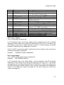
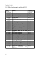
2.2.3 AT vastekoodit/result codes
Vaste koodit/ Result codes (numerical and verbose):
36
TeleWell TA 128K
Code
0
1
Text
OK
CONNECT <rn>
2
3
4
RING <rn>
NO CARRIER <xx>
ERROR
5
6
7
8
CONNECT 1200 <rn>
NO DIALTONE <xx>
BUSY <xx>
NO ANSWER <xx>
10
11
12
16
19
CONNECT 2400 <rn>
CONNECT 4800 <rn>
CONNECT 9600 <rn>
CONNECT 19200 <rn>
CONNECT 64000 <rn>
Meaning
Command completed
Connection established
(rn = call number of remote site)
Indicates an incoming call (SETUP received)
No synchronization (xx = ISDN error cause)
Illegal command or error that can not be
indicated otherwise
Connection, line speed 1.2 kbps (V.110)
No access to ISDN network (xx = ISDN error)
Number engaged (xx = ISDN error cause)
No connection; called number can not be
reached (xx = ISDN error cause)
Connection, line speed 2.4 kbps (V.110)
Connection, line speed 4.8 kbps (V.110)
Connection, line speed 9.6 kbps (V.110)
Connection, line speed 19.2 kbps (V.110)
Connection, line speed 64 kbps
Call number display:
<rn> = call number of remote site
In AT command mode, call number display (does not belong to the AT command
standard) can be turned on by issuing the command ATV2 or ATV3. If turned on, the
call number of the caller is shown with the Connect- or Ring-message (in pointed
brackets), depending on the signaling in D-channel.
If the TA 128K is used at the public network then the call number of the remote site
(including area code) is displayed.
Example:
CONNECT 64000 <040890880>
Error cause display:
<xx> = ISDN release (error) cause, hexadecimal
Example:
NO CARRIER <#34F0>
In AT command mode, error cause display (does not belong to the AT command
standard) can be turned on by issuing the command ATV2 or ATV3. The shown
error causes use the coding defined by the CAPI definition. ISDN error causes from
the ISDN network are always coded as 34xxH, where xx represents the hexadecimal
version of the ISDN error cause (see page 44). All other causes are CAPI error
causes (see page 45).
37
TeleWell TA 128K
2.3 ISDN -kutsujen hallinta / access control
Using these commands you can setup a table, to allow only dedicated callers to get
a connection to the TA. If this list is empty (default) or one entry is set to star (*), any
incoming call is allowed. Every incoming call that does not fit to one of the entries of
acctab will be ignored. The received calling party number is compared to every entry
beginning at the last digit and is stopped when the shorter number is completely
compared.
acctabx nn/ss set entry number x to ISDN number nn and subaddress ss
acctabx clear entry number x
acctabx *
Allow all incoming calls to be accepted
acctabx
show entry number x
acctab
Show all entries
Maximum number of entries = 5; x = 1..5
Maximum length of ISDN number = 20 digits
Maximum length of subaddress = 20 digits
The ISDN number nn can contain wildcards:
* : represents one or more digits
? : represents exactly one digit
Note: If a subaddress is set, the received calling subaddress must be identical to the
subaddress that is set.
Examples:
acctab1 1234567890
acctab2 *456*
acctab3 ?2345678??
acctab2 *1234/987
acctab3 *
acctab3 -
accept only specified number
accept all numbers with 456 somewhere in the
middle
accept all number with 2345678 in the middle
peceeded by one digit and followed by two digits.
accept all numbers that end with 1234 and have
the subaddress 987
accept all incoming calls without subaddress
clear entry no. 3
Note:
If you are not sure, in which format the calling number will be presented with
an incoming call, please use the command ATV2 to see the the format of the
calling number in the RING message. This number can be entered into the
acctab.
38
TeleWell TA 128K
2.4 User to User Signalling UUS1
With outgoing and incoming calls the transmission of User-to-User-Data (UUS1data) can be performed using the ISDN supplementary service UUS1. The UUS1data are transmitted transparently from the calling party to the called party before the
B channel connection is fully established.
Please note, that this ISDN service typically has to be enabled by the ISDN service
provider and may be charged additionally.
See the command ATD in AT command set:
Example:
ATDisdnnumber[//<UUS1-data>]
(PAD:)
X25number[I<ISDNnumber>[//<UUS1data>]]
“//”: separator for UUS1-data
The UUS1-data have a maximum length of 128 Bytes and will be interpreted as
ASCII characters.
Incoming UUS1-data are presented as enhencement to the RING and CONNECT
message.
AT:
RING [<rn>] [//<UUS1-data>]
CONNECT [<rn>] [//<UUS1-data>]
PAD: <X.25addr>I<isdnnumber>[//<UUS1-data>]
COM
Note: The presentation of UUS1-data has to be enabled by command ATW1.
The data are presented as ASCII characters.
An incoming call can be accepted (S0 register set to 0) by an ATA or rejected by an
ATH combined with the transmission of UUS1-data (AT only):
ATA [//<UUS1-data>]
ATH [//<UUS1-data>]
Examples:
ATD1234567890//userdata#010203*ende
RING //userdata
RING //#01020304
39
TeleWell TA 128K
2.5 Alanumerot / Subaddressing
With outgoing and incoming calls the transmission of subaddresses can be
performed using the ISDN supplementary service SUB. The subaddress is
transmitted transparently from the calling party to the called party before the B
channel connection is fully established.
Please note, that this ISDN service typically has to be enabled by the ISDN service
provider and may be charged additionally.
The subaddress is separated by an “/“ from the called number.
The functionality Subaddressing can be used with the dialling procedures ATcommand set, PAD X.3 and automatic call.
Examples:
ATDisdnnumber[/subaddr]
isdnnumber
Dialling called party number
subaddr
Called subaddress
RING [<rn>[/subaddr]]
CONNECT [<rn>[/subaddr]]
rn
subaddr
Calling party number
Calling party subaddress
The own subaddress (calling subbaddress) can be setup using the configuration
command sub.
Note: The subaddress can be entered additionally into all tables that contain ISDN
numbers for dialling or checking an ISDN address.
40
TeleWell TA 128K
2.6 Multilink PPP protokolla
This chapter is not needed for normal Internet connections
To enable Multilink PPP handling within the TA please enable the B channel protocol
ML-PPP: atb31 rsp. prot = 31.
ML-PPP may be used with different authentification procedures during the call up of
the line. One of these is CHAP. You may enable ML-PPP CHAP by the following
steps:
• Type “at**chappwd=<password>” to input your password in the TA.
• Type “AT&W” to store the setting in the TA.
Afterwards a ML-PPP connection is initially made using CHAP authentification. If the
server does not handle CHAP an automatic fallback to PAP is performed.
You may control the settings by typing “AT&V1”.
Warning: Since the password is shown in plain text it may be disclosed by
unauthorized persons.
2.6.1 Dynaaminen kanavan vapautus / Call Bumping
This setting is done by configuration programs during Windows installation.
A ML-PPP connection uses both B-channels of the S0 bus. To accept an incoming
call (i.e. for telephony) during a ML-PPP session one B-channel has to be released.
This is called Call Bumping.
To enable Call Bumping proceed as follows:
• Activate call waiting on the S0 bus. It has to be activated in the ISDN switch and
is a feature of the ISDN line you ordered.
• Open the “properties” of the dial-up link you are using for ML-PPP and “additional
settings”. Input “at**cmlp=1” as an additional parameter.
If there is an incoming call during a ML-PPP session the TA will drop one B-channel
and an ISDN telephone attached to the S0-bus will be ringing to accept the call.
41
TeleWell TA 128K
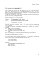
2.7 Bios-päivitykset / Software update
The TA 128K uses a Flash-EPROM for software updates to store the operational
software. This software can be updated from a local connected PC via the COM port
or via an remote configuration connection.
2.7.1 Bios-päivitys Hyperterminaaliohjelmalla
Please fulfil the following steps to update the TA 128K locally:
•
•
•
•
•
•
•
•
Get a new software release for the TA 128K from your supplier and copy it to
your PC.
Start a terminal emulation on your PC with the capability to run an X-MODEM file
transfer (i.e. HyperTerminal).
Enter the AT command “at**fwload“.
Wait for end of erasing the Flash-EPROM and the prompt to start your XMODEM transfer.
Start the 1kX-MODEM file transfer (send file or upload) by selecting the Transfer /
Send File menu point in your terminalemulation and select the new software.
After completion you will get the information whether the software update ended
successfully or erroneous.
Give the TA 128K about 20 seconds to activate the new software.
Due to new functionality the last stored configuration setting may be lost, please
check before using. To set factory default values please use the command
"at&f1".
Note:
Due to an error it may be that no firmware is active within the TA. This will be
indicated by flashing of the LEDs L1, L2, B1, B2 (Bootloader active). To store
a new firmware correctly you have to enter the command at**flash and load a
firmware using the XMODEM protocol as described above.
42
TeleWell TA 128K
3 Diagnostiikka ja virheviestit
For the diagnostic of erroneous situations the following functionality is supported.
Please check first the behaviour of LED displays, if an ISDN connection can not be
established. Refer to list of LED displays on page 48.
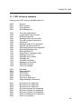
3.1 AT -komentojen virheet
When the extended result messages are selected using the command ATV2 ISDN
error codes are displayed in addition to the standard AT result messages.
ISDN error causes from the ISDN network are always coded as 34xxH, whereas the
last two digits xx represent the ISDN cause in hexadecimal coding. The meaning can
be taken from the following tables ISDN causes (see page 44).
43
TeleWell TA 128K
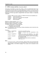
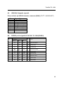
3.2 ISDN virheiden syyt ja selitykset(DSS1)
Cause
Decimal /
Hexadecimal
1 / 0x81
3 / 0x83
6 / 0x86
16 / 0x90
17 / 0x91
18 / 0x92
19 / 0x93
21 / 0x95
22 / 0x96
26 / 0x9A
27 / 0x9B
28 / 0x9C
29 / 0x9D
31 / 0x9F
34 / 0xA2
38 / 0xA6
41 / 0xA9
42 / 0xAA
47 / 0xAF
50 / 0xB2
57 / 0xB9
58 / 0xBA
63 / 0xBF
65 / 0xC1
70 / 0xC6
79 / 0xCF
87 / 0xD7
88 / 0xD8
111 / 0xEF
127 / 0xFF
44
Meaning
Translation to
X.25 cause +
diagnostic
Unassigned number
No route to destination
Channel unacceptable
Normal clearing
User busy
No user responding (i. e. DTR not
ON)
Call rejected
Number changed
Non selected user clearing
Destination out of service
invalid number format
Facility rejected
Normal disconnect, unspecified
No B channel available
ISDN network out of order
Temporarily failure of the ISDN
network
ISDN network congestion
ISDN network congestion
Requested facility not subscribed
Bearer capability not authorized
Bearer capability not available
Service/option not available
Bearer capability not implemented
Only
restricted
digital
bearer
capability (BC) available
Service/option not implemented
User not member of CUG
Incompatible destination
Protocol error, unspecified
Network
interworking
error,
unspecified
13, 00
0D, 00
05, 00
00, 00
01, 00
09, 00
21, 00
0D, 00
00, 00
09, 00
13, 00
13, 00
00, 00
01, 00
05, 00
05, 00
05, 00
05, 00
13, 00
13, 00
13, 00
13, 00
13, 00
13, 00
13, 00
21, 00
21, 00
05, 00
05, 00
TeleWell TA 128K
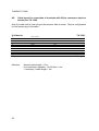
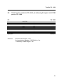
3.3 CAPI virheet ja selitykset
Coding of the CAPI cause in hexadecimal form.
0000
0001
0002
0003
No error
NCPI ignored
Flags ignored
Alert already sent
1001
1002
1003
1004
1005
1006
1007
1008
100a
100b
1101
1102
1103
1104
1105
1106
1107
1108
1109
Too many applications
Logical block size too small
Buffer exceeds 64k
Message buffer size too small
Too many logical connections
Reserved1
Message could not be accepted
Register OS Resource Error
External Equipment not supported
External Equipment only
Bad application ID
Illegal cmd or message length
Message queue full
Message queue empty
Message lost
Unknown notification
Message not accepted
OS Resource Error
CAPI not installed
2001
2002
2003
2004
2005
2006
2007
Bad State
Illegal Identifier
Out of PLCI
Out of NCCI
Out of LISTEN
Out of Fax Resources
Illegal Message Parameters
3001
3002
3003
3004
3005
3006
3007
3008
B1 protocol not supported
B2 protocol not supported
B3 protocol not supported
B1 protocol param not supported
B2 protocol param not supported
B3 protocol param not supported
B Prot combination not supported
NCPI not supported
45
TeleWell TA 128K
3009
300a
300b
300c
300d
Unknown CIP value
Flags not supported
Facility not supported
Data length not supported
Reset procedure not supported
3301
3302
3303
3304
3311
3312
3313
3314
3315
3316
3317
3318
3319
Layer1 protocol error
Layer2 protocol error, i.e. DTE address not correct, TEI not correct
Layer3 protocol error
Another application got the call
Fax remote station is not fax
Fax training failed
Fax disconnect before transfer
Fax disconnect remote abort
Fax disconnect remote procedure
Fax disconnect local transmitter underrun
Fax disconnect local receiver overflow
Fax disconnect local abort
Fax illegal transmit data
34xx Error cause from the ISDN line, xx represents the ISDN cause (see page 44)
46
TeleWell TA 128K
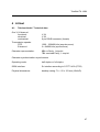
4 Liitteet
A1:
Tekniset tiedot / Technical data:
One V.24 channel:
functional:
electrical:
mechanical:
V.24
V.28
9 pin DSUB connector (female)
Transmission speeds:
DTE:
B channel:
1200 – 230400 bit/s (asynchronous)
2 x 64000 bit/s (synchronous)
Character representation:
8Bit no Parity, 1 stop bit
7Bit even/odd Parity, 1 stop bit
Character synchronization: asynchronous
Operating mode:
half duplex or full duplex
ISDN interface:
S0-interface according to CCITT I.430 (1TR3)
Physical dimensions:
desktop casing: 71 x 22 x 123 mm (WxHxD)
47
TeleWell TA 128K
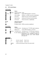
A2:
LED näyttö/display
Active states:
L1
L2
⊗
Θ (1x1s)
⊗
⊗
⊗
⊗
Θ (2sec)
O
O
∅
⊕
⊗
B1,B2
Power-On-Phase ; Wait
ISDN not ok
; Check ISDN interface/ -connector
Active phase
; ISDN ok, no ISDN connection established
Call active
; ISDN Connection will be established
Synch active
; Waiting for B channel synchronization
Connected
; Data connection is established
Status B channels
B channel offline ;
O
⊗
B channel online ; ISDN connection established
Error states:
L1
L2
O
Θ
O
Θ
Status
O
O
Θ (nx1s)
Θ
Status
TA 128K not ok ; Hardware error, TA 128K repair necessary
ISDN not ok
; Check ISDN interface/ -connector
TA 128K not ok ; Hardware error, TA 128K repair necessary
B1, B2 flashing: Bootloader aktive, no operational firmware
programmed. Use command at**flash to
download firmware with 115200 Bd,N81
(see page 42).
LED Legend:
⊗
∅
⊕
Θ
O
48
On
occ
short on, long off
Cycle 1 sec
fl
long on, short off
Cycle 1 sec
(nxms)
continuous blinking: n times every m seconds
Off
TeleWell TA 128K
A3:
ISDN RJ45 kaapelin signaalit
Pinout of the 8 pin ISDN S-interface connector (RJ45) (CCITT I.430/ISO 8877)
Pin
1
2
3
4
5
6
7
8
A4:
Pin
Signal (S0)
Not connected
Not connected
Tx+ (Transmit +)
Rx+ (Receive +)
Rx- (Receive -)
Tx- (Transmit -)
Not connected
Not connected
PRS232 portin signaalit V.24/V.28 / TA 128K (DSUB 9)
V.24/V.28
CCITT
I/O
DIN
TEXT
EIA
1
109
M5
DCD
O
Data carrier detect
2
104
D2
RD
O
Receive data
3
103
D1
TD
I
Transmit data
4
108/1
108/2
S1.1
S1.2
DTR
I
Data terminal ready
5
102
E2
GND
---
Signal ground
6
107
M1
DSR
O
Data set ready
7
105
S2
RTS
I
Request to send
8
106
M2
CTS
O
Clear to send
9
125
M3
RI
O
Ring indicator
49
TeleWell TA 128K
A5:
Cable layout for connection of terminals with 25 pin connectors (male or
female) to a TA 128K
Only the cable with a male plug at the terminal side is shown. The pin configuration
for the female plug is the same.
V.24 device
1
5
2
3
4
5
6
20
8
22
25 pin jack
Attention:
50
shield*
SGND
TD
RD
RTS
CTS
DSR
DTR
DCD
RI
TA 128K
102
103
104
105
106
107
108
109
125
allowed cable length < 15m.
for transmission speeds > 19.200 bit/s < 2m.
* necessary if cable length > 2m
5
3
2
7
8
6
4
1
9
9 pin jack
TeleWell TA 128K
A6:
Cable layout to connect a PC with 9 pin male plug through a serial COMport to a TA 128K
PC
5
3
2
7
8
6
4
1
9
9 pin jack
Attention:
shield*
SGND
TD
RD
RTS
CTS
DSR
DTR
DCD
RI
TA 128K
102
103
104
105
106
107
108
109
125
5
3
2
7
8
6
4
1
9
9 pin jack
allowed cable length < 15m.
for transmission speeds > 19.200 bit/s < 2m.
* necessary if cable length > 2m
51
TeleWell TA 128K
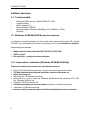
Asiakastuki:
Tämän tuotteen käyttö edellyttää, että käyttäjä hallitsee Windows 95/98/Me tai
Windows NT 4/2000/Xp perustiedot.
Käyttäjällä tulee olla käytettävissä Windows –käyttöjärjestelmän alkuperäinen
asennus CD ja TeleWell TA128K tuotteen alkuperäiset asennuslevyt ja ohjeet.
Easytel Oy:n asiakastuki ei kouluta puhelimitse käyttöjärjestelmän käytössä.
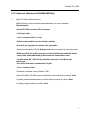
Easytel Oy:n asiakastuen puhelinnumero on 03-610 1850
ja se on käytettävissä vain ensiasennuksen aikana arkisin klo 10-17.
Muu asiakastuki annetaan puhelinnumerossa 0600 92486 ark. 10-17 ja sen hinta on
11,90mk per minuutti + pvm. Hinta on voimassa sitoumuksetta.
Ohjelmistopäivitykset
Bios- ja ajuripäivitykset ovat osoitteessa www.easytel.fi ISDN–ohjelmistot.
52