1
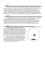
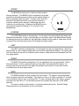
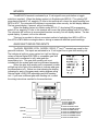
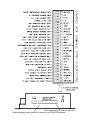
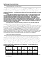
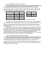
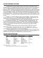
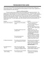
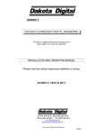
SERIES II
VACUUM FLUORESCENT DIGITAL DASHBOARD
The latest in digital dashboard technology for the
street rodder, car, and truck enthusiast.
INSTALLATION AND OPERATION MANUAL
Please read this before beginning installation or wiring.
MODEL STR6D-GM
92-94 Chevrolet Full Size Pickup kit
3421 W. Hovland Ave.
Sioux Falls, SD 57107
Phone: (605) 332-6513
FAX: (605) 339-4106
Thank you for purchasing the Vacuum Fluorescent Digital Dashboard from DAKOTA
DIGITAL, the leader in custom automotive electronics. Representing the latest electronics
dashboard technology for the street rodder, car, and truck enthusiast alike, the digital
instrumentation uses state of the art vacuum fluorescent display technology to give the driver
up to date and accurate information on the operation of his or her vehicle. As used in several
production automobiles, vacuum fluorescent displays give superior performance and visual
appeal over LCD or LED display systems. Emitting a blue/green light that can be filtered to a
wide variety of colors, the VFD system boasts excellent daytime visibility and while under
computer control, automatically dims for nighttime driving. Using microprocessor technology,
the digital dashboard gives the driver additional features and benefits not typically found on any
other brand or type of instrumentation. Digital accuracy and solid state reliability will give you,
the driver, quality service for miles down the road.
DISPLAY FEATURES
Your DAKOTA DIGITAL instrumentation panel has many features, some of which you
will not be able to see until the instrumentation is completely wired and installed. The odometer
is the bottom display of the speedometer area. This is the same display that will function as the
resettable trip-odometer. The digit furthest to the right of the odometer will become your gear
shift indicator if you purchased the optional gear shift sending unit. Every DAKOTA DIGITAL
instrumentation panel is equipped with this indicator. If you did not originally order a gear shift
sending unit, and would like to have a gear shift indicator, you may order the sending unit at
anytime and when properly installed, the gear shift indicator will operate.
WARNING
The vacuum fluorescent displays are made of glass and should be handled with care. Use extreme care
around the glass evacuation tubes (small tubes at the bottom of each display) as bumping them may cause
breakage and render the display useless.
INSTALLING THE DISPLAY SYSTEM
The first step in installing your new digital gauge kit will be to remove the instrumentation
cluster from your vehicle. The front plastic bezel must be removed first. Once this has been
taken off, you can begin removing the instrument cluster. There are four screws which hold the
instrument cluster in, two on each side. It may be necessary to move the heater vent duct or
radio to get to the screws.
Once the instrument cluster has been removed, take the four screws out which hold the
black hood onto the cluster. Remove the hood. Turn the gauge housing over so you can see
the back side. Unplug the four wire, black connector found in the center of the back side.
Remove the six large gray light bulbs. Do not remove any of the small gray bulbs, or the large
black bulb by the gear shift position indicator. The bulbs are taken out by rotating it counterclockwise 1/8 turn and then pulling it. Turn the housing back over so the front is facing you.
The gauges consist of a single panel which can be pulled out of the housing. Remove this since
they will no longer be used. The pin connections for the gauge panel holds it in very tightly so
some force will be required. Start by working gently along the outside edges. Once it is out,
you will see a small green circuit panel in the lower right side of the housing. Remove this also.
You are now ready to install the digital gauge panel. The screws sticking out of the back
side will insert into the housing to make connection with the vehicle senders and wiring. The
colored wires and flat gray cable coming out of the back side of the display panel will be routed
out the hole in the center of the housing. Carefully place the display panel into the housing and
press down evenly on the display panel until it hits the bottom and stops.
Place a washer and nut onto a screw sticking out of the back side of the housing. This
will help ensure that the display panel does not vibrate loose.
You are now ready to install the new lens onto the hood. Remove the two screws on the
top side of the instrument cluster hood which hold the curved plastic lens on. Set the clear
plastic lens aside. Place a bead of clear or black silicone RTV around the bottom inside edge of
the hood from the front side. The lens will be placed onto the front, inside lip of the hood and
the RTV will hold it into place. The RTV will need several hours to cure before the hood can be
placed back onto the instrument housing.
Once the RTV has cured, place the hood and curved plastic lens back onto the housing
and secure it using the six screws that were originally in it.
The wires coming out of the back of the housing will connect to the control box terminal
strip. See the following section for wire color and location. After connecting the wires, the
gauge housing is ready to go back into the dash. Reverse the disassembly procedure to put
your dash back together. The control box can be mounted up under the dash or against the fire
wall. The control box can be secured using screws, Velcro, or nylon cable ties. The system
uses the original vehicle senders so you are now ready to drive away.
CONTROL BOX
Once the display panel is in place, mount the control box within the connecting cable's
distance (approximately 3 feet) and secure to the underside of the dashboard. This case does
not have to be mounted to metal, but by doing so you will provide a better ground to the control
box. When connecting the display cable to the unit, be very sure to pay attention to the "up"
side of the connector. Align the connector in the socket and press firmly into the control box.
The connector locks will secure the connector.
Wiring the control box into the vehicle.
+12V
Connect the +12V terminal to the RED wire from the display panel.
Never connect this to a battery charger alone. It needs to have a 12 volt battery
connected to it. Battery chargers have an unregulated voltage output that will cause the system
to not operate properly.
GROUND
This is the main ground for the display system. Connect the BLACK wire from the
display panel to this terminal.
Proper vehicle grounding is extremely important for the gauges to read and operate
correctly. The engine block should have heavy ground cables to the battery, frame, and body.
Failure to properly ground the engine block or the control box can cause incorrect or erratic
operation.
DIMMING
The gauges are designed to dim down when the headlights are turned on. This is to
reduce the display intensity at night so the gauges do not cause eye strain or reduced night
vision.
In order for the automatic dimming feature fo the display system to operate properly, the
“DIM” terminal must be connected to the park light circuit. The WHITE wire supplied with the
system can be used to connect the DIM terminal to the park light circuit on your headlight
switch. This will be a brown wire on position “A” of the headlight switch connector. The display
system will dim whenever the “DIM” terminal has 12 volts applied to it. The night brightness
level is adjustable two different ways.
The default method is to have the system to dim to a preset level when the lights are
turned on. This brightness is adjusted by turning the shaft protruding from right side of the
control box, next to the display system connector. Turning the shaft clockwise will decrease the
brightness. The shaft will rotate ¾ turn from stop to stop. Do not attempt turn it past the stops.
See DIM ADJ for a description of the second method.
DIM ADJ
The second method allows you to have a dash mounted control to vary the brightness
while the headlights are on. This requires a 10k potentiometer or Dakota Digital’s DIM-1 kit. A
stock headlight rheostat will not work. The dash mount dimmer has two wires, one connects to
the DIM ADJ terminal and the other connects to ground. To allow the dash mount dimmer to
have full control, the shaft on the side of the control box must be turned fully counter-clockwise.
The dash mount dimmer will only vary the display brightness when the DIMMING terminal has
power.
SPEED
The BROWN wire from the display panel connects to the SPEED terminal.
This system can accept 4000 ppm – 128000 ppm speed signals. The control box has
been pre-calibrated to the 4000ppm signal from the display panel. The speedometer is fully
adjustable and calibration is discussed in a later section.
TACH
Connect the tach terminal to the YELLOW wire coming from the display panel. DO NOT
USE SOLID CORE SPARK PLUG WIRES WITH THIS DASHBOARD SYSTEM. Solid core
ignition wires cause a large amount of electromagnetic and radio frequency interference which
can disrupt the system operation.
The tachometer is compatible with 4, 6, 8, and 10 cylinder gasoline engines. There are
DIP programming switches inside the control box that set the number of cylinders, tach bar
graph full scale range, and tach display type. These settings are discussed later in the section
on internal adjustments.
WATER
This system is designed to use an original equipment General Motors water temperature
gauge sender. Other senders will cause incorrect readings. The sender mounts on the engine
block so that the end of the sensor is in the engine coolant flow.
Connect the GREEN wire from the display panel to the control box terminal marked
WATER. If the water display shows “---“ this indicates that the control box is sensing a short to
ground or out-of-range error from the sender or sender wire. If the water display shows “EEE”
this indicates that the control box is sensing an open circuit or out-of-range error from the
sender or sender wire. If either indication remains on the display, inspect the sender wire for
damage, check the routing of the sender wire, check the sending unit grounding, and check that
the correct sending unit is connected.
OIL
This system is designed to use an original equipment General Motors 80 psi oil pressure
sender. Other senders will cause incorrect readings.
Connect the GRAY wire from the display panel to the control box terminal marked OIL. If
the oil display shows “EE” this indicates that the control box is sensing an open circuit or out-ofrange error from the sender. If either indication remains on the display, inspect the sender wire
for damage, check the routing of the sender wire, check the sending unit grounding, and check
that the correct sending unit is connected.
FUEL
Connect the PURPLE wire from the display panel to the control box terminal marked
FUEL. The fuel sender type is selected using the DIP programming switches located inside the
control box. The settings are discussed later in the section on internal adjustments.
If the fuel display shows “—“ this indicates that the control box is sensing a short to
ground or out-of-range error from the sender or sender wire. If the fuel display shows “EE” this
indicates that the control box is sensing an open circuit or out-of-range error from the sender. If
either indication remains on the display, inspect the sender wire for damage, check the routing
of the sender wire, check the sending unit grounding, and check that the DIP programming
switches are set correctly for the sending unit that is connected.
TRIP
The TRIP terminal is used for the trip odometer function, for setting the oil warning set
point (see WRN), and for speedometer calibration (see SPEEDOMETER CALIBRATION). The
TRIP input is activated by a ground connection. The push button switch supplied (or any
normally open switch) is wired by connecting one terminal to TRIP and the other terminal to a
ground. When the trip button is pressed, the odometer display will switch from full odometer
mileage to the trip mileage or from the trip mileage to the full odometer mileage. When the trip
mileage is shown a lower case “t” will be displayed to the left of the trip meter reading. “t 000.0”
RESET
The RESET terminal is used for the trip odometer function, for setting the water warning
set point (see WRN), and for the speedometer calibration (see SPEEDOMETER
CALIBRATION). The RESET input is activated by a ground connection. The push button
switch supplied (or any normally open switch) is wired by connecting one terminal to RESET
and the other terminal to a ground. When the reset button is pressed and held for a few
seconds, the trip miles will be reset to zero. This will not affect the full odometer mileage.
CHECK
The check engine terminal is used with fuel
injection ECM’s to display engine problems and trouble
codes. The CHECK input is activated by a ground signal
from the ECM. Whenever the check input is grounded
the system will display a lower case “c” to the right of the
speedometer. When the ECM is placed into diagnostic
mode trouble codes can be read by counting the flashes.
Consult a service manual for the fuel injection system
that you have for further information on trouble codes.
With some ECM’s a 12 volt light bulb may need to
be connected in addition to our CHECK input in order to
provide proper current loading. In this case both the
bulb and our display system indicator would both come
on when the check engine wire was set.
BRAKE
The BRAKE terminal can be used as a brake system
warning indicator. The BRAKE input is activated by a ground
signal from the brake pressure switch on the master cylinder or
from the parking brake set switch. Connect a wire from this
terminal to the pressure switch on the master cylinder or
consult a vehicle service manual to determine color and
location of an existing wire. Whenever the BRAKE input is
grounded the system will display a “b” to the left of the
speedometer.
HI BEAM
The HI BEAM terminal is activated by a 12 volt signal from the headlight high beam wire.
When the terminal has 12 volts, a dot will light up to the lower right of the speedometer display.
An existing wire from the vehicle for the high beam indicator can be used or a new wire can be
connected from the high beam side of the hi beam/low beam switch.
LEFT
The LEFT terminal is activated by a 12 volt signal from the turn signal switch. When this
terminal has 12 volts, a dash will light up to the left of the speedometer display. An existing wire
from the vehicle for the left turn indicator can be used or a new wire can be connected from the
turn signal switch.
RIGHT
The RIGHT terminal is activated by a 12 volt signal from the turn signal switch. When
this terminal has 12 volts, a dash will light up to the right of the speedometer display. An
existing wire from the vehicle for the right turn indicator can be used or a new wire can be
connected from the turn signal switch.
WRN
The WRN terminal is a dual function input and output. The output is ground-activated
when the preset rpm limit is exceeded. This output can turn on a 4 Watt or smaller 12 volt bulb
or can activate a relay to turn on a larger bulb. To wire a warning light to this output, connect
one wire from the bulb to 12 volt accessory power and connect the other wire to the WRN
terminal.
The input is used to set the water, oil, and rpm warning set points. See the Gauge
Warning section for a description of how to set these.
MPH/KPH
The MPH/KPH terminal is activated by a 12 volt signal from a push button or toggle
switch(not supplied). When the display system is in English mode (MPH & °F) by placing DIP
programming switch #7 off, applying 12 volts to this terminal will convert the speed reading from
MPH to KPH. The odometer will continue to accumulate miles correctly, but will display dashes.
The bar speed display, if present, will not be affected.
When the display system is in Metric mode (KPH & °C) by placing DIP programming
switch #7 on, applying 12 volts to this terminal will convert the speed reading from KPH to MPH.
The odometer will continue to accumulate kilometers correctly, but will display dashes. The bar
speed display, if present, will not be affected.
This input is provided to allow a convenient method of switching from MPH to KPH or
from KPH to MPH while crossing borders or driving in areas with different speed markings.
GEAR SHIFT INDICATOR INPUTS
The PARK, REVERSE, NTRL, OVRDRV, DRIVE, 2nd,and 1st terminals are used for the
gear shift indicator. The inputs are activated be a 12 volt signal from a gear shift sending unit.
The indicator is built into every system but it will not light up
unless a Dakota Digital GSS-1000 or compatible gear shift
sending unit is connected to tell it what gear the
transmission is in. The gear shift sending unit is not
included with the system and must be purchased separately.
When the gear shift sending unit is connected, a letter
will light up to the right of the odometer to indicate what gear
the transmission is in. Below is a chart showing the display
indicators for each of the gears and a wiring diagram using
Dakota Digital’s GSS-1000 adjustable gear shift sending
unit. If you have a different gear shift sending unit, consult
the wiring instructions supplied by the manufacturer.
Safety
Backup
Power
Dim
Park
Reverse
Neutral
Overdrv
Drive
Second
First
HI
Signal
Ground
GSS-1000
DECODER
+12V
to Chassis Ground
to sensor BLACK wire
to sensor GREEN wire
to sensor RED wire
to control box FIRST terminal
to control box SECOND terminal
to control box DRIVE terminal
to control box OVERDRIVE terminal
to control box NEUTRAL terminal
do not connect
to control box REVERSE terminal
to control box PARK terminal
(optional)
(optional)
Insert cable with red stripe to right side.
Optional display power connector used only on STR4D/5D systems.
Setting up the control box
SPEEDOMETER CALIBRATION
The speedometer calibration is done using the TRIP and RESET switches. There are
two different ways to calibrate the speedometer. The first method control box uses an auto-cal
mode where you drive one mile (1 km for metric) and the system automatically adjusts the
speedometer calibration. The second method allows you to adjust the speedometer up or down
as you drive.
To enter the auto-calibration mode, begin with the key off. Press and hold both the trip
and reset switches at the same time while the vehicle is started. The speed will display “CAL”.
Once the switches are released the control box will begin measuring. As you drive the
odometer will display the number of pulses received from the sensor. If the reading stays at
zero as you drive, then check the vehicle speed sensor and speed sensor wiring. Once you
have driven exactly one mile (or km) press and hold both of the switches again. The system will
calculate and store the new speed calibration. Once the switches are released the system will
restart and go back to normal operation.
While the system is in the auto-cal mode the voltage, fuel, oil, and water gauges will
remain blank will not change until the speed calibration is completed.
To enter the speedometer adjust mode, press and hold both the trip and reset switches at
the same time while the system is on and operating. The switches will need to be held for about
4-6 seconds. The odometer will display “AdJUSt” and the other gauges will function normally.
Release the switches. Pressing and holding the TRIP switch will increase the speedometer
reading. Pressing and holding the RESET switch will decrease the speedometer reading.
Pressing and holding both the TRIP and RESET switches at the same time will store the current
speed calibration and exit the speed adjust mode. While the system is in speed adjust mode
the odometer will continue to accumulate normally, even though it is not displayed.
FUEL DIP SWITCH SETTINGS
The control box can read 5 different types of fuel senders. The DIP programming
switches are located inside the control box, so the cover must be carefully removed to get
access to the switches. Make sure the key is turned off before opening up the control box so
that there is no power to the system. The switches labeled 1, 2, and 3 are used to select the
different sender types. Once the switches have been set, replace the cover before turning the
system on. The sender types are listed below, along with their corresponding empty and full
resistance readings. If you do not know what type of sender you have, use an ohmmeter to
measure the fuel sender resistance when it is full and empty. Ford fuel senders are not
supported with this system.
Sender type
Empty R
Full R
Switch #1
Switch #2
Switch #3
GM 0-30 ohm
GM 0-90 ohm
0 ohms
0 ohms
30 ohms
90 ohms
ON
OFF
ON
ON
OFF
OFF
FORD
VDO
73 ohms
10 ohms
10 ohms
180 ohms
OFF
OFF
OFF
SW/SUN
240 ohms 33 ohms
OFF
ON
ON
SW/SUN is the default setting when systems are shipped unless it was requested to be
set differently.
TACHOMETER DIP SWITCH SETTINGS
The control box will work with 4, 6, 8, and 10 cylinder ignition systems. The DIP
programming switches are located inside the control box, so the cover must be carefully
removed to get access to the switches. Make sure the key is turned off before opening up the
control box so that there is no power to the system. The switches numbers 5 and 6 select the
number of engine cylinders. The settings are as follows:
Engine cylinders Switch #5 Switch #6
Bar tach Switch #4
4
6
8
10
ON
OFF
ON
OFF
ON
ON
OFF
OFF
6000 rpm
8000 rpm
OFF
ON
The default setting when systems are shipped from the factory is 8 cylinder.
In addition, the tachometer bar graph can be set to read 6000 rpm at full scale(switch #4
OFF) or 8000 rpm at full scale(switch #4 ON). This option would have been specified when the
order was originally placed and the switch should be set to match the display system lens
engraving. Systems with both a digital and bar graph tachometer are always set for 8000 full
scale(switch #4 ON).
Because some systems have a digital speedometer with a bar graph tachometer directly
above it(88 Chevy pickup) and some systems a have separate digital speedometer and digital
tachometer, each having their own bar graph readout(94 Chevy pickup), switch #8 selects which
style display system is being used. For 5-gauge systems with a bar graph tachometer directly
above the speedometer, turn switch #8 OFF. For 6-gauge systems with a bar graph
speedometer directly above the digital speedometer, turn switch #8 ON. This is set correctly at
the factory before shipping to match the display system that it is paired with.
METRIC SELECTION DIP SWITCH SETTINGS
Switch #7 selects whether the temperature will be displayed in °F or °C and also sets the
speedometer for MPH or KPH. For MPH/°F turn switch #7 OFF. For KPH/°C turn switch #7
ON. Changing switch #7 does not change the speedometer calibration. Speedometer
calibration is discussed in another section. This switch will be set from the factory to match the
display system lens engraving. If this is changed, a new lens should be purchased so that the
labeling matches the gauge readings.
GAUGE WARNING FEATURE
The gauges have the built in feature to alert you when they are outside their normal
operation range. The fuel display will flash whenever the fuel level is below 10% to indicate low
fuel. The voltage gauge will flash whenever the system voltage is below 11.0 volts and the
engine is running. The water gauge will flash whenever the temperature is higher than the water
warning set point. The oil gauge will flash whenever the oil pressure is below the oil warning set
point and the engine is running. The WRN output will be activated whenever the rpm warning
set point is exceeded. A single. lit bar on the right half of the rpm bar display shows the current
rpm warning set point. The rpm warning set point can either be used as a shift indication or as a
red line indication. The rpm warning output is triggered off the bar tach and is updated every 1/8
second.
The water, oil, and rpm warning set points are user adjustable. They are preset at the
factory to 250 for water, 10 for oil, 4560 for 6000 bar tachs, and 6080 for 8000 bar tachs. The
warning set points are adjusted using the TRIP, RESET, and WRN terminals.
To enter the warning adjust mode, ground the WRN terminal while the system is turned
on. The speedometer will display “AdJ”. Release the ground from the WRN terminal. The
current warning set points will be displayed. The RESET, TRIP, and WRN inputs adjust the
water, oil, and rpm warning set points respectively. Once the set points have been changed, if
an input is not activated for 8 seconds the values will be saved and the system will begin
operating normally.
To change the water warning set point, press and hold the RESET button until the
desired value is shown. The range is from 194 – 254°F in 2° increments (90 – 123°C).
To change the oil warning set point, press and hold the TRIP button until the desired
value is shown. The range is from 2 – 30 psi in 2 psi increments.
To change the rpm warning set point, ground the WRN terminal until the desired value is
displayed. For 0-6000 bar tachs, the range is from 2160-5760 rpm in 120 rpm increments. For
0-8000 bar tachs, the range is from 2880-7680 rpm in 160 rpm increments.
GAUGE SPECIFICATIONS
Gauge
WATER
OIL
FUEL
VOLT
SPEED
ODOMETER
TRIP METER
TACH bar
TACH digital
Minimum reading
Maximum reading
0°F (0°C)
299°F (148°C)
0 psi
80 psi
0% (empty)
99% (full)
8.0 volts
18.0 volts
0 mph (kph)
255 mph (kph)
00000.0 miles (km)
99999.9 miles (km)
000.0 miles (km)
999.9 miles (km)
400 rpm
6000 rpm or 8000 rpm
400 rpm
9990 rpm
Power requirements:
11 – 15 volts dc
(Battery charges cannot be used for powering or testing this system.)
Resolution
1 - 2°
1 psi
1 - 3%
0.1 volt ±0.1
1
0.1
0.1
120 or 160
10
TROUBLESHOOTING GUIDE
This is a list of some problems and their solutions which may be encountered when installing your
instrumentation system. If you cannot determine what the problem is or how to solve it, please call our
technical assistance line (605) 332-6513.
* A note on vehicle grounding. *
The most common cause of problems with electric gauges is poor ground connections. The
engine block has the highest ground currents of any point in the vehicle. The ignition system, electric
gauge senders, starter, alternator, etc. all use the engine block for a ground point. Since the alternator is
grounded directly to the engine block all ground currents in the entire vehicle must pass through the
engine block while the engine is running. A weak or loose connection can cause all kinds of random
problems that may difficult to track down. The engine block should have heavy ground straps to both the
chassis and the body. The main negative cable from the battery should be connected directly to the
engine block.
Symptom
Possible Problem
Solution
----------------------------------------------------------------------------------------------------------------------------------System does not light up.
Control box may not be getting
Check if the control box has
power.
12 volts connected to it.
Do not use a battery charger to
power the system.
Check the fuse inside the control
box. If it is blown, replace with a
2 amp fuse.
The display system may not be
Insert the connector on the
getting power.
display system wiring harness
into the slot on the side of the
control box. Be sure the pins
line up properly.
Check the display system wiring
harness for broken or cut wires.
The control box may have
Return the control box to Dakota
an internal problem
Digital with a description of the
problem and a phone number.
A display shows dashes.
The sending unit for that display
is not connected to the control
box.
Check the wire from sending unit
to the control box for breaks.
Make sure that the sending unit is
wired to the correct terminal.
Make sure the sending unit is
grounded properly.
One display does not
light up.
If the circle in the upper right
corner of the display is white,
the display is cracked or broken
Return the display panel to
Dakota Digital for repair. Include
a phone number and address.
The tachometer will not
show a reading.
The control box is not connected
to the engine properly
Make sure the control box is
connected to your particular
system properly.
Symptom
Possible Problem
Solution
----------------------------------------------------------------------------------------------------------------------------------The tachometer reading
The tachometer signal wire is
Check the connections at both
is incorrect.
loose or broken.
ends of the wire.
The control box is not set up for
Refer to the Internal Adjustments
the proper number of cylinders
section of the installation manual
or the proper tach range.
to set the control box properly.
The speedometer will
not show a reading.
The speed sending unit is not
connected to the control box
properly.
The speed sending unit is not
connected to the transmission
properly.
The sending unit wire is picking
up noise from nearby wires.
The vehicle speed buffer is not
working correctly.
The fuel display reads
backwards, incorrectly,
or does not change.
The control box may be set for
the wrong type of fuel sender.
The fuel sender may not be
connected to the control box
properly.
The fuel sender may not be
operating properly.
The fuel sender may have a
non-standard resistance
range.
The oil or water display
reading is incorrect.
The engine block may not be
grounded to the chassis frame
or body properly.
The sending unit wire is picking
up noise from nearby wires.
The sending unit is not
compatible with the control box
The sending unit has failed.
Check that both speed sending
unit wires are connected to the
control box properly.
Check that sender is mounted
properly.
Check that transmission has the
appropriate internal parts.
Isolate the sending unit wire from
motor and ignition wires.
Check the stock VSS buffer according
to the GM service manual.
Refer to the Internal Adjustments
section of the installation manual
to ensure that the settings match
your fuel sender.
Check the connections at both
ends of the fuel sender wire.
Make sure the fuel sender is
grounded properly.
Check the fuel sending unit with
a mechanical gauge or an
electrical multi-meter.
If the proper resistance range
setting is not available with
the control box settings, replace
the fuel sender with a different
style.
Use heavy ground cables from the
battery to the engine block.
Make sure both ends of the cable
have clean metal-to-metal
connections.
Use a braided ground strap to
ground the engine block to the
chassis.
Use a large braided ground strap
to ground the engine block to
the body or fire wall.
Isolate the sending unit wire from
motor and ignition wires.
Use the appropriate GM gauge
sending unit.
Replace the sending unit
Symptom
Possible Problem
Solution
----------------------------------------------------------------------------------------------------------------------------------The gear shift indicator
The optional gear shift sending
Connect the sending unit to the
does not light up.
unit is not connected to the
control box using the
control box.
instructions supplied with the
sending unit.
The gear shift indicator
does not operate
properly.
The gear shift sending unit
is not connected properly.
Check the connections to the
transmission linkage and to
the control box.
Connect 12 volts to the sending
unit power wire.
The colored bulbs in
the display panel for
turn signals and high
beam do not light up.
(not found on all units)
The LED bulbs are not
connected into the auto's
electrical system.
(these are not wired into the
display system control box)
Connect the wires found on the
back of the aluminum panel
to your cars electrical system
as explained in the Optional
Indicators section of the manual.
The internal turn signal
and high beam
indicators do not light up.
The control box is not connected
to the vehicle's electrical
system properly.
Check the wires connected to the
HIGH, LEFT, and RIGHT
terminals on the control box.
The check engine
indicator does not
operate properly.
The control box is not connected
to a TPI control module.
This feature is designed to work
with engine control systems that
provide an active low signal.
The check engine
indicator stays on
all of the time.
The Engine Control Module
(ECM) needs to see the
load of a light connected to it.
Connect a light or similar load
to the ECM along with the
control box.
Trip select and trip reset
functions do not operate
properly.
Select and reset switches are
not connected to the control
box.
Momentary push-button or toggle
switches must be connected to
the TRIP and RESET terminals
as described in the Trip meter
section of the installation manual
The switch terminal connected
to the control box should
normally be open. When the
the switch is activated, the
terminal should make contact
to ground.
Disconnect or replace the trip
select switch.
The wrong type of switch is
being used.
The display system starts
up in the demonstration
mode and remains in it.
The TRIP terminal is constantly
connected to ground.
4510 W. 61ST St. N., Sioux Falls, SD 57107
Phone: (605) 332-6513 FAX: (605) 339-4106
www.dakotadigital.com
[email protected]
©Copyright 2001 Dakota Digital Inc.