1
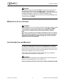
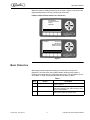
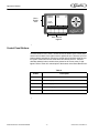
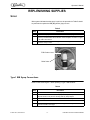
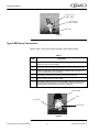
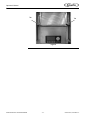
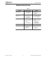
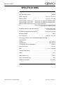
FRUTISTA VIPER 3 FLAVOR Operator’s Manual Release Date: April 2, 2010 Publication Number: 621360041TBOPR Revision Date: April 28, 2014 Revision: D Visit the Cornelius web site at www.cornelius.com for all your Literature needs. The products, technical information, and instructions contained in this manual are subject to change without notice. These instructions are not intended to cover all details or variations of the equipment, nor to provide for every possible contingency in the installation, operation or maintenance of this equipment. This manual assumes that the person(s) working on the equipment have been trained and are skilled in working with electrical, plumbing, pneumatic, and mechanical equipment. It is assumed that appropriate safety precautions are taken and that all local safety and construction requirements are being met, in addition to the information contained in this manual. This Product is warranted only as provided in Cornelius’ Commercial Warrant applicable to this Product and is subject to all of the restrictions and limitations contained in the Commercial Warranty. Cornelius will not be responsible for any repair, replacement or other service required by or loss or damage resulting from any of the following occurrences, including but not limited to, (1) other than normal and proper use and normal service conditions with respect to the Product, (2) improper voltage, (3) inadequate wiring, (4) abuse, (5) accident, (6) alteration, (7) misuse, (8) neglect, (9) unauthorized repair or the failure to utilize suitably qualified and trained persons to perform service and/or repair of the Product, (10) improper cleaning, (11) failure to follow installation, operating, cleaning or maintenance instructions, (12) use of “non-authorized” parts (i.e., parts that are not 100% compatible with the Product) which use voids the entire warranty, (13) Product parts in contact with water or the product dispensed which are adversely impacted by changes in liquid scale or chemical composition. Contact Information: To inquire about current revisions of this and other documentation or for assistance with any Cornelius product contact: www.cornelius.com 800-238-3600 Trademarks and Copyrights: This document contains proprietary information and it may not be reproduced in any way without permission from Cornelius. This document contains the original instructions for the unit described. CORNELIUS INC 101 Regency Drive Glendale Heights, IL Tel: + 1 800-238-3600 Printed in U.S.A. TABLE OF CONTENTS Safety Instructions. . . . . . . . . . . . . . . . . . . . . . . . . . . . . . . . . . . . . . . . . . . . . . . . . . . . . . . . . . . . . . . . 1 Read and Follow ALL Safety Instructions . . . . . . . . . . . . . . . . . . . . . . . . . . . . . . . . . . . . . . . . . . . . 1 Safety Overview . . . . . . . . . . . . . . . . . . . . . . . . . . . . . . . . . . . . . . . . . . . . . . . . . . . . . . . . . . 1 Recognition . . . . . . . . . . . . . . . . . . . . . . . . . . . . . . . . . . . . . . . . . . . . . . . . . . . . . . . . . . . . . 1 Different Types of Alerts. . . . . . . . . . . . . . . . . . . . . . . . . . . . . . . . . . . . . . . . . . . . . . . . . . . . . . . 1 Safety Tips . . . . . . . . . . . . . . . . . . . . . . . . . . . . . . . . . . . . . . . . . . . . . . . . . . . . . . . . . . . . . . . . . . . . 1 Qualified Service Personnel. . . . . . . . . . . . . . . . . . . . . . . . . . . . . . . . . . . . . . . . . . . . . . . . . . . . . . . 2 Safety Precautions. . . . . . . . . . . . . . . . . . . . . . . . . . . . . . . . . . . . . . . . . . . . . . . . . . . . . . . . . . . . . . 2 Shipping And Storage . . . . . . . . . . . . . . . . . . . . . . . . . . . . . . . . . . . . . . . . . . . . . . . . . . . . . . . . . . . 2 CO2 (Carbon Dioxide) Warning . . . . . . . . . . . . . . . . . . . . . . . . . . . . . . . . . . . . . . . . . . . . . . . . . . . . 3 Mounting in or on a Counter . . . . . . . . . . . . . . . . . . . . . . . . . . . . . . . . . . . . . . . . . . . . . . . . . . . . . . 3 Cart Information and Mounting . . . . . . . . . . . . . . . . . . . . . . . . . . . . . . . . . . . . . . . . . . . . . . . . . . . . 3 System Overview . . . . . . . . . . . . . . . . . . . . . . . . . . . . . . . . . . . . . . . . . . . . . . . . . . . . . . . . . . . . . . . . . 4 Cart Information and Mounting . . . . . . . . . . . . . . . . . . . . . . . . . . . . . . . . . . . . . . . . . . . . . . . . . . . . 4 Beginning Operation . . . . . . . . . . . . . . . . . . . . . . . . . . . . . . . . . . . . . . . . . . . . . . . . . . . . . . . . . . . . 4 Basic Operation . . . . . . . . . . . . . . . . . . . . . . . . . . . . . . . . . . . . . . . . . . . . . . . . . . . . . . . . . . . . . . . . 5 Dispensed Product Throughput . . . . . . . . . . . . . . . . . . . . . . . . . . . . . . . . . . . . . . . . . . . . . . . . . 6 Barrel Status Lights . . . . . . . . . . . . . . . . . . . . . . . . . . . . . . . . . . . . . . . . . . . . . . . . . . . . . . . . . . . . . 6 Control System Operation . . . . . . . . . . . . . . . . . . . . . . . . . . . . . . . . . . . . . . . . . . . . . . . . . . . . . . . . 7 Control System Overview. . . . . . . . . . . . . . . . . . . . . . . . . . . . . . . . . . . . . . . . . . . . . . . . . . . . . . 7 Control Panel Display. . . . . . . . . . . . . . . . . . . . . . . . . . . . . . . . . . . . . . . . . . . . . . . . . . . . . . . . . 7 Control Panel Buttons . . . . . . . . . . . . . . . . . . . . . . . . . . . . . . . . . . . . . . . . . . . . . . . . . . . . . . . . 8 Replenishing Supplies . . . . . . . . . . . . . . . . . . . . . . . . . . . . . . . . . . . . . . . . . . . . . . . . . . . . . . . . . . . . 9 Syrup . . . . . . . . . . . . . . . . . . . . . . . . . . . . . . . . . . . . . . . . . . . . . . . . . . . . . . . . . . . . . . . . . . . . . . . . 9 Type 1 BIB Syrup Connections . . . . . . . . . . . . . . . . . . . . . . . . . . . . . . . . . . . . . . . . . . . . . . . . . 9 Type 2 BIB Syrup Connections . . . . . . . . . . . . . . . . . . . . . . . . . . . . . . . . . . . . . . . . . . . . . . . . 10 CO2 . . . . . . . . . . . . . . . . . . . . . . . . . . . . . . . . . . . . . . . . . . . . . . . . . . . . . . . . . . . . . . . . . . . . . . . . 11 CO2 (Carbon Dioxide) Warning . . . . . . . . . . . . . . . . . . . . . . . . . . . . . . . . . . . . . . . . . . . . . . . . 11 Replenishing CO2 Supply . . . . . . . . . . . . . . . . . . . . . . . . . . . . . . . . . . . . . . . . . . . . . . . . . . . . 11 Water . . . . . . . . . . . . . . . . . . . . . . . . . . . . . . . . . . . . . . . . . . . . . . . . . . . . . . . . . . . . . . . . . . . . . . . 11 Water Filters. . . . . . . . . . . . . . . . . . . . . . . . . . . . . . . . . . . . . . . . . . . . . . . . . . . . . . . . . . . . . . . 11 Maintaining Product Quality . . . . . . . . . . . . . . . . . . . . . . . . . . . . . . . . . . . . . . . . . . . . . . . . . . . 12 Intelligent Defrost System . . . . . . . . . . . . . . . . . . . . . . . . . . . . . . . . . . . . . . . . . . . . . . . . . 12 Sleep Mode Recommendations . . . . . . . . . . . . . . . . . . . . . . . . . . . . . . . . . . . . . . . . . . . . . 12 Viscosity Setting. . . . . . . . . . . . . . . . . . . . . . . . . . . . . . . . . . . . . . . . . . . . . . . . . . . . . . . . . 12 Maintenance . . . . . . . . . . . . . . . . . . . . . . . . . . . . . . . . . . . . . . . . . . . . . . . . . . . . . . . . . . . . . . . . . . . . 13 Daily Maintenance . . . . . . . . . . . . . . . . . . . . . . . . . . . . . . . . . . . . . . . . . . . . . . . . . . . . . . . . . . . . . 13 Monthly Maintenance. . . . . . . . . . . . . . . . . . . . . . . . . . . . . . . . . . . . . . . . . . . . . . . . . . . . . . . . . . . 13 Cleaning Air Filter . . . . . . . . . . . . . . . . . . . . . . . . . . . . . . . . . . . . . . . . . . . . . . . . . . . . . . . . . . 13 Troubleshooting . . . . . . . . . . . . . . . . . . . . . . . . . . . . . . . . . . . . . . . . . . . . . . . . . . . . . . . . . . . . . . . . 15 Specifications . . . . . . . . . . . . . . . . . . . . . . . . . . . . . . . . . . . . . . . . . . . . . . . . . . . . . . . . . . . . . . . . . . 16 Operator’s Manual SAFETY INSTRUCTIONS READ AND FOLLOW ALL SAFETY INSTRUCTIONS Safety Overview • • Read and follow ALL SAFETY INSTRUCTIONS in this manual and any warning/caution labels on the unit (decals, labels or laminated cards). Read and understand ALL applicable OSHA (Occupational Safety and Health Administration) safety regulations before operating this unit. Recognition Recognize Safety Alerts ! This is the safety alert symbol. When you see it in this manual or on the unit, be alert to the potential of personal injury or damage to the unit. Different Types of Alerts ! DANGER: Indicates an immediate hazardous situation which if not avoided WILL result in serious injury, death or equipment damage. ! WARNING: Indicates a potentially hazardous situation which, if not avoided, COULD result in serious injury, death, or equipment damage. ! CAUTION: Indicates a potentially hazardous situation which, if not avoided, MAY result in minor or moderate injury or equipment damage. SAFETY TIPS • • • • © 2010-2014, Cornelius Inc. Carefully read and follow all safety messages in this manual and safety signs on the unit. Keep safety signs in good condition and replace missing or damaged items. Learn how to operate the unit and how to use the controls properly. Do not let anyone operate the unit without proper training. This appliance is not intended for use by very young children or infirm -1- Publication Number: 621360041TBOPR Operator’s Manual • persons without supervision. Young children should be supervised to ensure that they do not play with the appliance. Keep your unit in proper working condition and do not allow unauthorized modifications to the unit. QUALIFIED SERVICE PERSONNEL ! WARNING: Only trained and certified electrical, plumbing and refrigeration technicians should service this unit. ALL WIRING AND PLUMBING MUST CONFORM TO NATIONAL AND LOCAL CODES. FAILURE TO COMPLY COULD RESULT IN SERIOUS INJURY, DEATH OR EQUIPMENT DAMAGE. SAFETY PRECAUTIONS This unit has been specifically designed to provide protection against personal injury. To ensure continued protection observe the following: ! WARNING: Disconnect power to the unit before servicing following all lock out/tag out procedures established by the user. Verify all of the power is off to the unit before any work is performed. Failure to disconnect the power could result in serious injury, death or equipment damage. ! CAUTION: Always be sure to keep area around the unit clean and free of clutter. Failure to keep this area clean may result in injury or equipment damage. SHIPPING AND STORAGE ! CAUTION: Before shipping, storing, or relocating the unit, the unit must be sanitized and all sanitizing solution must be drained from the system. A freezing ambient environment will cause residual sanitizing solution or water remaining inside the unit to freeze resulting in damage to internal components. CO2 (CARBON DIOXIDE) WARNING Publication Number: 621360041TBOPR -2- © 2010-2014, Cornelius Inc. Operator’s Manual ! DANGER: CO2 displaces oxygen. Strict attention MUST be observed in the prevention of CO2 gas leaks in the entire CO2 and soft drink system. If a CO2 gas leak is suspected, particularly in a small area, IMMEDIATELY ventilate the contaminated area before attempting to repair the leak. Personnel exposed to high concentrations of CO2 gas experience tremors which are followed rapidly by loss of consciousness and DEATH. MOUNTING IN OR ON A COUNTER ! WARNING: When installing the unit in or on a counter top, the counter must be able to support a weight in excess of 450 lbs. to insure adequate support for the unit. FAILURE TO COMPLY COULD RESULT IN SERIOUS INJURY, DEATH OR EQUIPMENT DAMAGE. Note: Many units incorporate the use of additional equipment such as ice makers. When any addition equipment is used you must check with the equipment manufacturer to determine the additional weight the counter will need to support to ensure a safe installation. CART INFORMATION AND MOUNTING The Viper unit may be mounted on a mobile cart (Cornelius part no. 620043075 for 2-barrel unit, 620053990 for 3-barrel unit and 620046556 for 4-barrel unit) which allows some movement of the unit for service and cleaning. There are four captive nuts on the bottom of the Viper to accommodate four 3/8-16 bolts. These bolts must be installed to secure the unit to the cart. These carts are also designed with movable wheels that act as outriggers to provide stability to the unit when it is being moved. ! WARNING: The above listed mounting bolts must be installed and the wheels extended and locked in the outboard position prior to moving the unit. Failure to comply could result in serious injury, death or equipment damage. © 2010-2014, Cornelius Inc. -3- Publication Number: 621360041TBOPR Operator’s Manual SYSTEM OVERVIEW The Viper is a Frozen Carbonated Beverage (FCB) unit. It delivers FCB and FUB drinks from a single machine. The unit provides uniform, high quality, high volume product to the customer. The unit has a refrigeration system for the barrels, along with an intelligent defrost system for product quality. The computerized beverage control system provides uniform, high-quality product as well as diagnostic and troubleshooting information for the operator and the service technician. CART INFORMATION AND MOUNTING The Viper unit may be mounted on a mobile cart (Cornelius part no. 620043075 for 2-barrel unit, 620053990 for 3-barrel unit and 620046556 for 4-barrel unit) which allows some movement of the unit for service and cleaning. There are four captive nuts on the bottom of the Viper to accommodate four 3/8-16 bolts. These bolts must be installed to secure the unit to the cart. These carts are also designed with movable wheels that act as outriggers to provide stability to the unit when it is being moved. ! WARNING: The above listed mounting bolts must be installed and the wheels extended and locked in the outboard position prior to moving the unit. Failure to comply could result in serious injury, death or equipment damage. BEGINNING OPERATION The control panel is located behind the merchandiser, above the dispensing valves. It is accessed by lifting the merchandiser. See Figure 1. Control Panel Figure 1 Publication Number: 621360041TBOPR -4- © 2010-2014, Cornelius Inc. Operator’s Manual When the system is initially powered up, the screens in Figure 2 and Figure 3 are displayed temporarily as the unit goes through self-checks. If either of these screens remains on, call service. INITIALIZING PLEASE STAND BY FLASH: EEPROM: Figure 2 SW REV UI 000.002 I/O 000.001 MOTOR 000.003 STATUS 000.011 Figure 3 BASIC OPERATION If the system check completes normally, the screen shown in Figure 4 is displayed. This is the home screen (Barrel Status). Whenever the system is running in the normal state, the unit displays this screen. The unit powers up in an off condition. To begin normal operation perform the steps in Table 1. Table 1. Step © 2010-2014, Cornelius Inc. Action 1. Open the merchandiser 2. Turn on the barrels 3. Close the merchandiser. -5- Procedure Open the merchandiser and expose the control panel. (Figure 4) Turn all barrels on by pressing the button labeled ON while highlighting each barrel using the arrow keys, to start operation. Close the merchandiser. In approximately 20 minutes or less, product is ready to serve. Publication Number: 621360041TBOPR Operator’s Manual BARREL #1 OFF STATUS #2 OFF 12:51P MAR 04 MENU OFF ON DFRST SPIN ON Button Figure 4 While the unit is starting, wash all external surfaces with a mild soap solution and rinse with clean water. Dry all external surfaces with a clean soft cloth. Remove the drip tray (if applicable) and wash with a mild soap solution. Dry the tray thoroughly and replace it. (Do not use abrasive or chlorine based cleaners.) Dispensed Product Throughput FCB equipment is designed to provide a high throughput of frozen carbonated product to meet peak draw demands. Where low product throughput is experienced, there is the potential for product quality to diminish. The information shown in Table 2 outlines the minimum throughput per barrel that must be dispensed on a 24 hour basis. Table 2 Viper Viscosity < 4 Viscosity > 4 Volume of dispensed product per barrel per 24 hours required to maintain product quality. 48 oz. 60 oz NOTE: Cornelius recommends that, in conditions where the FCB machine is operational and the minimum throughput (as described in Table 2 is not met on a per barrel basis, product should be dispensed and discarded to increase throughput and help assure that product quality is maintained. NOTE: Data in Table 2 assumes equipment has been correctly installed, commissioned and calibrated as per directions contained in all technical literature published by Cornelius and the recommendations contained in this document have been followed. Cornelius recommends that, in conditions where the FCB machine is operational and the minimum throughput is not met on a per barrel basis, product should be dispensed and discarded to increase throughput and help assure that product quality is maintained. BARREL STATUS LIGHTS There is a group of three lamps above each dispensing valve that indicate the status of the barrel. A description of the three graphic images shown in these lamps is listed in Table 3. Publication Number: 621360041TBOPR -6- © 2010-2014, Cornelius Inc. Operator’s Manual Table 3 Image Status Description ON DO NOT Dispense Product until light is OFF. ON Call Service. Do NOT dispense product until light is OFF. ON Replenish syrup, CO2 or water supply. Light will go OFF when product is replenished. CONTROL SYSTEM OPERATION Control System Overview The Viper uses a control system that monitors and controls all of the major systems and components of the machine. The control system is set up by the service provider to perform the tasks necessary to operate the unit. No additional changes to these settings should be needed. The control system also keeps track of diagnostic information for the machine. The control system is accessed using the control panel located behind the merchandiser. The control panel consists of the LCD display shown in Figure 1. The control panel has structured menus. The first menu that is displayed after the unit is powered up and stabilized is the BARREL STATUS menu, shown in Figure 4. This menu is also displayed when the unit is operating normally. Control Panel Display The control panel display has two areas. The Menu Display Area presents information about the status and settings of the machine. It also displays menus of actions that are taken to change the functioning of the machine. © 2010-2014, Cornelius Inc. -7- Publication Number: 621360041TBOPR Operator’s Manual Menu Display Area BARREL STATUS #1 OFF #2 OFF 54 17 12:51P MAR 04 MENU OFF ON DFRST SPIN Menu Buttons Figure 5 Control Panel Buttons The Menu Buttons Area, which is located across the bottom of the control panel and the arrow buttons to the right is used to operate the unit. There are up to five buttons that are activated on a screen to provide various functions using the control system. Each button that is active has a label directly above it. The label describes what the button controls when pressed or the current menu, if highlighted. Refer to Table 4 for a description of the buttons on the Barrel Status menu. Table 4 Button Publication Number: 621360041TBOPR Description MENU Opens the Main menu. OFF Turns the highlighted barrel Off. ON Turns the highlighted barrel On. DFRST Defrosts the highlighted barrel. SPIN Turns off refrigeration and turns on the barrel motor. -8- © 2010-2014, Cornelius Inc. Operator’s Manual REPLENISHING SUPPLIES SYRUP If the system indicates that the syrup is sold out, the procedure in Table 5 should be performed to replace the BIB (Bag-In-Box) syrup source. Table 5 Procedure Step 1. Replace the empty BIB and wait for the Out of Product lamp go off. 2. Fill the barrel by opening up the barrel faceplate relief valve for the barrel (See Figure 6). Fill the barrel to the scribe line on the faceplate, as shown in Figure 6, for 100-110% overrun. 3. When the barrel is full, turn on refrigeration. When refrigeration shuts off, the product is ready to serve. FCB Product Level Relief Valve Figure 6 Type 1 BIB Syrup Connections Refer to Table 6 and Figure 7 when replacing a Type 1 BIB container. Table 6 Step © 2010-2014, Cornelius Inc. Procedure 1. Unscrew unit connector from the empty syrup box. 2. Place a new BIB on the rack, with the proper side up, and open the cardboard flap. Be careful not to puncture the bag with any sharp objects. 3. Pull the bag container out of the box and remove the dust cap. 4. Rinse the connector in warm water. 5. Screw the connector (Clockwise) onto the bag connector. Important! The connection MUST be air tight. -9- Publication Number: 621360041TBOPR Operator’s Manual Bag Connector (White - Male) Unit Connector (Red - Female) Syrup Tube Figure 7 Type 2 BIB Syrup Connections Refer to Table 7 and Figure 8 when replacing a Type 2 BIB container. Table 7 Step Procedure 1. Push in on the outer connector tab and pull the syrup hose and stub out to unlock the connector from the BIB. 2. Pull the connector sideways to disengage the line from the bag connector. 3. Place a new BIB on the rack and open the cardboard flap. Be careful not to puncture the bag with any sharp objects. 4. Pull the bag connector out of the box and remove the dust cap. 5. Rinse the QCD connector in warm water. 6. Re-install the QCD connector onto the new BIB connector by slipping it onto the connector and pushing the syrup hose and stub down toward the box. Important! Button should be flush, as shown in Figure 8. Bag Connector Stub Syrup Tube Connector Tab Figure 8 Publication Number: 621360041TBOPR - 10 - © 2010-2014, Cornelius Inc. Operator’s Manual CO2 CO2 (Carbon Dioxide) Warning ! WARNING: To avoid personnel injury and/or property damage, always secure the CO2 cylinder per local codes. ! WARNING: CO2 Displaces Oxygen. Strict Attention must be observed in the prevention of CO2 gas leaks in the entire CO2 and FCB system. If a CO2 gas leak is suspected, particularly in a small area, immediately ventilate the contaminated area before attempting to repair the leak. Personnel exposed to high concentration of CO2 gas experience tremors which are followed rapidly by loss of consciousness and possible death. Replenishing CO2 Supply The Viper unit is designed to operate on a CO2 input pressure of 70 to 75 psig. If the installation location has either an independent tank and regulator or a bulk CO2 supply that feeds more than one machine, a shutoff valve and secondary regulator must be placed in the line from the bulk supply to the Viper unit to reduce the CO2 pressure at the unit to 75 +/- 1 psig. Perform the procedure in Table 12 to pressurize the CO2 system. The CO2 supply MUST be changed in accordance with local safety procedures. Maximum CO2 pressure to the Viper unit MUST NEVER EXCEED 80 psi. If pressure exceeds 80 psi, damage to the unit may result. Minimum CO2 pressure to the Viper unit is 75 psig. WATER Viper requires a minimum water flow rate of 100 gal. per hr. for a 2 barrel unit. Minimum water pressure is 25 psig. Maximum water pressure to the unit is 100 psig. Water Filters Water filters are recommended to insure proper operation of the unit. Refer to local procedures for replacement intervals and service. © 2010-2014, Cornelius Inc. - 11 - Publication Number: 621360041TBOPR Operator’s Manual Maintaining Product Quality It has been determined that there are three main factors that affect the rate at which product quality diminishes, as indicated by a change in product appearance. These factors are: 1. Dispensed Product Throughput 2. Programmed Defrost Scheduling 3. Viscosity Setting It is recommended that the following instructions be read and followed relative to operating and establishing settings on the Viper equipment. Anyone who has not been trained to service this equipment should not attempt to modify equipment settings. Contact an authorized service provider. The following instructions are generic in nature. Your actual water system may vary according to your situation. Please follow any specific instructions for your location. Intelligent Defrost System Sleep Mode Recommendations The control system in the Viper unit includes a function to automatically defrost product in the cylinder when product throughput is not sufficient to maintain quality. It also allows the service provider to set defrost lockouts during busy times during the day. Sleep Mode is recommended when the unit will not have any usage for a period of time over 3 hours. This increases the life of the machine and reduces energy consumption. A wake time must be programmed to return the unit to normal operation. It is recommended that the unit be programmed to wakeup approximately 20 minutes before product is needed. For ambient temperature higher than 75oF, the times may increase as the ambient temperatures increases. Viscosity Setting The lowest possible viscosity settings are recommended to achieve desired drink quality. In most typical installations, using sugar-based syrup allows the viscosity to be set slightly higher. Diet syrups freeze much more readily than sugar based syrups, so the viscosity should be set lower for diet products. This increased viscosity is achieved by freezing the product in the cylinder to a lower temperature, thereby increasing ice crystal size and growth. As the ice crystal size increases, there is a potential for product quality to diminish. Publication Number: 621360041TBOPR - 12 - © 2010-2014, Cornelius Inc. Operator’s Manual MAINTENANCE Maintenance is important to the quality of the product being served. The following sections outline the minimum requirements for periodic maintenance of the unit and the surrounding service area. NOTE: Do not use abrasive cleaners on the unit. NOTE: IMPORTANT! Only trained and qualified persons should perform these cleaning procedures. DAILY MAINTENANCE On a daily basis, clean all external surfaces with a mild soap solution and rinse with clean water. Dry all external surfaces with a clean soft cloth. Remove the drip tray (if applicable) and wash with a mild soap solution. Dry the tray thoroughly and replace it. ! CAUTION: Do not use chlorine based solutions on stainless steel surfaces. MONTHLY MAINTENANCE Cleaning Air Filter The air filter should be cleaned at least once a month (more often in harsh environments). Perform the procedure in Table 8 to clean the air cleaner. Table 8 Step © 2010-2014, Cornelius Inc. Action 1. Open the merchandiser 2. Remove the filter by grasping the two tabs (Figure 9) and sliding it straight out the front of the unit. 3. Carefully wash the filter with clean water. Shake out the excess water. 4. Reinstall the air filter, mesh side down. 5. Close the merchandiser. - 13 - Publication Number: 621360041TBOPR Operator’s Manual Tab Tab Figure 9 Publication Number: 621360041TBOPR - 14 - © 2010-2014, Cornelius Inc. Operator’s Manual TROUBLESHOOTING Table 9 Problem Probable Cause Unit will not run. A. B. Unit not plugged in Circuit breaker A. B. “Sleep” display on Barrel Status menu A. B. C. Sleep time set Clock incorrectly set No or incorrect wakeup time set A. Check programming B. Check programming C. Check programming Barrel Status OFF A. Not activated A. B. Error has shut down barrels Unit in diagnostics C. A. No water pressure A. B. C. © 2010-2014, Cornelius Inc. Remedy - 15 - Plug in unit. Reset/replace circuit breaker Turn barrels to ON or SPIN B. Correct error & turn barrels to ON C. Exit diagnostics & turn barrels ON A. Water source not turned on Filter blocked Other A. Turn on water B. Change filter C. Call Service Publication Number: 621360041TBOPR Operator’s Manual SPECIFICATIONS Line Voltage: . . . . . . . . . . . . . . . . . . . . . . . . . . . . . . . . . . . . . . . . . . . . 215-245VAC Max. Current Draw (FLA):. . . . . . . . . . . . . . . . . . . . . . . . . . . . . . . . . . . . . . 18 amps Syrup Tubing Size: . . . . . . . . . . . . . . . . . . . . . . . . . . . . . . . . 3/8 in. I.D., 75 ft. max. Water Inlet Size: . . . . . . . . . . . . . . . . . . . . . . . . . . . . . . . . . . 1/2 in. I.D., 75 ft. max. Water Flow Rate (2 barrel unit) . . . 100 gal. per hr. at 25psig min. flowing pressure Water Flow Rate (3 barrel unit) . . . 100 gal. per hr. at 25psig min. flowing pressure Water Flow Rate (4 barrel unit, low cap., single compressor) . . . . . . . . . . . . . . . . . 4. . . . . . . . . . . . . . . . . . . . . . . . . . . 100 gal. per hr. at 25psig min. flowing pressure . . . . . . . . . . . . . . . . . . . . . . . . . . . . . . . . . . . . . . 25 p.s.i.g., min.; 100 p.s.i.g., max. Ventilation Clearance, Standard Condenser. . . . . . . . . . . 2” on both sides or back . . . . . . . . . . . . . . . . . . . . . . . . . . . . . . . . . . . . . . . . . . . . . . . . . 12” on top of the unit For ambient temperatures above 100o F . . . . . . . . . . . . . . 4” in the rear of the unit Equipment Weight: . . . . . . . . . . . . . . . . . . . . . . . . . . . . . . . . . . . . . . . . . . . . 375 lb. CO2 Tubing Size: . . . . . . . . . . . . . . . . . . . . . . . . . . . . . . . . . 1/4 in. I.D., 75 ft. max. CO2 supply pressure to Viper should never exceed 75 p.s.i.g. CO2 Pressures: To Unit . . . . . . . . . . . . . . . . . . . . . . . . . . . . . . . . . . . . . . . . . . . . . . . . . 70-75 p.s.i.g. To BIB Pumps . . . . . . . . . . . . . . . . . . . . . . . . . . . . . . . . . . . . . . . . . . . 65-70 p.s.i.g. To Expansion Tank (non-adjustable). . . . . . . . . . . . . . . . . . . . . . . . . . . . 7.0 p.s.i.g. Product Flow Rate: . . . . . . . . . . . . . . . . . . . . . . . . . . . . . . . . . . . . . . . . . . 2 oz./sec. BRIX: . . . . . . . . . . . . . . . . . . . . . . . . . . . . . . . . . . . . . . . . . . . . . . . 13 +/- 1 standard Viscosity Setting Range . . . . . . . . . . . . . . . . . . . . . . . . . . . . . . . . . . . . . . . . . . . 1-9 Height: . . . . . . . . . . . . . . . . . . . . . . . . . . . . . . . . . . . . . . . . . . . . . . . . . . . . . . . 37 in. Width (2 Barrel unit): . . . . . . . . . . . . . . . . . . . . . . . . . . . . . . . . . . . . . . . . . . 17.25 in. Depth (including drip tray): . . . . . . . . . . . . . . . . . . . . . . . . . . . . . . . . . . . . . . . 35 in. Operating Temperature: . . . . . . . . . . . . . . . . . . . . . . . . . . . . . . . . . . . . . 55 to 95o F Publication Number: 621360041TBOPR - 16 - © 2010-2014, Cornelius Inc. Cornelius Inc. www.cornelius.com