1
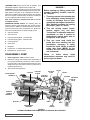
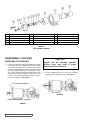
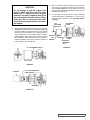
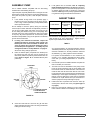
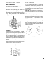
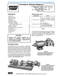
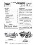
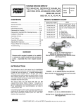
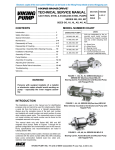
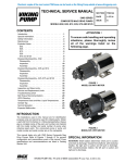
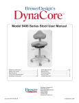
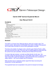
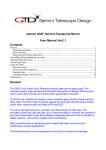
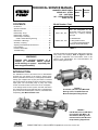
TECHNICAL SERVICE MANUAL
magnetic drive pumps
series 823 – steel
825 – cast iron
827 – stainless steel
sizes k & kk
CONTENTS
SECTION
TSM 845
PAGE
1 of 14
ISSUE
D
Model Number Chart
Introduction . . . . . . . . . . . . . . . . . . . . . . . . 1
Special Information . . . . . . . . . . . . . . . . . . . . 3
Maintenance . . . . . . . . . . . . . . . . . . . . . . . 3
Disassembly: Pump . . . . . . . . . . . . . . . . . . . 4
Disassembly: Coupling . . . . . . . . . . . . . . . . . . 6
Disassembly & Assembly
of MD-C Series Bearing Housing . . . . . . . . . . . 8
Installation of Bushings . . . . . . . . . . . . . . . . . 10
Assembly: Coupling . . . . . . . . . . . . . . . . . . 10
Adjusting Head Gasket End Clearance . . . . . . . . 11
Pump Rotation . . . . . . . . . . . . . . . . . . . . . 11
Pressure Relief Valve . . . . . . . . . . . . . . . . . 11
Troubleshooting . . . . . . . . . . . . . . . . . . . . 13
WARNING !
Persons with surgical implants of a
metallic or electronic nature should
avoid working on pump – especially the
inner magnet assembly.
UNMOUNTED
UNITS
K-823 , 825 , 827
Units are designated by the
unmounted pump model numbers
followed by a letter(s) indicating
drive style.
KK823 , 825 , 827
B = Bracket Mount
R = Viking Reducer Drive
P = Commercial Speed Reducer
(Example: KK-827-MD-C80R)
TABLE 1
This manual deals only with Series 823, 825 and 827 magnetic
drive pumps and couplings. Refer to Figures 1 thru 23
for general configuration and nomenclature used in this
manual. Pump specifications and recommendations are
listed in Catalog Section 845.
INTRODUCTION
The illustrations used in this manual are for identification
purposes only and should not be used for ordering parts.
Secure a parts list from the factory or a Viking® representative.
Always give complete name of part, part number or material
with model number and serial number of pump when ordering
repair parts. The unmounted pump or pump unit model
number and serial number can be found on the nameplate.
In the Viking® model number system, the basic size letters
are combined with the series (823, 825, 827), indicating basic
pump construction material (steel, cast iron, or stainless steel
respectively). See Model Number Chart.
figure 1
K & KK-827 (stainless steel) MD-C80 B
Bearing Carrier, Footed Bracket and
Mounted Pump with Flanged Ports.
figure 2
K & KK-825 (cast iron) MD-C80 R
Unit complete with Motor, “B”
Gear Reducer, Bearing Carrier
mounted to base with Mounted
Pump featuring Tapped Ports.
VIKING PUMP, INC. • A Unit of IDEX Corporation • Cedar Falls, IA 50613 USA
SAFETY INFORMATION
INCORRECT INSTALLATION, OPERATION OR MAINTENANCE OF EQUIPMENT MAY CAUSE SEVERE
PERSONAL INJURY OR DEATH AND/OR EQUIPMENT DAMAGE AND MAY INVALIDATE THE WARRANTY.
This information must be read fully before beginning installation, operation or maintenance and must be
kept with the pump. All installation and maintenance must be undertaken by suitably trained or qualified
persons only.
Symbol
Legend :
!
!
Danger - Failure to follow the listed
precautionary measures identified by
this symbol may result in serious injury
or death.
DO NOT OPERATE PUMP IF:
– The front cover is not installed correctly.
WARNING
WARNING
– Any guards are missing or incorrectly installed.
– The suction or discharge piping is not connected.
!
DO NOT place fingers, etc. into the pumping chamber
or its connection ports or into any part of the drive train
if there is ANY possibility of the pump shafts being
rotated. Severe injury will occur.
!
DO NOT exceed the pumps rated pressure, speed, and
temperature, or change the system/duty parameters
from those for which the pump was originally supplied,
without confirming its suitability for the new duty.
!
INSTALLATION AND OPERATION OF THE PUMP
MUST ALWAYS COMPLY WITH HEALTH AND
SAFETY REGULATIONS.
!
Rare earth magnets used in couplings have
extremely strong magnetic fields capable of
changing performance or damaging items such as:
Pacemakers, Metal Implants, Watches, Computers
& Disks, and Credit Cards
WARNING
WARNING
WARNING
!
!
!
!
A device must be incorporated into the pump, system,
or drive to prevent the pump exceeding its stated duty
pressure. It must be suitable for both directions of
pump rotation where applicable. Do not allow pump
to operate with a closed/blocked discharge unless a
pressure relief device is incorporated. If an integral
relief valve is incorporated into the pump, do not allow
re-circulation through the relief valve for extended
periods.
The mounting of the pump or pump unit should be
solid and stable. Pump orientation must be considered
in relation to drainage requirements. Once mounted,
shaft drive elements must be checked for correct
alignment. Rotate pump shaft by at least one full
revolution to ensure smoothness of operation.
Incorrect alignment will produce excessive loadings
and will create high temperatures and increased noise
emissions. Do not use any drive arrangements which
cause sideloading of the drive shaft.
The installation must allow safe routine maintenance
and inspection (to check for leakage, monitor
pressures, etc) and provide adequate ventilation
necessary to prevent overheating.
ISSUE
D
PAGE OF 14
DO NOT INSTALL THE PUMP INTO A SYSTEM
WHERE IT WILL RUN DRY (I.E. WITHOUT A
SUPPLY OF PUMPED MEDIA).
Pressure gauges/sensors are recommended, next
to the pump suction and discharge connections to
monitor pressures.
Caution must be taken when lifting the pump. Suitable
lifting devices should be used as appropriate. Lifting
eyes installed on the pump must only be used to lift
the pump, not pump with drive and/or baseplate. If
pump is baseplate mounted, the base plate must be
used for all lifting purposes. If slings are used for lifting,
they must be safely and securely attached. For weights
of bare shaft pumps refer to catalog.
DO NOT attempt any maintenance or disassembly of
the pump or pump unit without first ensuring that :
– The pump is fully isolated from the power source
(electric, hydraulic, pneumatic).
– The pumping chamber, relief valve and any
shaft seal support system are depressurized and
purged.
– Any temperature control devices (jackets, heattracing, etc) are fully isolated, that they are
depressurized and purged, and components are
allowed to reach a safe handling temperature.
!
!
!
!
SECTION TSM 845
Before operating the pump, be sure that it and all
parts of the system to which it is connected are clean
and free from debris and that all valves in the suction
and discharge pipelines are fully opened. Ensure that
all piping connecting to the pump is fully supported
and correctly aligned with its relevant connections.
Misalignment and/or excess loads will cause severe
pump damage.
Be sure that pump rotation is correct for the desired
direction of flow.
Completely assembled magnetic couplings will
not affect items listed above - only disassembled
components.
There are no known harmful effects of these
magnetic fields on the human body.
Warning - Safety instructions which
shall be considered for reasons of safe
operation of the pump or pump unit and/
or protection of the pump or pump unit
itself are marked by this symbol.
DO NOT attempt to dismantle a pressure relief valve
which has not had the spring pressure relieved or is
mounted on a pump that is operating. Serious personal
injury or death and/or pump damage may occur.
DO NOT loosen or undo the front cover, any
connections to the pump, shaft seal housings,
temperature control devices, or other components,
until sure that such action will not allow the unsafe
escape of any pressurized media.
Pumps and/or drives can produce sound power levels
exceeding 85 dB(A) under certain operating conditions.
When necessary, personal protection against noise
must be taken.
Avoid any contact with hot parts of pumps and/or
drives which may cause injury. Certain operating
conditions, temperature control devices (jackets, heattracing, etc.), bad installation, or poor maintenance
can all promote high temperatures on pumps and/or
drives.
SPECIAL INFORMATION
DISCHARGE
DANGER !
Before opening any Viking pump liquid
chamber (pumping chamber, reservoir,
etc.) Be sure:
1. That any pressure in the chamber has
been completely vented through the
suction or discharge lines or other
appropriate openings or connections.
(See detailed procedure for venting
the pumps, pages 4, 5 and 6).
SUCTION
2. That the driving means (motor,
turbine, engine, etc.) has been
“locked out” or made otherwise nonoperational so that it cannot be
inadvertently started while work is
being done on the pump.
3. That you know what liquid the
pump has been handling and the
precautions necessary to safely
handle the liquid. Obtain a material
safety data sheet (MSDS) for the
liquid to be sure these precautions
are understood.
Failure
to
follow
above
listed
precautionary measures may result in
serious injury or death.
ROTATION: Viking Mag-Drive® pumps are designed to run
in the direction indicated on the nameplate only. If rotation
must be reversed, see “Pump Rotation” on page 10.
PRESSURE RELIEF VALVES:
1. Relief valves are mounted on the head of K and KK
size pumps. Relief Valves are not available on jacketed
heads.
2. If a Relief Valve is not furnished on the pump, some
means of over protection such as an in-line relief valve
should be provided. Do not rely on magnets decoupling
for protection from over pressure. This may result in
damage to magnets, pump or other equipment.
3. Relief valve adjusting screw cap must always point
towards suction side of pump. If pump rotation is
reversed, remove pressure relief valve and turn end for
end (See “Pump Rotation” on page 10 for additional
steps required for proper operation). See Figure 3.
4. Pressure relief valves cannot be used to control pump
flow or regulate discharge pressure.
RELIEF VALVE ADJUSTING SCREW CAP
Figure 3
MAINTENANCE
CAUTION !
Rare earth magnets used in these
couplings
have
extremely
strong
magnetic fields capable of changing the
performance or damaging items such as
the following:
Pacemakers
Metal Implants
Watches
Computers & discs
Credit Cards
Completely
assembled
magnetic
couplings will not affect items listed
above.
Altered performance or damage can
occur only when the coupling halves are
separated.
There are no known harmful effects of
these magnetic fields on the human
body.
Series 823, 825 and 827 pumps are designed for long,
trouble-free service life under a wide variety of application
conditions with a minimum of maintenance. The points listed
below will help provide long service life.
For additional information on pressure relief valves, refer
to Technical Service Manual TSM000 and Engineering
Service Bulletin ESB-31.
SECTION TSM 845
ISSUE
D
PAGE OF 14
CLEANING PUMP: Keep pump as clean as possible. This
will facilitate inspection, adjustment and repair work.
STORAGE: If pump and coupling are to be stored, drain pump
and pour non-detergent SAE 30 weight oil into the pump port.
Apply grease to the pump or the coupling shaft extension, if
present or accessible. Viking suggests rotating pump shaft by
hand one complete revolution every 30 days to circulate the
oil. The coupling should be stored in a dry area.
Note: if the liquid to be pumped reacts with oil, use an
acceptable alternate.
SUGGESTED REPAIR TOOLS: The following tools are
required to properly repair Series 823, 825, and 827 pumps.
These tools are in addition to standard mechanics’ tools such
as open-end wrenches, pliers, screwdrivers, etc. Most of the
items can be obtained from an industrial supply house.
1. Soft face hammer
2. Allen wrenches
3. External Snap ring pliers - 2-810-029-375
4. Internal Snap ring pliers - 2-810-047-999
Before opening any Viking pump liquid
chamber (pumping chamber, reservoir,
etc.) Be sure:
1. That any pressure in the chamber has
been completely vented through the
suction or discharge lines or other
appropriate openings or connections.
(See detailed procedure for venting
the pumps, pages 4, 5 and 6).
2. That the driving means (motor,
turbine, engine, etc.) has been
“locked out” or otherwise made nonoperational so that it cannot be
inadvertently started while work is
being done on the pump.
3. That you know what liquid the
pump has been handling and the
precautions necessary to safely
handle the liquid. Obtain a material
safety data sheet (MSDS) for the
liquid to be sure these precautions
are understood.
5. Feeler gauge set
6. Arbor Press
7. Brass Bar
8. Hand Knobs - 2-790-046-999 (2 Required)
9. Standard 5/16” 12 point socket
DISASSEMBLY: PUMP
1. Refer to Figures 4, 5 & 6 for names of parts.
2. Mark head, casing, and bracket before disassembly to
insure proper reassembly. The idler pin, which is offset in
the pump head, must be positioned toward and an equal
distance from port connections to allow for proper flow of
liquid through the pump.
3.
DANGER !
Failure
to
follow
above
listed
precautionary measures may result in
serious injury or death.
Remove the head capscrews.
CANISTER
OUTER MAGNET
ASSEMBLY
BALANCE
PLATE
CANISTER
O-RINGS
ROTOR
CASING
BRACKET
BUSHINGS
IDLER PIN
BEARING
CARRIER
ASSEMBLY
BRACKET
BRACKET
IDLER
INNER MAGNET
ASSEMBLY
HEAD
HEAD
GASKET
figure 4
cutaway view mag-drive pump, model kk-825 md-80 b illustrated
SECTION TSM 845
ISSUE
D
PAGE OF 14
PRESSURE
RELIEF
VALVE
4. Remove head from pump. Do not allow idler to fall from
idler pin. Tilt top of head back when removing to prevent
this. Avoid damaging head gasket set, all gaskets are
required to maintain end clearance.
5. Remove idler and bushing assembly. If idler bushing
needs replacing, see “Installation of Bushings”
page 9. If further disassembly is required pump must
be separated from coupling. Refer to “Disassembly:
Coupling,” on page 5, before proceeding with Step 6.
6. After inner magnet is removed then remove key and
external retaining ring from the shaft. Rotor and shaft
may now be extracted by tapping on end of the shaft
with a soft face hammer (if a soft faced hammer is
unavailable a regular hammer may be used with a piece
of hardwood).
ITEM
NAME OF PART
ITEM
7. Mark the location and orientation of the Balance plate
before removing by pulling out. (The balance plate may
not be removable in the 825 series).
The casing should be examined for wear, particularly in the
area between ports. All parts should be checked for wear
before pump is assembled.
When making major repairs, such as replacing a rotor and
shaft, it is advisable to also install a new head and idler pin,
idler and bushing, and casing bushings. See “Installation of
Bushings” on page 9.
Clean all parts thoroughly and examine for wear or damage.
Check bushings, idler pin and balance plate; replace if
necessary.
NAME OF PART
ITEM
NAME OF PART
1
Bracket Gasket - Primary
10
Casing
19
Head Gasket
2
Bracket Gasket
11
Capscrew for Inner Magnet
20
Idler Pin
3
Orifice
12
Lockwasher
21
Head & Pin
4
Bracket
13
Washer
22
Pipe Plug
5
Capscrews for Casing
14
External Retaining Ring
23
Capscrews for Head
6
Casing Gasket
15
Key
24
Gaskets for Relief Valve
7
Bracket Bushings
16
Rotor & Shaft
25
Relief Valve
8
Balance Plate (Maybe Not in 825)
17
Idler Bushing
26
Capscrews for Relief Valve
9
Pipe Plugs
18
Idler & Bushing
FIGURE 5
K & KK Mag Drive Pump
SECTION TSM 845
ISSUE
D
PAGE OF 14
ITEM
NAME OF PART
ITEM
NAME OF PART
ITEM
NAME OF PART
1
Capscrews
5
Ball Bearing (2 Req’d)
9
Bracket
2
External Snap Ring
6
Internal Snap Ring
10
Canister
3
Bearing Housing
7
Key
11
Inner Magnet Assembly
4
Bearing Spacer
8
Outer Mag Assembly
12
Hand Knobs
FIGURE 6
md-c series coupling
DISASSEMBLY: COUPLING
SERIES MD-C80 COUPLING
1. If unit has a spacer coupling then bracket of coupling
can stay bolted to base. Without spacer coupling, either
the reducer will need to be removed or the coupling
unbolting. Remove piping to pump, provide a minimum
of 4” of clearance beyond end of coupling shaft. Insert
(2) .5” U.N.C. handknobs which have a minimum of 4.5”
of full threads into the two tapped holes at 9 and 3.00
positions on the back of the bearing housing. Remove
the (4) .375 capscrews. See Figure 7.
CAUTION !
Magnet sets are extremely powerful.
Serious injury may result if proper
procedures are not followed.
2. Turn the handwheels evenly to back out the bearing
housing and outer magnet assembly. See Figure 8.
.375” capscrews (4 Req’d)
Figure 8
hand knobs (2 req’d) 2-790-046-999
Figure 7
SECTION TSM 845
ISSUE
D
PAGE OF 14
CAUTION !
Do not attempt to pull the magnet sets
apart by hand until the outer has been
backed off 4”. Support the outer magnet
assembly and pull completely away from
the inner magnet. Be careful when setting
down this unit to avoid tools and other
metal objects being attracted to the end of
the magnet.
3. Support pump with hoist and remove the (4) .5” capscrews.
See Figure 9. Pull the pump out of the bracket; there will
be some resistance to pull apart since the inner magnet
assembly will be attracted to the coupling bracket. If
further disassembly of the bearing carrier is required,
refer to page 7. Since there will be some liquid left in
the canister, be aware that liquid will run out when the
canister separates from the pump. Remove canister if it
has not already come off the pump.
0.5” capscrews (4 req’d)
4. Insert a brass bar through a port between two rotor teeth
and loosen the capscrew holding the inner magnet to
the shaft (See Figure 11). Do not forget, this is a very
strong magnet. If pump disassembly is required, remove
the external retaining ring.
5. Do not remove the O-ring unless it is bad, especially
if PTFE (Derivative) encapsulated. If a new O-ring is
required, follow instructions in the “Assembly: Pump”
on page 7.
secondary
o-ring
0.44”
capscrew
with hole
washer
lock
washer
inner
magnet
primary
o-ring
external
retaining
ring
figure 11
figure 9
canister
0.44” capscrew right
hand threads
brass bar
figure 10
SECTION TSM 845
ISSUE
D
PAGE OF 14
DISASSEMBLY & ASSEMBLY OF
MD-C SERIES BEARING HOUSING
PRESS
DISASSEMBLY
The bearing housing features two sealed ball bearings along
with an outer magnet assembly. If further disassembly of this
unit is required, proceed as follows:
1. Refer to Figure 12 for part identification. Cover the open
end of the outer magnet with a piece sheet metal or
cardboard. This will keep foreign material out of magnet
area. Set the assembly face down with the shaft pointing
up and remove handknobs.
2. Remove external retaining ring from shaft, place unit
into press and push out shaft as shown in Figure 13.
Support end of outer magnet to prevent it from dropping
as possibly being damaged.
3. Remove the internal retaining ring and press out
bearings.
BEARING
HOUSING
INTERNAL
RETAINING
RING
SHEET METAL
COVER 6.50”
SQUARE
figure 13
SPACER
EXTERNAL
RETAINING
RING
PRESS
BALL BEARINGS
figure 12
ASSEMBLY
1. Place (1) bearing into housing bore. Gently tap or press
into bore. Position spacer in bore and insert second
bearing. Press down until bearings bottom out. Install
internal retaining ring into bearing housing.
2. Slide shaft of outer magnet assembly into bearing until
it meets resistance. Set upright in press (See Figure
14) and place a spacer on the end of housing such as
3” NPT coupling and press housing down until bearing
bottoms out on shaft shoulder. Install external retaining
ring on shaft of outer magnet assembly.
figure 14
SECTION TSM 845
ISSUE
D
PAGE OF 14
SPACER
(3”NPT
COUPLING)
ASSEMBLY: PUMP
Use a suitable lubricant compatible with the fluid being
handled when reassembling the pump.
Inspect all parts, especially drilled holes in casing for the suck
back system to make sure they are not plugged. Replace any
worn parts and polish any burrs; clean all parts; assemble
pump.
1. If the canister O-rings need to be replaced, apply a
lubricant to the O-ring and place into the O-ring groove.
If the O-ring is PTFE (derivative) encapsulated, follow
these special instructions.
Do not attempt to reuse the primary O-ring if it has been
removed (and is PTFE derivative encapsulated). Immerse a
new O-ring in boiling water and stretch out O-ring so it will
fit onto casing hub without forcing over a sharp edge. Run
hot water over O-ring until it shrinks down tight onto the pilot
of the pump. Dry with compressed air. The secondary PTFE
derivative encapsulated O-ring can be placed in the bracket
groove with some lubricant.
2. If casing was removed from bracket, inspect flat
gasket and replace if necessary. Install casing onto
bracket pilot in the same orientation as before. This
series of pumps does not allow rotating the casing
to alternate port configurations – to modify the port
arrangement, Refer to “Pump Rotation” on page 10.
Secure the casing with (8) capscrews.
3. Place the balance plate (if separate from bracket) into
the casing bore (this step may not be required in the
825 series). Make sure plate is positioned the same as
before. Refer to Figure 15 for standard balance plate
positioning.
GASKET TABLE
PUMP MODEL
NORMAL END
CLEARANCE
(iNCH.)
SET OF GASKETS
CONSISTS OF THE
FOLLOWING
K & KK 825
.008
K & KK 823, 827
.010
(1) .015
(2) .007
(3) .005
End clearances are adequate for viscosity’s up to 750 SSU
(SAE 20-lube oil at room temperature). Higher viscosity
liquids require additional end clearances.
TABLE 2
As a general guideline, for viscosity’s between 750 and
7500 SSU (heavier lube oils) double the amount of end
clearance indicated, for viscosity’s between 7500 and
25,000 SSU (e.g., resins) triple the amount indicated.
For specific recommendations for end clearances for
viscosity or for operating temperatures above 225ºF,
check with your Viking Representative or consult the
factory.
6. Coat the idler pin with a suitable lubricant and place the
idler on the idler pin in the head.
DISCHARGE
PORT
SUCTION
PORT
5. If old gaskets are not reusable, refer to “Adjusting
Head Gasket End Clearance” on page 10. Otherwise,
place the head gaskets on the head. The proper amount
of gaskets should be used to provide the correct end
clearance. Table 2 gives the quantity of gaskets available
in a gasket set along with standard end clearance.
GROOVE
7. The head can now be assembled on the pump. Tilt the
top of the pump head away from the pump slightly until
the crescent enters the inside diameter of the rotor and
rotate the idler until its teeth mesh with the rotor teeth.
Pump head and casing should have been marked before
disassembly to insure proper reassembly. If not, be sure
idler pin, which is offset in the pump head, is positioned
toward and an equal distance from port connections to
allow for proper flow of liquid through the pump.
8. Install relief valve if provided and removed. Valve cap
should point to Suction side of the pump (See Figure 3
on page 2).
STANDARD POSITION
CW ROTATION AS
VIEWED FROM HEAD
9. Place key and external retaining ring onto shaft then
follow instruction listed for assembling to the coupling.
figure 15
4. Clean rotor and shaft so it is free of dirt, grit and other
debris and apply lubricant. Push into casing and bracket
bushings as far as it will go.
SECTION TSM 845
ISSUE
D
PAGE OF 14
INSTALLATION OF BUSHINGS
CARBON GRAPHITE:
When installing carbon graphite bushings, extreme care must
be taken to prevent breaking. Carbon graphite is a brittle
material and easily cracked. If cracked, the bushing will
quickly disintegrate. Using a lubricant and adding a chamfer
on the bushing and the mating part will help in installation.
The additional precautions listed below must be followed for
proper installation:
When removing old bracket bushings, mark location of
lubrication groove.
2. Inspect canister O-ring for signs of wear and replace if
necessary. Slide canister over inner magnet and press
over O-ring until canister meets the pump mounting
flange.
3. Support the pump from overhead and secure coupling
bracket to avoid tipping when pump is attached. Using
the canister as a guide, slide the pump assembly up
to the coupling bracket through the smaller opening.
Secure with the four 0.5” capscrews. See Figure 17.
pump - bracket capscrews
(4 required)
1. An arbor press must be used for installation.
2. Be certain bushing is started straight.
3. Do not stop pressing operation until bushing is in proper
position, starting and stopping will result in a cracked
bushing.
4. Check bushing for cracks after installation.
SILICON CARBIDE
When installing Silicon Carbide bushings into a metal part
the mating part must be heated to 600° F (preferable in an
oven). The bushing must be put into the proper position
quickly before the mating part cools down and the bushing
heats up. Failure to follow this procedure will result in cracked
bushings.
ASSEMBLY COUPLING:
SERIES MD-C80 COUPLING
DANGER !
figure 17
4. The outer magnet should be installed into the bearing
housing, if not refer to Disassembly & Assembly of
Bearing Housing. Install hand knobs so that 4” of threads
are projecting below housing. Support bearing housing
from overhead and gently position magnet over canister
so the magnet assemblies start to engage. Evenly
back out the hand knobs. See Figure 18. the bearing
housing move toward the bracket as the hand knobs are
removed.
Follow these directions exactly to avoid
injury to self or damage to pumping unit.
Be careful to keep inner & outer magnets
at least (1) foot apart until step 3. Do not
engage magnets in any other fashion.
1. Inspect magnets for any steel objects attached to the
magnets. Remove any foreign material. Place external
retaining ring and key on pump shaft. Slide inner magnet
assembly onto shaft so it butts against retaining ring.
Install washer, lock washer and capscrew to secure
magnet (See Figure 16). Insert a brass bar through a
port between two rotor teeth and tighten capscrew.
canister
0.44”
capscrew
with hole
lock
washer
washer
secondary o-ring
inner
magnet
ISSUE
D
5. Install the (4) 0.375” capscrews. Turn the output shaft
over by hand to make sure the pump rotates freely. See
Figure 19).
0.375” capscrews
(4 required)
primary o-ring
external
retaining
ring
figure 19
figure 16
SECTION TSM 845
figure 18
PAGE 10 OF 14
ADJUSTING HEAD GASKET
END CLEARANCE
Use either of the following procedures to properly adjust the
end clearance when replacing gaskets:
PROCEDURE A:
With balance plate in position, slide rotor and shaft into
casing. Insert a feeler gage of the proper thickness into the
port and between two rotor teeth (See Figure 20 on page
10). Install one 0.015” and one 0.007” gasket onto head.
With the idler on the idler pin, place the head into the pump
casing. With the capscrews tight, the feeler gage should fit
snugly, otherwise gaskets should be added or removed until
the proper clearance is attained.
PUMP ROTATION
The pump is designed to take fluid from the discharge side
of the pump and channel it down the idler pin into the shaft
and out into the canister through the capscrew which secures
the inner magnet. The fluid is returned through a hole in
the casing back to the suction side of the pump. There are
generally three parts which may need replacing or adjusting
to change rotation.
HEAD & PIN – Hole should be from the discharge side of
head to the pin and a pipe plug is placed in the tapped hole
on the suction side of the head. To change rotation, move the
plug to the opposite side of the head.
BALANCE PLATE – If the plate is separate from the bracket
and looks like the Style A in Figure 22, it can be reversed. The
groove should connect the discharge port to the bushing bore.
If rotation is changed, the plate is flipped over (not rotated)
and the groove would not be visible but will still function
properly. If the plate is like Style B, it is NOT reversible and a
new plate will be required.
BRACKET – The bracket will have two holes drilled through
and tapped on one side. The discharge side of the bracket
should feature a pipe plug with a hole drilled through it. To
change rotation simply move this pipe plug to the other hole.
Contact your local Viking distributor or the factory to determine
which parts are required.
GROOVE
figure 20
PROCEDURE B:
If the pump is in line and the ports are not accessible,
remove the head and gaskets. Put the head back on (without
gaskets) and measure the gap as shown. (See Figure 21 on
page 10). After determining the gap between the head and
casing, select a combination of gaskets with approximately
25% more total thickness than the gap plus the required end
clearance. Note that the gaskets will compress when head is
tightened down. Remove the head, install all gaskets then
replace the head. Tighten the head capscrews and check
the pump clearance by making sure the pump turns freely
by hand.
STYLE A
STYLE B
figure 22
Since the pump shaft is concealed, it is best to work up the
proper end clearance because it is difficult to determine when
there is to much end clearance with this approach.
figure 21
SECTION TSM 845
ISSUE
D
PAGE 11 OF 14
PRESSURE RELIEF VALVE
DANGER !
Before opening any Viking pump liquid
chamber (pumping chamber, reservoir,
etc.) Be sure:
1. That any pressure in the chamber has
been completely vented through the
suction or discharge lines or other
appropriate openings or connections.
(See detailed procedure for venting
the pumps, pages 4, 5 and 6).
2. That the driving means (motor,
turbine, engine, etc.) has been
“locked out” or made otherwise nonoperational so that it cannot be
inadvertently started while work is
being done on the pump.
3. That you know what liquid the
pump has been handling and the
precautions necessary to safely
handle the liquid. Obtain a material
safety data sheet (MSDS) for the
liquid to be sure these precautions
are understood.
Failure
to
follow
above
listed
precautionary measures may result in
serious injury or death.
ASSEMBLY: RELIEF VALVE
Reverse procedures outlined under Disassembly. If valve
is removed for repairs, be sure to replace in same position.
Relief valve adjusting screw cap must always point towards
suction side of pump. If pump rotation is reversed, remove
relief valve and turn end for end. Refer to Figure 3, page 2.
PRESSURE ADJUSTMENT
If a new spring is installed or if pressure setting of pressure
relief valve is to be changed from that which the factory has
set, the following instructions must be carefully followed.
1. Carefully remove valve cap, which covers adjusting
screw.
Loosen locknut, which locks adjusting screw so pressure
setting will not change during operation of pump.
2. Install a pressure gauge in discharge line for actual
adjustment operation.
3. Turn adjusting screw in to increase pressure and out to
decrease pressure.
4. With discharge line closed at a point beyond pressure
gauge, gauge will show maximum pressure valve will
allow while pump is in operation.
IMPORTANT
In ordering parts for pressure relief valve, always give
model number and serial number of pump as it appears on
nameplate and name of part wanted. When ordering springs,
be sure to give pressure setting desired.
DISASSEMBLY: RELIEF VALVE
Mark valve and head before disassembly to insure proper
reassembly.
1. Remove valve cap.
2. Measure and record length of extension of adjusting
screw. Refer to “A” on Figure 23.
3. Loosen locknut and back out adjusting screw until spring
pressure is released.
4. Remove bonnet, spring guide, spring and poppet from
valve body. Clean and inspect all parts for wear or
damage and replace as necessary.
VALVE - AS, AK AND AL SIZES
VALVE - LIST OF PARTS
1. Valve Cap
6. Valve Body
2. Adjusting Screw
7. Valve Spring
Before starting pump, be sure all drive
equipment guards are in place.
3. Lock Nut
8. Poppet
Failure to properly mount guards may
result in serious injury or death.
5. Bonnet
DANGER !
SECTION TSM 845
ISSUE
D
PAGE 12 OF 14
4. Spring Guide
9. Cap Gasket
10.
FIGURE 23
Bonnet Gasket
TROUBLESHOOTING
Some of the following may help pinpoint the problem:
PUMP INFORMATION
Pump Model Number:
Pump does not pump:
►
►
►
►
►
►
►
►
►
►
Lost its prime from air lead or low level in tank.
Suction lift too high.
Rotating in wrong direction.
Strainer clogged.
Bypass valve open, pressure relief valve set too low or
pressure relief valve poppet stuck open.
Improper end clearance.
Pump worn out.
Any changes in liquid, system or operation that would
influence pump or coupling performance, e.g. new liquid,
additional lines or process changes.
Temperature changes either in the liquid or the
environment.
Magnetic coupling is decoupling. Change in application
(temperature, pressure, viscosity,’ etc.) may require
torque beyond coupling capabilities.
Serial Number:
Date Received:
Date Installed:
Distributor:
Contact Person:
Pump starts, then loses its prime:
► Supply tank empty.
► Liquid vaporizing in the suction line.
► Air leak or air pocket in the suction line.
Phone:
Pump is noisy:
Fax:
► Pump is being starved (heavy liquid cannot get to pump
fast enough). Increase suction pipe size, reduce length
or slow down pump.
► Pump is cavitating (liquid vaporizing in suction line).
Increase suction pipe size or reduce length.
► Check alignment.
► Magnetic coupling decoupled. Shut off and restart.
E-mail:
Comments:
Pump not delivering up to capacity:
► Starving or cavitating - increase suction pipe size or
reduce length.
► Strainer partially clogged.
► Air leak somewhere in suction line.
► Running too slow. Is motor the correct speed and
wired up correctly.
► Pressure relief valve set too low, tuck open or has
damaged poppet / seat.
► Bypass line around pump partially open.
► Pump worn out or too many gaskets.
Pump takes too much power (stalls motor):
►
►
►
►
Liquid more viscous than unit sized to handle.
System pressure relief valve set too high.
Coupling misaligned.
Bushings frozen up or liquid set up in coupling.
SECTION TSM 845
ISSUE
D
PAGE 13 OF 14
TECHNICAL SERVICE MANUAL
magnetic drive pumps
series 823 – steel
825 – cast iron
827 – stainless steel
sizes k & kk
SECTION
TSM 845
PAGE
14 of 14
ISSUE
D
WARRANTY
Viking warrants all products manufactured by it to
be free from defects in workmanship or material for a
period of one (1) year from date of startup, provided
that in no event shall this warranty extend more than
eighteen (18) months from the date of shipment from
Viking. If, during said warranty period, any products
sold by Viking prove to be defective in workmanship
or material under normal use and service, and if such
products are returned to Viking’s factory at Cedar Falls,
Iowa, transportation charges prepaid, and if the products
are found by Viking to be defective in workmanship
or material, they will be replaced or repaired free of
charge, FOB. Cedar Falls, Iowa.
Viking assumes no liability for consequential
damages of any kind and the purchaser by acceptance
of delivery assumes all liability for the consequences of
the use or misuse of Viking products by the purchaser,
his employees or others. Viking will assume no field
expense for service or parts unless authorized by it in
advance.
Equipment and accessories purchased by Viking
from outside sources which are incorporated into any
Viking product are warranted only to the extent of and
by the original manufacturer’s warranty or guarantee,
if any.
THIS IS VIKING’S SOLE WARRANTY AND IS IN
LIEU OF ALL OTHER WARRANTIES, EXPRESSED
OR IMPLIED, WHICH ARE HEREBY EXCLUDED,
INCLUDING IN PARTICULAR ALL WARRANTIES
OF MERCHANTABILITY OR FITNESS FOR A
PARTICULAR PURPOSE. No officer or employee of
IDEX Corporation or Viking Pump, Inc. is authorized to
alter this warranty.
VIKING PUMP, INC. • A Unit of IDEX Corporation • Cedar Falls, IA 50613 USA
© 5/2007 Viking Pump Inc.
All rights reserved