1
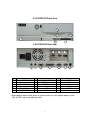
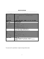
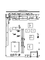
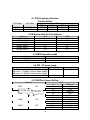
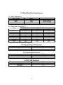
E-Pos 1000 (P3) / E-Pos Cel U s er Man u al 1 TABLE OF CONTENTS Introduction - 2 Table of Contents - 3 Location - 4 Do’s & Don’ts - 5 Accessories - 6 Input /Output Function - 7 Specifications - 9 Jumper Settings - 10 2 LOCATIONS Corporate Head Quarters Middle East E-PoS International LLC P.O.Box 12608 Dubai, UAE Tel: +9714-3523288 / 3512861 Fax: +9714-3513396 Email: [email protected] South East Asia Head Quarters South Asia East E-PoS International Nasik-Pune Road Ayodhya Nagri Nasik, Maharasthra India Tel: +91-253-2411806 Fax: +91-252-2415295 Email: [email protected] 3 DO’S & DON’TS (Integrated circuits on All E-PoS System boards are sensitive to static electricity. To avoid damaging any Components on the computer board, before getting started, read these following precautions and other instructions and save them for later reference). i. ii. iii. iv. v. vi. vii. viii. ix. x. xi. xii. Do not remove the computer from the anti-static Packaging until you are ready for installation. Make sure the voltage of the power source is correct before connecting the computer to the power outlet, (110~220 volts). Connect Rubber Legs provided to avoid damaging Cabinet Cover and Door, (where provided). Do not change any Hardware Devices online when System or the device is on and running, because the sudden surge of power may ruin any sensitive components. Also make sure the computer is properly grounded. Turn off the computer before cleaning. Always clean with a damp or dry cloth only. Do not spray any liquid cleaner on screen directly. The power outlet socket used to plug in the computer power cord must be located near the system and easily accessible. Do not use outlets on the same circuit of the system that regularly switch on and off. If the computer is sharing an extension cord with other devices, make sure the total ampere rating of the devices plugged into the extension cord does not exceed the cord’s ampere rating. Do not expose the power cord, extension cord and power outlet to moisture. The openings on the computer enclosure are for the cabin ventilation to prevent the computer from overheating. DO NOT COVER THE OPENINGS. Do not connect any devices to Powered COM Ports (5V/12V), other then the devices that take power from Powered COM Ports to avoid damaging the Device. Any Hardware upgrades or changes to be made are to be informed, and do not tamper with Serial Nos. and Warranty Seals, to avoid Warranty Void. xiii. If the computer is not equipped with an operating system. An operating system must be loaded first before installing any software into the computer. If the computer is equipped with a touch panel, avoid using sharp objects to operate the xiv. touch panel. Scratches on the touch panel may cause mal-calibration or non-function to the panel. The LCD panel display is not subject to shock or vibration. When assembling the computer, make sure it is securely installed. xv. Choose an Ideal dust free location and reliable surface for the System with proper ventilations. 4 ACCESSORIES 1. Warranty Card. 2. Power Cable. 3. Driver Bank CD. 4. Keys. 5. CD – ROM (Optional only for 1000 (P3) series). The following drivers in the folders of Driver Bank are necessary for driver installation. Folder Common B63 Driver CDROMDrv LAN_drive VGA Function CDROM driver installation (for DOS) LAN driver installation VGA driver installation 5 INPUT / OUTPUT FUNCTIONS 2.1 E-POS Cel Front View 2 3 5 1 4 6 2.2 E-POS Cel Rear View 16 7 # 1 2 3 4 5 6 8 Function Power/HDD Indicator Key Hole Power Button USB1/2 Floppy Disc Drive Compact Flash 9 10 # 7 8 9 10 11 12 Function PS/2 Keyboard PS/2 Mouse VGA LPT COM2 COM1 6 15 11 14 12 # 13 14 15 16 13 Function LAN DIO COM4 COM3 2.3 E-POS1000 Front View 3 4 5 1 6 7 2.4 E-POS1000 Rear View 17 8 # 1 2 3 4 5 6 Function Power/HDD Indicator Key Hole CD-ROM Drive Floppy Disc Drive Power Button USB1/USB2 9 # 7 8 9 10 11 12 10 11 Function Compact Flash PS/2 Keyboard PS/2 Mouse VGA LPT COM2 16 12 # 13 14 15 16 17 15 13 14 Function COM1 LAN DIO COM4 COM3 Before plug-in power cord & power on, please make sure your regional power system 110V or 220V, and set up right dip switch. 7 SPECIFICATIONS ________________________________________________________ MODEL B/M CPU Co-processor Internal Cache External Cache System RAM BIOS Core Logic Video Display Video RAM Video Display port HDD Controller FDD Controller I/O Port Keyboard & Mouse LAN USB ROM disk Compact Flash Expansion Slot Power Supply 1631/4631 B63 Intel socket 370 CPUs Celeron /PIII PPGA/FC-PGA Built-in CPU Built-in CPU Built-in CPU 2x 168pin DIMM sockets, support 16 / 32 / 64 / 128 /256 MB AWARD PnP BIOS Intel FW82443BX S3 Trio 3D AGP 4MB SGRAM 15-pin D-SUB female VGA x 1 40-pin 2.54 pitch IDE pin-header x 1 SMSC37C602, 34-pin 2.54mm pitch pin-header x 1 9-pin D-SUB RS232 FIFO Serial x 2 10-pin header support COM3/COM4 x 2 25-pin D-SUB Parallel (SPP/EPP/ECP) x 1 PS2 Keyboard x 1, Mouse x 1 Optional LAN Rising Card USB x 2 Disk On Chip Socket supported Compact Flash Socket Supported 1 EISA Bus Slot for system expansion slot used Internal AT -FT-8075 75W (5V/8.5A, 12V/2.4A, -12V/0.3A, ) -Optional FT-8075E 1202 ((5V/6A, 12V/2A, -12V/0.3A, 24V/2A, ) The content of this specification is subject to change without notice. 8 7 JUMPER SETTINGS 56 8 9 U R C J # & $ % PJQ T J :"; FGI ~ <>= FGH FJG"K PQMR>S ?A@ MC F"H FGMLCL ?CB M> M N"O D E ÜÝCÞß ÜJÝCÞMà ,- mn kl ij PQMRCV ¡ ¢ ¥¦ h "! § ' ¬ PCR"W C°C° ² ./ 23 £¤ êCëì « « Ú óó Û ÜÞá kl h âãäæå"çéè & § ' vCzt vCz>y Û £ ' _ î ð ð ñ ï + ]\ ^ + \ * Z[ Ù Ú Ô ÕÖC× Ø º¼» ¶·¸ ¹ © ) ³ ¾ s tu J oqpMr ´ ½ ´ © µ ¥ ¿ º ÃJÄMÅ ÆJÇ ÈÊÉËÌÎÍÏ>ÐÑÓÒ mn v wuMy vJwux  ÀÁ ó¼ô ª êCëÊí © ©± ij b 4 © "®¯ ¨ ( ª `a 01 XY î ðò ñ ï {J| } 9 cJdeAf cdMeCg 4.1 CPU Frequency Selection *Factory Default CPU Clock PCI Clock 100.3MHz 66.8MHz 33.43MHz 33.40MHz FS0 1-3 1-3 JP30 FS1 7-9 7-9 FS2 2-4 4-6 4.2 M-System Disk On Chip Address Address *0C800-0C9FF 0CC00 - 0CDFF 0D000 - 0D1FF 0D400 - 0D5FF 0D800 - 0D9FF 0DC00 - 0DDFF JP19 1-2 3-4 1-2 3-4 1-2 3-4 4.3 CMOS Operation mode Function *CMOS Normal CMOS Reset JP18 Close J3 1-2 Open 2-3 4.5 COM Port Jumper Setting COM Port COM1 SYSTEM FAN COM2 1-2 3-4 5-6 1-2 3-4 5-6 1-2 3-4 5-6 1-2 3-4 5-6 JP4 CPU FAN JP3 COM3 JP9 COM4 JP5 10 JP20 1-2 1-2 3-4 3-4 5-6 5-6 J12 2-3 1-2 4.4 ATX / AT power mode Function AT power supply 4000 series : FT-8050 AT Internal Power Supply 1000 series: FT-8075 AT Internal Power Supply ATX power supply FS3 10-12 10-12 Pin 1 *Data Line +5V +12V *Data Line +5V +12V *Data Line +5V +12V *Data Line +5V +12V 4.6 Digital I/O (4 Output & 4 Input): J11 This main board provides the basic digital I/O signal Controller. User can develop the program and extra controller to open and detect the cash drawer that based on the digital 4.6.1 I/O function on this main board. Pin Assignment 1 GND 2 VDC +12V 3 IN 0 4 Out 0 5 IN 1 ý ÷ ù ü Assignment Out 1 IN 2 Out 2 IN 3 Out 3 û þ ÿ Pin 6 7 8 9 10 ú õ ö ø ! "#$% 4.6.2 Digital output programming Output Address Out 0 206 Out 1 206 Out 2 206 Out 3 206 The output signal has to be TTL compatible. Bit 0 1 2 3 4.6.3 Digital input programming Input Address IN 0 206 IN 1 206 IN 2 206 IN 3 206 The input signal has to be TTL compatible. Bit 0 1 2 3 11 4.7 Watch Dog Time Programming 4.7.1 Watch Dog Address: Input / Output Output Input Input Address 205H 205H 204H 4.7.2 Watch Dog Time Setting: JP1 Time 1-2 0.1 sec ON 0.5 sec ON 1.0 sec ON *1.6 sec ON 10 sec OFF 1 min OFF 10 min OFF 1hr OFF Watch Dog ON Watch Dog WDI Watch Dog OFF JP1 3-4 ON ON OFF OFF ON ON OFF OFF 5-6 ON OFF ON OFF ON OFF ON OFF 4.8 Compact Flash CS Selection Function *Master Slave Function *Serial Keyboard Function *User 5VSB User 3VSB JP23 OFF ON 4.9 Card Reader Selection JP32 1-2, 3-4 ON 1-2, 3-4 OFF 4.10 PCI VSB Selection 12 JP31 2-3 1-2 ________________________________________________________________________ E-Pos InternationalL.L.C,P.O .Box N o.12608,D ubai,U .A .E, Tel.N o.(+9714) 3523288,Fax.N o.(+9714) 3513396, E-M ail:eposintl@ em irates.net.ae 13