1
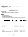
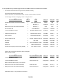
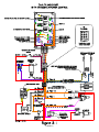
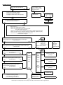
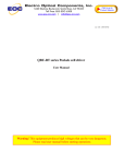
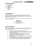
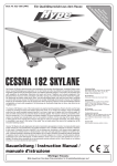
DOC # DOCSST-D 08/16/99
Wired Rite Systems 5793 Suite A, Skylane Blvd., Windsor Ca. 95492
Phone: (800) 538-7483 Or (707) 838-1122 Fax: (800) 525-7483
WEB: http://www.wiredrite.com
E-MAIL: [email protected]
5793 Suite A Skylane Blvd., Windsor, CA 95492
(800) 538-7483 (707) 838-1122 Fax (707) 838-1050
INSTALLATION OF WIRED RITE SYSTEMS SST DUAL PLUNGER ENGINE CONTROLLER
WITH EMERGENCY POWER CONTROL
HARDWARE MOUNTING:
For maximum weatherproofing mount the SST enclosure with the wire harness pointing down.
CONNECTIONS:
When installing an SST in a WRS Integrated Power System, plug the 12 pin connector, which is at the end of the SST pigtail,
into J4 of the Power Distribution Center.
Unless specified, the SST is wired as a "Negative trigger".
A Negative trigger is defined as, supplying the negative side of 12VDC (or ground) to energize a device and is configured as follows:
From
SST Circuit Board Nomenclature
Thru
J4 Pin #
To
Vehicle
Wire Color
Wire Label
AWG
IGNITION SPLICE (GAS) 12 VDC INPUT (DIESEL)
1
"KEY" SIDE OF SPLICE
Orange
IGN
14
+12V
2
BATTERY (+)
Pink/Green
SST (+)
16
GND (NOTE: DO NOT USE CHASSIS GROUND)
3
BATTERY (-)
White
NEG
16
EXT. OUTPUTS, NO
4
AUX PUMP RELAY
Purple/Green
E.POWER
14
12 VDC SYSTEM INPUT START
5
"MASTER" ENABLE SWITCH
Red/White
MASTER
14
START/STOP INPUTS, NEG
6
BUCKET START SWITCH
White/Blue
START (-)
16
FAULT OUTPUT
7
DASH INDICATOR LIGHT
Gray/Purple
FAULT
16
THROTTLE INPUTS, NEG
8
BUCKET THROTTLE SWITCH
White/Yellow
THROTTLE (-)
16
NOT USED
9
NOT USED
NOT USED
NOT USED
16
STARTER
10
OUTPUT FROM KEY "START"
Orange/Black
STARTER
14
THROTTLE
11
THROTTLE SOLENOID
Orange/Brown
THROTTLE
16
IGNITION SPLICE (GAS) FUEL SHUTOFF (DIESEL)
12
"COIL" SIDE OF SPLICE
Orange/Red
FUEL SOL
14
PAGE 1
For an application using a "Positive trigger" for both the "throttle and start", the connections are as follows:
*
The asterisk to the left indicates a change from factory default is necessary.
These changes are all internal changes to SST.
Be sure to disconnect the positive battery terminal, or unplug J4 before making any changes.
A Positive trigger is defined as: supplying +12VDC to energize a device.
From
SST Circuit Board Nomenclature
*
*
Thru
J4 Pin #
To
Vehicle
Wire Color
Wire Label
AWG
IGNITION SPLICE (GAS) 12 VDC INPUT (DIESEL)
1
"KEY" SIDE OF SPLICE
Orange
IGN
14
+12V
2
BATTERY (+)
Pink/Green
SST (+)
16
GND (NOTE: DO NOT USE CHASSIS GROUND)
3
BATTERY (-)
White
NEG
16
EXT. OUTPUTS, NO
4
AUX PUMP RELAY
Purple/Green
E.POWER
14
12 VDC SYSTEM INPUT START
5
"MASTER" ENABLE SWITCH
Red/White
MASTER
14
START/STOP INPUTS, POS
6
BUCKET START SWITCH
White/Blue
START (-)
16
FAULT OUTPUT
7
DASH INDICATOR LIGHT
Gray/Purple
FAULT
16
THROTTLE INPUTS, POS
8
BUCKET THROTTLE SWITCH
White/Yellow
THROTTLE (-)
16
NOT USED
9
NOT USED
NOT USED
NOT USED
16
STARTER
10
OUTPUT FROM KEY "START"
Orange/Black
STARTER
14
THROTTLE
11
THROTTLE SOLENOID
Orange/Brown
THROTTLE
16
IGNITION SPLICE (GAS) FUEL SHUTOFF (DIESEL)
12
"COIL" SIDE OF SPLICE
Orange/Red
FUEL SOL
14
To
SST Circuit Board Nomenclature
Wire Color
Wire Label
AWG
Orange/Blue
START (+)
16
Orange/Yellow
THROTTLE
16
Orange/Blue
START (+)
16
Orange/Yellow
THROTTLE
16
Inside the SST box there are 2 wires which need to be changed:
Below is the factory default:
From
SST Circuit Board Nomenclature
12 VDC SYSTEM INPUT START
START INP, POS
12 VDC SYSTEM INPUT START
THROTTLE INP, POS
Below are the respective changes you need to make:
*
GND (NOTE: DO NOT USE CHASSIS GROUND)
START INP, NEG
*
GND (NOTE: DO NOT USE CHASSIS GROUND)
THROTTLE INP, NEG
Please Refer to figure 3-1 for typical electrical connections.
PAGE 2
PAGE 3
OPERATION:
After mounting, and connecting the System 21 SST to your vehicle, you should now power up the system.
When the Master Switch has been activated, the SST board will automatically perform a diagnostic check
to determine that all features are operating properly. The diagnostic check routine is completed every 250
milliseconds as long as the processor power is on.
The System 21 SST board indicates a fault, using three methods:
1) Every SST comes equipped with a fault indicator LED installed on the circuit board.
2) With the optional panel mounted display & remote test switch.
3) With the optional dash warning light.
All faults are recorded in volatile memory and can be recalled at any time by depressing the test button.
As you hold the test button the LED next to the faulted circuit will flash.
To reset the fault memory you must remove the processor power for at least 1 second.
If there are no faults in the circuits that receive power when the ignition switch is turned "ON", the
following LED's on the circuit board will be illuminated:
LED #
SST Circuit Board Nomenclature
D14
THROTTLE
D15
IGNITION SPLICE OR 12 VDC INPUT INDICATOR
D16
PWR
D18
RUN (NC)
D21
START
Please refer to figure 5-1 (page 5) for the location of the LED's on the circuit board.
EMERGENCY POWER:
To activate the emergency pump relay, wire [J4 PIN # 4 ] the following conditions must be met:
1) The SST must be in "STOP" mode.
2) From the bucket… depress the Throttle Plunger and hold for four seconds.
Emergency Power will be activated as long as the button is held down.
PAGE 4
DIAGNOSTICS:
Figure 5-1
Below is a list of the LED's and the operational / fault condition they indicate:
LED #
SST Circuit Board Nomenclature
On Indicates:
D3
FAULT OUTPUT
A fault condition exists.
D4
TEST
Comes on when you depress the board mounted push to test button.
D5
STOP
The stop relay is energized, flashes if a fault is detected in the run circuit.
D6
TO STARTER SOLENOID
The start relay is energized, flashes if a fault is detected in the start circuit.
D7
TO THROTTLE SOLENOID
The throttle relay is energized, when the engine is in run mode.
D8
START INP
A start/stop trigger signal has been applied.
D9
THROTTLE INP
A throttle trigger signal has been applied.
D14
THROTTLE
Power is being applied to the 12 VDC SYSTEM
INPUT START stud, and the start relay not is energized.
D15
IGNITION SPLICE OR 12
VDC INPUT INDICATOR
Power is being applied to the IGNITION SPLICE OR 12 VDC
INPUT (DIESEL) stud.
D16
PWR
Processor power is present at the SST.
D18
RUN (NC)
The ignition switch is on, and the stop relay is not energized.
D21
START
The Master switch is on.
PAGE 5
TROUBLE SHOOTING:
STEP 1
Check the power input LED D16
ON
OFF
Refer to figure 3-1
check for battery voltage
between processor power,
processor ground.
YES
NO
STEP 2
Prepare truck for "Aerial lift operation"
a) Engage the key to the ON position
b) Engage the master switch to the ON position
STEP 3
Are all of the following LED's illuminated:
D14, D15, D16, D18, and D21
YES
Call WRS @
1-800-538-7483
Check the 80
amp main breaker
ON
OFF
Turn on breaker
NO
Go back to step 1
STEP 4
Refer to figure 5-1
If D14 is out: Throttle breaker is tripped.
If D15 is out: Ignition splice stud is not receiving power.
The ignition breaker has tripped.
If D16 is out: 12 Volts is not being supplied to the positive or negative inputs of the board.
If D18 is out: When in the run mode, the stop relay is malfunctioning. Replace stop relay.
If D14 & D21 is out: System input stud is not receiving power.
Starter breaker has tripped.
STEP 5
Supply a signal from the bucket pressure switch to start the engine.
Is D8 illuminated ?
YES
Goto
Step 5
NO
STEP 6
Supply a signal from the bucket pressure switch to throttle up the engine.
Is D9 illuminated ?
YES
NO
STEP 7
When an input signal supplied to stop the engine:
Is D5 illuminated ?
YES
NO
STEP 8
With an input signal supplied to start the engine:
Is D6 illuminated ?
YES
NO
STEP 9
With the engine running and D18 illuminated,
supply a signal to the throttle input:
Is D7 illuminated ?
YES
NO
YES
NO
Check : Plunger switch
Collector ring
Wiring (figure 3-1 )
Did you find the problem?
YES
Call
Wired Rite
Systems
At
1-800-538-7483
NO
Goto
Step 6
YES
Depress
Push to test
button:
Is
D4
ON ?
NO
Depress
Push to test
button:
Is D5
flashing ?
YES
Is D6
flashing ?
YES
Is D7
flashing ?
YES
NO
STEP 10
The SST is functioning correctly.
If not and you need more help ,
Please call WRS @ 1-800-538-7483
Reset Processor
Check for
intermittent power
feeding the processor
Replace the stop relay
goto step 7
Replace the start relay
goto step 8
Replace the throttle relay
goto step 9
Call WRS @
1-800-538-7483
Goto step 1
PAGE 6
Wired Rite Systems PHONE: (800) 538-7483 FAX: (800) 525-7483 WEB: http://www.wiredrite.com E-MAIL: [email protected]