1
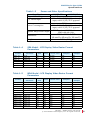
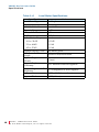
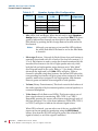
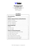
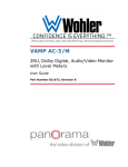
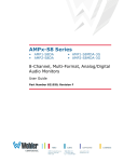
VAMP2 Series • VAMP2-SDA • VAMP2-MDA 2RU, Audio/Video Monitors with Level Meters User Guide Part Number 821667, Revision F © 2012 Wohler Technologies, Inc. and PANORAMA. All rights reserved. This publication is protected by federal copyright law. No part of this publication may be copied or distributed, stored in a retrieval system, or translated into any human or computer language in any form or by any means electronic, mechanical, manual, magnetic, or otherwise, or disclosed to third parties without the express written permission of Wohler Technologies. Reproduction Licensed users and authorized distributors of Wohler Technologies, Inc. products may copy this document for use with Wohler Technologies., Inc. products provided that the copyright notice above is included in all reproductions. Customer Support Wohler Technologies, Inc. 31055 Huntwood Avenue Hayward, CA 94544 www.wohler.com Phone: 510-870-0810 FAX: 510-870-0811 US Toll Free: 1-888-596-4537 (1-888-5-WOHLER) Web: www.wohler.com Sales: [email protected] Support: [email protected] Disclaimers Even though Wohler Technologies, Inc. has tested its equipment and software, and reviewed the documentation, Wohler Technologies, Inc. makes no warranty or representation, either express or implied, with respect to software, documentation, their quality, performance, merchantability, or fitness for a particular purpose. Wohler Technologies, Inc. reserves the right to change or improve our products at any time and without notice. In no event will Wohler Technologies, Inc. be liable for direct, indirect, special, incidental, or consequential damages resulting from any defect in the hardware, software, or its documentation, even if advised of the possibility of such damages. Some states do not allow the exclusion or limitation for incidental or consequential damages, so the above exclusion or limitation may not apply to you. Printing This document is intended to be printed on a duplex printer, such that the copy appears on both sides of each page. This ensures that all new chapters start on a right-facing page. This document looks best when printed on a color printer since some images may be indistinct when printed on a black and white printer. Other Technologies and Products Dolby, Dolby Digital, Dolby D, and Dolby E are registered trademark of Dolby Laboratories, Inc. Microsoft Windows, and Internet Explorer are registered trademarks of Microsoft Corporation. Last Update June 22, 2010 ii 821667: VAM P 2 S er ie s U s e r G u i d e © 2 0 1 2 Wo h l e r Tec h n o l o g i e s , I n c. A l l r i g h t s r e s er ve d . VAMP2 Series User Guide Introduction Overview The VAMP2 Series multi-format, multi-channel monitors are complete, exceptionally high quality stereo video/audio monitoring solutions available in a compact 2RU rack space with numerous input and output features that make these units ideal for facility-wide monitoring of analog/digital audio and video signals. Topics Topics Introduction Page 1 Safety Instructions 2 Applications 5 Features 5 Specifications 7 Front Panel Features 11 Rear Panel Connectors 15 Technical Functional Overview 22 8 2 1 6 6 7 : VA M P 2 S e r i e s Us e r G u i d e © 2 0 1 2 Wo h l e r Tec h n o l o g i e s, I n c. A l l r i g h t s r e s er ved . 1 VAMP2 Series User Guide S a f e t y I n s tr u c ti o n s Safety Instructions IMPORTANT: 1. Read, keep, and follow all of these instructions; heed all warnings. 2. Do not use this equipment near water. 3. Use only a dry cloth to clean the equipment. 4. Do not block any ventilation openings. Install only in accordance with the instructions in the section entitled, “Installation Recommendations” on page 3. 5. Do not install near any heat source such as a radiator, heat register, amplifier, or stove. 6. Do not expose the equipment to rain or moisture. 7. Do not attempt to plug the unit into a two-blade outlet (with only two prongs of equal width). By design, these monitors will only plug into a three-prong outlet for your safety. If the plug does not fit into your outlet, contact an electrician to replace the obsolete outlet. 8. Protect the power cord from being walked on or pinched, particularly at plug’s source on the equipment and at the socket. 9. Use only the attachments/accessories specified by the manufacturer. 10. Unplug the equipment during lightning storms or when unused for long periods of time. 11. Refer all servicing to qualified service personnel. Servicing will be required under all of the following conditions: 2 821667: • The equipment has been damaged in any way, such as when the power-supply cord or plug is damaged. • Liquid had been spilled or objects have fallen onto the equipment. • The equipment has been exposed to rain or moisture. • The equipment does not operate normally. • The equipment has been dropped. VAM P 2 S er ie s U s e r G u i d e © 2 0 1 2 Wo h l e r Tec h n o l o g i e s , I n c. A l l r i g h t s r e s er ve d . VAMP2 Series User Guide I n s ta l la t i o n R e c o m me n d a t io n s Installation Recommendations Unpacking Unpack the VAMP2 Series monitor from the shipping container and inspect all components for shipping damage. If you find any damage, notify the shipping carrier for claims adjustments. Compare the shipping box contents to the packing slip. Contact Wohler’s customer support personnel about any discrepancies. (Wohler’s contact information in on the copyright page ii, of this manual). Heat Dissipation The ambient temperature inside the mounting enclosure should not exceed 40° Celsius (104° Fahrenheit). Adjacent devices can be rack mounted (or stacked) in proximity to the unit if the above temperature is not exceeded. Allow a 1RU (1.75”/44.45mm) space above and below the unit for air circulation. Important: The heat generated by the power amplifiers, power supplies, and other components is vented by slots in the side of the unit. Therefore, as a safety precaution, we advise you to be sure to allow proper ventilation on both sides of the unit. Rack Mounting You should install the monitor into a standard 19" rack and requires a maximum of 4RU of rack space (the 2RU unit, plus 1RU above and below). Also, install it as close to the operator’s direct viewing angle as possible as LCD screens can appear to display anomalies outside this viewing angle. Note: In PAL mode operation, the LCD driver discards every seventh line of active video so an entire video frame fits within the display screen. This is normal for most LCDs currently on the market. 8 2 1 6 6 7 : VAM P 2 S e r i e s U s e r G u i d e © 2 0 1 2 Woh l er Te c h n o l o g i es , I n c . A ll r i g h t s r e se r ve d . 3 VAMP2 Series User Guide D e s c r ip t i o n Cable Connections Wohler recommends Beldon 8281 or Belden 1694A cables for analog video signals and Beldon 9451 cables for analog audio signals. Power Each unit comes with a standard 24VDC/3.0A internal power supply and connects an A/C mains power source (65W, 100 to 240 VAC, 50/ 60Hz) to the IEC connector provided on the rear panel of the unit. Electrostatic Discharge (ESD) As with most electronic equipment, static discharges can damage components within the unit. Take precautions to ensure your installation environment is not subject to ESD. Description In addition to their SDI inputs and outputs, both VAMP2 Series models are capable of monitoring AES and analog audio signals separately or in conjunction with CVBS and SDI video signals. In “Mix Mode” any combination of individual input channels may be selected for monitoring through the left and/or right speakers. Color coded LEDs above each level meter bar graph display indicate which channels are selected for monitoring and to which speaker they are assigned. Audio phase relationships are indicated by a bi-color (RED/GREEN) LED on the front panel. Audio input selection status is indicated by LEDs in close proximity to the selection buttons. Analog or AES audio signals may be monitored separately from the SDI and CVBS video inputs or a Track Video feature may be used to automatically route audio input to “follow” the video input signals. Four high-resolution 53-segment LED bar graph level meters exhibit simultaneous VU and PPM display characteristics to provide wide range visual monitoring of audio signals. Meters are tri-color (red/ amber/green) and have a dynamic range of 65 dB. Bar graph brightness is adjustable using controls located on the top cover. 4 821667: VAM P 2 S er ie s U s e r G u i d e © 2 0 1 2 Wo h l e r Tec h n o l o g i e s , I n c. A l l r i g h t s r e s er ve d . VAMP2 Series User Guide Applications Applications The VAMP2 Series is ideally suited to provide high quality multichannel and/or digital audio and video monitoring in a very compact form. Ideal for use in VTR bays, mobile production vehicles, teleconferencing installations, multimedia systems, satellite links, cable TV facilities, and on-air radio studios. Features Audio • Headphone jack (mutes speakers) • Two audio inputs on XLR connectors • LED indication of selection and mix settings • Four, 53-segment Tri-color LED bar graph level meters displaying simultaneous VU and PPM characteristics • Phase indication LEDs for each metered channel pair • Self-powered speaker system • Monitors and de-embeds HD/SD-SDI audio to AES and/or analog audio channels simultaneously • AES and CVBS audio inputs with loop-through outputs • Auxiliary analog or AES audio inputs may be monitored separately or in conjunction with the video inputs 8 2 1 6 6 7 : VAM P 2 S e r i e s U s e r G u i d e © 2 0 1 2 Woh l er Te c h n o l o g i es , I n c . A ll r i g h t s r e se r ve d . 5 VAMP2 Series User Guide Features Video • 4” active matrix TFT LCD display with 4:3 aspect ratio • Auto-detection of NTSC and PAL video formats • Digital signal status indication by LEDs • Two SD-SDI (SDA model) or HD/SD-SDI (MDA model) video inputs and two CVBS video inputs with A/B switching • Converts SDI video to CVBS (composite analog) video • Monitors and de-embeds one video channel simultaneously • Re-clocked output for selected SDI source • Analog (composite) output of selected video source • Re-clocked SD-SDI (SDA model) or HD/SD-SDI (MDA model) output and CVBS output de-embedded from the SDI input function regardless of other selection settings • LED indication of selection and mix settings Physical and Electrical • Low power consumption • Highest fidelity in minimum 2RU rack space. 6 821667: VAM P 2 S er ie s U s e r G u i d e © 2 0 1 2 Wo h l e r Tec h n o l o g i e s , I n c. A l l r i g h t s r e s er ve d . VAMP2 Series User Guide S p e ci f i c a t i o n s Specifications The VAMP2 Series monitors meet the specifications listed in Table 1–1 through Table 1–6 on page 10. Table 1–1 Audio Specifications Specification VAMP2-SDA VAMP2-MDA 2 Banks of 4 analog on DB-25 Inputs 2 Banks of 2 AES on BNC 2 Banks of 2 Balanced AES on DB-25 4 on Balanced AES from SDI on HD-15 Outputs Level Meters Level Meter Scale Level Meter Mid-scale Resolution Level Meter Dynamics Peak Acoustic Output: (@ 2 ft.) Output Analog Input Impedance Analog Input Overload Analog Reference Converted Analog Output (S/N Converted Analog Output (THD) Digital Reference AES Input Sampling Rate AES D to A Converter AES Termination (removable) Frequency Response (6th Octave) Hum and Noise Electrical Response 2 Speakers on Terminal Posts Four 53-segment high-resolution tri-color (red/yellow/green) LED bar graphs +0 dB to -66 dB 1 dB VU and PPM, simultaneous 96 dB SPL 10 W RMS (4 ), left and right, 14 W peak 27k balanced, minimum +24 dBu Balanced +8, +6, +4, or 0 dBu >90 dB <0.008% -20, -18, or -9 dBu 32 to 48 kHz, auto-select 24-bit, low jitter 110 Balanced; 75 Unbalanced 80 Hz to 16 kHz, (± 7 dB -10 dB @ 50 Hz, 22 kHz) > -68 dB below full output 20 Hz to -20 kHz (± 1 dB) 8 2 1 6 6 7 : VAM P 2 S e r i e s U s e r G u i d e © 2 0 1 2 Woh l er Te c h n o l o g i es , I n c . A ll r i g h t s r e se r ve d . 7 VAMP2 Series User Guide S p e c if i c a ti o n s Table 1–1 Audio Specifications (Continued) Specification Electrical Distortion Acoustic Distortion Table 1–2 VAMP2-MDA < 0.15% at any level below input threshold < 1.5% Typical at frequencies above 200 Hz; 6% or less at worst case Video Specifications Specification Inputs VAMP2-SDA VAMP2-SDA 2 SD/SDI on BNC VAMP2-MDA 2 HD/SD-SDI on BNC 2 CVBS on BNC 2 CVBS on BNC 1 Selected Video on BNC Outputs 1 CVBS from SDI on BNC 2 CVBS Loop on BNC CVBS Video Formats NTSC/PAL auto-detecting CVBS Signal Input Type NTSC 525/60 or PAL 625/50 Screen Type/Size 4” (96 x 76 x 6.5 mm) High-resolution (Diagonal) LCD, active matrix TFT Brightness, Chroma, Tint (NTSC only) Display Image Controls and Contrast Aspect Ratio 4:3 Active Area (HxV) 3.23” H x 2.43” W (82.1 mm x 61.8 mm) Resolution (Dots x Lines) 1440 W x 234 V Resolution (Pixels x 480 H x 234 V Lines) Pixel Format (HxV) 1 Pixel = R+ G + B dots Pixel Pitch (HxV) 0.171 mm W x 0.264 mm H Pixel response Time 15 ms rising; 20 ms falling (typical) Color Configuration RGB Delta Number of Colors 262,000 Viewing Angle Top=10°, Bottom=30°, Left=45°, Right=45° Contrast Ratio 150 (typical) White Luminance 250 NITs (cd/m2) typical (Brightness) Backlight Type LED LED Backlight Life 10,000 hours (min.) to specified reduction 8 821667: VAM P 2 S er ie s U s e r G u i d e © 2 0 1 2 Wo h l e r Tec h n o l o g i e s , I n c. A l l r i g h t s r e s er ve d . VAMP2 Series User Guide S p e ci f i c a t i o n s Table 1–3 Power and Other Specifications Specification Magnetic Shielding A/C Mains Input Power Consumption Speaker Amp Power Output Dimensions Weight Table 1–4 Format SDTV, 54 SDTV, 36 SDTV, 27 SDTV, 54 SDTV, 36 SDTV, 27 Table 1–5 Format SDTV, 54 SDTV, 36 SDTV, 27 SDTV, 54 SDTV, 36 SDTV, 27 HDTV, 74.25 HDTV, 74.25 HDTV, 74.25 HDTV, 74.25 HDTV, 74.25 HDTV, 74.25 HDTV, 74.25 VAMP2-SDA VAMP2-MDA <1 Gauss any adjacent surface 100 to 240 VAC, 50/60 Hz universal input, with UL/CE/TUV approval 50 W max 100 to 240 VAC, 50/60 Hz universal input, with UL/CE/TUV approval 20 W Transient/ 11 W Continuous RMS each side (4 3.5” H x 19” W x 9.5” D (89 mm H x 483 mm W x 241 mm D) 11.5 lbs. (5.2 kg) SDA Model - LCD Display Video Raster Format Parameters Scan Format Standards RP 174 SMPTE 267 SMPTE 125 ITU-R BT 601.5 ITU-R BT 601.5 ITU-R BT 601.5 Frame Rate 60 60 60 50 50 50 Lines 525 525 525 625 625 625 Active Lines 507/487 507/487 507/487 577 577 577 Samples 3432 2288 1716 3456 2304 1728 Active Samples 2880 1920 1440 2880 1920 1440 MDA Model - LCD Display Video Raster Format Parameters Scan Format Standards RP 174 SMPTE 267 SMPTE 125 ITU-R BT 601.5 ITU-R BT 601.5 ITU-R BT 601.5 SMPTE 260 SMPTE 274 SMPTE 274 SMPTE 274 SMPTE 274 SMPTE 295 SMPTE 274 Frame Rate 60 60 60 50 50 50 30 30 30p 25 25p 25 25p Lines 525 525 525 625 625 625 1125 1125 1125 1125 1125 1250 1125 Active Lines 507/487 507/487 507/487 577 577 577 1035 1080 1080 1080 1080 1080 1080 Samples 3432 2288 1716 3456 2304 1728 2200 2200 2200 2640 2640 2376 2750 Active Samples 2880 1920 1440 2880 1920 1440 1920 1920 1920 1920 1920 1920 1920 8 2 1 6 6 7 : VAM P 2 S e r i e s U s e r G u i d e © 2 0 1 2 Woh l er Te c h n o l o g i es , I n c . A ll r i g h t s r e se r ve d . 9 VAMP2 Series User Guide S p e c if i c a ti o n s Table 1–6 Level Meter Specifications Specification Level Meter Type Segment Quantity Level Meter Scale Dynamic Range Mid-scale Resolution Bar Graph Length Indication Accuracy 821667: Bar Graph 53 0 to -66 dB 66 dB 1 dB 2.22” (56.4 mm) +10 to -30 dB ± 0.2 dB -31 to -44 dB ± 0.3 dB -45 to -55 dB Segment Display Colors Peak Emission Wave Length Segment Brightness (20 mA) Segment Brightness Uniformity Adjacent Segment “Off” Brightness Segment Size Segment Pitch 10 Values ± 0.5 dB red, amber, green Green=570 nm; Red=630nm 3.5 mcd <10% difference between segments <1% of brightness of active segment 0.158” x 0.04” (4 mm x 1 mm) 0.039” (.99 mm) VAM P 2 S er ie s U s e r G u i d e © 2 0 1 2 Wo h l e r Tec h n o l o g i e s , I n c. A l l r i g h t s r e s er ve d . VAMP2 Series User Guide Front Panel Features Front Panel Features Figure 1–1 VAMP2 Series Front Panel Speaker Assign Speaker Mix Volume Level Meters Phase Channel LEDs SDI Group Color Tint LCD Video Video Source Mix Assign Speaker Select SDI Select Balance Audio Audio Source Analog/AES Select 1 & 2 Headphones Contrast Brightness Speakers • Speakers: The speaker system is comprised of two full-range speakers (left and right). • Speaker Assign (Push Buttons, Left and Right): The general function of each of these two buttons assigns any single channel or group of channels (four maximum) separately to each of the two speakers (left and right). Table 1–8 below shows the function of each consecutive button push. Note that pushing either button a sixth time starts the cycle over. Table 1–7 Speaker Assign Mix Configuration Button Button Push Channel LED LED Color Speaker Assignment Left 1 2 3 4 5 1 2 3 4 Left Mix Green Left 8 2 1 6 6 7 : VAM P 2 S e r i e s U s e r G u i d e © 2 0 1 2 Woh l er Te c h n o l o g i es , I n c . A ll r i g h t s r e se r ve d . 11 VAMP2 Series User Guide Front Panel Features Table 1–7 Speaker Assign Mix Configuration Button Right Button Push Channel LED LED Color Speaker Assignment 1 2 3 4 5 1 2 3 4 Right Mix Amber Right • Mix (LEDs, Left and Right): When the left and/or right Speaker Assign button is pushed a fifth time, its associated Mix LED glows green to indicate that channels can be added to that speaker mix (Mix Mode) by pushing the Mix Assign Buttons located under the level meters. Note: Although you can turn on just one Mix LED (without the other) both Mix LEDs must be on for the Mix Mode to function. • Mix Assign (Buttons, 1 through 4): Each of these four push buttons is separately associated with one of each of the four lever meters (1, 2, 3, or 4). Each button is used to assign the channel monitored by the associated level meter to the left or right speaker mix only when both the left and right speaker assign buttons are in “Mix Mode” (the 5th push button in the cycle. Refer to *** for details.) When in mix mode the right and/or left Mix LEDs will glow. When a channel is selected using these buttons, the channel LED above the corresponding level meter will glow green when assigned to the left speaker, amber when assigned to the right speaker, and alternate between green and amber when assigned to both speakers. • Volume (Rotary Potentiometer): This knob controls the loudness of the audio reproduced by the internal speakers, external speakers, or connected headphone. • Video Source (Push Button and LEDs): This button selects one of three signal sources for monitoring: SDI, CVBS 1, or CVBS 2. Repeatedly pressing the source select button steps through each of the three selections. One of the three indication LEDs (SDI, CVBS 1, or CVBS 2) will glow to indicate the selected signal source. When SDI is selected, you can select one of the two available SDI inputs on the rear panel for monitoring using the SDI Select button. Note that the SDI LED will glow green if the selected SDI signal is locked, or red if the signal is unlocked. 12 821667: VAM P 2 S er ie s U s e r G u i d e © 2 0 1 2 Wo h l e r Tec h n o l o g i e s , I n c. A l l r i g h t s r e s er ve d . VAMP2 Series User Guide Front Panel Features When CVBS 1 or 2 is selected, one of the two corresponding CVBS inputs on the rear panel is selected for monitoring. See the Audio Select button (page 14) for information about selecting audio inputs with video monitoring. Note that the selected CVBS LED will glow green when selected. • Channel Indicators (LEDs, 1 through 4): These four LEDs (1, 2, 3, and 4) indicate when the associated channel is assigned to one or both speakers. When these LEDs glow green, the channel is assigned to the left speaker, when amber, the right speaker. When it alternates between green and amber, the channel is assigned to both speakers. The LEDs are not lit when the channel is not assigned to either speaker. • Level Meters (53-Segment Bar Graph): These high-resolution, LED bar graph meters display audio levels for metered audio signals. Ballistics for these meters are factory set to display a single floating PPM dot above a VU bar; each segment’s color is fixed according to its position on the scale. Reference level is +4 dBu. Dynamic range for these meters is 66 dB. • Phase (Bi-Color Red/Green LED): The audio phase indicator shows the phase relationships between audio channels A (1) and B (2). The LED indicates the average phase condition by glowing green for in-phase conditions or red for out-of-phase conditions. While it is normal for stereo signals to contain some intermittent instantaneous out-of-phase and in-phase conditions (flickering red) a steady red glow of the phase indicator almost always indicates an out-of-phase alarm condition. • Speaker Select (Push Button): This switch routes the audio signal to either the internal speakers or to external speakers connected to the terminal posts on the rear panel. • SDI Signal Lock (LED): When the monitor receives a valid and locked SDI video signal, this LED lights green. • SDI Select (SEL) (Push Button and LED Indicators): This control selects one of two inputs, HD/SD-SDI (MDA model) or SD-SDI source (SDA model) for monitoring when either the Video Source select button or the Audio Source select button is set to SDI. When the SDI 1 source is selected for monitoring, the LED will not be lit. When the SDI 2 source is selected, the LED indicator will glow green. 8 2 1 6 6 7 : VAM P 2 S e r i e s U s e r G u i d e © 2 0 1 2 Woh l er Te c h n o l o g i es , I n c . A ll r i g h t s r e se r ve d . 13 VAMP2 Series User Guide Front Panel Features • Headphone Jack (1/4” Connector): Select the headphone audio sources as you would for the internal speakers. When you plug in headphones, the internal or external speakers will mute. • Tint (TNT): Turn this potentiometer to adjust the color hue of the video image (for NTSC signals only). • Chroma (COL): Turn this potentiometer to adjust the color saturation of the video image. • Brightness (BRT): Turn this potentiometer to adjust the brightness of the video image. • Contrast (CNT): Turn this potentiometer to adjust the contract of the video image. • LCD Video (TFT): This screen displays input video sources. • SDI Group Select (Push Button): This button selects the SDI group (1, 2, 3, or 4) for monitoring when Audio Source select button is set to SDI or set to Tracks Video, and SDI is the video source. One of the four LEDs will glow green to indicate the selected group. • Audio Analog/AES Select (Push Button and Indication LEDs): These two push buttons, AUX 1 and AUX 2, toggle between the AES and analog (ANLG) inputs for the corresponding AUX 1 and AUX 2 input sections on the rear panel. When the analog input is selected, the LED is not lit. When the AES input is selected, the LED glows green. • Balance (Rotary Potentiometer): This control pans the volume balance between the left and right speakers. If you adjust the balance hard to the left or right, the system retains a slight Left/ Right channel mix so phase discrepancies remain audible. • Audio Source (Push Button and Indication LEDs): This push button steps through the four audio sources below: 14 821667: • SDI: Monitors the audio de-embedded from the SDI inputs on the rear panel. • AUX 1: Monitors the audio input to the AUX 1 (analog or AES) inputs on the rear panel. • AUX 2: Monitors the audio input to the AUX 2 (analog or AES) inputs on the rear panel. VAM P 2 S er ie s U s e r G u i d e © 2 0 1 2 Wo h l e r Tec h n o l o g i e s , I n c. A l l r i g h t s r e s er ve d . VAMP2 Series User Guide Rear Panel Connectors • Tracks Video: This setting will monitor the AUX audio source associated with the selected CVBS video source. Table 1–8 below shows the AUX input that are associated with the CVBS inputs with this setting. Table 1–8 Tracks Video Setting Configuration Video Source Audio Source SDI SDI CVBS 1 AUX 1 AES 1 CVBS 2 AUX 2 AES 2 Analog Inputs AES Inputs N/A Channels 1 & 2 Channels 3 & 4 Channels 5 & 6 Channels 7 & 8 Rear Panel Connectors Figure 1–2 VAMP2 Series Rear Panel Connectors CVBS 2 In and Loop Out RS-232 #2 AUX 1 Input 1 (left) CVBS 1 In and Select AUX 2 Input 1 (right) Loop Out RS-232 #1 Selected Balanced AES Balanced AES In Video CVBS External Speakers Out from SDI and Loop Out Out Terminator IN CVBS 1 LOOP IN CVBS 2 LOOP BAL AES OUT FROM SDI SEL VID OUT HI Z 13 BAL AES IN / LOOP RS232 #1 13 1 25 1 25 14 5 14 LEFT EXTERNAL SPEAKERS RIGHT 1 9 6 75 CVBS YEAR RS232 #2 OPT A 5 IN 1 OUT 1 AES IN HI Z SDI AUX 2 2 3 4 5 6 7 LEFT 8 SELECTED ANALOG OUT RIGHT 2 1 AES IN 2 HI Z 1 14 13 25 ANALOG IN 75 RS-232 #2 SDI Out SDI In (1 & 2) REF 1 13 25 MADE IN U.S.A. Option B Converted CVBS Out 1 14 1 6 OPT B Power Option A 13 25 AUX 1 IN 2 VAMP2-SDA WWW.PANORAMADTV.COM 1 9 100-240 VAC 50/60 Hz 1.0 A SERIAL NUMBER METERED ANALOG OUT VAMP2-MDA MONTH CONVERTED VIDEO OUT 1 14 75 AES Terminators AUX 1 Input 2 (left) AUX 2 Input 2 (right) Selected Analog Out Reference 1 Metered Analog Out Analog In • CVBS In and Loop Out (1 & 2 on BNC): These input connectors accept standard CVBS (composite analog) video signals. To monitor the video from these inputs, set the Video Source select button to 8 2 1 6 6 7 : VAM P 2 S e r i e s U s e r G u i d e © 2 0 1 2 Woh l er Te c h n o l o g i es , I n c . A ll r i g h t s r e se r ve d . 15 VAMP2 Series User Guide R e a r P a n e l C o n n e ct o r s CVBS 1 or 2. See CVBS Terminator below for termination setting values. • CVBS Terminator (Four-Position DIP Switch): Termination for the CVBS (composite analog) input connectors is adjustable through the four-position DIP switch located between the two CVBS input sections (1 and 2). The switch section nearest the associated connector sets the termination for that connector (CVBS 1 = left; CVBS 2=right). Set the switch down to terminate or up to unterminate. • Selected Video Out (CVBS on BNC): This connector outputs the buffered, selected CVBS (composite analog) input (either 1 or 2). • Power (IEC-320 Connector): Attach a standard IEC-320 power cord between this connector and the mains power. The front panel power LED glows green when an operating voltage is present. • Option A (Rotary Switch on the MDA model, or Reset button on the SDA model): In the SDA model, this opening features a recessed, push button with a momentary reset function for the SD-SDI input module. Pressing the button with a small screwdriver or other tool will reset the SD-SDI input functions of the SDA unit. In the MDA model, this opening features a 10-position rotary switch for selecting related functions as shown in Table 1–9 below. Table 1–9 Position 0 1 2 3 4 5 6 7 8 9 Option A Switch Function Option A Switch Function (MDA Models Only) Bootload CVBS Output in NTSC CVBS Output in PAL CVBS Output is NTSC, Letterboxed when Input is HD CVBS Output in PAL, Letterboxed when Input is HD Reserved Hardware Reset Mode When set to positions 1, 2, 3, or 4, the signals from the CVBS video output and the video supplied to the internal LCD will be the format described for each position in the table, (NTSC or PAL) regardless of the input format. When set to positions 3 or 4, HD-SDI input signals are letterboxed, but SD-SDI input signals are not. Setting the 16 821667: VAM P 2 S er ie s U s e r G u i d e © 2 0 1 2 Wo h l e r Tec h n o l o g i e s , I n c. A l l r i g h t s r e s er ve d . VAMP2 Series User Guide Rear Panel Connectors switch to positions 8 or 9 resets the video scaler and the audio deembedder. • Option B (Rotary Switch): This opening features a 10-position rotary switch that is reserved for future use and should be left at the factory position of 1. • Converted CVBS Out (from SDI, BNC-F): This female BNC connector outputs CVBS (composite) video encoded from the selected SDI input. In the MDA model, HD-SDI signals are down-converted for proper representation in composite video format. A switch is also installed in the MDA model to allow selection of the video scaler for communication through the RS-232 #2 connector. This output functions regardless of other selection settings. This feature enables encoding of the SDI signal to CVBS independent of other monitoring functions (as long as a valid SDI signal is present at the associated input). • RS-232 #2 Select (Two-Position Select Switch on MDA model only): This two-position slide switch is used to select the video scaler (up) or the audio de-embedder (down) for communications through the RS-232 #2 connector. • RS-232 #2 (DB-9): In the SDA model, this DB-9 connector is used for downloading programming, setup, and diagnostic information into and out of the audio de-embedder. In the MDA model, it is used for downloading programming, setup, and diagnostic information into and out of the audio de-embedder or the video scaler. The MDA model also features a two-position slide switch for selecting the module that communicates through the connector. Note: You cannot input signals into both the balanced and unbalanced connectors within the same AUX section. • SDI In (1 & 2 on BNC): The In 1 and In 2 BNC connectors accept either stand SD-SDI (SDA model) or HD/SD-SDI (MDA model) audio signals. In the SDA model, only standard SD-SDI audio/video signals are accepted at these two BNC input connectors. In the MDA model, these two BNC connectors accept both highdefinition HD-SDI and standard SD-SDI audio/video signals (HDSDI signals are automatically down converted for monitoring). 8 2 1 6 6 7 : VAM P 2 S e r i e s U s e r G u i d e © 2 0 1 2 Woh l er Te c h n o l o g i es , I n c . A ll r i g h t s r e se r ve d . 17 VAMP2 Series User Guide R e a r P a n e l C o n n e ct o r s To monitor video from these inputs, set the following: • The Video Source select button to SDI, • The SDI Input select button to SDI input either (In 1 or In 2), and • The SDI Group select button to the SDI Group of choice (1, 2, 3, or 4). To monitor audio (only) from these inputs, set the following: • The Audio Source select button to SDI, • The SDI Input select button input either (In 1 or In 2), and • The SDI Group select button to the SDI Group of choice (1, 2, 3, or 4). Even if SDI is not selected for monitoring through the unit, you can still select the SDI input (In 1 or In 2) and use the re-clocked SDI Output connector and CVBS Converted Video Output (from an SDI input) Connector regardless of other settings. This feature enables processing of the SDI signal independent of the unit’s other monitoring functions. • SDI Out (BNC): The output BNC connector outputs a re-clocked HD/SD-SDI signal derived from the selected HD/SD-SDI input. This output functions regardless of other selection settings enabling output of the re-clocked HD/SD-SDI signal independent of the unit’s other monitoring functions (as long as a valid HD/SD-SDI signal is present at the input). • (Optional) Unbalanced AES Out from SDI (HD-15): Unbalanced AES signals de-embedded from the selected SDI input are output from this HD-15 connector. See Figure 1–3 on page 19 for the pin-out for this connector. Note: 18 821667: You can request the optional Unbalanced AES Out from SDI HD-15 connector instead of the Balanced AES Out from SDI DB-25 connector at the time you place your order. VAM P 2 S er ie s U s e r G u i d e © 2 0 1 2 Wo h l e r Tec h n o l o g i e s , I n c. A l l r i g h t s r e s er ve d . VAMP2 Series User Guide Rear Panel Connectors Figure 1–3 Unbalanced AES Out from SDI HD-15 Connector Pin-Out • Balanced AES Output from SDI Input Connector (Optional DB-25): AES signals de-embedded from the selected SDI input are output from this DB-25 connector, configured for balanced connections (110 impedance). Pin-out information for the balanced DB-25 connector is shown in Figure 1–4 below. Figure 1–4 Balanced AES Output from SDI In DB-25 Connector Pin-Out • Balanced AES In with Loop-Out (DB-25): This DB-25 connector accepts AES audio signals and is configured for balanced connections (110 impedance). This connector features internally connected passive loop-through outputs of the input signals. See Figure 1–5 below for pin-out information. (Refer to the AES Input Termination DIP Switch on page 24 for termination settings.) See the Audio Source Select and Audio Analog/AES Input Select buttons for selecting this input for monitoring. 8 2 1 6 6 7 : VAM P 2 S e r i e s U s e r G u i d e © 2 0 1 2 Woh l er Te c h n o l o g i es , I n c . A ll r i g h t s r e se r ve d . 19 VAMP2 Series User Guide R e a r P a n e l C o n n e ct o r s Figure 1–5 Balanced AES In with Loop Out DB-25 Connector Pin-Out AES Input AUX 2 AUX 1 Loop-Through Output AUX 1 AUX 2 AES1 AES2 AES1 AES2 AES1 AES2 AES1 AES2 • RS-232 #1 (DB-9): This connector provides an interface for downloading the user interface, unit functionality, AES programming, setup, and diagnostic information into and out of the unit. • AES Input Termination (DIP Switch): Termination for both pairs (AUX 1 and AUX 2) of the AES inputs (AES IN, 1 or 2) is adjustable through the four-position DIP switches located between each pair of input connectors. The switch section nearest the associated connector sets the termination for that connector. Move the switch down (75 , balanced; 110 unbalanced) to terminate the connector, or up (HI Z) to unterminate. See Figure 1–6 below and Figure 1–7 on page 21 for switch ID settings. Figure 1–6 AUX 1 - AES Input Termination AUX 1, AES 1 Balanced AUX 1, AES 1 Unbalanced AUX 1, AES 2 Balanced AUX 1, AES 2 Unbalanced Up: Unterminated Down: Terminated 1 20 821667: 2 3 4 VAM P 2 S er ie s U s e r G u i d e © 2 0 1 2 Wo h l e r Tec h n o l o g i e s , I n c. A l l r i g h t s r e s er ve d . VAMP2 Series User Guide Rear Panel Connectors Figure 1–7 AUX 2 - AES Input Termination AUX 2, AES 1 Balanced AUX 2, AES 1 Unbalanced AUX 2, AES 2 Balanced AUX 2, AES 2 Unbalanced Up: Unterminated Down: Terminated 1 2 3 4 • AUX 1 & 2 Input 1 & 2 (on BNC): The four BNC connectors in the AUX 1 and AUX 2 input sections accept standard AES audio signals and are configured for unbalanced connections (75 impedance). See the Audio Source Select button and the Audio Analog/AES Select button for instructions for selecting these inputs for monitoring. • External Speakers (Speaker Binding Posts, Left and Right): Connect external speakers to these binding post terminals. The left pair outputs the signals as selected for the left speaker and the right pair outputs the signals as selected for the right speaker. The binding post terminals in each output pair are color-coded for polarity; red is positive (left terminal) and black is negative (right terminal). An external amplifier is not needed to drive the external speakers. • VAMP2 Analog In & Metered Analog Out (DB-25-F): This connector accepts balanced, low impedance, line level analog signals. See Figure 1–8 below for pin-out information. This connector has the same pin-out as the Tascam analog DB-25. Figure 1–8 Analog In and Metered Analog Out Connector Pin-Out 8 2 1 6 6 7 : VAM P 2 S e r i e s U s e r G u i d e © 2 0 1 2 Woh l er Te c h n o l o g i es , I n c . A ll r i g h t s r e se r ve d . 21 VAMP2 Series User Guide Technical Functional Overview • Selected Analog Out (XLR-M): These two male, three-pin XLR connectors are analog outputs of the sources selected for the left and right speakers. See Audio Source, Speaker Assign, and Mix Assign functions for selection reference. Figure 1–9 XLR Pin-Out Technical Functional Overview Figure 1–10 on page 23 and Figure 1–11 on page 24 illustrate the overall functionality of the VAM2 Series monitors. 22 821667: VAM P 2 S er ie s U s e r G u i d e © 2 0 1 2 Wo h l e r Tec h n o l o g i e s , I n c. A l l r i g h t s r e s er ve d . VAMP2 Series User Guide T e c h n i c al F u n c ti o n al O v e r v ie w Figure 1–10 Metered Analog Out 4 Loop-Through Balanced AES Input and Loop Output AES Input 1 AES Input 2 AES Input 1 AES Input 2 4x4 Audio Source Matrix HD/SD SDI Output CVBS Video Output CVBS In 1 CVBS Loop Out 1 Headphone Aux 1 AES In 2 4 Volume Balance 2 Aux 2 AES In 2 8-Channel A/D Converter Unbalanced or Balanced AES Output From SDI SD-SDI 1 2 3 4 2 Analog Input (Aux 1 & 2) HD/SD SDI Input 1 HD/SD SDI Input 2 VAMP2-SDA Block Diagram Mix Assign 4-Channel D/A Converter Aux 1 & 2 Analog In Demuxed AES From SDI Input SDI to AES Demux SDI Receiver 2 SDI Input Select RS 232 Reference Select 1 Reclocked SDI Out G1 G2 G3 G4 uP Control / U.I. 4 Group Select L L Stereo Analog Amplifier 4x2 Mixer Video DAC Analog Stereo Output of Selected Source (RP) 12C Buss SW Logic Config. Ref Level Speaker Assign Video Encoder Video Source Select From SDI Input CVBS From SDI CVBS 1 CVBS 2 Right Speaker R R 4 Int/Ext Speaker Relay Left Speaker Phase Indication Phase LED R- R+ External Speaker L- L+ Output (RP) Display Controls TINT BRIGHTNESS 4” (4:3) Active Matrix TFT LCD Screen COLOR CONTRAST CVBS In 2 Loop Out 2 8 2 1 6 6 7 : VAM P 2 S er ie s U s e r G u i d e © 2 0 1 2 Woh l e r Te c h n o l o g i es , I n c . A l l r i g h t s r e se r ve d . 23 VAMP2 Series User Guide T e c h n i c al F u n c ti o n al O v e r v ie w Figure 1–11 Metered Analog Out 4 Loop-Through Balanced AES Input and Loop Output AES Input 1 AES Input 2 AES Input 1 AES Input 2 4x4 Audio Source Matrix HD/SD SDI Output CVBS Video Output CVBS In 1 CVBS Loop Out 1 Headphone Aux 1 AES In 2 4 Volume Balance 2 Aux 2 AES In 2 8-Channel A/D Converter Unbalanced or Balanced AES Output From SDI SD-SDI or HD-SDI 1 2 3 4 2 Analog Input (Aux 1 & 2) HD/SD SDI Input 1 HD/SD SDI Input 2 VAMP2 MDA Block Diagram Mix Assign 4-Channel D/A Converter Aux 1 & 2 Analog In Demuxed AES From SDI Input SDI to AES Demux SDI Receiver 2 SDI Input Select RS 232 Reference Select 1 Reclocked SDI Out G1 G2 G3 G4 uP Control / U.I. 4 Group Select L L Stereo Analog Amplifier 4x2 Mixer Video DAC Analog Stereo Output of Selected Source (RP) 12C Buss SW Logic Config. Ref Level Speaker Assign Video Encoder Video Source Select From SDI Input CVBS From SDI CVBS 1 CVBS 2 Right Speaker R R 4 Int/Ext Speaker Relay Left Speaker Phase Indication Phase LED R- R+ External Speaker L- L+ Output (RP) Display Controls TINT BRIGHTNESS 4” (4:3) Active Matrix TFT LCD Screen COLOR CONTRAST CVBS In 2 Loop Out 2 8 2 1 6 6 7 : VAM P 2 S er ie s U s e r G u i d e © 2 0 1 2 Woh l e r Te c h n o l o g i es , I n c . A l l r i g h t s r e se r ve d . 24