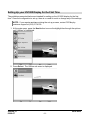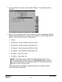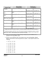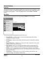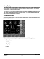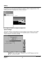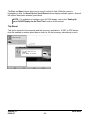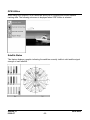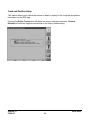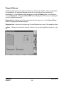
1
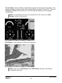
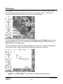
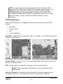
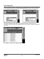
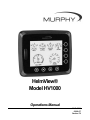
HelmView®
Model HV1000
Operations Manual
00-02-0604
08-08-07
Section 78
In order to consistently bring you the highest quality, full featured products, we reserve the right to change our
specifications and designs at any time. The latest version of this manual can be found at www.fwmurphy.com.
Warranty - A limited warranty on materials and workmanship is given with this FW Murphy product. A copy of
the warranty may be viewed or printed by going to www.fwmurphy.com/support/warranty.htm
Please read the following information before installing.
BEFORE BEGINNING INSTALLATION OF THIS MURPHY
PRODUCT:
•
Read and follow all installation instructions.
•
Please contact FW MURPHY immediately if you have any
questions.
Table of Contents
Product Information................................................................................................................ 1
Display Features ..........................................................................................................1
Mounting Options .........................................................................................................2
Remote Keypad ...........................................................................................................3
HV1000 Navigation.................................................................................................................. 5
Fixed Buttons ...............................................................................................................5
Virtual Buttons..............................................................................................................6
Menu ............................................................................................................................7
Popup...........................................................................................................................7
Setting Up your HV1000 Display for the First Time ............................................................ 8
Product Features................................................................................................................... 12
Power Up ...................................................................................................................12
Main Menu .................................................................................................................12
Gauge Display............................................................................................................13
GPS Display...............................................................................................................16
Engine Diagnostics ....................................................................................................18
Fault Code Pop-ups ...................................................................................................20
User Settings..............................................................................................................21
Utilities .......................................................................................................................23
GPS Utilities ...............................................................................................................25
Reprogramming the HV1000 Display.................................................................................. 29
Specifications........................................................................................................................ 30
(THIS PAGE INTENTIONALLY LEFT BLANK)
Product Information
The HelmView™ Model HV1000 display is designed for instrumentation and control on
electronically controlled engines communicating using SAE J1939 and NMEA 2000. The
HV1000 display is a multifunction tool that enables equipment operators to view many different
engine or transmission parameters and service codes, and can support up to four engines
simultaneously.
Display Features
Fault Lights
These indicators, located in the top two corners of the unit, will light up when a fault occurs.
The unit will display an amber light for a warning or a red light for a shutdown condition. A
corresponding pop-up message describing the fault may also be displayed on the screen.
Keypad Indicator Light
Located on the bottom left of the unit, the keypad indicator lights up each time one of the touch
capacitive buttons is pressed.
SD Card Slot
This slot is used for reprogramming the unit. If using the GPS Maps package, it is also used
for the Navionics map cards to retrieve the maps. It is sealed from the rest of the unit. It
should remain covered to keep out water, dust, and other contaminants.
Section 78
08-08-07
00-02-0604
-1-
Mounting Options
Two mounting options are provided for the HV1000 display. The in-dash mounting option will
require a hole to be cut for insertion of the display. A template is provided with the depth and
dimensions of the display for easy installation. The gimbal-mount method enables the display
to be installed on top of the dash. The gimbal design allows rotating and tilting the unit for the
best display position for the operator’s viewing.
For complete installation and wiring instructions, refer to the “HelmView Installation Manual”
included with your HV1000 display.
NOTE: Do not leave plastic installation template installed with the display.
This will create a condition where the protective cover will engage too
tightly.
Section 78
08-08-07
00-02-0604
-2-
Remote Keypad
The Remote Keypad works with Murphy’s PV1000 and HV1000 model displays. It allows a
user to enter keypad commands whenever display installations are not conveniently located for
easy access.
The keypad contains the same navigation, menu and selection keys as found on the displays,
making it an easy transition to use. Fault lights, just like the ones found on the displays, are
located in the corners of the keypad. An audible alarm with a one-touch key for temporarily
disabling is provided, making it easy to recognize and address faults and alarms.
Specifications
I.
Electrical
I.
Processor: PIC18F2510
Flash Memory: 32 Kbytes
RAM: 1536 bytes SRAM
Backlighting: LED, 7400 mcd
Operating Voltage: 6 to 32 VDC, protected against
reverse polarity and load-dump
Power Consumption: 3.2 W maximum
Connection: 2 Deutsch DT 6-pin connectors
Keyboard: 7 Membrane Switch Keys
Audible Alarm: 70dB minimum
I.
Mechanical
Mounting Type: Screw-on clamp
Dimensions (W x H):
• 3.88 x 3.88 inch (Landscape)
• Panel Mount Depth – 0.5922 inch
• Unit Depth – 2.173 inch
Cutout for Panel Mounting
(Diameter): 2.062 inch
Case Material: Polycarbonate
Weight: 0.4 lb (180 g)
Environmental
Operating Temperature: -40 to 70°C (-40° to 158°F)
Storage Temperature: -55 to 85°C (-67° to 185°F)
Emissions: SAE J1113, IEC 60945, EN 12895,
EN 61000
Section 78
08-08-07
00-02-0604
-3-
Product Dimensions
Electrical Connection
Section 78
08-08-07
00-02-0604
-4-
HV1000 Navigation
Navigating the HV1000 display is accomplished using two sets of buttons - one fixed and one
virtual - to access menus, pop-ups, and make selections from available options. Each time a
button is pressed, confirmation of the button press is given by the amber light at the lower left
corner of the display.
Fixed Buttons
The fixed buttons run across the bottom of the display for Menu, Previous, Next, and Select
options. On some screens, Select may be replaced by other options such as Save, Exit, or
Popup. Previous and Next may also be represented as Up and Down.
Section 78
08-08-07
00-02-0604
-5-
Virtual Buttons
A column of vertical buttons located to the right of the display are virtual buttons. They will
change according to the options available for the screen being displayed.
Section 78
08-08-07
00-02-0604
-6-
Menu
The Menu can be accessed at any time, from any screen being displayed, by pressing the
Menu button.
The Menu button symbol
is always located in the first position of the fixed buttons.
Popup
The Popup button utilizes the virtual keys to the right of the display to provide shortcuts for
navigation and display options.
Section 78
08-08-07
00-02-0604
-7-
Setting Up your HV1000 Display for the First Time
The guidelines presented below are intended for setting up the HV1000 display for the first
time. Once the configuration is set up, there is no need to revisit or change any of the settings.
NOTE: If you require assistance during the set up process, contact FW Murphy
customer support at (918) 317-4100.
1. At the main menu, press the Next button to move the highlight bar through the options
until ‘Utilities’ is highlighted.
2. Press Select. The Utilities sub-menu is displayed.
Section 78
08-08-07
00-02-0604
-8-
3. From the ‘Utilities’ sub-menu, select ‘System Settings’. The following screen is
displayed.
4. With the cursor highlighting the ‘Wiring Config’ field, press the Scroll Up or Scroll
Down virtual buttons (located to the right of the display), to scroll through the list of
options. The field options consist of the following:
•
Custom
•
(A) Engine(s) – Single Harness Plug A-Port, Stbd
•
(B) Engine(s) – Single Harness Plug A-Stbd, Port
•
(C) Engines – Dual Harness Plug A&B-Port, Stbd
•
(D) Engines – Dual Harness Plug A&B-Stbd, Port
•
(E) NMEA – Plug D-Port, Stbd
•
(F) NMEA – Plug D-Stbd, Port
NOTE: This setting needs to match the wiring configuration for how your
HV1000 display was installed. Refer to the “Wiring Instructions” section of
the “HelmView Model HV1000 Installation Manual” for the associated wiring
diagrams for each of these options.
The following table is provided as a partial reference list of engines and their
appropriate wiring configuration.
Section 78
08-08-07
00-02-0604
-9-
Engine Type
Crusader
Single Engine
Configuration
Twin Engine **
Configuration
(A) Single Harness Plug A-Port, Stbd
Volvo non-EVC
Gas
(C) Dual Harness Plug A&B-Port,
Stbd
(A) Single Harness Plug A-Port, Stbd
Or
(B) Single Harness Plug A-Stbd, Port
(C) Dual Harness Plug A&B-Port, Stbd
Or
(D) Dual Harness Plug A&B-Stbd, Port
(E) Plug D-Port, Stbd
Or
(F) Plug D-Stbd, Port
(C) Dual Harness Plug A&B-Port, Stbd
Or
(D) Dual Harness Plug A&B-Stbd, Port
(C) Dual Harness Plug A&B-Port, Stbd
Or
(D) Dual Harness Plug A&B-Stbd, Port
(C) Dual Harness Plug A&B-Port, Stbd
Or
(D) Dual Harness Plug A&B-Stbd, Port
(E) Plug D-Port, Stbd
Or
(F) Plug D-Stbd, Port
Volvo Diesel or Gas (E) Plug D-Port, Stbd
EVC*
Cummins
(MerCruiser Diesel)
(C) Dual Harness Plug A&B-Port,
Stbd
Cummins HHP
(C) Dual Harness Plug A&B-Port,
Stbd
Caterpillar
(C) Dual Harness Plug A&B-Port,
Stbd
Yanmar
(E) Plug D-Port, Stbd
* A NMEA 2000 conversion module is needed. This can be purchased through Volvo Penta (P/N 3840277)
** The difference between A & B, E & F, and C & D is only the orientation of the data on the screen. In a twin
application the engines’ data may appear on the wrong side of the screen. Changing to the secondary option,
A to B, C to D, or E to F, will switch the data to the other side of the display.
5. When the correct setting for ‘Wiring Config’ is displayed, press the Next button to
advance to the ‘Plug Address’ field.
6. With the cursor highlighting the ‘Plug Address’ field, press the Scroll Up or Scroll
Down virtual buttons to scroll through the list of options. These options consist of the
following:
•
A:0 B:1 C:2 D:3
•
A:1 B:2 C:3 D:4
•
A:2 B:3 C:4 D:5
•
A:3 B:4 C:5 D:6
•
A:4 B:5 C:6 D:7
•
A:5 B:6 C:7 D:0
•
A:6 B:7 C:0 D:1
•
A:7 B:0 C:1 D:2
Section 78
08-08-07
00-02-0604
- 10 -
7. When the correct setting for ‘Plug Address’ is displayed, press the Save button. The
‘Utilities’ sub-menu is displayed.
Once the ‘System Settings’ have been configured, you may want to set up your display options
and favorites. For information on this process, refer to the “User Setting” section located in
this manual.
Section 78
08-08-07
00-02-0604
- 11 -
Product Features
Power Up
The HelmView display is most frequently installed with power connected to the ignition. When
the ignition is turned on, the HelmView display powers up and the engine health statistics can
be viewed via preset gauges. To see more gauge screens, press the Next or Previous
buttons.
Main Menu
The main menu is activated at any time by pressing the Menu key on the display.
The following features are accessed through the main menu:
•
Gauge Display – provides a series of screens that display engine and auxiliary
information in a variety of formats.
•
GPS Display – displays detailed charts, trails and waypoints if used with the optional
GPS kit.
•
Engine Diagnostics – displays a list of engine fault codes, descriptions, and on some
engines corrective action will be shown.
•
User Settings – allows you to customize the display options for ambient light and
brightness, set US or metric units, specify the Home screen and screen setup status.
•
Utilities – allows configuration of the unit including wire configuration, plug address,
fault conversion, CAN data, and fault codes. Also displays software version information
at the top of the page.
•
GPS Utilities – contains options to set up track and position, chart and time, and
waypoint manager. Also displays satellite status.
Section 78
08-08-07
00-02-0604
- 12 -
Gauge Display
The Gauge Display screen consists of several predefined layouts that contain combinations of
analog gauges, curved bar (half-moon) gauges, straight bar gauges, or digital (text) readouts.
These screens are displayed upon startup.
You can scroll through the various gauge screens by pressing the Next and Previous buttons.
This can be repeated until all screens have been viewed. The currently displayed screen will
stay active until another button is pressed.
Gauge Display Popup
Pressing the Popup button on any of the Gauge Display screens will provide additional virtual
buttons, as shown below.
These virtual buttons provide quick navigation and access to the following features:
•
Screen Names
•
GPS Display
•
Day/Night
•
Home
Section 78
08-08-07
00-02-0604
- 13 -
Screen Names - When selected, a small window appears at the top right of the display. This
window contains the names of each of the screens that are currently “Turned ON”. Using the
Previous and Next buttons allows you to scroll through and display the various gauge
configurations.
NOTE: For instructions on how to turn screens ON or OFF, refer to the “User
Settings” section of this manual.
GPS Display - When selected, a GPS map is displayed.
NOTE: Refer to the “GPS Display” and “GPS Utilities” sections of this manual
for additional information.
Section 78
08-08-07
00-02-0604
- 14 -
Day Night - Allows you to toggle the display screen between Day View and Night View.
NOTE: This feature can also be changed in the “User Settings” section of this
manual.
Home - This one-touch navigation feature allows a pre-defined Home screen to be accessed
from the available Gauge Display screens. Once selected, the Home screen will be displayed
anytime the Home button is pressed.
NOTE: For instructions on how to setup the Home screen, refer to the “User
Settings” section of this manual.
Section 78
08-08-07
00-02-0604
- 15 -
GPS Display
GPS Display is accessed by selecting it from the main menu or the Gauge Display popup.
The GPS feature displays the map data and up to 3 configurable gauges. Latitude and
Longitude coordinates are also listed, as well as course and speed.
You can navigate the GPS map by pressing the Up, Down, Left, and Right buttons to move
the cross-hairs on the map. You can also press the Zoom In button for more detail or the
Zoom Out button for a larger view.
Tracking shows the current route and any waypoints you have set. A green arrow indicates
your current position, while the red square indicates the initial point of tracking.
NOTE: See “GPS Utilities” for information on setting GPS display options.
Section 78
08-08-07
00-02-0604
- 16 -
NOTE: In order for this information to be available on the HelmView, a GPS
antenna (P/N 78-70-0250) that is NMEA2000 compatible must be installed. This
NMEA2000 device (along with any others) should be networked using valid
NMEA2000 cabling and terminating resistors (Installation Kit P/N 78-70-0261).
The NMEA2000 cabling should ALWAYS be plugged into Plug D (Port D) on the
back of the display. See the “HelmView Installation Manual” for further
information.
GPS Display Popups
When the GPS Display is on, a Popup button provides quick access to following GPS
features:
•
Split Mode
•
Current Position
•
WPT
•
Course Up/North Up
Split Mode – toggles between a split screen with up to 3 gauges, or a full map screen without
gauges, as shown below.
Current Position – is used to return to the current boat/satellite position after having moved
the cursor to another location.
WPT – places a marker or “waypoint” on the map to mark a favorite location.
NOTE: Refer to the chapter “GPS Utilities” for more information on WPT
management.
North Up / Course Up – determines how the orientation of the map is displayed; either
conventional “North Up”, or according to the current course heading, “Course Up”.
Section 78
08-08-07
00-02-0604
- 17 -
Engine Diagnostics
When choosing this selection, the display will query the engine(s) ECU and provide feedback
on any diagnostic codes that have been activated and stored in the ECU for service needs.
The Engine Diagnostics option displays faults based on engine or auxiliary source. A
description of the fault as well as the suggested action for correction is provided for each fault
occurrence.
Section 78
08-08-07
00-02-0604
- 18 -
The following is a list of field definitions contained on the ENGINE DIAGNOSTICS screen:
•
Source – identifies the component having the fault; engine 1, 2, or auxiliary.
•
Status – indicates whether the fault has been corrected.
•
SPM –"Suspect Parameter Number" - fault code
If not translated into text by the HV1000 display, see the engine manufacturer's
literature for the definition of the SPN number.
•
FMI – “Failure Mode Indicator” - fault code
The FMI is defined by SAE J1939. If not translated into text, see the SAE standard, or
the engine manufacturer's literature.
•
Count – The number of times the event has been flagged.
•
Description – Most common SPN's and FMI's have text for the description stored in the
HV1000 display. If there is no text, then this SPN and FMI must be defined by referring
to the engine manufacturer, or the SAE J1939 standard.
•
Correction – Trouble-shooting guidelines for corrective action to take in addressing the
fault.
NOTE: This field is only used with certain brands and models of engines.
Section 78
08-08-07
00-02-0604
- 19 -
Fault Code Pop-ups
A fault condition will trigger a pop-up dialog box on the screen describing the nature of the
fault. Corresponding red or amber fault lights on the corners of the unit are also activated to
indicate the severity of the fault. The following screens are examples of warning and shutdown
fault code pop-ups.
Warning
Shutdown
How to Hide/Show Faults
To hide the fault code pop-up being displayed on the screen, press the virtual button on the
right next to the “Hide” icon. The pop-up will disappear, however the “Warning” or “Stop” icon
will remain on the screen to indicate there is still a fault. Pressing “Hide” does not clear the
fault, it only hides the pop-up message.
When a fault code has been hidden, a “Show” icon will remain in the bottom right corner.
When this virtual button is pressed, the fault code will again be displayed.
Scrolling Through Multiple Messages
The title-bar of the fault code pop-up may indicate multiple messages, as in ‘Diagnostic
Message 1 of 3’. You may press the Prev and Next buttons to scroll through the different
messages.
Section 78
08-08-07
00-02-0604
- 20 -
User Settings
User Settings provides options to specify viewing preferences for the HV1000 DISPLAY.
Pressing Prev and Next navigates through the options, and Up and Down scrolls through the
selections for each option.
Ambient Light
Night and Day options are provided for ambient lighting. The screens below illustrate these
options. When the ambient lighting settings are changed in User Settings, the power-on
default is changed.
NOTE: The ambient lighting option is also accessible through a pop-up menu on
the gauge display screens. When the pop-up is activated, selecting the
Day/Night virtual button changes the display to the opposite mode.
Section 78
08-08-07
00-02-0604
- 21 -
Brightness
You can set the brightness control by using the UP and DOWN virtual buttons to change the
settings in 5% increments until the desired brightness is achieved.
Units
Select how units are displayed by using the UP and DOWN virtual buttons to select:
•
US Std (US Standard)
•
Metric KPa
•
Metric Bar
•
English Imp (English Imperial)
•
Nautical
Language
This option allows you to select the language that will be displayed on the HelmView. As an
example, by using the UP and DOWN virtual buttons, you may select English, French, Italian,
German, or Spanish to display the text.
NOTE: The list of language options varies by model.
Home Screen
The Home Screen option allows you to specify a favorite screen from the Screen Names list
that can be used as a shortcut back to that screen. The Home Screen will also be the first
screen shown when Gauge Display is selected from the User Setting menu. Use the UP and
DOWN virtual buttons to scroll through the list until the desired screen is listed. This will be the
Home Screen.
Screen Setup
The Screen Setup option provides a list of screens that may be shown when accessing the
Gauge Display screens. The ‘Status’ field will indicate which screen has been specified as the
HOME screen. It also provides the user the ability to turn the screens ON or OFF by pressing
the ON/OFF virtual button. If a screen is turned OFF, it will not show up when Gauge Display
is activated.
Section 78
08-08-07
00-02-0604
- 22 -
Utilities
Utilities allow you to reset external gauges and configure wiring and communication settings. It
is typically only accessed when the unit is first installed in order to configure the unit. The
following sub-menu is displayed when Utilities is selected.
System Settings
The System Settings screen displays the current software version loaded on the HV1000
DISPLAY. You can set individual settings for the available options, or choose to select
“Restore Defaults” for the factory settings.
NOTE: Refer to the chapter “Setting Up Your HV1000 Display for the First
Time” for more information.
Section 78
08-08-07
00-02-0604
- 23 -
The Prev and Next buttons allow you to move from field to field. While the cursor is
highlighting a field, the Scroll Up and Scroll Down buttons display available options. Once all
the options have been selected, press Save.
NOTE: For guidelines to configure your HV1000 display, refer to the “Setting Up
your HV1000 Display for the First Time” section of this manual.
Trip Reset
This option resets the trip computer and fuel economy calculations. A DST or GPS device
must be installed to receive speed data in order for the fuel economy calculations to work.
Section 78
08-08-07
00-02-0604
- 24 -
GPS Utilities
When using a GPS device, GPS Utilities will allow you to configure and monitor satellite
tracking data. The following sub-menu is displayed when GPS Utilities is selected.
Satellite Status
This feature displays a graphic indicating the satellites currently visible in orbit and the signal
strength of each satellite.
Section 78
08-08-07
00-02-0604
- 25 -
Track and Position Setup
This feature allows you to define the amount of detail to display for the longitude and latitude
information on the GPS map.
Pressing the Delete Track button will delete the current tracking information. Restore
Defaults will reset the longitude and latitude to the factory default setting.
Section 78
08-08-07
00-02-0604
- 26 -
Chart and Time Setup
This menu option allows you to set up viewing options for the GPS Display.
Chart Setup Parameters – use the Check/Uncheck button to select the information you want
displayed on the GPS screen.
Splitscreen Gauge Selection – allows you to custom configure the type of gauges you want
to display in split screen mode.
Time Setup Parameters – is used to select correct time zone and clock mode for either 12hour or 24-hour time formats. You can also enable DST (Daylight Savings Time) by using the
Check/Uncheck button to select the box.
Section 78
08-08-07
00-02-0604
- 27 -
Waypoint Manager
Waypoints allow you to mark specific locations by latitude and longitude. Once the waypoints
are established, the Waypoint Manager allows you to associate an icon with them for
identification. You can delete a single waypoint by using the Delete button, or all of them at
once with Delete All. Pressing the Go to WPT button displays the GPS screen containing the
currently highlighted waypoint.
Waypoint List – displays a list of the waypoints that have been set. Use the Up and Down
buttons to highlight the desired waypoint.
Waypoint Icon – allows you to assign one of four different icons to any of the waypoints listed.
Lat/Lon – Displays Latitude and Longitude values for the currently highlighted waypoint on the
list.
Section 78
08-08-07
00-02-0604
- 28 -
Reprogramming the HV1000 Display
The SD card slot on the front of the unit is used for reprogramming the unit. It is also used for
installing the Navionics maps that are retrieved by the GPS Maps package.
If you have been asked to create the card to reprogram the unit, you should:
1. Insert card into reader/writer.
2. Unzip the file provided into a directory on the PC.
3. Format the card to erase all current files residing on the card.
4. Copy all of the files in the directory to the SD card. Copy only the files to the card, not
the directory or the zip file.
5. Remove card and place into display for programming.
The following steps guide you through using the SD card slot to reprogram your HelmView
unit.
1. Turn off power to the display.
2. Carefully remove the slot cover.
3. Insert the SD card into the slot until it locks in.
4. The power should be turned on.
5. A screen will appear prompting you to reprogram the unit. Select “INSTALL” to
continue. It will take about 6-8 minutes to reprogram the unit.
6. When done, remove the card from the slot and replace the cover.
7. Restart the power. The new software should be installed and available.
Section 78
08-08-07
00-02-0604
- 29 -
Specifications
Electrical
Display
Resolution
Orientation
Backlighting
Processor
Flash Memory
RAM
EEPROM
Operating Voltage
Power Consumption
CAN
RS-485
Protocols
Connection
Keyboard
6.4” Color transmissive TFT LCD
VGA, 640 x 480 pixels
Landscape
CCFL, 350 cd/m² (50,000 h lifetime) not replaceable
Sharp ARM9 LH7A404, 200 MHz
Philips ARM7 LPC2194 70 MHz
16 Mbytes
32 Mbytes SDRAM
32 Kbytes
6 to 32 VDC, protected against
reverse polarity and load-dump
10 W full backlight
22 W full backlight with heater (< -10º C)
4 CAN ports according to CAN specification 2.0B.
One port isolated according to NMEA 2000
2 MODBUS Master ports at 38.4 Kbaud
J1939, NMEA 2000, proprietary
4 Deutsch DT04-6P 6-pin connectors
8 Capacitive Touch Keys
Mechanical
Mounting Variants
Dimensions
Cutout for panel mounting
Case Material
Weight
Section 78
08-08-07
Panel Mounting – Mounts with eight screws into the lip of the bezel.
Gimbal Mounting – Uses an articulating gimbal.
(W x H) 8.74 x 7.23 in
Panel Mount Depth – 0.605 in
Unit Depth – 3.265 in
(W x H) 7.15 x 5.65 in
High impact acrylic front case
Polycarbonate back case
2 lb
00-02-0604
- 30 -
Environmental
Operating Temperature
Storage Temperature
Protection
Emissions
Immunity
-20º C to +85º C (-40º C with optional heater)
-40º C to +85º C
IP68
IEC 60945, 95/54/EC
SAE J1113, ISO 11452
NMEA 2000 Parameter Group Numbers (PGNs)*
127245
127250
127488
127489
127493
127505
127508
128259
128267
129025
129026
130310
130576
*Partial List
Section 78
08-08-07
Rudder
Vessel Heading
Engine Parameters, Rapid Update
Engine Parameters, Dynamic
Transmission Parameters, Dynamic
Fluid Levels
Battery Status
Speed
Water Depth
Position, Rapid Update
COG & SOG, Rapid Update
Environmental Parameters
Small Craft Status
00-02-0604
- 31 -
J1939 Parameter Group Numbers (PGNs)*
61442
61443
61444
61445
65164
65213
65243
65248
65253
65257
65262
65263
65265
65266
65269
65270
65271
65272
*Partial List
Section 78
08-08-07
ETC1 – Electronic Transmission Controller 1
EEC2 – Electronic Engine Controller 2
EEC1 – Electronic Engine Controller 1
ETC2 – Electronic Transmission Controller 2
AAI – Auxiliary Analog Information
FD – Fan Drive
EFL/P2 – Engine Fuel Level/Pressure 2
VD – Vehicle Distance
HOURS – Total Engine Hours
LFC – Liquid Fuel Consumption
ET1 – Engine Temperature 1
EFL/P1 – Engine Fuel Level/Pressure 1
CCVS – Vehicle Speed
LFE –Fuel Economy (Liquid)
AMB – Ambient Conditions
IC1 – Inlet/Exhaust Conditions
VEP – Vehicle Electrical Power
TRF1 – Transmission Fluids 1
00-02-0604
- 32 -
MURPHY, the Murphy logo, HelmView™ and HV1000™ are registered and/or common law trademarks of Murphy
Industries, Inc. This document, including textual matter and illustrations, is copyright protected by Murphy
Industries, Inc., with all rights reserved. (c) 2007 Murphy Industries, Inc. Other third party product or trade names
referenced herein are the property of their respective owners and are used for identification purposes only.
Section 78
08-08-07
00-02-0604
- 33 -