1
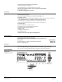
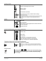
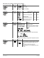
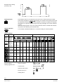
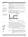
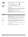
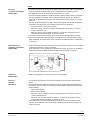
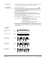
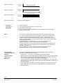
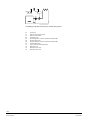
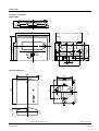
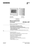
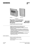
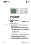
2
REV23.03RF
265
REV-R.03/1
REV23RF/SET
Self-learning Room
Temperature Controller
Receiver
REV23.03RF
REV-R.03/1
Consisting of controller (with integrated radio transmitter) and receiver
(switching unit with relay outputs)
•
•
•
•
Mains-independent room temperature controller
Straightforward, self-explanatory menu selection via roller selector
Self-learning 2-position controller providing PID mode (patented)
Choice of operating modes:
Automatic with maximum 3 heating or cooling periods, continuously comfort,
continuously economy, frost protection with one 24-hour operating mode including
one heating or cooling period
• In automatic mode, one temperature setpoint can be entered for each heating or
cooling period
• Optional control of cooling equipment
• Advantageous for retrofitting and upgrading projects
(wireless room unit)
Use
For control of the room temperature in:
• Apartments, single-family or holiday houses
• Offices, individual rooms, consulting rooms or commercially used spaces
For control of the following pieces of equipment:
• Solenoid valves of instantaneous water heaters
CE1N2265en
22.02.2006
Building Technologies
HVAC Products
•
•
•
•
•
•
Solenoid valves of atmospheric gas burners
Forced draft gas or oil burners
Circulating pumps of heating systems, zone valves
Electric direct heating systems or fans of electric storage heaters
Thermal actuators
Cooling and refrigeration equipment
•
•
•
•
Radio signal transmission
PID control with self-learning or selectable switching cycle
2-position control
Automatic mode with 7-day switching program for 24-hour, working day, weekend or
7-day operation with up to 3 heating or cooling periods per day
Each heating or cooling period has its own temperature setpoint
One 24-hour operating mode with one heating or cooling period
Override button
Sensor calibration and reset function
Frost protection or overtemperature protection
Limitation of the minimum setpoint
Holiday mode
Heating or cooling mode
Periodic pump run
Optimum start control with the first heating period
Functions
•
•
•
•
•
•
•
•
•
•
Type summary
Radio signal equipment consisting of:
Room temperature controller (transmitter), receiver (switching unit)
and support
Room temperature controller (transmitter) and support
Receiver (switching unit)
REV23RF/SET
REV23.03RF
REV-R.03/1
Ordering
When ordering, please give the type references according to «Type summary».
The controller / transmitter REV23.03RF is supplied complete with batteries.
Technical design
Display and
operating elements
2/17
Building Technologies
HVAC Products
Raumtemperaturregler REV23.03RF
CE1N2265en
22.02.2006
Operating elements
Selection of operating mode (see below)
«Warmer» button
«Colder» button
Override button (see below)
Roller selector for the menu, submenu and the settings
Confirm by pressing
Leaving the current menu level and returning to the menu level
previously active (settings currently displayed will be accepted)
Displays
Time of day
°C
Room temperature
Change batteries (display appears about 3 months before batteries are exhausted)
Holiday mode active
Selection of operating mode (only one operating mode active)
Automatic mode
Comfort mode
Economy mode
Frost protection or overtemperature protection
24-hour mode with one heating or cooling period
(heating or cooling period is individually adjustable)
Temporary change of the current setpoint temperature
(change only active until the next switching point is reached)
°C
Press the + or – button once to display the adjusted temperature setpoint. It can be readjusted in increments of 0.2 °C (max.
+/- 4 °C)
Override button
In operating modes
and
, this button can be used to manually switch
from comfort to economy temperature, or vice versa. The selection is automatically reset when the next switching point is reached or when the operating
mode is changed
3/17
Building Technologies
HVAC Products
Raumtemperaturregler REV23.03RF
CE1N2265en
22.02.2006
Menu-driven user settings: 4 main menus are available
Time of day and weekday
Main menu
Submenu
h
Settings
Current time
Current weekday
Temperature
Main menu
T
Time switch
Main menu
Default settings – heating / cooling
Submenu
Setpoint of comfort mode
19 °C
23 °C
Setpoint of economy mode
16 °C
29 °C
Setpoint frost or
overtemperature protection
5 °C
35 °C
Setpoint remote operation is
not used with this unit
(10 °C)
(30 °C)
Submenu
Settings
Selection of weekday, working day,
weekend or week
Selection of the number of heating
or cooling periods (max. 3 periods
per day)
h
Selection of the heating / cooling period’s start and end time
T
°C
Selection of the heating / cooling period’s temperature setpoint
Absence
Main menu
Submenu
Entry of holidays or periods of absence. Number
of days with economy mode setting / max. 99
days
Temperature setpoint during absence.
Default setting is 12 °C for heating and 30 °C for
cooling
4/17
Building Technologies
HVAC Products
Raumtemperaturregler REV23.03RF
CE1N2265en
22.02.2006
Menu-driven heating
engineer settings
Menu items
CAL
Settings
Sensor calibration
Setpoint limitation
Optimum start control for the first heating period
(in unit of time per 1 °C)
2-position control
PID mode, self-learning
PID mode, switching cycle 6 or 12 minutes
/
Periodic pump run off / on
Heating / cooling mode
Temperature
setpoints
In automatic operating modes, the temperature setpoints can be individually adjusted
for every comfort period and for the continuous operating modes. The temperature
setpoint of economy mode is the same in automatic and continuous operation.
Protective function
In frost or overtemperature protection mode, the room temperature is constantly monitored. If it falls (rises) below (above) the adjusted setpoint, control to the adjusted frost
or overtemperature protection setpoint
will be ensured.
24-hour operating
mode
The controller operates in 24-hour operating mode according an individually adjustable
24-hour program with 1 heating / cooling period.
To adjust heating / cooling period, select 24-hour operating mode and adjust time program and desired temperature setpoint by roller selector.
24-hour operating mode is maintained until another operating mode is selected.
Switching program
The switching program can be used as a 7-day or 24-hour program, depending on
programming. It is also possible to select one of the continuous operating modes
with which the switching program is not used.
With the 7-day program, all individual days, working days (1-5), weekend (6-7), or the
entire week (1-7) can be programmed.
For each heating / cooling period, 3 different switching patterns are available.
There is a choice of 1, 2 or 3 heating / cooling periods. For each heating / cooling period, the start time, end time and comfort setpoint are to be entered.
In between heating / cooling periods, it is always the same economy temperature setpoint that is used. This economy temperature setpoint can be adjusted on the temperature menu.
5/17
Building Technologies
HVAC Products
Raumtemperaturregler REV23.03RF
CE1N2265en
22.02.2006
22
2261Z02
°C
Example with 2 heating
periods per day
Heizphase 2
20
Heizphase 1
18
16
08
10
18
22
h
Holiday function
The holiday function is to be selected on the user menu. Set the start of the holiday
/ weekday), the duration of the holiday period and
period (day of departure /
the temperature setpoint (
). This will enable the controller to maintain the adjusted
temperature for a period of up to 99 days. Every day at midnight, the counter subtracts
one day.
When the holiday period is over, the counter reads 00, and the controller will automatically resume the operating mode selected last.
Remote operation
To be flexible, the REV23.03RF has no connection facility for remote operation.
Factory settings
Switching times
Operating
mode
Block /
weekdays
Auto
1-5
Mo-Fr
6-7
Sa-Su
Temperatures in ° C
1st
period
1st period
2nd period
2nd
period
3rd
period
3rd period
06:00 08:00 11:00 13:00 17:00 22:00 19 23 20 23 21 23 16 29
07:00 23:00
19 23
1-7
Mo-Su
00:00 24:00
19 23
1-7
Mo-Su
00:00 24:00
1-7
Mo-Su
00:00 24:00
1-7
Mo-Su
07:00 23:00
16 29
5 35
19 23
Absence
Factory settings
Heating engineer level
16 29
12 30
Setpoint limitation
Control mode
2-Point control
Optimum start control
OFF
Periodic pump run
OFF
Heating active
6/17
Building Technologies
HVAC Products
Raumtemperaturregler REV23.03RF
CE1N2265en
22.02.2006
Heating engineer level
Access
To access the heating engineer level, keep the «Warmer» and «Colder» buttons depressed and simultaneously roll the roller selector away from the display and then toward the display.
Sensor calibration
If the displayed temperature does not agree with the room temperature effectively
measured, the temperature sensor can be recalibrated (recalibration to be made on the
heating engineer level.)
The displayed temperature can be matched to the effective room temperature in increments of 0.2 °C (max. ± 2 °C).
Minimum setpoint limitation to 16 °C prevents undesired heat transfer to neighboring
apartments in buildings with several heating zones. The setting is to be made on the
heating engineer menu.
CAL
Setpoint limitation
Optimum start control
Optimization brings forward the switch-on point of the first heating period such that the
adjusted setpoint will be reached at the required time.
The setting depends on the type of controlled system, that is, on heat transmission
(type of piping system, radiators), building dynamics (building mass, insulation), and
heat output (boiler capacity, flow temperature).
Optimum start control is switched off at
Example using an actual
room temperature of 18 °C
and a setpoint of 20 °C
T
Pon
°C
20
19
T
TR x
1st heating period
2264D03
18
17
16
Start
-3 h
- 1½ h
-2h
-1h
-1h
- ½h
(slow controlled system)
- 1h
-¾ h
- ½h
- ¼h
(fast controlled system)
1/4h/°C
Optimum start controll Off
T
t
Control
t
- 4h
1/2h/°C - 2 h
1h/°C
Temperature (°C)
Forward shift of switch-on point (h)
(medium controlled system)
(no impact)
TRx
Pon
Actual valve of room temperature
Starting point of optimum start control
REV23.03RF is a 2-position controller providing PID mode. The room temperature is
controlled by the cyclic switching of an actuating device.
The controller generates the positioning signals depending on the deviation of the setpoint from the actual value acquired by the built-in temperature sensor.
The rate of response to the deviation depends on the selected control algorithm:
Self-learning mode
The controller is supplied with an active self-learning mode, enabling it to automatically
adapt to the type of controlled system (building construction, type of radiators, size of
the rooms, etc.). After a certain learning period, the controller optimizes its parameters
and then operates with the parameters it has learned.
PID 12 mode
Switching cycle of 12 minutes for normal or slow controlled systems
(massive building structures, large spaces, cast-iron radiators, oil
burners).
PID 6 mode
Switching cycle of 6 minutes for fast controlled systems (light building
structures, small spaces, plate radiators or convectors, gas burners).
Pure 2-position control with a switching differential of 0.5 °C (±0.25 °C)
for very difficult controlled systems with considerable outdoor temperature variations.
For easy commissioning controller is set to 2-Point mode as factory
setting.
2-Pt mode
7/17
Building Technologies
HVAC Products
Raumtemperaturregler REV23.03RF
CE1N2265en
22.02.2006
Periodic pump run
/
Protects the pump against seizing during longer off periods. Periodic pump run is activated for one minute every 24 hours at midnight. This function can be selected on the
heating engineer menu.
Periodic pump run active:
Operating mode
Heating / cooling
/
/ periodic pump run inactive:
The controller is suited for cooling applications.
The function can be selected on the heating engineer menu.
The controller comes set for heating operation (refer to section «Factory settings»).
User-defined data:
Press the button behind the pin opening for at least one second: This resets the userspecific settings to their default values (heating engineer settings will not be changed).
The clock starts at 12:00. During the reset time, all sections of the display are lit, enabling them to be checked.
All user-defined data plus the heating engineer settings:
Press the button behind the pin opening together with the warmer and colder buttons
for at least one second.
After the reset, all factory settings will be reloaded (also refer to section «Factory
settings»).
Mechanical design
Controller
Battery change
The REV23.03RF has a plastic housing with a large display and easily accessible operating elements. The controller is removed from its base by sliding it upward. It is thus
possible to replace the two type AA 1.5 V alkaline batteries contained in the compartment at the rear of the controller.
About 3 months before the batteries are exhausted, battery symbol
appears on
the display, but all functions are fully maintained. When replacing the batteries, the
current data will be retained for a maximum of one minute.
Receiver
REV-R.03/1
Plastic housing with easily accessible operating elements and removable cover. The
unit can be fitted to all commercially available recessed conduit boxes or directly on the
wall. A relay with a potential free changeover contact, the connection terminals and the
receiving antenna are integrated in the housing.
Base
The base can be fitted to most types of commercially available recessed conduit boxes
or directly on the wall.
Support
The support supplied with the controller enables the unit to be put on a shelf. It can be
easily fitted to the controller with no need for tools.
8/17
Building Technologies
HVAC Products
Raumtemperaturregler REV23.03RF
CE1N2265en
22.02.2006
Notes
Planning
controller / transmitter
REV23.03RF
• The room unit should be located in the main living room (on the wall or free-standing
using the support provided) while giving consideration to the following points:
• The distance to the receiver should not exceed 20 m or 2 floors
• The unit should be located such that the sensor is able to capture the room temperature as accurately as possible, without getting affected by direct solar radiation or
other heat or refrigeration sources (in the case of wall mounting, about 1.5 m above
the floor)
• The unit should be located such that it can transmit signals with as little interference
as possible. For this reason, the following points should be observed:
− Do not mount the unit on metal surfaces
− Not in the vicinity of electrical cables and equipment such as PCs, TV sets, microwave appliances, etc.
− Not in the vicinity of large metal structures or construction elements with fine
metal meshes like special glass or special concrete
• The control mode can be changed via the menu-driven heating engineer settings.
• If the room temperature displayed does not agree with the room temperature effectively measured, the temperature sensor should be recalibrated (refer to «Calibration
of sensors»).
Wall mounting of
controller / transmitter
REV23.03RF
• In the case of wall mounting, ensure that there is sufficient clearance for removing the
controller from its base, and for replacing it
First, fit the base. Then, engage the controller from the top. The base can be fitted to
most commercially available recessed conduit boxes or directly on the wall
2261Z03
min.
10 cm
Support of
REV23.03RF
• Refer to the Installation Instructions printed on the package.
Planning
Receiver
REV-R.03/1
• The receiver and switching unit should preferably be mounted near the controlled
device
• The unit should be located such that it can receive signals with as little interference
as possible. For this reason, the following points should be observed (same as with
the transmitter):
− Not in control panels
− Not on metal surfaces
− Not in the vicinity of electrical cables and equipment such as PCs, TV sets, microwave appliances, etc.
− Not in the vicinity of large metal structures or construction elements with fine
metal meshes like special glass or special concrete
• The location where the unit is mounted should be dry and free from splash water
• The unit can be fitted to most commercially available recessed conduit boxes or directly on the wall
9/17
Building Technologies
HVAC Products
Raumtemperaturregler REV23.03RF
CE1N2265en
22.02.2006
Mounting and
installation of receiver
REV-R.03/1
The receiver must be wired with the power supply switched off.
Mains voltage may be switched on again only after the unit is completely
mounted.
• When mounting the unit, the base must first be fitted and wired (L/N = AC 230 V
mains supply, LX/L1 = consumers). Then, engage the unit at the top, swing it downward and secure it with a screw
• For more detailed information, refer to the Installation Instructions supplied with the
unit
For the electrical installation, the local safety regulations must be complied with.
Commissioning
controller/transmitter
REV23.03RF
and receiver
REV-R.03/1
LED_1 (green / red):
Indication for
- Signal strength
- Receiver linked to
cotroller/transmitter
Override button and
test telegram
ESC button and
learning telegram
LED_2 (orange):
Indication for
- Learning mode
- Telegram reception
- Status of relais contact
SET button
RESET button
1. Switch on
REV23.03RF
•
Remove the battery transit tab: As soon as the battery transit tab is removed, the
unit starts to operate.
2. Mount REV-R.03/1
temporarily
•
If possible, mount receiver temporarily in a first run (e.g. double coated tape). Doing
that, location of best RF reception can be identified later on. See clause “5 Find location of best reception“
Completely wire and mount REV-R.03/1 temporarily (please also close front cover)
•
3. Link REV-R.03/1
with REV23.03RF
a) Switch on power at REV-R.03/1: LED_1 lights always in red or flashes in red
b) Press the "RESET“ button on REV-R.03/1 for about 4 seconds: The orange LED_2
will flash very fast and briefly (stored address of REV23.03RF will be erased)
c) Press the "SET“ button (set / learn) for about 3 sec. until the orange LED_2 starts
flashing slowly and continuously: Receiver is now in learning mode
d) The receiver stays max. 25 minutes in learning mode. If no learning telegram from
REV23.03RF is received during that period of time, repeat steps b) and c) again
on REV23.03RF for about 4 seconds. Learning telee) Press the ESC button
gram is transmitted
f) If REV-R.03/1 receives learning telegram, the orange LED_2 flashes fast and
briefly
g) If the orange LED_2 is steady on, the relay is energized (= controlled device ON)
h) If the orange LED_2 is dark, the relay is deenergized (= controlled device OFF)
i) Depending on the operating state, REV23.03RF repeats the ON or OFF control
telegram every 3 minutes. With this the relay will be switched ON or OFF according
to control telegram latest after 3 minutes
j) If REV-R.03/1 does not receive any correct control telegram within 60 minutes,
controlled device is being switched off and LED_1 flashes in red
k) In the event of a power failure at the REV-R.03/1, the relay will be deenergized.
10/17
Building Technologies
HVAC Products
Raumtemperaturregler REV23.03RF
CE1N2265en
22.02.2006
4. Site REV23.03RF
•
•
5. Find location of
best RF reception
a) Switch off power at REV-R.03/1
Site REV23.03RF at preferred location for mounting at wall or setting up with stand
Also refer to “Mounting and siting notes REV23.03RF and REV-R.03/1“
for
b) Switch on REV23.03RF, site at preferred location and press override button
about 4 seconds: REV23.03RF transmits test telegrams every 2 seconds.
Transmission of test telegrams stops automatically after 10 minutes or after pressing either “ESC” button or override button
c) Switch on power at REV-R.03/1
d) Observe both LEDs on REV-R.03/1 from a distance of 2…3 meters
e) Orange LED_2 must flash briefly every 2 seconds. If LED_2 does not flash every
2 seconds, distance between REV23.03RF and REV-R.03/1 is too far. Mount
REV-R.03/1 closer to REV23.03RF
f) LED_1 shows received signal strength of last telegram:
LED_1 flashes red:
Signal is too weak to get a durable link. Mount REV-R.03/1
closer to REV23.03RF
LED_1 flashes green: We distinguish between three signal strengths:
Very good (flashes 3x), Good (flashes 2x) and
Satisfactory (flashes 1x).
As soon as LED_1 flashes in green, link between
REV23.03RFand REV-R.03/1 is basically ok.
g) Move REV-R.03/1 within an area of approximately 1 square meter to find location of
best RF reception. Always observe LEDs from a distance of 2…3 meters. To get a
durable link, we recommend to site REV-R.03/1 at a location where signal strength
is at least “Good”.
6. Explanations
to LEDs
No REV23.03RF linked
LED_1 lights always
in red
Red on
LED_1 flashes in red
Red on
Red off
Signal strength too weak
Red off
LED_1 flashes
3 times in green
Green on
Signal strength: Very good
1 2 3
1 2 3
Green off
Starting
sequence
LED_1 flashes
2 times in green
Signal strength: Good
1 2
1 2
Green on
Green off
Starting
sequence
LED_1 flashes
1 time in green
Starting
sequence
Green on
Starting
sequence
Starting
sequence
Signal strength: Satisfactory
1
1
1
Green off
Starting
sequence
Starting
sequence
Starting
sequence
11/17
Building Technologies
HVAC Products
Raumtemperaturregler REV23.03RF
CE1N2265en
22.02.2006
LED_2 is always off
Orange on
Orange off
LED_2 is always on
Orange on
Orange off
Controlled device OFF
Controlled device ON
Learning mode active
LED_2 flashes always
Orange on
Orange off
LED_2 flashes briefly
Reption of control telegram
7. Finishing
mounting of
REV-R.03/1
a)
b)
c)
d)
e)
Switch off power
Mark location where REV-R.03/1 is currently fixed
If necessary loosen wiring
Mount receiver at location marked before, wire completely and close housing
Switch on mains power
Notes
•
•
In the event of a power failure at the REV-R.03/1, the relay will be deenergized.
If in normal operation REV-R.03/1 does receive for more than 25 minutes a very
weak or no control telegram from REV23.03RF, LED_1 starts to flash in red.
If control telegram is still understood correctly, receiver continues with normal operation. If control telegram is not understood anymore, relay remains in last position
being switched to before.
As soon as REV-R.03/1 does receive any correct control telegram from
REV23.03RF again, receiver continuous with normal operation
In case of error, REV-R.03/1 switches off relay approximately 60 minutes after reception of last correct control telegram. The controlled device is also switched off
and LED_1 flashes in red.
As soon as REV-R.03/1 does receive any correct control telegram from
REV23.03RF again, receiver continuous with normal operation
•
Commissioning
controller/transmitter
REV23RF
(previous model)
and receiver
REV-R.03/1
•
If instead of REV23.03RF the previous model REV23RF shall be linked with
REV-R.03/1, follow the procedure below:
− Follow steps 1 … 3b (same as commissioning with REV23.03RF)
− Instead of step 3c, press buttons SET and RESET simultaneously for approximately
3 seconds until orange LED_2 starts flashing slowly and continuously: Receiver is
now in learning mode for previous controller type REV23RF
− Change temperature setpoints at REV23RF to force transmission of a control telegram: As soon as orange LED_2 flashes fast and shortly REV23RF and REV-R.03/1
are linked together
− If the orange LED_2 is steady on, the relay is energized (= controlled device ON)
− If the orange LED_2 is dark, the relay is deenergized (= controlled device OFF)
− Continue to step 7
12/17
Building Technologies
HVAC Products
Raumtemperaturregler REV23.03RF
CE1N2265en
22.02.2006
Technical data controller / transmitter REV23.03RF
General data
controller / transmitter
Operating voltage
Batteries (alkaline AA)
Battery life
Backup for battery change
DC 3 V
2 x 1.5 V
approx. 2 years
max. 1 min
General data controller
Sensing element NTC
Measuring range
Time constant
Setpoint setting ranges
Normal temperature
Economy temperature
Frost protection setpoint
Setting range
Factory setting
Resolutions of settings and display
Setpoints
Switching times
Measurement of actual value
Display of actual value
Display of time
SRD band
Transmit frequency REV23.03RF
Max. transmitter power
Max. data throughput
Modulation
Frequency stability
Address range
(preset in the factory)
Operation
Climatic conditions
Temperature
Humidity
Transport
Climatic conditions
Temperature
Humidity
Mechanical conditions
conformity
EMC directive
R&TTE directive
NTC 10 kΩ at 25 °C ±1 %
0…50 °C
max. 10 min
General data transmitter
Environmental
conditions
Norms and standards
Product safety
Radio equipment
Automatic electrical controls for
household and similar use
Electromagnetic compatibility
Immunity
Emissions
Radio equipment
Approvals
In the following countries
5 … 29 °C
5 … 29 °C
5...29 °C
5 °C
0.2 °C
10 min
0.1 °C
0.2 °C
1 min
868.7 to 869.2 MHz
868.95 MHz
< 10 mW / typically 4 mW
19200 symbol/s = 38400 Bit/s
binary frequency changeover BFSK
< ±20 ppm (±17 kHz)
16 Bit (0...65535)
to IEC 60 721-3
class 3K3
5 ...+ 4 0 °C
< 85 % r. h.
to IEC 60 721-3
class 2K3
− 25...+70 °C
< 93 % r. h.
class 2M2
89/336/EEC
EN 301 489-3
EN 301 489-3
EN 60 730-1
EN 61 000-6-1
EN 61 000-6-3
EN 300 220-3
0359 !
all ECC countries,
Norway, Iceland and Switzerland
13/17
Building Technologies
HVAC Products
Raumtemperaturregler REV23.03RF
CE1N2265en
22.02.2006
Devices of safety class
Degree of pollution
Weight (incl. package)
II to EN 60 730-1
normal
REV23.03RF
REV23RF/SET
Color
Housing
Base
Dimensions
0.37 kg
0.68 kg
signal-white RAL 9003
grey RAL 7038
140x103x30 mm
Technical data receiver REV-R.03/1
Operating voltage
Power
Frequency
Switching capacity of relays
Voltage
Current
Environmental conditions Operation
Climatic conditions
Temperature
Humidity
Storage and transport
Climatic conditions
Temperature
Humidity
Mechanical conditions
conformity
Norms and
EMC directives
standards
Low-voltage directives
R&TTE directives
Product safety
Radio equipment
Automatic electrical controls
for household and similar use
Special requirements placed on
energy controllers
Electromagnetic compatibility
Immunity
Emissions
Radio equipment
Approval
In the following countries
General unit data
Devices of safety class
Degree of pollution
Weight (incl. package)
REV-R.03/1
REV23RF/SET
Color
Unit front
Base
Dimensions
AC 230 V +10/−15 %
< 10 VA
45...65 Hz
AC 24...250 V
6 (2.5) A
to IEC 60 721-3
class 3K3
0...+45 °C
< 85 % r. h.
to IEC 60 721-3
class 2K3
− 25...+70 °C
< 93 % r. h.
class 2M2
89/336/EEC
73/23/EEC
EN 301 489-3
EN 301 489-3
EN 60 730-1
EN 60 730-2-11
EN 61 000-6-1
EN 61 000-6-3
EN 300 220-3
0359 !
all ECC countries,
Norway, Iceland and Switzerland
II to EN 60 730-1
normal
0.24 kg
0.68 kg
Signal-white RAL 9003
grey RAL 7038
83x104x32 mm
14/17
Building Technologies
HVAC Products
Raumtemperaturregler REV23.03RF
CE1N2265en
22.02.2006
Connection diagram receiver REV-R.03/1
Lx
L
Lx
N
L1
L2
N2
L
N
Lx
L1
AC 24...250 V
AC 230 V
L
L2
M1
N2
Y1
2255A01
Nx
Live conductor, AC 230 V
Neutral conductor, AC 230 V
Live, AC 24...250 V
N.O. contact,
AC 24...250 V / 6 (2.5) A
N.C. contact,
AC 24...250 V / 6 (2.5) A
Circulating pump
Receiver REV-R.03/1
Actuating device
M1
Y1
N
Nx
Application examples
T
T
N2
F1
F2
N1
N1
N2
F2
F1
T
T
Y2
M1
T
M1
2255S02
2255S01
Y2
T
Instantaneous hot water heater
N1
T
N3
Atmospheric gas burner
T
N2
Y4
E1
Zone valve
T
N1
2255S05
Y3
2255S03
N4
N2
Cooling equipment
15/17
Building Technologies
HVAC Products
Raumtemperaturregler REV23.03RF
CE1N2265en
22.02.2006
N1
T
N2
Y1
2252S04
M1
Circulating pump with precontrol by manual mixing valve
E1
F1
F2
M1
N1
N2
N3
N4
Y1
Y2
Y3
Y4
Cooling unit
Thermal reset limit thermostat
Safety limit thermostat
Circulating pump
Room temperature controller (transmitter) REV23.03RF
Receiver REV-R.03/1
Room temperature controller (transmitter) REV23.03RF
Receiver REV-R.03/1
3-port valve with manual adjustment
Solenoiod valve
Motorized 3-port valve
Motorized 2-port valve
16/17
Building Technologies
HVAC Products
Raumtemperaturregler REV23.03RF
CE1N2265en
22.02.2006
Dimensions
30
Controller / transmitter
REV23.03RF
2265M03
140
104.5
127
12
78.8
56
Ø6
0
11.75
83.50
Receiver REV-R.03/1
84
2265M01
32
2265M02
60
104
60
©2006 Siemens Switzerland Ltd.
Building Technologies
HVAC Products
Raumtemperaturregler REV23.03RF
Subject to alteration
17/17
CE1N2265en
22.02.2006