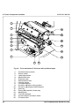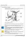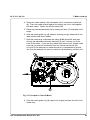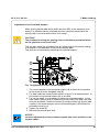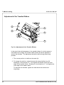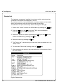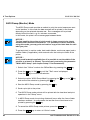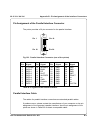
1
Thermal-direct Printer / Transfer Printer / / / Operator's Manual Edition 10/04 Gesellschaft für Computer- und AutomationsBausteine mbH & Co KG cab-Produkttechnik GmbH & Co KG Postfach 19 04 D-76007 Karlsruhe Wilhelm-Schickard-Str. 14 D-76131 Karlsruhe Telefon +49 (0) 721 / 66 26-0 Telefax +49 (0) 721 / 66 26-249 http://www.cabgmbh.com e-mail : [email protected] copyright by cab / 9008298 / O45 / 1 Angaben zu Lieferumfang, Aussehen, Leistung, Maßen und Gewicht entsprechen unseren Kenntnissen zum Zeitpunkt der Drucklegung. Änderungen sind vorbehalten. All specifications about delivery, design, performance and weight are given to the best of our current knowledge and are subject to change without prior notice. 2 cab Produkttechnik GmbH & Co KG A3-2 / A3 / A4 / A6 Thermal-direct Printer / Transfer Printer Printer Transfer A3-2 / A3 / A4 / A6 Operator's Manual All rights reserved, including those of the translations. No part of this manual nor any translation may be reproduced or transmitted in any form or by any means, for any purpose other than the purchaser's personal use, without the express written permission of cab Produkttechnik GmbH & Co KG Karlsruhe. Edition 10/04 Printed in Germany cab Produkttechnik GmbH & Co KG 3 Table of Contents A3-2 / A3 / A4 / A6 Table of Contents Trademarks .................................................................................................................................... 6 A General Guide to the Documentation ........................................................................................ 7 1. Product Description ................................................................................................................ 8 General Information .................................................................................................................. 8 Printer Types ............................................................................................................................. 9 Particular Features A3/200P, A3/300P .................................................................................... 10 Characteristics of the Thermal Printhead ................................................................................ 10 Compliances ............................................................................................................................ 11 Instructions for the Lithium Battery ........................................................................................... 11 Technical Specifications .......................................................................................................... 12 Options ................................................................................................................................... 16 External Media Unwinder/Rewinder .................................................................................. 16 Cutter Unit ........................................................................................................................ 16 Memory Card ................................................................................................................... 16 External Keyboard ............................................................................................................ 17 Interface Extensions ......................................................................................................... 17 Applicator ......................................................................................................................... 17 RFID Read-Write Unit ...................................................................................................... 17 Print Media .............................................................................................................................. 18 Print Media for Direct Thermal Printing ............................................................................. 19 Print Media for Thermal Transfer Printing ......................................................................... 19 Label / Tag Media Specifications ...................................................................................... 20 Transfer Ribbon ................................................................................................................ 21 Software .................................................................................................................................. 22 2. General Safety Instructions .................................................................................................. 23 3. Unpacking .............................................................................................................................. 23 Delivery Contents .................................................................................................................... 23 Removing the Securing Devices ............................................................................................. 24 4. Printer Component Location ................................................................................................ 25 4 5. Connecting the Printer ......................................................................................................... Connection to Power Supply ................................................................................................... Connection to a Computer ...................................................................................................... Switch on the Printer ............................................................................................................... 31 31 32 33 6. Control Panel ......................................................................................................................... Use of the Control Panel ......................................................................................................... Structure of the Control Panel ................................................................................................. Functions of the Control Panel during Printing ........................................................................ Functions of the Control Panel in the Offline Menu .................................................................. 34 34 35 36 39 7. Media Loading ....................................................................................................................... General Information ................................................................................................................ Preparation for Tear-Off Mode / Rewind Mode ........................................................................ Loading Labels ........................................................................................................................ Loading Labels from Roll ........................................................................................................ Adjustment of the Printhead Support ....................................................................................... Loading Fanfold Labels ........................................................................................................... Loading Transfer Ribbon ......................................................................................................... Adjustment of the Transfer Ribbon .......................................................................................... 42 42 43 44 44 49 50 52 54 cab Produkttechnik GmbH & Co KG A3-2 / A3 / A4 / A6 Table of Contents 8. Printer Configuration ............................................................................................................ Overview ................................................................................................................................. Local Settings ......................................................................................................................... Machine Parameters ............................................................................................................... Print Parameters ..................................................................................................................... Interfaces ................................................................................................................................ Security ................................................................................................................................... 56 56 58 60 64 68 70 9. Test Options .......................................................................................................................... Overview ................................................................................................................................. Short Status ............................................................................................................................ Status Print .............................................................................................................................. Font List .................................................................................................................................. Device List .............................................................................................................................. Printhead Profile ..................................................................................................................... ASCII Dump (Monitor) Mode ................................................................................................... Test Grid ................................................................................................................................. Label Profile ............................................................................................................................ 72 72 74 76 78 80 82 84 86 88 10. Memory Cards ....................................................................................................................... Installation and Removing the Memory Card ........................................................................... Preparing the Memory Card .................................................................................................... Writing to the Memory Card .................................................................................................... Memory Card Options in the Offline Menu ............................................................................... Overview .......................................................................................................................... Label from Card ............................................................................................................... Print Directory .................................................................................................................. Copy Memory Card .......................................................................................................... Format Card ..................................................................................................................... ASCII Dump (Card) .......................................................................................................... 90 91 92 92 93 93 94 95 96 98 99 11. External Keyboard ............................................................................................................... 100 Connecting the External Keyboard ......................................................................................... 100 Key Assignment ..................................................................................................................... 101 Special Key Functions ............................................................................................................ 101 Special Characters Available with an External Keyboard ........................................................ 102 Appendices Appendix A - Operation in Peel-off Mode .................................................................................. A-1 Components for the Peel-off Mode ......................................................................................... A-1 Preliminary Tests .................................................................................................................... A-2 Present Sensor, Peel-off Adapter, Tamp Applicator ................................................................ A-2 Appendix B - Pin Assignment of the Interface Connectors ..................................................... B-1 Pin Assignment of the RS-232 Interface ................................................................................. B-1 Interface Cable for RS-232 .................................................................................................... B-2 Pin Assignment of the Parallel Interface Connector ................................................................ B-3 Parallel Interface Cable .......................................................................................................... B-3 cab Produkttechnik GmbH & Co KG 5 Table of Contents / Trademarks A3-2 / A3 / A4 / A6 Appendix C - Error Messages / Problem Solution .................................................................... C-1 Error Messages ...................................................................................................................... C-1 Recoverable Errors ......................................................................................................... C-1 Non-Recoverable Errors .................................................................................................. C-2 Errors during System Test ............................................................................................... C-2 List of Error Messages ..................................................................................................... C-3 Problem Solution .................................................................................................................... C-7 Appendix D - Maintenance / Cleaning ....................................................................................... D-1 General Cleaning ................................................................................................................... D-1 Cleaning the Print Roller ........................................................................................................ D-1 Cleaning the Printhead ........................................................................................................... D-2 Cleaning the Label Edge Sensor A3-2/A3/A4 ......................................................................... D-3 Appendix E - Replacing Assembly Units ................................................................................... E-1 Replacing the Prinhead A3-2/A3/A4 ....................................................................................... E-1 Replacing the Prinhead A6 ..................................................................................................... E-4 Replacing the Print Roller and the Rewind Assist Roller ......................................................... E-6 Appendix F - Firmware Updates ................................................................................................ F-1 General Information ............................................................................................................... F-1 Firmware Update Using the Parallel Interface ........................................................................ F-1 Firmware Update from Memory Card ..................................................................................... F-2 Error Messages During the Firmware Update ........................................................................ F-3 Index EU - Conformity Declaration Trademarks Centronics ® is a registered trademark owned by Centronics Data Computer Corporation. Macintosh-Computer is a product of Apple Computer, Inc. Microsoft ® is a registered trademark owned by Microsoft Corporation. Bitstream ® is a registered trademark owned by Bitstream Inc. TrueType is a registered trademark owned by Apple Computer Inc. cablabel ® is a registered trademark owned by cab Produkttechnik GmbH & Co KG. 6 cab Produkttechnik GmbH & Co KG A3-2 / A3 / A4 / A6 A General Guide to the Documentation A General Guide to the Documentation This manual contains the description and usage instructions for the A3-2, A3, A4 and A6 printers. For detailed technical information on programming of the A3-2, A3, A4 and A6, a separate Programming Guide is available on request. For specific information on maintenance and repair of the printers, separate Service/ Maintenance Manuals are available. The first few chapters cover general information which is necessary for unpacking and setup of the printer, including ribbon and media loading. Chapter 5 covers the connection and usage of optional equipment that may be attached to the printer. In the appendices, additional information such as cabling specifications, error messages and problem resolution, and maintenance/cleaning instructions are included. Please take special note of the specifications for suggested print media and the references to cleaning the printer, to prevent damage, poor quality printing and avoidable failures of your printer. Every effort has been made in the creation of this manual to provide as much information as possible in a form that is both understandable and useful. We welcome your comments and suggestions regarding additions or corrections to improve future editions of this manual. NOTICE ! The figures in this manual normally show the Transfer Printer A4 ! If there are important differences between the printer types you will find a notice ! cab Produkttechnik GmbH & Co KG 7 1. Product Description A3-2 / A3 / A4 / A6 1. Product Description General Information A3-2, A3, A4 and A6 are innovative printers which may be used in either direct thermal or thermal transfer mode. They offer a high resolution with virtually an unlimited variety of printout designs. The center mounting plate is made of die-cast aluminum which makes it very robust and resistant to bending. By using 32 bit-processors from Motorola and the internal memory of 8 MB (A3-2, A3) or 16 MB (A4, A6), very long large labels (up to a length of 39 in / 1000 mm) can be printed quickly. As standard equipment, the printers have a bi-directional parallel and a serial RS-232-interface. An optional RS-422/485-interface, USB-interface or ethernet-interface can be installed. The printers auto-sense which interface is actually used. Furthermore the printers have a keyboard interface to connect a standard keyboard as well as a bar code scanner. By using a memory card it is possible to print and to enter variable data without any connection to a computer. The ranging power supply (100-240VAC) allows the printers to be used around the world without re-configuration. The operation and usage of the printers is simple and comfortable. All printer settings can be carried out with the Navigator Pad. To ease the operation the active key is marked in the several operating modes. The graphic LCD display keeps the operator constantly informed about the current status of the printer. The modular design of the printers guarantees efficient service. A special feature of the A3-2 and A3 printers is the possibility to change between the 203 dpi-printhead and the 300 dpi-printhead easily, with a minimum amount of time and effort. For the printers a wide range of optional accessories like external un- and rewinders, label/tag cutters, different peel-off modules and a tamp applicator is available. 8 cab Produkttechnik GmbH & Co KG A3-2 / A3 / A4 / A6 1. Product Description Printer Types A3-2, A3, A4 and A6 printers are available in different equipment variations: for tearing-off, internal rewinding or peeling-off the labels. Moreover A3-2, A3 and A4 printer types with different printhead resolutions are offered. This results in the following product range : Basic Devices : Printer types for tearing-off the labels : Printhead 203 dpi 300 dpi Transfer Printer A3-2/200 A3-2/300 Thermal -direct Printer A3-2/200 A3-2/300 A3 : 203 dpi 300 dpi A3/200 A3/300 A3/200 A3/300 A4 : 300 dpi 600 dpi A4/300 A4/600 A6 : 300 dpi A6/300 A3-2 : A6/300 R-Versions : Printer types for internal rewinding of the labels with internal rewinder : Printhead 203 dpi 300 dpi Transfer Printer A3-2/200R A3-2/300R Thermal -direct Printer A3-2/200R A3-2/300R A3 : 203 dpi 300 dpi A3/200R A3/300R A3/200R A3/300R A4 : 300 dpi 600 dpi A4/300R A4/600R A3-2 : - P-Versions : Printer types for peeling-off the labels with internal rewinder and dispense plate : Printhead 203 dpi 300 dpi Transfer Printer A3-2/200P A3-2/300P Thermal -direct Printer A3-2/200P A3-2/300P A3 : 203 dpi 300 dpi A3/200P A3/300P A3/200P A3/300P A4 : 300 dpi 600 dpi A4/300P A4/600P A6 : 300 dpi A6/300P A3-2 : cab Produkttechnik GmbH & Co KG A6/300P 9 1. Product Description A3-2 / A3 / A4 / A6 Particular Features A3/200P, A3/300P The P-versions of the printers are specificly developed for operation in the peel-off mode and they are equipped with dispense edge as standard. In the peel-off mode the labels are removed from the silicon liner immediately after printing, and then available in a dispense position ready for further processing. A peel-off module, for example an optional present sensor, which is attached to the printer by the peripheral connector, indicates the presence of a label, and pauses the printing process until the label is removed. After taking the label from the dispense position the next label will be printed. To guarantee a maximum of reliability in the peel-off mode the printers are additionally equipped with a pair of rollers to cause the dispense tension. NOTICE ! In the delivery state, A3 is configured in such a way, that the print speed in the peel-off mode is limited to maximum 100mm/s. When using smaller labels or supply rolls with a small outside diameter it is possible to increase the print speed for the peel-off mode. We recommend to carry out preliminary tests with speed limitation switched off (see printer configuration) ! For the other P-version printers there is no limitation of the print speed in the peel-off mode. Characteristics of the Thermal Printhead CAUTION ! The thermal printhead is the most sensitive part of your printer. Please pay special attention to the following guidelines: 1) The glass cover on the printhead must not be touched with the hand. Also, do not use sharp objects (knives, screwdrivers, etc) to clean the printhead. 2) Ensure that the printhead is properly adjusted at all times. 3) Make sure that there are no high spots or debris on your media to lodge on or damage the printhead. The label surface must be smooth. Lower grade direct thermal paper is very rough and will act like sandpaper on the head, reducing the head's lifetime. Do not use low grade stock. 4) Clean the head at each change of ribbon, or with each new roll of direct thermal media, with a special cleaning pen, or a cotton swab with isopropyl alcohol. 5) Print with the lowest possible head temperature to increase the life of the printhead. 6) When changing the printhead, first turn the power off and disconnect the power cord. Then, place a clean paper towel or tissue under the head to provide a clean surface for it to rest on. When removing the head, hold it on the sides only. Failure to observe the instructions above can lead to a reduced printhead life. 10 cab Produkttechnik GmbH & Co KG A3-2 / A3 / A4 / A6 1. Product Description Compliances The device complies with the following safety regulations : CE : The printer complies with the following safety requirements - EC Low Voltage Directive (73/23/EEC) - EC Machinery Directive (98/37/EEC) - EC Electromagnetic Compatibility Directive (89/336/EEC) FCC : The device complies with the requirements of the FCC regulations part 15 for class A computers. Under disadvantageous circumstances, the operation of these devices may cause interference with radio or TV reception, which has to be eliminated by the operator. WARNING ! This is a Class A product. In a domestic environment this product may cause radio interference in which case the user may be required to take adequate measures. Instructions for the Lithium Battery The PCB of the printer is equipped with a Lithium battery. Take necessary precautions against a possible short circuit if the battery is not fully discharged. Properly remove the battery should the printer be scrapped. cab Produkttechnik GmbH & Co KG 11 1. Product Description A3-2 / A3 / A4 / A6 Technical Specifications Printhead Printhead Type : Direct thermal or thermal transfer Printhead Model : A3-2, A3, A6 : A4 : Printhead Resolution : A3-2/200 : A3-2/300 : 203 dpi = 8 Punkte / mm 300 dpi = 11,8 Punkte / mm A3/200 : A3/300 : 203 dpi = 8 Punkte / mm 300 dpi = 11,8 Punkte / mm A4/300 : A4/600 : 300 dpi = 11,8 Punkte / mm 600 dpi = 23,6 Punkte / mm A6/300 : 300 dpi = 11,8 Punkte / mm A3-2/200 : A3-2/300 : 448 640 A3/200 : A3/300 : 832 1280 A4/300 : A4/600 : 1248 2496 A6/300 : 1920 A3-2/200 : A3-2/300 : 2,3,4,5,6,7,8 ips (50,75,100,125,150,175,200 mm/s) 2,3,4,5,6 ips (50,75,100,125,150 mm/s) A3/200 : A3/300 : 2,3,4,5,6,7,8 ips (50,75,100,125,150,175,200 mm/s) 2,3,4,5,6 ips (50,75,100,125,150 mm/s) A4/300 : A4/600 : 2,3,4,5,6,7,8,9,10 ips (50,75,100,125,150,175,200,225,300 mm/s) 2,3,4 ips (50,75,100 mm/s) A6/300 : 2,3,4,5,6,7,8 ips (50,75,100,125,150,175,200 mm/s) Number of dots/line : Print Speed : for peel-off mode : Print Width : 12 Thick film transfer printhead Thin film transfer printhead On A3 the print speed is limited to maximum 4 ips (100mm/s) as standard A3-2/200 : A3-2/300 : up to 2.2 in (56 mm) up to 2.1 in (54.2 mm) A3/200 : A3/300 : up to 4.1 in (104 mm) up to 4.25 in (108.4 mm) A4/300 : A4/600 : up to 4.15 in (105.6 mm) up to 4.15 in (105.6 mm) A6/300 : up to 6.4 in (162.6 mm) cab Produkttechnik GmbH & Co KG A3-2 / A3 / A4 / A6 Media Material : Media Type : Media Winding : Supply roll Diameter : Core Diameter : Material thickness : Weight : Material Width : Media Width : for peel-off mode : Media Height : for peel-off mode : Internal Rewinder : Core Diameter : Rewind Diameter : Label side : Transfer Ribbon Inkside : Outer Diameter : Core Diameter : Length : Width : 1. Product Description Standard Labels and Cardboard / Tags Direct Thermal, Thermal Transfer and various Synthetics including: thermal transfer plaincoated papers, vinyl, Mylar, metalized paper, non-woven fabric, fine woven fabric, thermal visible light scannable paper, infrared scannable paper, thermal ticket/tag stock, thermally sensitive plastic stock. die cut labels, continuous paper face-in or face-out on the roll up to 8.2 in (210 mm) 1.5 to 3 in (38.1-76 mm) 0.003-0.01 in (0,07-0,25 mm) 60-250 g/sqm A3-2 : 2.5 in (65 mm) A3, A4 : 4.7 in (120 mm) A6 : 7.1 in (180 mm) A3-2 : .5 to 2.3 in (12-60 mm) A3, A4 : .5 to 4.6 in (12-116 mm) A6 : 2 to 6.9 in (50-176 mm) A3-2 : 1 to 2.3 in (25-60 mm) A3, A4 : 1 to 4.6 in (25-116 mm) A6 : 2 to 6.9 in (50-176 mm) A3-2, A3, A4/300 : .2 to 39 in (5-1000 mm) A4/600 : .2 to 9.8 in (5-250 mm) A6 : .24 to 39 in (6-1000 mm) A3-2, A3, A4 : .5 to 7.9 in (12-200 mm) A6 : 1 to 7.9 in (25-200 mm) to rewind media or the liner in peel-off mode 1.5 (38.1mm) up to 5.7 in (145 mm) out in or out up to 3.1 in (80 mm) 1 in (25 mm) up to 1650 in (500 m) A3-2 : up to 2.2 in (56mm) A3, A4 : up to 4.5 in (114 mm) A6 : up to 6.5 in (165 mm) Media Edge Sensor Distance to paper edge : A3-2 : .16-.32 in (4-8 mm) A3, A4, A6 : .16-2.3 in (4-57,5 mm) Material recognition : Gap sensor ("see-through"), Bottom-reflective sensor for black marks cab Produkttechnik GmbH & Co KG 13 1. Product Description Electronics Processor : Internal Memory (RAM) : Slot for memory card : Real time clock : Control panel : Interfaces Standard : serial : parallel : USB (Master) : peripheral connection : Optional : serial : USB (Slave) : Ethernet : Twinax/Coax Converter : Contents of the Print Image Text Fields : Graphic Elements : Bitmap Graphics : Barcode Fields : Fonts Available Fonts : Character Sets : Font Size : Bitmap fonts : A3 -2, A3 : 32 Bit Motorola Coldfire / 64 MHz A4, A6 : 32 Bit Motorola Coldfire / 144 MHz A3-2, A3 : 8 MB A4, A6 : 16 MB CompactFlash Type 1 up to 512 MB Printout of time and date Navigator Pad with the active key illuminated indicating operating mode Lighted graphic LCD display LCD can be set to display in different languages RS-232 8 Bit; 1,200-230,400 Baud Centronics bi-directional (IEEE 1284 Nibble mode) for keyboard / scanner / external control panel for cutter / present sensor / peel-off adapter, pause adapter / RS-422/485 8 Bit; 1,200-230,400 Baud for PC connection 10/100 Base T for IBM connection max. 250 max. 200 max. 128 (100 several graphics in memory) max.100 5 Bitmap fonts incl. OCR-A and OCR-B 3 scaleable fonts (TrueType) internal Additional TrueType fonts may be downloaded Windows : 1250 bis 1257 DOS 437, 737, 775, 850, 852, 857, 862, 864, 866, 869 EBCDIC 500, ISO 8859-1 bis -10, ISO 8859-13 bis -16, Macintosh Roman, DEC MSC, KOI8-R, Win OEM 720, UTF-8 Font style : Width and height .04 to .1 in (1 - 3 mm) Width and height are selectable up to 10. Width and height .035 to 5 in (.9 - 128 mm) Width and height are individually changeable. reverse, bold, italic, underlined, outlined, grey, vertical Font rotation : Bitmap fonts : Scaleable fonts : 0°, 90°, 180°, 270° 360° in 1° increments Scaleable fonts : 14 A3-2 / A3 / A4 / A6 cab Produkttechnik GmbH & Co KG A3-2 / A3 / A4 / A6 Graphics Graphic elements : Graphic file types : Barcodes Lineare Codes : 2-D Codes : Control / Test 1. Product Description line, box, circle, ellipse, fill-in segment, arrow .PCX, .IMG, .BMP, .TIF, .GIF and .MAC Graphic files Code 39, Code 93, Code 128 A,B,C, Codabar, EAN 8, EAN 13, EAN 128, EAN/UCC 128, EAN/UPC Anhang 2, EAN/UPC Anhang 5, FIM, HIBC, Interleaved 2/5, Ident-/Leitcode der Deutschen Post AG, Jan 8, Jan 13, MSI, Plessey, Postnet, RSS 14, UPC A, UPC E Aztec, Codablock, Data Matrix, PDF417, Micro PDF, UPS Maxicode, QR-Code Bar code height, module width and ratio are variabe, with/without check digit, human readable character, start/stop character Control : Ribbon available Paper / fanfold available Printhead closed Test options : System test when powering on including a printhead test short status, status print, font list, device list, printhead profile, label profile, test grid, ASCII dump mode Status messages : Counter of the printed length, counter of the operating hours Software Windows driver : 95, 98, ME, 2000, XP, NT from Version 4.0 cablabel : As Lite free version in the delivery contents With Advanced, Professional und Expert versionen für complex labels Others Dimensions : A3-2 : H: 10.8 in (274mm) W: 7.5 in (190mm) D: 17.6 in (446mm) A3, A4 : H: 10.8 in (274mm) W: 9.5 in (242mm) D: 17.6 in (446mm) A6 : H: 10.8 in (274mm) W: 11.9 in (302mm) D: 17.6 in (446mm) Weight : A3-2 : 19 lb. (8.5 kg) A3, A4 : 20 lb. (9 kg) A6 : 29 lb. (13 kg) Operating Voltage : 100-240 V A.C. / 50-60 Hz Maximum Power Input : A3-2, A3 : A4, A6 : Environment : Operation : Transport : Storage : 250 W 500 W at 50° to 95° F (10 to 35°C) at a humidity of 30 to 85% at -13° to 158° F (-25 to +70°C) at a max. humidity of 95% non-condensing at 41° to 104° F (5 to 40 °C) at a humidity of 5 to 85% cab Produkttechnik GmbH & Co KG 15 1. Product Description A3-2 / A3 / A4 / A6 Options External Media Unwinder/Rewinder For operating large print jobs, external unwinders and rewinders are available to handle big label rolls : A3-2 A3 A4 A6 Ext. Rewinder ER1 (up to diam. 8.3in/210mm) x x x - Ext. Rewinder ER2 (up to diam. 8.3in/210mm) - - - x Ext. Rewinder ER4 (up to diam. 11.8in/300mm) x x x - Ext. Rewinder ER6 (up to diam. 11.8in/300mm) - - - x Ext. Unwinder EU4 (up to diam. 11.8in/300mm) x x x - Ext. Unwinder EU6 (up to diam. 11.8in/300mm) - - - x Cutter Unit With the cutter unit installed, labels or continuous media may be cut when desired. Cutter options include a choice of: after each label, after a specific quantity of labels, or at the end of a print job. For cutter operation, the printer firmware will extend the label for cutting based on specified displacements, then automatically backfeed the label, so that after making a cut, the label roll will be repositioned and ready for printing the next label. The cutter is powered directly by the printers peripheral connector. A3-2 A3 A4 A6 Cutter CU2 x - - - Cutter CU4 - x x - Cutter CU6 - - - x Memory Card The printer includes an option for using memory cards in order to permanently store graphics, fonts or whole label formats. The data can be downloaded via any of the printers data interfaces. CompactFlash Type 1 cards with a maximum capacity of 512 MB are accepted. Using a memory card, the printer can be operated without being connected to a computer which represents a great advantage regarding the flexibility. 16 cab Produkttechnik GmbH & Co KG A3-2 / A3 / A4 / A6 1. Product Description External Keyboard The keyboard connector allows you to connect your printer to an USB keyboard. This will allow you to input variable data to a format stored on a memory card. Interface Extensions The printer is equipped with a slot to connect an additional interface. It is possible to install a RS-422/485 interface, an USB interface or an ethernet interface allowing the printer to be connected to several different types of interfaces and networks. Applicator The applicator A 1000 represents, in combination with the P-versions of A3-2, A3 and A4, the inexpensive solution both for the semi-automatic labeling and for the integration into automated production lines. RFID Read-Write Unit The A3 and A4 could be supplied with a factory installed RFID Read-Write Unit 13.56 MHz with Ethernet for the marking of smart labels. cab Produkttechnik GmbH & Co KG 17 1. Product Description A3-2 / A3 / A4 / A6 Print Media The A3-2, A3, A4 and A6 printers can be run in a direct thermal or thermal transfer mode. For direct thermal mode, the label material must be specifically designed for this use. The printout is created directly on the paper, as the paper reacts with the heat of the printhead and results in the darkening of the material. Driving the printer in thermal transfer mode requires standard paper labels and the addition of thermal transfer ribbons. The printout is created by heating the ribbon with the printhead, resulting in a transfer of color from the ribbon onto the labels. The printers allow for regulating the required heat setting through the software, which offers a wide range of printing possibilities. A3-2, A3, A4 and A6 are able to print on labels and continuous media, with a maximum supply roll diameter of 8.2" (210 mm). The minimum core diameter is 1.5" (38.1mm). Top of form (label edge) detection is accomplished with a moveable photocell, which is driven by the internal processor of the printer. The photocell does an automatic measurement of the used material. No additional adjustments are required. The following pages contain more detailed information and specifications which apply depending on the print method to be used. For information of specific materials you may wish to use, check with your local distributor. Not every material is suitable for quality direct thermal or thermal transfer printing. The surface of the material is very often the main factor, but not the only factor determining suitability. There are many materials available for labeling and your local distributor can offer suggestions to meet your particular needs. 18 cab Produkttechnik GmbH & Co KG A3-2 / A3 / A4 / A6 1. Product Description Print Media for Direct Thermal Printing The material to be printed must comply with certain important specifications to ensure a quality print image and to avoid damage or extra wear to the printhead. Using the label stock which we have tested and recommended ensures the best treatment of the printhead. In the event that your label stock will be supplied by another manufacturer, the following points should be noted with regard to the use of thermal paper: 1. The surface coating/quality must sufficiently cover the thermo-reactive coating to ensure that the printhead does not become damaged. If the surface coating is too thin, the printhead can become pitted due to microscopically small "explosions" resulting when the chemical reaction of the thermal coating takes place. The result is that the printhead can rapidly become damaged. 2. The surface of the label should be very smooth to avoid a "sandpaper" type effect on the printhead. 3. Choose label stock which can be printed with the lowest possible thermal value. The greater the thermal value required, the greater wear on the printhead. Additionally, when the thermal value is high, the time required for the printhead to heat up and cool down can have an adverse effect on the quality of print, especially when a fast print speed is desired. Print Media for Thermal Transfer Printing The thermal transfer process makes possible the use of many different materials for printing, such as normal paper, cardboard, polyester film, etc. NOTICE ! The print results depend to a great degree on a suitable combination of label material and transfer ribbon. The label surface dictates which transfer ribbon will provide the best print results, and which ribbon cannot. An unsuitable match of label material to ribbon type can be responsible for an extremely poor print quality. Your Dealer can give you expert advice as to which combination of materials will best meet your requirements. Your Dealer can also assist you by testing the different materials you may be considering for your labeling needs. cab Produkttechnik GmbH & Co KG 19 1. Product Description A3-2 / A3 / A4 / A6 Label / Tag Media Specifications Label and tag media to be used by the printer must conform to the following specifications: G H K E I D A L C B M F Fig. 1 Media Specifications Item A A3-2 Label width Peel-off mode .5 - 2.3 (12-60) 1 - 2.3 (26-60) A3 A4 A6 .5 - 4.6 (12-116) .5 - 4.6 (12-116) 2 - 6.9 (50-176) 1 - 4.6 (25-116) 1 - 4.6 (25-116) 2 - 6.9 (50-176) B Backing width 1 - 4.5 (25-65) 1 - 4.7 (25-120) C Label length *A4/600 Peel-off mode .2 - 39 (5-1000) .2 - 39 (5-1000) 1 - 4.7 (25-120) D Gap between labels E Label thickness .003 - .01 (0.07-0.25) 2 - 7.1 (50-180) .2 - 39 (5-1000) .24 - 39 (6-1000) *.2 - 9.8 (5-250) .5 - 7.9 (12-200) .5 - 7.9 (12-200) .5 - 7.9 (12-200) 1 - 7.9 (25-200) .08 - 39 (2-1000) F Thickness of backing material .003 - .01 (0.07-0.25) G Distance of the first printing position from the edge of the backing paper .08 (2) H Distance of the label sensor from the edge of the backing paper I Width of the perforation mark >.2 (>5) K Height of the perforation mark .08 - .4 (2-10) L Width of the reflective mark (black) >.2 (>5) M Height of the reflective mark (black) .08 - .4 (2-10) .16 -.32 (4-8) .1 (2.5) .16 - 2.3 (4-57.5) Table 1 Media values are displayed in inches (values in brackets are mm) 20 cab Produkttechnik GmbH & Co KG A3-2 / A3 / A4 / A6 1. Product Description Transfer Ribbon The choice of transfer ribbon plays an important role in the quality of print image that can be produced, and it also directly affects the longevity of the printhead. CAUTION ! Poor quality transfer ribbon can lead to premature deterioration of the printhead ! The ribbon material must be as anti-static as possible. This is because the extremely thin surface coating on the printhead can be damaged by a build up of electrostatic charges. The temperature tolerance of the material must be extremely high in order to avoid the transfer ribbon melting directly onto the printhead. The temperature increase which results from the printing cycle must be dissipated over the label and the transfer ribbon. Poor quality transfer ribbon often has only a limited ability to dissipate the heat. This can contribute to overheating of the printhead, despite electronic protection against overheating Poor quality transfer ribbon also tends to partially shed its ink coating, causing the printhead and sensors to accumulate dirt. In addition, with some transfer ribbons, the back coating can flake or smudge, leaving traces on the printhead. All of these effects contribute to lowering the print quality to below desired standards. Numerous tests have been conducted with a very large number of different transfer ribbons and we recommend only ribbons supplied by reputable manufacturers. A variety of different transfer ribbons can sometimes be used for a particular type of label stock. The quality of print is determined by the correct combination of these materials. NOTICE ! When choosing material, make sure the transfer ribbon is slightly wider than the width of the label backing. The presence of transfer ribbon is sensed by the rotational movement control of the transfer ribbon unwinder, rather than with photocell sensors. As a result, ribbons that have a thinner coating or those with a colored coating can be used without problems. The possiblity of printing labels up to the absolute end of the ribbon is restricted by the length of the uncoated "trailer", which attaches the end of the ribbon to the core. NOTICE ! Make certain before purchasing transfer ribbon that the "trailer" (see above) is not more than 2.3in (60mm) long. cab Produkttechnik GmbH & Co KG 21 1. Product Description A3-2 / A3 / A4 / A6 Software There are several methods to create formats and to send them to the printer. Below, a short explanation of the most common methods is given. Direct Programming The printer is equipped with an internal command set. The command set is designed to program all functions of the printer. To create a label format, use any ASCII editor to combine the necessary commands. Save the commands to a file, then copy the file to the printer using the connected interface and HyperTerminal or the DOS COPY command. Direct programming requires a minimum knowledge of programming logic. The printer commands are designed logically and structured clearly. However it is necessary to carry out several test prints when creating a label using the command set since no image of the label is displayed on the monitor. The complete description of the command set and sample programs is available in the "Programming Guide cab Printers". Windows Printer Driver Windows Printer drivers are available for the different Windows versions. You can get these drivers from your distributor or from the web. Visit the appropriate website listed on page 2 to download the drivers. The printer can be operated from any Windows Application that supports Windows Printer drivers using the Windows Printer driver. The graphical user interface allows for easier creation of label formats. However, the functionality depends on the choosen application and how each product supports Windows Printer drivers. There could be restrictions depending on the application you are using. A help file is included with the drivers to explain the usage and limitations when using certain Windows applications. Label Software There are several Windows Applications that are designed to create labels. These programs are more suited to the requirements of label printing than standard Windows Applications. In some cases these programs use the Windows Printer Driver. Some applications, for example cablabel, have integrated internal drivers to operate the printers of the A series. These applications offer the best solution for creating and printing labels. 22 cab Produkttechnik GmbH & Co KG A3-2 / A3 / A4 / A6 2. General Safety Instructions / 3. Unpacking 2. General Safety Instructions CAUTION ! - - The printer is built exclusively to print die-cut labels, continuous media, and similar materials as listed in Technical Specifications in Chapter 1. Connect the printer to an outlet with the correct voltage! The printer is configured for voltages of 100 to 240 V. Connect only to a power outlet with a grounded contact. The printer must only be connected to devices which have extra low voltage. Power must be OFF before plugging in any accessory, connecting to a computer and before performing any maintenance on the printer. Also turn the power off on all appliances before disconnecting from the printer. Do not expose the printer to any moisture, or use in damp or wet areas. The printer will operate with the cover open if necessary. This is not recommended, as it might allow debris to collect on the printhead surface. If the printer must be operated with the cover open, extra care must be taken to avoid allowing hair, jewelry, clothing, etc. near the moving parts. During the print process the printhead will become hot. Use extra caution when touching the printhead. Do not touch the printing surface of the printhead with you hand! Any adjustments or repairs which are not described in this manual, should only be carried out by an authorized service technician. WARNING ! To avoid possible electric shock, do not open the backside cover! 3. Unpacking Delivery Contents Please inspect the printers packaging and contents immediately after receipt for possible damage during shipment. NOTICE ! Be sure to preserve the original packaging for possible later shipment! The shipping container will contain the following standard components: - Thermal Transfer Printer Cardboard Core for the transfer ribbon rewinder Tear-off Plate (Basic devices only) Rewind Guide Plate (R-Versions only) Dispense Plate (P-Versions only) Power Cord Documentation cab Produkttechnik GmbH & Co KG 23 3. Unpacking A3-2 / A3 / A4 / A6 Removing the Securing Devices 1 2 Fig. 3 Removing the securing devices 1. Place the printer on a solid flat surface. 2. Open the cover. 3. Remove the securing devices (1, 2). 24 cab Produkttechnik GmbH & Co KG A3-2 / A3 / A4 / A6 4. Printer Component Location 4. Printer Component Location 11 10 9 1 8 2 3 4 5 6 7 Fig. 4a General view 1 2 3 4 5 6 7 8 9 10 11 - Warning label ''End of Ribbon'' Control panel Present sensor (Option for P-Version) Print mechanism Internal rewinder (P- and R-Versions only) Ribbon take up hub Ribbon supply hub Media hub Media Retainer Warning label ''End of Paper'' Cover cab Produkttechnik GmbH & Co KG 25 A3-2 / A3 / A4 / A6 4. Printer Component Location 1 2 8 9 3 4 10 5 11 6 12 7 13 Fig. 4b Print mechanism Basic Devices with printhead open 1 2 3 4 5 6 7 8 9 10 11 12 13 26 - Printhead locking screw Ribbon shield Label edge sensor Media feed roller Tear-off plate Printhead support Screw to adjust the printhead support Printhead lever Screw to adjust the ribbon shield Thermal printhead Media guide Swing (A3-2 and A3: Guide axle) Allen Key cab Produkttechnik GmbH & Co KG 4. Printer Component Location A3-2 / A3 / A4 / A6 1 2 8 9 3 4 10 5 11 6 12 7 13 Fig. 4c Print mechanism R-Versions with printhead open 1 2 3 4 5 6 7 8 9 10 11 12 13 - Printhead locking screw Ribbon shield Label edge sensor Media feed roller Rewind guide plate Printhead support Screw to adjust the printhead support Printhead lever Screw to adjust the ribbon shield Thermal printhead Media guide Swing (A3-2 and A3: Guide axle) Allen Key cab Produkttechnik GmbH & Co KG 27 4. Printer Component Location A3-2 / A3 / A4 / A6 1 2 16 3 15 4 14 5 6 13 7 12 8 11 9 10 Fig. 4d Print mechanism P-Versions with printhead open 1 2 3 4 5 6 7 8 9 10 11 12 13 14 15 16 28 - Printhead locking screw Ribbon shield Label edge sensor Media feed roller Dispense plate Rewind assist roller Locking system Printhead support Screw for adjusting locking system Screw for adjusting printhead support Allen key Swing (A3-2 and A3: Guide axle) Media guide Thermal printhead Screw to adjust the ribbon shield Printhead lever cab Produkttechnik GmbH & Co KG A3-2 / A3 / A4 / A6 4. Printer Component Location 3 4 1 5 2 Fig. 4e Control panel 1 2 3 4 5 - Display Navigator pad with keys Memory card LED Memory card slot Memory card ejection lever cab Produkttechnik GmbH & Co KG 29 4. Printer Component Location A3-2 / A3 / A4 / A6 1 2 3 4 5 6 Fig. 4f Back view 1 2 3 4 5 6 30 - Slot for the additional interface card (RS-422/485, ethernet or USB-slave) - Bi-directional parallel interface - USB master interface for keyboard or scanner - RS-232-interface - Power switch - Power supply connector cab Produkttechnik GmbH & Co KG A3-2 / A3 / A4 / A6 5. Connecting the Printer 5. Connecting the Printer CAUTION ! Make sure the printer is located where the unit or the operator cannot come in contact with water. Otherwise it could cause damage to the printer. Connection to Power Supply The printer is equipped with a wide range power unit (100-240V~), so it is possible to use the printer both with a voltage of 230V~/50 Hz and with a voltage of 115V~/60 Hz without making changes to the printer. CAUTION ! Make sure the power switch (1) is in position "O" (OFF) before connecting the printer to a power supply ! 1 2 Fig. 5a Power supply Insert the power cable supplied in the accessories carton into the power supply connector (2) and contact the cable to a grounded outlet. cab Produkttechnik GmbH & Co KG 31 5. Connecting the Printer A3-2 / A3 / A4 / A6 Connection to a Computer As standard, the printer is equipped with a bi-directional parallel interface (3) and a serial RS-232-interface with a 9 pin connector (4). 3 4 1 2 Fig. 5b Computer connection For connection to the parallel interface use a suitable parallel interface cable (1). Cables for the serial connection (2) are described in appendix B. You can also find descriptions of the pin assignments for the interface connectors NOTICE ! For serial connection, make sure the serial interface RS-232 of the printer is correctly configured to the settings of your computer (see printer configuration section). Connect the computer and the printer with a suitable cable and secure the cable connections with screws provided on the connectors. CAUTION ! Make sure that all connected computers and their connecting cables are correctly grounded. Information for the optional interfaces (RS-422/485, ethernet, USB) can be found in the documentation for the respective interface. 32 cab Produkttechnik GmbH & Co KG A3-2 / A3 / A4 / A6 5. Connecting the Printer Switch on the Printer 1 Fig. 5c Switch on the printer After making all connections, power on the printer using the power switch (1). The printer will perform a short system test, then display "ONLINE" on the front panel LCD. If a hardware failure occurs during the system test, the symbol and a description of the failure will be displayed on the LCD. In this case the printer should be powered off and on again. If the failure re-occurs, call for service. cab Produkttechnik GmbH & Co KG 33 6. Control Panel A3-2 / A3 / A4 / A6 6. Control Panel Use of the Control Panel The control panel allows the operator the ability to control the operation of the printer in various ways. Uses of the control panel : - to control the current print job, e.g. to pause and continue or to cancel print jobs on demand. to set print parameters, for example the heat level, the print speed, the baud rate of the serial interface, the language or the time. to execute self test functions of the printer. to operate the printer using a memory card without having a computer connected. to carry out an update of the printer's firmware. Several functions and settings can also be configured by sending printer commands from software or through direct programming. The settings configured by the control panel are basic settings. Parameters can be set on/off for all print jobs, for example "Transfer print on/ off" or the setting can be set by software for single print jobs. Parameters such as "Printhead position", which determines the position of the print image, can be set for all print jobs. Any setting that has both a front panel setting and software command, the values are totaled together for printing. In the case of On/Off settings, the software commands will override the front panel setting. The section "Printer Configuration" will indicate whether it is possible to change the settings of the front panel via software. NOTICE ! Whenever possible, use the software command during print jobs to control the printer's settings. 34 cab Produkttechnik GmbH & Co KG 6. Control Panel A3-2 / A3 / A4 / A6 Structure of the Control Panel Online 1 2 Fig. 6a Control Panel The control panel consists of a graphic display (1) and the Navigator Pad (2) with four integrated keys. The control panel display constantly provides the operator with realtime information concerning the current printer mode and label processing. The function and operation of the keys depends on the current mode. The available functions are marked by illuminating the valid symbols and text in the keys. cab Produkttechnik GmbH & Co KG 35 6. Control Panel A3-2 / A3 / A4 / A6 Functions of the Control Panel during Printing Fig. 6b Navigator Pad during Printing During printing the keys on the Navigator Pad are illuminated to indicate what functions control the print jobs. The exact key functions in the different system modes are described below. The text is not illuminated when the keys have no function in the current mode. System Mode ONLINE The printer is switched ON and ready to receive data. The display shows the time and the word "Online". During the transfer of data a rotating symbol appears on the display. When saving data on the PC card the symbol appears on the display. Key 36 Description Function on Switches to OFFLINE mode. on Performs a label feed. (on) Repeats the print of the last label, after the previous print job has been completed. (Only when setup parameter "Pause reprint" is on.) (on) Clears internal memory of the previous print job. "Pause reprint" is no longer available. cab Produkttechnik GmbH & Co KG 6. Control Panel A3-2 / A3 / A4 / A6 System Mode PRINT The printer is currently processing an active print job. In this mode, the transfer of data is possible. New print jobs will be carried out immediately following the completion of the previous job. The display shows the message "Printing label" and the current number of printed labels. Key Description Function on Interrupts the current print job on Short press Long press - cancels the current print job - cancels the current print job and deletes all jobs contained in the internal memory System Mode PAUSE The printing process is temporarily interrupted by the operator. The display shows "Pause" and the symbol Key Description appears. Function on Continues the print job on Short press Long press - cancels the current print job - cancels the current print job and deletes all jobs contained in the internal memory System Mode POWERSAVE If the printer does not receive a print job or the front panel has not been accessed for a period of time, the printer will switch into a powersave mode. During powersave mode, certain functions such as the background lighting of the display are powered off. The display shows . The illumination of the keys is switched off. To leave this mode press any key or send a print job. cab Produkttechnik GmbH & Co KG 37 6. Control Panel A3-2 / A3 / A4 / A6 System Mode FAULT-CORRECTABLE The printer has encountered a fault during printing which is easily corrected by the operator (e.g. "Out of paper"). Once the fault has been corrected, the printing process may be continued. appears on the display. Additionally, the type of fault and the The symbol total of the remaining labels is also displayed. Key Description flashes on Function Continues current print job after fault correction Short press Long press - cancels the current print job - cancels the current print job and deletes all jobs contained in the internal memory System Mode FAULT-IRRECOVERABLE During printing, a fault has occured which cannot be cleared by the operator without canceling the current print job. The symbol Key appears on the display and the type of the fault is displayed. Description flashes 38 Function Short press Long press - cancels the current print job - cancels the current print job and deletes all jobs contained in the internal memory cab Produkttechnik GmbH & Co KG A3-2 / A3 / A4 / A6 6. Control Panel Functions of the Control Panel in the Offline Menu The Offline Menu contains options to set machine and print parameters, to enter test and service functions as well to operate with the memory card. To enter this mode press the key while in the ONLINE mode. If a memory card is installed the display shows "Memory card". Otherwise "Test" will be displayed. Online [Memory card] Label from card Print directory Copy memory card * Format card * ASCII dump (Card) Test Short status Status print Font list Device list Printhead profile ASCII Dump Mode Test grid Label profile Setup * Local settings Machine parameter Print parameter Interfaces Security Service Firmware upd. * Menus and options marked with * can be protected by a PIN from unauthorized access. Functions marked with [...] are only accessible, if an optional device has been installed. Table 6 Structure of the Offline Menu cab Produkttechnik GmbH & Co KG 39 6. Control Panel A3-2 / A3 / A4 / A6 Fig. 6c Navigator Pad in the Offline Menu After switching from the "Online" mode into the Offline Menu the function of the keys are changed. Now the keys of the Navigator Pad have the function of cursor keys. Key Function - Move up in the menu - Increase numeric values - Move down in the menu - Decrease numeric values 40 - Switch to a secondary menu Move the cursor to the right during numeric settings Finish a setting with confirmation of the selected settings Start of a selected test or service function - Return from a secondary menu Move the cursor to the left during numeric settings Finish a setting with rejecting the selected settings At the start of the menu, return to the system mode "Online" cab Produkttechnik GmbH & Co KG A3-2 / A3 / A4 / A6 6. Control Panel Fig. 6d Display during selection of a function During selection of the test and service functions the display shows the selected menu. A graphic symbol accompanies the text. In the "Setup" menu, the display shows the selected parameter and the current setting of the parameter. appears in the upper line, the symbol indicates that it is If the symbol possible to switch between several parameters by pressing the key. key and the Fig. 6e Display during selection of a parameter To change the current setting press the key. Then the symbol is shown in the bottom line of the display indicating that it is possible to change the setting of the parameter by pressing the key and the key. Fig. 6f Display during change of a parameter cab Produkttechnik GmbH & Co KG 41 7. Media Loading A3-2 / A3 / A4 / A6 7. Media Loading General Information 1. Pay attention to the specifications of the material indicated in chapter 1 . 2. When using the printer for the first time or using label media with a different width, make sure to adjust the printhead support as well as the position of the label edge sensor. 3. There are warning labels on the media hub and on the ribbon supply hub which will be visible if the material is getting low. When these warning labels are visible, prepare to replace the material soon. 1 2 - Warning label "End of Ribbon" Warning label "End of Paper" 4. If you do not use the printer for an extended period of time, lift the printhead to avoid possible flattening of the print roller. 5. If you want to move or ship the printer to another location, remove the media and the ribbon from the printer. 1 2 Fig. 7a Warning labels 42 cab Produkttechnik GmbH & Co KG A3-2 / A3 / A4 / A6 7. Media Loading Preparation for Tear-Off Mode / Rewind Mode The R-version printers are delivered with the rewind guide plate (1) mounted for operation in rewind mode. With the optional tear-off plate the printer also may be operated in tear-off mode. For this purpose the rewind guide plate (1) must be replaced by the tear-off plate (3). The P-version printers are prepared for the dispense mode. After mounting the optional tear-off or rewind guide plate the printers also may be operated in tearoff or rewind mode. 2 2 1 3 Fig. 7b Exchange Rewind Guide Plate / Tear-Off Plate The exchange of the different plates can be made in a similar way as the exchange rewind guide plate / tear-off plate : 1. Open the cover. 2. Loosen the two screws (2). 3. Slide the rewind guide plate (1) to the right as far as possible to remove the plate from the printer. 4. Place the slotted holes on the tear-off plate (3) over the screws (2) on the front of the printer and slide the plate to the left until it stops. 5. Tighten the two screws (2). cab Produkttechnik GmbH & Co KG 43 7. Media Loading A3-2 / A3 / A4 / A6 Loading Labels Loading Labels from Roll 12 1 11 2 10 9 3 8 4 5 6 7 Fig. 7c Label Loading in Tear-off Mode 1. Open the cover (1). 2. Loosen the knurled screw (10), swing the media retainer (11) upwards and slide it out as far as possible. If you are using material with the same width as the previous material, just swing the media retainer (11) upwards. 3. Place the media roll (8) onto the media hub (9) and unwind a strip of media (4) from the roll. When operating in the rewind or peel-off mode make sure that the strip is long enough to reach the internal rewinder by guiding the strip through the whole print mechanism and underneath of it. Make sure that the labels between the media hub and the print mechanism are facing up. Slide the roll onto the media hub (9) until its stops. 44 cab Produkttechnik GmbH & Co KG A3-2 / A3 / A4 / A6 7. Media Loading 4. Swing the media retainer (11) downwards until it touches the media hub (9). Push the media retainer against the supply role until it rests against the label media. Tighten the knurled screw (10). 5. Raise the printhead assembly (2) by rotating the lever (7) clockwise until it stops. 6. Slide the media guide ring (6) outward, allowing enough clearance for the label stock's width when loaded. 7. Slide the media strip underneath the swing (5 /A3-2 and A3: axle) and through the adjustable photocell assembly (3) until it comes out of the front of the printer. If you are using labels that are wound-in, please make sure that you slide the media strip over the internal rewind hub (13). In figure 7d the feed path for labels wound-out is represented by a solid line, and the feed path for wound-in labels is represented by a broken line. 13 Fig. 7d Feed path in Tear-off Mode 8. Slide the media guide ring (6) inward until it lightly touches the side of the media strip. cab Produkttechnik GmbH & Co KG 45 A3-2 / A3 / A4 / A6 7. Media Loading 7 3 14 15 Fig. 7e Adjustment of the Label Edge Sensor 9. To accommodate a variety of print jobs, the position of the label edge sensor (3) can be adjusted until it is at the proper sensing position. It is important to ensure that the sensor (14) itself (the position of which is indicated by a notch in the sensor housing) is positioned so that the space between the labels can be recognized by the photocell. In the case of labels which have an unconventional shape (ie. not square or rectangular), the photo cell should be positioned at the leading edge of the label. Adjustment of the sensor is performed by sliding the handle (15) in and out. 10. Lower the printhead by rotating the lever (7) counter-clockwise until it locks. 11. When the printer is operated in rewind mode continue with point 12. When the printer is operated in peel-off mode continue with point 13. 46 cab Produkttechnik GmbH & Co KG A3-2 / A3 / A4 / A6 7. Media Loading 16 4 17 13 18 Fig. 7f Loading Labels from Roll in Rewind Mode 12. In rewind mode, the rewind guide plate (16) must be mounted. Remove the labels from the first 4 in (100mm) of the label strip. Then, slide the media strip (4) around the rewind guide plate (16) to the internal rewind hub (13) as shown in figure 7f. Slide the strip under the clamps (17) that are located on the internal rewind hub (13). Hold the internal rewind hub (13) and rotate the nut (18) counter-clockwise until it is tight. The media strip will now be fastened to the internal rewind hub (13). Rotate the internal rewind hub (13) counter-clockwise to tighten the media strip. cab Produkttechnik GmbH & Co KG 47 7. Media Loading A3-2 / A3 / A4 / A6 19 20 21 22 23 24 25 17 13 18 Fig. 7g Loading Labels from Roll in Peel-off mode 13. For peel-off mode swing the locking system (21) away from the rewind assist roller (23). 14. Remove all labels from the media strip hangig out of the printer. Then, slide the strip (25) around the dispense plate (19) to the internal rewind hub (13) as shown in figure 7g. Slide the strip under the clamps (17) that are located on the internal rewind hub (13). Hold the internal rewind hub (13) and rotate the nut (18) counter-clockwise until it is tight. The media strip will now be fastened to the internal rewind hub (13). Rotate the internal rewind hub (13) counter-clockwise to tighten the media strip. 15. Loosen the screw (22) using the Allen key (24). Align the locking system (21) including the pinch roller (20) by sliding it sidewards. The alignment is correct if the pinch roller (20) is placed in the middle of the label strip. 16. Swing the locking system (21) to the rewind assist roller (23) and tighten the screw (22). 17. For further informationen about operating in the peel-off mode see appendix A. 48 cab Produkttechnik GmbH & Co KG A3-2 / A3 / A4 / A6 7. Media Loading Adjustment of the Printhead Support When printing narrow label stock (width less than 60% of the maximum print width), it is possible that the printhead will come into direct contact with the printing roller in the area where there is no media. CAUTION ! The printhead touching the printing roller could lead to premature failure on the printhead or the print roller! This can also cause the printhead to be at a slight angle to the media, leading to a variation in the darkness of the print across the label. This fault can be corrected by adjusting the printhead support : 1 2 3 4 5 Fig. 7h Adjustment of the Printhead Support 1. The current position of the printhead support (2) is shown by the position of the screw (3) in the elongated hole (4). 2. For wide media the screw position shown in figure 7h is recommended. In this position the printhead support (2) is not used. 3. For narrow media, it is necessary to adjust the printhead support. In this case insert a second strip of a label at the outer side of the print roller and close the printhead. Loosen the screw (3) using the Allen key (5) and slide it slowly in the arrow direction until the printhead support (2) touches the printhead mounting (1). 4. Tighten the screw (3). 5. Remove the second label strip. NOTICE ! Incorrect adjustments of the printhead support may cause wrinkles in the transfer ribbon. cab Produkttechnik GmbH & Co KG 49 7. Media Loading A3-2 / A3 / A4 / A6 Loading Fanfold Labels 7 1 6 2 5 3 4 Fig. 7i Loading Fanfold Labels 1. Open the cover. 2. Loosen the knurled screw (7) and slide the media guide (6) to its outermost position. Rotate the media guide (6) downwards past the media retainer (5). 3. Place the stack of media (4) behind the printer. Make sure the labels on the media strip are facing up. 4. To raise the printhead assembly (2), rotate the lever (1) clockwise until it stops. 5. Slide the media guide ring (3) outward, allowing enough clearance for the media's width when loaded. 6. Slide the media strip through the printer as shown in figure 7i. 7. Adjust the label edge sensor so, that the sensor can recognize the space between the labels respectively the reflective or the perforation mark. 8. Slide the media guide (6) inward until it lightly touches the side of the media strip. Rotate the media guide (6) upwards against the media retainer (5) and tighten the knurled screw (7). 50 cab Produkttechnik GmbH & Co KG A3-2 / A3 / A4 / A6 7. Media Loading 9. Slide the media guide ring (3) inward until it lightly touches the side of the media strip. 10. Lower the printhead by rotating the lever (1) counter-clockwise until it stops. NOTICE ! When printing narrow label stock please activate the printhead support as described in the previous chapter ! cab Produkttechnik GmbH & Co KG 51 7. Media Loading A3-2 / A3 / A4 / A6 Loading Transfer Ribbon 4 1 5 2 6 3 7 Fig. 7k Loading Transfer Ribbon NOTICE ! For direct thermal printing no transfer ribbon is needed ! 1. Rotate the printhead lever (7) clockwise until it stops to raise the printhead. 2. Slide the roll of transfer ribbon (4) as far as possible onto the ribbon supply hub (5). NOTICE ! Note which side of the transfer ribbon is coated with ink! The inked side is generally the dull side of the transfer ribbon. When the ribbon is inserted, the inked side must not be placed in contact with the printhead! In figure 7l the solid line represents ribbon with ink on the inner side, and the broken line represents ribbon with ink on the outer side. 3. Rotate the knurled knob (6) counter-clockwise to clamp the roll of transfer ribbon (4) onto the ribbon supply hub (5). 52 cab Produkttechnik GmbH & Co KG 7. Media Loading A3-2 / A3 / A4 / A6 7 1 2 Fig. 7l Path of Transfer Ribbon 4. Slide a cardboard core (1) onto the ribbon take up hub (2). Clamp the core by rotating the knurled knob (3) counter-clockwise. 5. Feed the transfer ribbon along the path as shown in figure 7l and attach it to the cardboard core (1) using a piece of tape or a label. 6. Turn the ribbon take up hub (2) counter-clockwise until the ribbon is taut and without any wrinkles. 7. Rotate the printhead lever (7) counter-clockwise until it stops, thereby locking the printhead into position. cab Produkttechnik GmbH & Co KG 53 7. Media Loading A3-2 / A3 / A4 / A6 Adjustment of the Transfer Ribbon 1 3 2 4 5 Fig. 7m Adjustment of the Transfer Ribbon In the event that wrinkles appear in the transfer ribbon (1), which cause an inconsistent print image, the transfer ribbon shield (2) can be adjusted to remove the wrinkles. The adjustment should be done during the printing process. 1. The current position is visible on the scale (3). 2. To change the position, rotate the screw (4) using the Allen key (5). Rotating it in the direction of "+" will tighten the transfer ribbon the inner edge of the transfer ribbon. Rotating it in the direction of "-" will tighten the outer edge of the tranfer ribbon. To eliminate the wrinkles, tighten the side where the wrinkles are originating. 54 cab Produkttechnik GmbH & Co KG A3-2 / A3 / A4 / A6 7. Media Loading This page is intentionally left blank cab Produkttechnik GmbH & Co KG 55 8. Printer Configuration A3-2 / A3 / A4 / A6 8. Printer Configuration Overview There are a variety of parameters that can be set to configure the printer to specific requirements in the "Setup" menu of the Offline Menu. The setup should be performed when operating the printer for the first time and also when basic changes need to be carried out. In most cases however, simple changes such as heat setting adjustments, using different media will be made with software settings. The "Setup" menu can be protected from unauthorized access by using a code number (PIN). 1. Switch to the Offline Menu by pressing the 2. Continue to press the key or the menu. Press the key. key. key until you reach the "Setup" 3. If the "Setup" menu is protected by a PIN the display will show "PIN: 0000". You will need to enter the correct PIN before you can continue. The key and the key. numbers of the PIN can be changed by using the The position to be changed will be flashing on the display. Press the key to move to the next number. If the correct number is entered, the "Setup" menu is displayed. 4. The parameters are arranged in a tree like structure. Pressing the key as well as the key will scroll between the secondary menus. By pressing the key, the selected secondary menu will be chosen. 5. If a parameter is selected, the display shows the actual value underneath the parameter. On the top line the symbol is shown. This symbol indicates that it is possible to switch between the parameter choices by pressing the key and the key. 6. To change the current setting press the key. Then the symbol is shown in the lower line of the display and it indicates that it is possible to change the setting of the parameter by pressing the key and the key. 7. Press the key to confirm the change. To cancel the change press the key. In both cases the symbol appears on the top line again. 56 cab Produkttechnik GmbH & Co KG A3-2 / A3 / A4 / A6 8. Printer Configuration 8. Press the key several times if necessary to return to the "Setup" menu or to "Online" mode. Online [Memory card] Test Setup Local settings Machine param. Print parameters Interfaces Security Country Timezone Daylight saving Set date Set time Printhead pos. X Printhead pos. Y Tear-off pos. [Demand sensor] [Cutter] [Applicator] Brightness LCD Contrast LCD Time Powersave Debug mode Heat level Print speed Transfer print Warn level ribbon Label sensor Tear-off mode Backfeed Pause-Reprint Error-Reprint Barcode error Width ASCII dump Character set IEEE 1284 RS-232 [RS-422/485] [Ethernet] [Keyboard] PIN Service The "Setup" menu can be protected from unauthorized access by using a PIN. [...] The parameters in the brackets are only accessible after installing an optional device Table 8a Structure of the "Setup" Menu under the Offline-Menu cab Produkttechnik GmbH & Co KG 57 8. Printer Configuration A3-2 / A3 / A4 / A6 Local Settings 1. Switch from the "Online" mode to the offline-menu by pressing the key. 2. Select the "Setup" menu. 3. Select the "Local settings" menu. Setup Local settings Parameter Meaning Selection Country Set the display language and the date and time format for the country Default Setting: USA Belgie, België, Byjc`oh~, Ceska republika, Danmark, Deutschland, Ελλας, Espana, Farsi, France, Italia, Lietuva, L`iedmlh®`, Magyarország, Nederlands, Norge, Polska, Portugal, Pmpph~, Schweiz, South Africa, Suisse, Suomi, Sverige, Türkiye, United Kingdom, USA Time zone Set the Time zone using UTC (Universal Time Coordinated) Default : UTC +1 UTC +12 ... UTC -10 Daylight saving Select the method of daylight savings adjustment Default : USA EU USA Off Set date Set the printer's date Default : current 31.12.2069 ... 01.01.1970 Set time Set the printer's time Default : current 23:59:59 ... 00:00:00 Table 8b Overview of the "Local settings" Menu 58 cab Produkttechnik GmbH & Co KG A3-2 / A3 / A4 / A6 8. Printer Configuration Country The "Country" parameter allows the setting of the LCD display language, which also defines the date and time format used for the printer display as well as for printing. The formats for time and date can be configured with software, but will not be saved permanently. Time zone UTC (Universal Time Coordinated) describes the international time base used on the web. To adjust the printer to the local time, set the parameter time zone in relation to the UTC. The selection contains all valid time zones of the world. Information regarding the correct time zone for UTC can be obtained from the web. Daylight saving Using this parameter you can select the valid daylight savings regulation. The time will automatically change on the correct days to adjust for daylight savings. Set date Using this parameter you can change the date in the printer's internal clock. The order of data to be changed (day, month, year) is independent from the format of the date. The field to be changed will be flashing on the display. When printed, the current date is given in the format selected based on the "Country" parameter. It is possible to change the date with software, but the change will not be saved permanently. Set time Using this parameter you can set the correct time in the internal clock manually. The order of data to be changed is hour, minute, second. The field to be changed will be flashing on the display. If the optional ethernet-interface is installed, it is possible to synchronize the time with the web automatically. When printed, the current time is given in the format selected based on the "Country" parameter. It is possible to change the time with software, but the change will not be saved permanently. cab Produkttechnik GmbH & Co KG 59 A3-2 / A3 / A4 / A6 8. Printer Configuration Machine Parameters 1. Switch from "Online" mode to the Offline Menu by pressing the 2. Select the "Setup" menu. 3. Select the "Machine parameters" menu. key. Setup Machine parameters Parameter Meaning Selection Printhead pos. X Shift the print image on the label left to right. Default : 0.0 mm 9,9 ... 0,0 Printhead pos. Y Shift the print image on the label top to bottom. Default : 0.0 mm +9,9 ... -9,9 Tear-off pos. Shift the tear-off position Default : 0.0 mm +9,9 ... -9,9 Demand sensor (only displayed when the optional Present Sensor or Peel-Off Adapter is installed) Peel position Shift the position of the dispensed label relative to the dispense plate Default : 0.0 mm +9,9 ... -9,9 Backfeed delay Delay time between removing the label from the peel position and the backfeed of the label Default : 250 ms 500 ms ... 0 ms in 50 ms increments Limit peel-off spd. Limitation of the print speed in the peel-off mode to 100 mm/s Default : A3 - On A3-2/A4/A6 - Off On Off Table 8c Overview of the "Machine parameters" Menu 60 cab Produkttechnik GmbH & Co KG A3-2 / A3 / A4 / A6 Parameter 8. Printer Configuration Meaning Selection Cutter (Only displayed if the cutter is attached) Applicator (Only displayed if the optional Tamp Applicator is attached) Brightness LCD Sets the brightness of the display Default : 8 1..12 Contrast LCD Sets the contrast of the display Default : 8 6..11 Time Powersave Amount of time before switching to powersave mode Default : 10 min 60 min ... 0 min Debug mode Activates the debug mode Default : Off On Off Table 8c Overview of the "Machine parameters" Menu (continuation) Printhead position X Using this setting will shift the entire print image to the left on the label. This parameter should only be altered if you are printing the same format on several printers, and the printed image is not consistent on each printer. NOTICE ! The value of Printhead position X cannot be greater than the difference of the printhead width and the defined label width in software. A value greater than the difference will be ignored and the actual difference will be used in place. For example, if the printhead width is 104mm and the label width defined in software is 100mm, the printer will only accept a value of 4mm or less for printhead position X. If Printhead position X is set for 6mm, the printer will only shift the label 4mm. The Printhead position X value to be changed will be flashing on the display. It is possible to adjust the value for individual jobs using software. The front panel values and software command values will be totaled together for printing. cab Produkttechnik GmbH & Co KG 61 8. Printer Configuration A3-2 / A3 / A4 / A6 Printhead position Y Using this setting will shift the entire print image up or down the label. This parameter should only be altered if you are printing the same format on several printers, and the printed image is not consistent on each printer. NOTICE ! Changing the Printhead position value Y also effects the peel position and cut position as well. It will be necessary to readjust the values for the peel and cut positions using the previous value +/- the printhead position value. The Printhead position Y value to be changed will be flashing on the display. It is possible to adjust the value for individual jobs using software. The front panel values and software command values will be totaled together for printing. Tear-off position When the "Tear-off mode" (see chapter "Print parameters") is active, an additional feed forward will take place after completion of the print job. This additional feed makes it possible to tear off the last label at the tear-off plate. Using the setting "Tear-off position" the length of the additional feed can be adjusted. Demand sensor - Peel position This parameter allows for adjustment of the presentation position of the printed label on the dispense plate. Peel position with the initial offset value of 0 causes the printed label to be peeled off from the liner leaving approximately a .1 (2mm) wide strip of the label still adhering to the liner. The amount of label left adhering to the liner can be altered with this parameter, using an offset in the range from -9.9mm to +9.9mm. Positive offset values cause more of the label surface to protrude past the dispense plate. The Peel position value to be changed will be flashing on the display. The offset values from Peel position and from software are added together for execution. The software value does not replace the Peel position value, but temporarily adjusts it for the current job. Demand sensor - Backfeed delay The "Backfeed delay" adjustment allows you to input an amount of time in milliseconds between when the label is removed from the peel edge and when the backfeed is executed. Using "Backfeed delay" should prevent labels from becoming jammed between the printhead and print roller when the liner is fed back too quickly. 62 cab Produkttechnik GmbH & Co KG A3-2 / A3 / A4 / A6 8. Printer Configuration Demand sensor - Limit peel-off spd. This parameter allows to limit the print speed in peel-off mode to 4 ips (100mm/s). For A3-2, A4 and A6 such a limitation is not necessary. So the setting "Off" should be chosen. When an A3 printer is delivered, the maximum print speed in peel-off mode is limited to 4 ips (100mm/s). Even if the print speed for the peel-off mode is set higher in the software, the print job will be carried out with a speed of 4 ips (100mm/s). This limitation guarantees correct operation of the A3 in peel-off mode when using maximum supply rolls (diameter 8 in (203mm), width 4.7 in (120mm)). When using smaller supply rolls it is possible to operate with higher speed. For that purpose the speed limitation must be switched off. Then the print speed can be set on all speeds up to 8 ips (200mm/s) for A3/200P or 6 ips (150mm/s) for A3/300P. CAUTION ! When operating the A3 in peel-off mode with higher speed it is strongly recommended to carry out some tests beforehand by using appropriate rolls with maximum diameter ! The speed limitation in the peel-off mode does not affect any other operation modes like tear-off mode, cut mode or external rewinding. Cutter When the optional cutter is attached, the "Cutter" menu appears in the "Machine parameters" menu. The menu contains all of the parameters for the cut function. Detailed information is available in the cutter documentation. Applicator When the optional applicator is attached, the "Applicator" menu appears in the "Machine parameters" menu. The menu contains all of the parameters for the applicator function. Detailed information is available in the applicator documentation. Brightness LCD This parameter adjusts the level of brightness for the background on the display. Contrast LCD This parameter adjusts the level of contrast to improve readability on the display. cab Produkttechnik GmbH & Co KG 63 8. Printer Configuration A3-2 / A3 / A4 / A6 Time Powersave If the printer does not receive a print job or the front panel has not been accessed for a period of time, the printer will switch into a powersave mode. During powersave mode, certain functions such as the background lighting of the display are powered off until the next operation is carried out. This parameter defines the amount of time the printer will wait before entering powersave mode after the last operation. Debug mode The "Debug mode" is a tool for the firmware programmer. It will assist in recognizing faults and their possible sources beyond standard error messages. Print Parameters 1. Switch from "Online" mode to the Offline Menu by pressing the 2. Select the "Setup" menu. 3. Select the "Print parameters" menu. key. Setup Print Parameters Parameter Meaning Selection Heat level Basic adjustment of the heat intensity Default : 0 -20 ... +10 Print speed Basic adjustment of the print speed Default : 100 mm/s A3-2/200 : 50-200 mm/s A3-2/300 : 50-150 mm/s A3/200 : 50-200 mm/s A3/300 : 50-150 mm/s A4/300 : 50-250 mm/s A4/600 : 50-100 mm/s A6/300 : 50-200 mm/s steps of 25mm/s Transfer print Basic selection of thermal transfer mode / direct thermal mode Default : On On Off Table 8d Overview of the "Print parameters" Menu 64 cab Produkttechnik GmbH & Co KG A3-2 / A3 / A4 / A6 Parameter 8. Printer Configuration Meaning Selection Warn level ribbon Setting the threshold diameter for the warning message "ribbon end" Default : Off Off 32 ... 74 mm Label sensor Method of label sensing Default : Gap sensor Gap sensor Bottom reflect Endless media Tear-off mode Activating a small feed to the tear plate at the end of a print job Default : Off On Off Backfeed Method of backfeed when using peeloff mode or the cut mode Default : smart smart always Pause reprint Allows you to print additional labels after finishing a print job by pressing the key Default : On On Off Error - Reprint Selection of automatically reprinting a label after a correctable error has been fixed. Default : On On Off Barcode error Selection, if the printer should handle invalid barcode data as errors Default : On On Off Width ASCII dump Setting the print width for ASCII dump mode Default : Automatic Automatic, 50mm to max. print width in steps of 5mm Table 8d Overview of the "Print parameters" Menu (continuation) Heat level The "Heat level" parameter enables the printer to adapt to possible differences in the thermal properties of the thermal printheads. An adjustment has already been made in the factory. If the printhead must be replaced, it is very likely the "Heat level" parameter will have to be adjusted. To adjust the print for different print jobs, it is recommended that you make the heat level adjustment with software. (e.g. for different materials and speed) The heat level can be set using the software commands. The front panel value and software command value will be totaled together when printing. The setting of the "Heat level" parameter also affects the printer test prints (see Test functions section). cab Produkttechnik GmbH & Co KG 65 8. Printer Configuration A3-2 / A3 / A4 / A6 Print speed This parameter allows the adjustment of the print speed. This adjustment also affects the printer test prints (see Test functions section). The print speed can be set for each print job separately with software. Changing the print speed with software does not change the basic adjustment. Transfer print This parameter is used to set the printer's method of printing to thermal transfer printing or direct thermal printing. The setting affects two factors directly related to thermal transfer mode. First, for thermal transfer mode, the printhead requires a lower temperature than when in direct thermal printing mode. Second, the ribbon sensor is active. The setting for transfer print for a single print job can be overwritten with software. Warn level ribbon That parameter allows to define a threshold diameter of the ribbon supply roll. As soon as the diameter of the roll falls below this threshold a SNMP or E-mail warning message is sent via Ethernet interface. So the operator is already asked to prepare a new ribbon roll when the printer is still running. If your printer has no Ethernet interface, the diameter of the ribbon supply roll can be asked by the q r command (see Programming Manual) using the serial interface. This method is also available if the parameter "Warn level ribbon" is set to "Off". Label sensor The printer offers two methods for recognizing the start of label. In most cases, the label edge sensor photocell can be used in the "shine-through" mode ("Gap sensor" mode), where the differing opacities between the label area and spaces between labels is distinguished. In certain special cases, (ie. pre-printed endless material), recognition of the start of the label can be made via reflective markings on the bottom side of the label material. This parameter can also be changed using software. For different print jobs it is recommended that you make the change in the software. The setting "Endless media" is especially intended to synchronize the feed of continuous material in cut mode after switching on the printer. You can find detailed information in the cutter documentation. Tear-off mode When the "Tear-off mode" is active, an additional feed forward will take place after completion of the print job. This additional feed makes it possible to cut 66 cab Produkttechnik GmbH & Co KG A3-2 / A3 / A4 / A6 8. Printer Configuration or tear off the last label at the tear-off plate. When a new print job is started, the label material will be fed back until the front edge of the first label is repositioned under the printhead. If the parameter is OFF, the label feed forward stops immediately after the last label has completely passed the printhead. Backfeed In cut and peel-off mode, the material will be stopped in a position where the leading edge of the following label has already been forwarded beyond the printhead. The printer will then backfeed the label material from its cut/ dispense position to the printhead. Therefore, the next label can be printed completely. A backfeed will always be performed if the parameter is set to "always". If the setting is set to "smart", the backfeed will only be performed if the front label is in its cut/dispense position and the printer has not yet received all of the data for printing the following label. Otherwise, the print of the second label will be started, but only completed once the first label has been removed. Pause reprint When this option is enabled (On), it is possible to print additional labels by key after the print job has completed, as long as the pressing the key. internal memory of the printer has not been cleared by pressing the Error-Reprint When a recoverable error occurs while printing, this option will determine how the last label will be handled. If this option is enabled (On), the last label will be reprinted once the error has been cleared. If this option is disabled (Off), the print job will continue with the next label. Barcode error When this option is enabled (On), after the recognition of invalid bar code contents or invalid bar code sizes the print job will be stopped. If this option is disabled (Off), the printer tries to replace invalid data by valid characters (e.g. "0"). If the bar code size is invalid, instead of the bar code a grey box will be printed. Width ASCII dump The ASCII Dump mode (see chapter 9) provides a method to print the control sequences sent to the interface. In this mode the data received will be printed in text format depending on the selected character set. cab Produkttechnik GmbH & Co KG 67 8. Printer Configuration A3-2 / A3 / A4 / A6 Interfaces 1. Switch from "Online" mode to the Offline Menu by pressing the 2. Select the "Setup" menu. 3. Select the "Interfaces" menu. key. Setup Interfaces Parameter Meaning Selection Character set Select the character set table Default : Windows 1252 Windows 1250, 1251, 1252, 1253, 1254, 1255, 1256, 1257, DOS 437, 737, 775, 850, 852, 857, 862, 864, 866, 869, EBCDIC 500, ISO 8859-1 up to -10, ISO 8859-13 up to -16, Macintosh Roman, DEC MCS, KOI8-R, Win OEM720, UTF-8 IEEE1284 Bidirectional parallel Interface Default : On On Off RS-232 1. Set the baud rate Default : 57.600 1.200 ... 230.400 2. Set the protocol Default : RTS/CTS RS-422/485 RTS/CTS --XON/XOFF Menu to configure the optional RS-422/RS-485-interface (Menu is only displayed when the PCB is installed.) Ethernet Menu to configure the optional ethernet-interface (Menu is only displayed when the PCB is installed.) Keyboard (Menu is only displayed when an external keyboard is installed.) 1. Layout Default : Automatic = current setting "Country" Automatic and all country settings listed in "Local settings, Country" 2. NumLock Default: On On Off Table 8e Overview of the "Interfaces" Menu 68 cab Produkttechnik GmbH & Co KG A3-2 / A3 / A4 / A6 8. Printer Configuration Character set The parameter defines how different characters (symbols, letters, special characters) will be translated to the interface. Before operating the printer, the "Character set" of the printer should be adapted to match the character set of the computer. Adjustment is not possible with software. However, it is possible to use the Unicode character table for characters which are not included in the selected font. IEEE1284 The parallel interface basically works in the bidirectional mode. If the bidirectional mode is switched off, the interface works as a standard Centronics interface. RS-232 The baud rate and protocol of the interface RS-232 can be set with this parameter. NOTICE ! If you have the RS-422/RS-485-interface-PCB installed in your printer, the baud rate for the RS-232-interface affects the baud rate of the RS-422interface and the RS-485-interface. For the RS-232-interface to operate correctly, it is absolutely necessary to have the computer and printer parameters set the same. RS-422/485 Once the optional RS-422/RS-485-interface-PCB has been installed, the RS422/485 menu appears in the interface menu. The RS-422/485 menu contains the parameters necessary to configure the interface. Detailed information about the interface settings can be located in the documentation of the PCB. Ethernet Once the optional ethernet-interface-PCB has been installed, the ethernet menu appears in the interface menu. The ethernet menu contains the parameters necessary to configure the interface. Detailed information about the interface settings can be located in the documentation of the PCB. Keyboard - Layout If the parameter is set to "Automatic" the printer uses the key assignment of the country that is chosen in the parameter "Local settings / Country". With the parameter "Keyboard" a key assignment can be chosen that differs from the setting "Country". Keyboard - NumLock Turns the Keyboard NumLock option on and off. cab Produkttechnik GmbH & Co KG 69 8. Printer Configuration A3-2 / A3 / A4 / A6 Security 1. Switch from "Online" mode to the Offline Menu by pressing the 2. Select the "Setup" menu. 3. Select the "Security" menu. key. Setup Security Parameter PIN Meaning Selection Set, erase, change a PIN number to protect certain functions Default : Off Off On Change Table 8f Overview of the "Security" Menu PIN With this menu it is possible to set, erase or change a four-digit code number (PIN). If the PIN is activated, access to the "Setup" menu, certain functions of the memory card and upgrading of the firmware is only possible after the PIN number is entered. This allows protection against unauthorized access to certain settings and functions. Menu's that are protected will display the symbol . To set a code number for the first time, choose the "On" option. The first line of the display appears "New PIN" and the second line displays "0000" to enter the new pin. With the key and the key the numbers of the PIN can be changed. The field to be changed will be flashing on the display. Press the key to switch to the next number. To change the PIN, select "Change". The directions to change a PIN are the same as entering a new PIN number. To disable the PIN, select "Off". The previous PIN will be erased permanently. 70 cab Produkttechnik GmbH & Co KG A3-2 / A3 / A4 / A6 8. Printer Configuration This page is intentionally left blank cab Produkttechnik GmbH & Co KG 71 9. Test Options A3-2 / A3 / A4 / A6 9. Test Options Overview The printer is equipped with several test options. These options make it possible for the user to understand something about : - important configuration parameters the fonts available in the printer important hardware components of the printer and connected peripheral devices the quality of the print image and the condition of the printhead the recognition of the front edge of the label in relation to the optical characteristics of the media label data sent from a computer or loaded from the memory card. The test options are summarized in the "Test" menu of the offline menu. 1. Switch from the "Online" mode to the Offline Menu by pressing the key. 2. Press the Press the key or the key until the "Test" menu is displayed. key to confirm the selection. 3. Select the required test function by pressing the confirm the selection by pressing the key. key or the key and 4. For more details on each test option, see the appropriate section. 72 cab Produkttechnik GmbH & Co KG A3-2 / A3 / A4 / A6 Online 9. Test Options [Memory Card] Test Short status Status print* Font list* Device list* Printhead profile** ASCII Dump Mode Test grid Label profile* Setup Service * not available for A3-2 ** only available for A3 Table 9a Structure of the "Test" Menu in the Offline Menu cab Produkttechnik GmbH & Co KG 73 A3-2 / A3 / A4 / A6 9. Test Options Short Status The "Short status" option offers a convenient method for retrieving and viewing information about the printer configuration on the display. These values give the user detailed information about the printer and installed options. 1. Switch from "Online" mode to the Offline Menu by pressing the 2. Press the Press the key. key or the key until the "Test" menu is displayed. key to confirm the selection. 3. Select the "Short status" option by pressing the confirm the selection by pressing the key. key or the key and 4. There are ten pieces of information available using the "Short status" option. Each piece of information is viewed seperately. Use the key or the key to move between different pieces of information. A4/300 Fig. 9a Short status 1 The type of printer is displayed on the first line. Firmware V2.94 Fig. 9b Short status 2 The second line will display the version of firmware. (Aug 30 2004) Fig. 9c Short status 3 The third line displays the date of the firmware. PCB: Rev. 9 Fig. 9d Short status 4 The fourth line displays the revision number of the CPU. 74 cab Produkttechnik GmbH & Co KG 9. Test Options A3-2 / A3 / A4 / A6 FPGA: Rev.10 Fig. 9e Short status 5 The fifth line displays the revision number of the FPGA. TPH: 300 dpi Fig. 9f Short status 6 The resolution of the installed printhead is displayed on the sixth line. TT: 64.44m Fig. 9g Short status 7 The seventh line displays the length of material printed in thermal transfer mode in realtime. TH: 44.65m Fig. 9h Short status 8 The eighth line displays the length of material printed in direct thermal mode in realtime. Slot: Fig. 9i Short status 9 If the printer is equipped with the optional interface (RS-422/485, ethernet, USB), it is displayed on the ninth line. Card: 8 MByte Fig. 9k Short status 10 If you are using a memory card, the capacity of the memory card is displayed on the tenth line. 5. To leave the "Short status" display and return to the "Test" menu, press the key. cab Produkttechnik GmbH & Co KG 75 9. Test Options A3-2 / A3 / A4 / A6 Status Print When selecting the "Status print" option, an internal test sample will be printed which contains a variety of information about the configuration of the printer as well as status of the printer. To prepare for a status print, load media (labels, continuous paper) and a transfer ribbon (if applicable), which extends over the entire print width of the printer. NOTICE ! With "Status print", the printer will not sense any label gaps, and will print non-stop, producing output with an approximate length of 10.3" (260 mm). Continuous paper works best for the prints, otherwise, a regular sheet of paper cut to a width of 4.7 in (120 mm) for A3/A4 or 7.1 in (180mm) for A6 can be used in thermal transfer mode. 1. Switch from "Online" mode to the Offline Menu by pressing the 2. Press the Press the key. key or the key until the "Test" menu is displayed. key to confirm the selection. 3. Select the "Status print" option by pressing the key. confirm the selection by pressing the 4. Start the printout by pressing the key or the key and key. 5. The "Status print" will be printed with the heat level and the print speed set in the "Setup" menu. 6. To cancel the "Status print", press the key. 7. Once the printout has completed, the printer returns to the selection list of the "Test" menu. The status print contains : A) the type of printer as well as the version and date of the printer's firmware. B) the values of selected configuration parameters. C) cumulative operating time of the printer, amount of printed labels as well as cumulative length of printed material in direct thermal and thermal transfer mode. D) the current values of printhead temperature and heat voltage E) details about the operation of the sensor used for recognizing the media front edge F) a test pattern to display the quality of the print image. 76 cab Produkttechnik GmbH & Co KG A3-2 / A3 / A4 / A6 9. Test Options A B C D E F Fig. 9l Status Print cab Produkttechnik GmbH & Co KG 77 9. Test Options A3-2 / A3 / A4 / A6 Font List The important parameters of the fonts available in the printer are printed as a table. The table contains both the fonts saved in the printer internal memory and the fonts loaded into the printer externally from the memory card. To prepare for a font list, load media (labels, continuous paper) and a transfer ribbon (if applicable), which extends over the entire print width of the printer. The font list will print continuously without sensing the label gap. 1. Switch from "Online" mode to the Offline Menu by pressing the key. 2. Press the key or the key until the "Test" menu is displayed. Press the key to confirm the selection. 3. Select the "Font list" option by pressing the confirm the selection by pressing the key. 4. Start the printout by pressing the key or the key and key. 5. The "Font list" will be printed with the heat level and the print speed set in the "Setup" menu. 6. To cancel the "Font list" print, press the key. 7. After completing the printout, the printer returns to the selection list of the "Test" menu. Fig. 9m Font List 78 cab Produkttechnik GmbH & Co KG A3-2 / A3 / A4 / A6 9. Test Options The definition of the parameters printed on the font list are as follows: No. : Font number for the font used in programming (T command) Name : Name of the font as it is saved internally Type : Type of the font. Determines how the font is sized and what options are available when programming. (see the T command in the programming guide) Description : A detailed description of the font's name, size, etc. cab Produkttechnik GmbH & Co KG 79 9. Test Options A3-2 / A3 / A4 / A6 Device List The hardware components installed in the printer and the optional devices connected to the printer are displayed in this list. To print the device list, load media (labels, continuous paper) and a transfer ribbon, which extends over the entire print width of the printer. The device list will print continuously without sensing the label gap. key. 1. Switch from "Online" mode to the Offline Menu by pressing the 2. Press the Press the key or the key until the "Test" menu is displayed. key to confirm the selection. 3. Select the "Device list" option by pressing the confirm the selection by pressing the key. 4. Start the printout by pressing the key or the key and key. 5. The "Device list" is printed using the heat level and print speed set in the "Setup" menu. 6. To cancel the "Device list" printing, press the key. 7. After completing the printout, the printer will return to the selection list on the "Test" menu. Fig. 9n Device List 80 cab Produkttechnik GmbH & Co KG A3-2 / A3 / A4 / A6 9. Test Options The meaning of the details printed on the device list are as follows: CPU : Type and serial number of the CPU Revision number of the CPU and FPGA TPH : Resolution and number of dots of the printhead installed CARD* : Capacity, manufacturer, serial number and version number of the FlashCard installed SLOT* : Type, serial number and revision number of the interface expansion card installed. USB [a]* [b/c]Speed : Type and revision number of the USB devices installed a : identifying number of the USB device b : identifying number of the USB device, which is connected to device a c : identifying number of the device b port, which is connected to device a Speed : Low- or High-Speed-USB-device * Will only be printed if the respective devices are installed. cab Produkttechnik GmbH & Co KG 81 9. Test Options A3-2 / A3 / A4 / A6 Printhead Profile NOTICE ! The test option "Printhead profile" is available for A3 only ! When selecting the option "Printhead profile", a diagram will be printed which shows the resistance values for the single printhead dots. This printout makes it possible to see the status of the printhead. When a dot is damaged or defective its resistance value increases. When this error occurs, it causes white lines in the print image from top to bottom. In some cases, the white line could cause an invalid scan of certain barcodes. To print the printhead profile, load media (labels, continuous paper) and a transfer ribbon (if applicable), which extends over the entire print width of the printer. NOTICE ! With "Printhead profile", the printer will not sense any label gaps, and will print non-stop, producing output with an approximate length of 9" (230 mm) for a 203dpi printhead and 13" (340 mm) for a 300dpi printhead. Continuous paper works best for the prints, otherwise, a regular sheet of paper cut to a width of 4.7" (120 mm) can be used in thermal transfer mode. 1. Switch from "Online" mode to the Offline Menu by pressing the key. 2. Press the key or the key until the "Test" menu is displayed. Press the key to confirm the selection. 3. Select the option "Printhead profile" by pressing the and confirm the selection by pressing the key. 4. Start the printout by pressing the key or the key key. 5. The "Printhead profile" will be printed with the heat level and print speed set in the "Setup" menu. 6. To cancel the print, press the key. 7. After completing the printout the printer returns to the selection list of the "Test" menu. The printout has a scale which marks the actual geometric position of the dots. The scale will be printed underneath the black bar with the text "Printhead profile". It is possible to compare a single dot to the scale as demonstrated in the following diagram. Figure 9o indicates a print image failure around 22.5 mm in the black bar. In the scale section of the diagram, a dot with an increased resistance value appears around 22.5 mm. Using this comparison makes it clear that the image fault on the top line is caused by a defective printhead and not a case of a dirty printhead surface. 82 cab Produkttechnik GmbH & Co KG A3-2 / A3 / A4 / A6 9. Test Options Fig. 9o Printhead Profile cab Produkttechnik GmbH & Co KG 83 9. Test Options A3-2 / A3 / A4 / A6 ASCII Dump (Monitor) Mode The ASCII Dump mode provides a method to print the control sequences sent to the interface. In this mode the data received will be printed in text format depending on the selected character set. Error messages will be printed directly behind the fault, e.g. for unknown commands. In this mode, the printer will not sense gaps between labels. NOTICE ! The font used for the printout in this mode is large enough to be clearly readable after facsimile transmission. For questions or future reference, using this mode, you may print and retain a copy of the label data for each label you print. To get a printout in monitor mode, load media (labels, continuous paper) and a transfer ribbon (if applicable), which extends over the entire print width of the printer. NOTICE ! If only small materials available then it is possible to cut the width of the printout to at least 2 in (50mm). The value can be set using the parameter ''Width ASCII dump'' (see chapter Setup / Print Parameters). 1. Switch from "Online" mode to the Offline Menu by pressing the 2. Press the Press the key. key or the key until the "Test" menu is displayed. key to confirm the selection. 3. Select the option "ASCII Dump Mode" by pressing the key. and confirm the selection by pressing the 4. Start the ASCII Dump mode by pressing the key or the key key. 5. Send a print job to the printer. 6. The ASCII Dump mode printout will be printed with the heat level and print speed set in the "Setup" menu. 7. In ASCII Dump mode, the printing of data will occur after four lines of data has been received. In some cases, the last few lines of text have to be printed by pressing the key. 8. To cancel the ASCII Dump mode printout, press the 9. Press the 84 key. key to return to "Online" mode. cab Produkttechnik GmbH & Co KG A3-2 / A3 / A4 / A6 9. Test Options The control characters (ASCII Code 00 ... 31) as printed on ASCII Dump mode printouts are as follows: Code Printout DEC HEX Code Printout Code DEC HEX DEC HEX 08 Printout Code DEC HEX 00 00 08 16 10 24 01 01 09 09 17 11 25 19 02 02 10 0A 18 12 26 1A 03 03 11 0B 19 13 27 1B 04 04 12 0C 20 14 28 1C 05 05 13 0D 21 15 29 1D 06 06 14 0E 22 16 30 1E 07 07 15 0F 23 17 31 1F Printout 18 Fig. 9p Representation of the Control Characters in ASCII Dump Mode Example of ASCII Dump Mode The following shows the "normal" appearance of a printed label, followed by the appearance of the same label when its commands are printed in ASCII Dump mode. Fig. 9q Output Label Fig. 9r Label commands printed in ASCII Dump mode cab Produkttechnik GmbH & Co KG 85 9. Test Options A3-2 / A3 / A4 / A6 Test Grid The "Test grid" option generates a printout that prints a test grid that allows the operator or service technician to evaluate and check the quality of the printed image. To get a printout of the test grid, load media (labels, continuous paper) and a transfer ribbon (if applicable), which extends over the entire print width of the printer. 1. Switch from "Online" mode to the Offline Menu by pressing the 2. Press the Press the key. key or the key until the "Test" menu is displayed. key to confirm the selection. 3. Select the option "Test grid" by pressing the confirm the selection by pressing the key. 4. Start the printout by pressing the key or the key and key. 5. The pattern shown in figure 9s will be printed. The printout will repeat about every 5 seconds making it possible to make adjustments on the printer between the individual printouts. 6. The "Test grid" printout will be printed with the heat level and print speed set in the "Setup" menu. 7. The "Test grid" printout can be canceled by pressing the key. Once the printout has been canceled, the printer returns to the selection list of the "Test" menu. 86 cab Produkttechnik GmbH & Co KG A3-2 / A3 / A4 / A6 9. Test Options Fig. 9s Test Grid cab Produkttechnik GmbH & Co KG 87 9. Test Options A3-2 / A3 / A4 / A6 Label Profile The "Label profile" option checks the recognition of the media edge in relation to the optical characteristics of the media and liner. Values measured by the media edge sensor during the media feed are saved and printed in the "Label profile" printout. To print the "Label profile" printout, you will need to load media (labels, continuous paper) and a transfer ribbon (if applicable), which extends over the entire print width of the printer. The media the profile will be printed on, is independent of the media to be tested. 1. Select the type of sensor (gap sensor or bottom-reflective sensor) to be tested in the "Setup" menu. 2. Load the media to be tested in the printer. key. 3. Switch from "Online" mode to the Offline Menu by pressing the 4. Press the Press the key or the key until the "Test" menu is displayed. key to confirm the selection. 5. Select the "Label profile" option by pressing the confirm the selection by pressing the key. key or the key and 6. The printer will carry out a media feed. The sensor will measure the optical properties of the media. 7. After completing the media feed, "Test print OK display. " will appear on the 8. Load media (labels, continuous paper) and a transfer ribbon (if applicable), which extends over the entire print width of the printer. 9. Press key to start printing the "Label profile" printout. 10. The "Label profile" printout is printed with the heat level and print speed set in the "Setup" menu. 11. After completing the printout, the printer will return to the selection list of the "Test" menu. 88 cab Produkttechnik GmbH & Co KG A3-2 / A3 / A4 / A6 9. Test Options B A C E D F G Fig. 9t Label Profile The meaning of the details shown in the label profile are as follows: A) Profile of the values measured at the sensor. These values are terms for the difference in opacity between the media and gap or in the case of the bottom reflective sensor, the reflectivity between the media and the printed mark. B) Coordinates in paper feed direction where media front edges were detected. C) The method of media recognition (gap sensor or bottom-reflective sensor). D) The type of peripheral device connected. E) Settings for use by Maintenance technicians. A more detailed explanation can be found in the Service Manual. F) Settings for use by Maintenance technicians. A more detailed explanation can be found in the Service Manual. G) Settings for use by Maintenance technicians. A more detailed explanation can be found in the Service Manual. cab Produkttechnik GmbH & Co KG 89 10. Memory Cards A3-2 / A3 / A4 / A6 10. Memory Cards The A-series printers offer the ability to use memory cards to permanently save formats, graphics, fonts and database information on the memory card. Data is sent to the memory card using the printer's interface and stored on the memory card. Although memory cards have non-volatile memory, it is recommended that you make backup copies in case the original card malfunctions or is lost. Type 1 CompactFlash cards with a maximum capacity of 512 MegaByte can be used. Fig. 10a CompactFlash Memory Card 90 cab Produkttechnik GmbH & Co KG 10. Memory Cards A3-2 / A3 / A4 / A6 Installation and Removing the Memory Card 1 2 3 4 Fig. 10b Installation of the Memory Card Installation of the Memory Card With the CompactFlash card contacts facing the slot (2), insert the card (4) into the slot (2) until the eject button (3) pops out of the cover on the front panel. NOTICE ! There are guides on the sides of the memory card which make it impossible to insert the card incorrectly. Removing the Memory Card Press the eject button (3) and remove the card from the slot (2) by hand. CAUTION ! To avoid loss of data on the memory card, do not eject the memory card if the LED (1) next to the slot (2) is illuminated. cab Produkttechnik GmbH & Co KG 91 10. Memory Cards A3-2 / A3 / A4 / A6 Preparing the Memory Card In order to use the memory card the first time, the card must be formatted for the printer to read and write data. Often the cards are preformatted for use with the printer. If the card you are using is not formatted, the printer will display either "Unknown card" or "Structural err" on the front display. If the message is displayed, you must format the card using one of the following methods: 1. Format the card using the printer's "Format card" option in the Offline menu (see "Memory card options in the Offline Menu" section). 2. Format the card sending the software command "Mf;name CR" (see the Programming Manual for more information) through the connected interface. 3. Format the card using a FlashCard drive on a PC. Writing to the Memory Card There are different methods to write formats to a memory card. The most secure and practical method to write to the memory card is the printer's interface. For saving a label to the memory card using direct programming, place the "Ms" command at the beginning and end of your format: Ms LBL;ABC Command to save a file called ABC" J | H 100,0,T | S l1;0,0,68,71,104 | Contents of the file "ABC" T 10,10,0,3,pt15;Memory card | A 1[NOPRINT] | Ms LBL End of Save File command After processing the commands, the format "ABC" is stored on the memory card The [NOPRINT] parameter after the A command suppresses the printing of a label while saving the file to the memory card. Whenever the file "ABC" is accessed from the memory card, one label will be printed. If you want the operator to specify an amount of labels to be printed, move the A command statement after the second "Ms" command in the example above. 92 cab Produkttechnik GmbH & Co KG A3-2 / A3 / A4 / A6 10. Memory Cards Memory Card Options in the Offline Menu Overview Online Memory card Label from card Print directory Copy memory card * Format card * ASCII dump (Card) Test Setup Service * The options ''Copy memory card'' and "Format card" can be protected from unauthorized access by a PIN. Table 10a Structure of the "Memory card" Menu on the Offline Menu Access to the menu shown in table 10a is only available when a memory card is installed. The following sections will provide detailed information about the memory card functions listed in the table. cab Produkttechnik GmbH & Co KG 93 10. Memory Cards A3-2 / A3 / A4 / A6 Label from Card The "Label from card" option prints labels which are stored on a memory card. 1. Switch from "Online" mode to the Offline Menu by pressing the The "Memory card" selection will be displayed on the LCD. 2. Press the key. key. The "Label from card" selection is displayed on the LCD. 3. Press the key again. The name of the first label stored on the memory card is displayed on the LCD. 4. Scroll up and down the directory of the card using the key or the key. Press the key to confirm the selection of the label to be printed. 5. If you select a label which was saved with a defined number of labels to print, the printout starts at once. 6. If you select a label with a variable number of labels to print, "Number of labels" appears on the first line of the LCD. On the second line "00001" appears with the first number flashing (cursor). 7. With the key or the key, the number at the cursor position may be changed. The cursor can be moved one number to the right by using the key. After confirming the last number the printout will start. 8. If the label was designed with operator prompted fields, the symbol is shown on the display. Using a keyboard, an externel device or the keys on the front panel, enter the data on the requested line. The method of entering operator prompted data is similar to the method of entering the number of labels. Letters and numbers can also be entered with the front panel keys if necessary. 9. Label selection or the number of labels selected, can be canceled by pressing the key. Access to the stored data on the memory card is also possible using the connected interface and computer. 94 cab Produkttechnik GmbH & Co KG A3-2 / A3 / A4 / A6 10. Memory Cards Print Directory When using the "Print directory" option, the directory of the installed memory card is printed. To print the directory, load media (labels, continuous paper) and a transfer ribbon (if applicable), which extends over the entire print width of the printer. 1. Switch from "Online" mode to the Offline Menu by pressing the The "Memory card" menu is displayed on the LCD. Press the 2. Select the "Print directory" option using the 3. Press the key or the key. key. key. key. The directory of the card is printed. 4. In the printout you can find : - the name of the memory card - information about the data saved on the memory card - the amount of space remaining on the memory card 5. After completing the printout, the "Memory card" selection is displayed on the LCD. Fig. 10c Printout of the Directory of a Memory Card cab Produkttechnik GmbH & Co KG 95 10. Memory Cards A3-2 / A3 / A4 / A6 Copy Memory Card This option may be used to copy all of the files from one memory card onto another one. The duplication is carried out file by file. This allows the usage of memory cards with different capacities. It is also possible to copy files to a previously used card. CAUTION ! If there are files on both source and destination cards with identical names, the files on the destination card will be overwritten without warning! To protect the card from unauthorized copying, a code number (PIN) can be set (see the "Printer Configuration - Security" section). CAUTION ! While copying, DO NOT remove the source or destination card unless you are prompted to do so by the LCD ! 1. Install the source card. 2. Switch from "Online" mode to the Offline Menu by pressing the The "Memory card" menu is displayed on the LCD. Press the 3. Select the "Copy memory card" option using the Press the key. key or the key. key. key. 4. The "Copy memory card" option is displayed on the LCD with a default selection of "No". Change the selection to "Yes" using the key or the key. Press the key. 5. If the "Copy memory card" option is protected by a PIN, the printer will prompt for the PIN by displaying "PIN: 0000" on the LCD. The numbers of the PIN may be changed using the key and the key. The position of the number to be changed will be flashing. You can switch to the next number by pressing the key. If the all of the numbers are entered correctly, the "Copy memory card" process will begin. 6. The printers LCD will indicate the progress with a progress bar. Once around 2 MByte is read from the source card the "Insert dest." request appears on the LCD. 7. Remove the source card and insert the destination card. 96 cab Produkttechnik GmbH & Co KG A3-2 / A3 / A4 / A6 10. Memory Cards 8. The data that was read from the source card will now be transferred onto the destination card. As this is happening the progress bar on the LCD will be emptied. If not all files were read from the source card yet; the request "Insert source" will appear on the LCD. 9. Remove the destination card and insert the source card again. The next cycle of copying will start. 10. Repeat steps 6 to 9 until all the files are copied. When the printer finishes ". copying the files the LCD will display "OK 11. Press the key to return to the "Memory card" menu selection list. When the destination card cannot store any more information the LCD will display "Card full". cab Produkttechnik GmbH & Co KG 97 10. Memory Cards A3-2 / A3 / A4 / A6 Format Card This option will format and delete all data from a memory card. This option must be used if the message "Unknown card" or "Structural err." is displayed on the LCD. To protect the card from unauthorized formatting, a code number (PIN) can be set (see the "Printer Configuration - Security" section). 1. Switch from "Online" mode to the Offline Menu by pressing the The "Memory card" menu is displayed on the LCD. Press the 2. Select the "Format card" option using the key. key or the key. key. key. Press the 3. The "Format card" option is displayed on the LCD with a default selection of "No". 4. Change the selection to "Yes" using the key or the key. Press the key. If the "Format card" option is not protected by a PIN, the formatting will begin immediately. 5. If the "Format card" option is protected by a PIN, "PIN: 0000" appears on the display requesting input. The numbers of the PIN may be changed key and the key. The number to be changed will be using the flashing on the display. You can switch to the next number by pressing the key. If the input of all numbers is correct, the formatting will begin. CAUTION ! During formatting, DO NOT remove the memory card from the printer! 6. After completing the memory card formatting, the memory card capacity is displayed on the bottom line of the LCD. 7. Press any key to return to the "Memory card" menu selection list. 98 cab Produkttechnik GmbH & Co KG A3-2 / A3 / A4 / A6 10. Memory Cards ASCII Dump (Card) The label formats stored on a memory card are files that contain printer commands. The "ASCII dump (Card)" option offers the ability to print these command sequences as text. The "ASCII dump (card)" option works the same as the standard ASCII dump mode explained in the "Test Options" section. To print the "ASCII dump (Card)", load media (labels, continuous paper) and a transfer ribbon (if applicable), which extends over the entire print width of the printer. 1. Switch from "Online" mode to the Offline Menu by pressing the The "Memory card" menu will be displayed on the LCD. Press the 2. Select the "ASCII dump (Card)" option using the key or the key. key. key. 3. After pressing the key, the name of the first label format saved on the memory card is displayed on the LCD. 4. Select the desired label format using the 5. Start the printout by pressing the key or the key. key. 6. In "ASCII dump (card)" mode, the printout starts after four lines of data has been received. It is often necessary to press the key to print the remaining lines. 7. The printout may be canceled by pressing the 8. Press the cab Produkttechnik GmbH & Co KG key. key to return to "Online" mode. 99 11. External Keyboard A3-2 / A3 / A4 / A6 11. External Keyboard The printer offers the ability to connect an external keyboard or any other compatible input device, such as a barcode scanner, directly to the printer. Using an external keyboard, the input of variable data when using a memory card is easier. Data that is typed on the keyboard will be displayed on the printer's LCD. All USB keyboards with a Type A USB connector are compatible. Connecting the External Keyboard 1 2 3 Fig. 11a Connecting the External Keyboard Plug the cable (2) of the keyboard (1) into the keyboard interface connector (3) located on the rear of the printer. 100 cab Produkttechnik GmbH & Co KG A3-2 / A3 / A4 / A6 11. External Keyboard Key Assignment The printer can be configured to the keyboards configuration for the particular country by setting the "Country" parameter. For each "Country" setting, the printer has a different key assignment table, which is normally the same as the MS DOS keyboard tables. The [ALTGR] key has no function. Therefore all signs which are located on the right hand side of the key opposite of the normal characters (e.g. { } [ ] \ ) can be generated by pressing the [ALT] key. A few other signs (e.g. ¨ × ÷ ) may also be generated the same way (see table 11a). Other special characters (e.g. ñ ç ) can be created by typing two characters one after the other, where the second input is a combination with the [ALT] key (see table 11b). Some of the special characters cannot be displayed on the printer LCD. In that case, the printer will use a character which looks similar to the required character. NOTICE ! When using a scanner, the character set of the scanner has to be the same as used by the printer. Special Key Functions [F1] Enter the memory card directory to see labels stored on the memory card. [F2] Repeat the print of the last label. [F3] Repeat the print of the last label and prompt for variable data. [F8] Formfeed on the printer [ENTER] Without a print job present, switch between ONLINE and OFFLINE mode; When processing a print job, confirms the inputed data on variable data fields and prompts. [ESC] To cancel the data input . (Has the same effect as CANCEL when printing). [SPACE] Will PAUSE the printer if labels are currently printing. [Shift]-[Del] Delete the inputed data on variable fields and prompts. [á],[â] Scroll up and down the directory of the memory card. cab Produkttechnik GmbH & Co KG 101 11. External Keyboard A3-2 / A3 / A4 / A6 Special Characters Available with an External Keyboard Character Table 11a [ALT] + key ... Character [ALT] + key Special characters with reference to different country settings, which are available with the [ALT] key on the external keyboard | / |,| * | ... Keys of the numeric keyboard GR : FR : UK : US : SG : SF : BE : 102 Deutschland France United Kingdom USA Schweiz Suisse Belgie SU : IT : SP : DK : CZ : Suomi Italia España Danmark Ceska republika cab Produkttechnik GmbH & Co KG A3-2 / A3 / A4 / A6 11. External Keyboard ZZ Z1 Z2 Table 11b ZZ Z1 Z2 ZZ Z1 Z2 ZZ Z1 Z2 Special characters available by entering two characters one after another using the external keyboard. To create the character ZZ: Type the first character [Z1], then type the second character [ALT-Z2] For example : For the letter "ñ", type the first character [~], then type the second character [ALT-n] NOTICE ! Use the data in table 11a to enter the Z1 character if it is not available on your keyboard. cab Produkttechnik GmbH & Co KG 103 11. External Keyboard A3-2 / A3 / A4 / A6 This page is intentionally left blank 104 cab Produkttechnik GmbH & Co KG A3-2 / A3 / A4 / A6 Appendix A - Operation in Peel-off Mode Appendix A - Operation in Peel-off Mode Components for the Peel-off Mode The P-version printer types are specificly developed for operation in the peeloff mode and they are equipped with dispense plate (8) as standard. Additionally an optional present sensor (3), peel-off adapter or applicator is needed. In the peel-off mode the labels are removed from the silicon liner immediately after printing, and then available in a dispense position (4) ready for further processing. For example the see-through present sensor consisting of transmitter (1) and receiver (2) indicates the presence of a label, and pauses the printing process until the label is removed. After taking the label from the dispense position the next label will be printed. To guarantee a maximum of reliability in the peel-off mode the printer is additionally equipped with a pair of rollers (5,6) to cause the dispense tension. 1 2 3 4 5 6 7 Fig. A-1 Components for Peel-off Mode cab Produkttechnik GmbH & Co KG A-1 Appendix A - Operation in Peel-off Mode A3-2 / A3 / A4 / A6 Prelimininary Tests The media width and height given in the Technical Specifications are suggested values for media when using the present sensor : Label Width : A3-2: 1 to 2.3 in (25-60 mm) A3, A4: 1 to 4.6 in (25-116 mm) A6: 2 to 6.9 in (50-176 mm) Label Height : A3-2, A3, A4: .5 to 7.9 in (12-200 mm) A6: 1 to 7.9 in (25-200 mm) CAUTION ! When using different media from the specifications, for example - media which is smaller than the specifications above, - very thin media, - very thick silicon liner, - media with aggressive adhesive, - transparent media it is recommended to test the media before ! For A3 the print speed in the peel-off mode is limited to maximum 4 ips (100mm/s). This limitation guarantees a correct operation in the dispense mode when using maximum supply rolls (diameter 8 in (203mm), width 4.7 in (120mm)) also with A3. When using supply rolls with a small outside diameter it is possible to increase the print speed during on-demand labelling. For that purpose the speed limitation has to switch off. Then the print speed can be set on all possibilities until 8 ips (200mm/s) for A3/200P or until 6 ips (150mm/s) for A3/300P. CAUTION ! When operating the A3 with higher speed it is strongly recommended to carry out preliminary tests using the appropriate maximum rolls ! For A3-2, A4 and A6 there is no limitation of the print speed in peel-off mode. Present Sensor, Peel-off Adapter, Tamp Applicator Detailed information about the different peel-off modules can be found in the concerning Operator's Manuals. A-2 cab Produkttechnik GmbH & Co KG A3-2 / A3 / A4 / A6 Appendix B - Pin Assignment of the Interface Connectors Appendix B - Pin Assignment of the Interface Connectors Pin Assignment of the RS-232 Interface The printer is equipped with a 9 pin SUB-D connector for the serial RS-232 interface. Pin 1 Pin 6 Pin 9 Pin 5 Fig. B-1 RS-232 Interface Connector (rear of the printer) Pin Signal 1 2 3 4 5 6 7 8 9 CD TxD RxD DTR GND DSR RTS CTS RI Function Carrier Detect Transmit Data Receive Data Data Terminal Ready (not used) Ground Data set ready (not used) Request to send Clear to send Ring Indication (not used) Table B-1 Pin Assignments of the RS-232 Interface Connector cab Produkttechnik GmbH & Co KG B-1 Appendix B - Pin Assignment of the Interface Connectors A3-2 / A3 / A4 / A6 Interface Cable for RS-232 To communicate with the printer, a standard RS-232 interface cable is used. If you have any problems interfacing with the printer, contact the manufacturer of your computer on the pin assignments of the interface. Use the pin assignment of the printer as shown in Table B-1 to obtain a compatible cable. PC Printer 1 2 3 4 5 6 7 8 9 1 2 3 4 5 6 7 8 9 9 pin connector 9 pin plug Fig. B-2 Interface Cable with 9 pin Connector B-2 cab Produkttechnik GmbH & Co KG A3-2 / A3 / A4 / A6 Appendix B - Pin Assignment of the Interface Connectors Pin Assignment of the Parallel Interface Connector The printer provides a 36 pin connector for the parallel interface. Pin 1 Pin 19 Pin 18 Pin 36 Fig. B-3 Parallel Interface Connector (rear of the printer) Pin 1 2 3 4 5 6 7 8 9 Signal Pin Signal Pin Signal Pin Signal /STROBE DATA 0 DATA 1 DATA 2 DATA 3 DATA 4 DATA 5 DATA 6 DATA 7 10 11 12 13 14 15 16 17 18 /ACKNLG BUSY PE SLCT /AUTOFD nc GND Chassis +5V 19 20 21 22 23 24 25 26 27 GND GND GND GND GND GND GND GND GND 28 29 30 31 32 33 34 35 36 GND GND GND /INIT /FAULT nc nc nc /SLCTIN Table B-2 Signals of the Parallel Interface Parallel Interface Cable The cables for parallel interface connections are standard parallel cables. If problems occur, please contact the manufacturer of your computer on the pin assignment of the computer's parallel interface. Use the pin assignment of the printer as shown in Table B-2 to obtain a compatible cable. cab Produkttechnik GmbH & Co KG B-3 Appendix B - Pin Assignment of the Interface Connectors A3-2 / A3 / A4 / A6 This page is intentionally left blank B-4 cab Produkttechnik GmbH & Co KG A3-2 / A3 / A4 / A6 Appendix C - Error Messages / Problem Solution Appendix C - Error Messages / Problem Solution Error Messages The printer is equipped with a self diagnostic system that will indicate errors on the printer's LCD. The operator will be informed by the printer LEDs whether there are recoverable errors allowing continuation of the print job (ie. "Out of paper"), or an error which requires discontinuation of the print job. Recoverable Errors While processing a print job, errors can occur that can be 'recovered' by the operator, allowing the print job to continue from the point at which it was stopped. Display The symbol appears in the display. The display shows the type of error and the total amount of labels remaining for the current print job. Function Keys Key Description flashing on Function Continues the current print job after the error has been corrected. Short press Long press - Cancels the current print job Cancels the current print job and deletes all jobs from the internal memory Table C-1 Function of Keys in the Recoverable Error Mode cab Produkttechnik GmbH & Co KG C-1 Appendix C - Error Messages / Problem Solution A3-2 / A3 / A4 / A6 Non-Recoverable Errors During printing, an error has occured which cannot be cleared without canceling the print job (e.g. hardware error). Display If a non-recoverable error occurs the symbol appears in the display and the type of error is displayed. Function Keys Key Description flashing Function Short press Long press - Cancels the current print job Cancels the current print job and deletes all jobs in the internal memory Table C-2 Function of Keys in Non-Recoverable Error Mode Errors during System Test When powered on, the printer automatically performs an internal self test. If the test is completed succesfully, the printer proceeds to ONLINE mode. If a hardware-error occurs, the symbol appears on the LCD and the type of error is displayed. If this happens, power the printer off, then on again. If the error is still present, call for Service. C-2 cab Produkttechnik GmbH & Co KG A3-2 / A3 / A4 / A6 Appendix C - Error Messages / Problem Solution List of Error Messages The following table contains an overview of possible error messages, possible causes and solutions. Errors that can be recovered are marked with " * ". If the solution does not solve the problem, call for Service. Error Possible Cause Solution ADC malfunction Hardware error Switch printer off, then on again. If error reoccurs, contact Service. Buffer overflow The data receive buffer is full but the computer is still sending data. Make sure you are using the RTS/ CTS protocol to send data. Card full Refers to the optional memory card; No more data can be stored on the card. Replace the card. Cutter blocked Optional "Cutter" error. The cutter is unable to cut the media due to the thickness; The Cutter blades cannot return to the home position and stay in an undefined position. Switch printer off, remove media from the cutter and turn the printer on. If the error message continues, contact Service. Otherwise, check the thickness of the media and replace if necessary. Cutter jammed Optional "Cutter" error. The cutter is unable to cut the media due to the thickness, but the Cutter blades are able to return to the home position. Switch printer off and check the media in the cutter area for possible double layering or folding. Start a test cut by pressing the key. If the error reoccurs, replace the media. Cutter stuck Hardware error on the optional "Cutter". Switch printer off, then on again. If error reoccurs, contact Service. dRAM malfunction Hardware error Switch printer off, then on again. If error reoccurs, contact Service. Table C-3 Error Messages cab Produkttechnik GmbH & Co KG C-3 Appendix C - Error Messages / Problem Solution A3-2 / A3 / A4 / A6 Error message Possible cause Solution File not found Requested file is not on the card. Check the contents of the card. FPGA malfunction Hardware error Switch printer off, then on again. If error reoccurs, contact Service. Head malfunction Hardware error Switch printer off, then on again. If error reoccurs, contact Service. Head open * Printhead is not locked. Lock the printhead. Head too hot * Printhead has overheated due to labels containing a lot of graphics, text, bar codes, etc. After allowing the printhead to cool down, the print job will continue automatically. If the fault occurs repeatedly reduce the heat level or the print speed setting in the software. Invalid data Error while downloading graphic data. Cancel the current print job. Re-check the data being sent. Invalid outline Error with the selected font being downloaded. Cancel the current print job. Change to another font. Invalid setup Setup is invalid. Reconfigure the printer's setup (see chapter 8). If error reoccurs, contact Service. LCD malfunction Hardware error Switch printer off, then on again. If error reoccurs, contact Service. Memory overflow Current print job contains too much information (selected fonts, large graphics) Cancel the current print job. Reduce the amount of information on the label format. Table C-3 Error Messages (continued) C-4 cab Produkttechnik GmbH & Co KG A3-2 / A3 / A4 / A6 Appendix C - Error Messages / Problem Solution Error message Possible cause Solution No label found * There are labels missing on the media. Press the key repeatedly until printer recognizes the next label on the media. The label size defined in the format sent to the printer does not match the actual media size. Cancel the current print job . Change the label size to the correct value. Restart the print job. Printer is loaded with continuous media, the software is configured for die-cut media. Cancel the current print job. Change either the software setting or the media; Restart the print job. No label size The label size is missing in the label format Check programmimg for the S command. No record found No database record has been found when using optional memory card. Check programming and/or database for record in question. Out of paper * Out of media Insert new media. Media has not been properly loaded under the label sensor. Check the media feed path. Out of transfer ribbon. Load new supply roll of transfer ribbon. Ribbon melted during printing. Cancel the current print job. Change the heat level in the software, clean the printhead, reload the transfer ribbon and restart the print job. Printer is loaded with thermal labels for direct thermal mode, and no ribbon is loaded, but the software is configured for transfer printing. Cancel the current print job. Set the software to direct thermal mode. Restart the print job. The supply roll of transfer ribbon is not secured to the ribbon supply hub. Tighten the roll of transfer ribbon by turning the knurled knob on the ribbon supply hub. Out of ribbon * Table C-3 Error messages (continued) cab Produkttechnik GmbH & Co KG C-5 Appendix C - Error Messages / Problem Solution A3-2 / A3 / A4 / A6 Error message Possible cause Solution Protocol error (*) Printer has received an unknown or invalid command (display shows command abbreviated). Depending on the type of error, the command can be skipped by pressing the key or the print job must be canceled by pressing the key. The interface of the computer and printer are set differently. Switch the printer off. Correct the interface settings in printer setup (see chapter 8). Error when reading from the optional memory card. Check the data on the memory card. Save the data to another card and reformat the original card. Read error ROM malfunction Hardware error Switch printer off, then on again. If error reoccurs, contact Service. Structural error The optional memory card file structure is not compatible. Format the memory card. Unknown card The optional memory card is not formatted, or is not the type supported by printer. Format the memory card. Use the correct type of card as specified in the Memory Card section. Voltage error Hardware error Switch printer off, then on again. If error reoccurs, contact Service. Please note the voltage error displayed to Service personnel! Write error The optional memory card has encountered a hardware error. Repeat the write process or reformat the memory card. Wrong revision Error during a firmware update. Firmware version is not valid for the present hardware version. Load a valid firmware version. Table C-3 Error Messages (continued) C-6 cab Produkttechnik GmbH & Co KG A3-2 / A3 / A4 / A6 Appendix C - Error Messages / Problem Solution Problem Solution Problem Cause and Solution Thermal transfer ribbon wrinkles Shield for the transfer ribbon is not correctly adjusted. Make the adjustment according to chapter 7. Printhead support is not correctly adjusted. Make the adjustment according to chapter 7. Transfer ribbon is too wide. Use transfer ribbon which is slightly wider than the media. Print image has smears or voids Printhead is dirty, clean the printhead (appendix D). Temperature is set too high, decrease heat level in software. Incompatible combination of ribbon and media. Choose a ribbon compatible to the media. Printer does not stop after the transfer ribbon runs out Direct thermal printing is selected in the software. Change the setting to thermal transfer printing. Printer does not display "Paper out" message. Media is not feed through the media edge sensor. Correct the path of the media (chapter 7). Media edge sensor is dirty. Clean the sensor. Printer prints a sequence of characters instead of the actual label format Printer is in ASCII dump mode. Cancel this mode. Media is moving but the ribbon Transfer ribbon is installed incorrectly. Check to see if the inked side is facing the media (chapter 7). is not moving. The combination of ribbon and media is incompatible. Choose a ribbon that is compatible. Printer is skipping every other label when printing. The label height in the software is set too large. Correct the setting and print the format again. Table C-4 Problems / Solutions cab Produkttechnik GmbH & Co KG C-7 Appendix C - Error Messages / Problem Solution A3-2 / A3 / A4 / A6 Problem Cause and Solution Vertical white lines in the print image Printhead is dirty, clean the printhead (appendix D). Horizontal white lines in the print image Printer is being used with backfeed set to "smart" in cut or dispense mode (see chapter 8). Set backfeed to "always" in the Setup. Print image is irregular or one side is lighter than the other side. Printhead is dirty, clean the printhead (appendix D). Printhead is defective (failure of heating elements), replace the printhead. The printhead support is not adjusted for the width of the media. Readjust the printhead support (see chapter 7). "Ribbon out" message appears Transfer ribbon is not secured to the ribbon supply hub. Tighten the knob on the ribbon supply hub (see chapter 7). when ribbon is loaded Table C-4 Problems / Solutions (continued) C-8 cab Produkttechnik GmbH & Co KG A3-2 / A3 / A4 / A6 Appendix D - Maintenance / Cleaning Appendix D - Maintenance / Cleaning The A series printers require very little maintenance. Most important, clean the printhead on a regular basis. This will ensure a high quality printed image. It also reduces the amount of wear of the printhead. Aside from that, the only other servicing required is to clean the outside of the printer occasionally. WARNING ! Before starting any maintenance, power OFF the printer and disconnect the printer from the outlet! General Cleaning During the normal operation of the printer, particles of dust and paper can accumulate inside the printer. Remove these particles with a soft brush or a vacuum. The cover of the printer can be cleaned with a standard cleanser. CAUTION ! Do not use abrasive cleaners or solvents ! Cleaning the Print Roller Accumulations of dirt on the print roller can lead to impaired media transport. Clean the roller as follows : 1. Open the printhead. 2. Remove the media from the printer. 3. Remove all deposits with a rubber cleaner or isopropyl alcohol and a soft cloth. cab Produkttechnik GmbH & Co KG D-1 Appendix D - Maintenance / Cleaning A3-2 / A3 / A4 / A6 Cleaning the Printhead During printing, the thermal printhead will accumulate dirt such as paper dust or particles of color from the ribbon. This accumulation can caused a deterioration of the print quality (contrast difference of the label, appearance of clear vertical stripes). To correct or avoid these types of problems, the printhead should be cleaned at regular intervals: Direct Thermal Printing : Thermal Transfer Printing : every media roll change each ribbon change CAUTION ! Do not use sharp objects for cleaning the printhead ! Do not touch the protective layer of the printhead with your hands! Clean the printhead as follows : 1. Open the printhead as far as possible. 2. Remove the media and ribbon from the printer. 3. Clean the surface of the printhead with a cleaning pen, or use a cotton swab dipped in isopropyl alcohol. 4. Let the printhead dry approximately 2 to 3 minutes before powering-on and restarting the printer. D-2 cab Produkttechnik GmbH & Co KG A3-2 / A3 / A4 / A6 Appendix D - Maintenance / Cleaning Cleaning the Label Edge Sensor A3-2/A3/A4 1 2 3 4 Fig. D-1 Cleaning the Label Edge Sensor CAUTION ! The following instructions do not apply for A6 ! If you try to pull the label edge sensor out of the A6 as described below, the sensor cable could be torn off from the sensor ! For that reason, on A6 the cleaning of the label edge sensor must be done by a service technician ! During operation of the printer, paper dust can accumulate on the label edge sensor. In some cases, this may lead to problems when sensing the media. If this is the case, you should clean the label edge sensor. CAUTION ! Do not use solvents to clean the label edge sensor! Do not use sharp objects to clean the optical sensor! 1. Remove the media from the printer. 2. Press the latch (1) in the direction of the arrow in figure D-1. 3. Continue pressing the latch and pull the label edge sensor (2) with the handle (4) to its outermost position. CAUTION ! The label edge sensor cannot be removed totally ! There is a stop when the label edge sensor reaches the outermost position ! If you try to pull further the label edge sensor can be damaged ! 4. Clean the label edge sensor and its optical sensors (3) with a soft brush or a cloth dipped in isopropyl alcohol. 5. Slide the label edge sensor back into its original position. cab Produkttechnik GmbH & Co KG D-3 Appendix D - Maintenance / Cleaning A3-2 / A3 / A4 / A6 This page is intentionally left blank. D-4 cab Produkttechnik GmbH & Co KG Appendix E - Replacing Assembly Units A3-2 / A3 / A4 / A6 Appendix E - Replacing Assembly Units Replacing the Printhead A3-2/A3/A4 The printers are designed so the printhead replacement can be completed without making any adjustments. For A3-2 and A3 this applies to both replacing failed printheads and switching between printheads with 203 dpi and 300 dpi print resolution. On A4 cannot be switched between printheads with 300 dpi and 600 dpi print resolution. CAUTION ! The printhead (1) is attached and aligned on a head plate (2). Do not loosen the screws (3), that attach the printhead to the head plate. 0 /30 A4 1 2 3 4 Fig. E-1 Printhead For easy distinction between the printheads, a label (4) with information about the printer type is located on the head plate. cab Produkttechnik GmbH & Co KG E-1 Appendix E - Replacing Assembly Units A3-2 / A3 / A4 / A6 5 6 1 7 Fig. E-2 Changing Printhead A3-2/A3/A4 (I) WARNING ! Unplug the power cord from the power source before starting! CAUTION ! Protect the printhead against damage by electrostatic dischargement ! - Put the printer on to a grounded conductive surface ! Ground yourself during printhead replacement for example using a grounded wrist-strap ! Do not touch the connector pins of the printhead by naked hands ! Make sure the glass surface on the printhead is not touched by sharp objects or your hand! 1. Remove the media from the printer. 2. Swing the lever (6) to the position shown in figure E-2. In this position, the printhead assembly is unlocked but still lying on the print roller. 3. Loosen the printhead locking screw (5) using the Allen key (7). 4. To lift the printhead assembly, swing the lever (6) clockwise until it stops. 5. Remove the printhead (1) from the pins (11) on the printhead carriage. E-2 cab Produkttechnik GmbH & Co KG Appendix E - Replacing Assembly Units A3-2 / A3 / A4 / A6 8 1 9 10 8 11 6 Fig. E-3 Changing Printhead A3-2/A3/A4 (II) 6. Carefully unplug the printhead (1) from the connectors of the printhead cables (9 and 10). 7. Connect the new printhead to the cables. 8. Place the printhead into the assembly and insert the holes (8) onto the pins (11). 9. Tighten the locking screw (5) by hand. Check that the printhead is completely secured in the printhead carriage. 10. Swing the lever (6) again into the position shown in figure E-2. 11. Tighten the locking screw (5) completely. Do not over-tighten the locking screw (5). cab Produkttechnik GmbH & Co KG E-3 Appendix E - Replacing Assembly Units A3-2 / A3 / A4 / A6 Replacing the Printhead A6 1 2 3 4 Fig. E-4 Changing Printhead A6 (I) WARNING ! Unplug the power cord from the power source before starting! CAUTION ! Protect the printhead against damage by electrostatic dischargement ! - Put the printer on to a grounded conductive surface ! Ground yourself during printhead replacement for example using a grounded wrist-strap ! Do not touch the connector pins of the printhead by naked hands ! Make sure the glass surface on the printhead is not touched by sharp objects or your hand! 1. Remove the media from the printer. 2. Swing the lever (2) to the position shown in figure E-4. In this position, the printhead assembly is unlocked but still lying on the print roller. 3. Loosen the printhead locking screws (1) using the Allen key (4). E-4 cab Produkttechnik GmbH & Co KG A3-2 / A3 / A4 / A6 Appendix E - Replacing Assembly Units 3 5 6 5 7 8 2 Fig. E-5 Changing Printhead A6 (II) 4. To lift the printhead assembly, swing the lever (2) clockwise until it stops. 5. Remove the printhead (3) from the pins (8) on the printhead carriage. 6. Carefully unplug the printhead (4) from the connectors of the printhead cables (6 and 7). 7. Connect the new printhead to the cables. 8. Place the printhead into the assembly and insert the holes (5) onto the pins (8). 9. Tighten the locking screws (1) by hand. Check that the printhead is completely secured in the printhead carriage. 10. Swing the lever (2) again into the position shown in figure E-4. 11. Tighten the locking screws (1) completely. Do not over-tighten the locking screws (1). cab Produkttechnik GmbH & Co KG E-5 Appendix E - Replacing Assembly Units A3-2 / A3 / A4 / A6 Replacing the Print Roller and the Rewind Assist Roller NOTICE ! There is described the replacement of the print roller and the rewind assist roller for the P-version printer types in this chapter. The replacement of the print roller at the other printer types can be made in the same way ! 1 2 6 3 7c 4 7a 3 8 7b 5 9 Fig. E-6 Changing Print Roller and Rewind Assist Roller (I) WARNING ! Unplug the power cord from the power source before starting! 1. Lift the printhead up and swing the locking system (5) away from the rewind assist roller (4). Remove the media from the printer. 2. Take the Allen key (8), loosen the screws (3) and remove the dispense plate (2). 3. Remove the three screws (7). 4. Remove the plate (9) and the printhead support (6) from the axle of the print roller (1) and the rewind assist roller (4). E-6 cab Produkttechnik GmbH & Co KG A3-2 / A3 / A4 / A6 Appendix E - Replacing Assembly Units 10 11 1 12 13 4 Fig. E-7 Changing Print Roller and Rewind Assist Roller (II) 5. Remove the print roller (1) or the rewind assist roller from the respective shafts (11, 12). CAUTION ! Before assembling the new roller check if the keys (10, 13) are placed correctly in the shafts (11,12) ! 6. Slide the new print roller or rewind assist roller onto the appropriate shaft. Make sure the groove in the axle of the roller (1, 4) is aligned to the key (10, 13) on the shaft (11, 12). 7. Reinstall the plate (9) and printhead support (6). 8. Tighten the screws (7) a screw first, then the b screw and then the c screw. 9. Reassemble the dispense plate (2). cab Produkttechnik GmbH & Co KG E-7 Appendix E - Replacing Assembly Units A3-2 / A3 / A4 / A6 This page is intentionally left blank. E-8 cab Produkttechnik GmbH & Co KG Appendix F - Firmware Updates A3-2 / A3 / A4 / A6 Appendix F - Firmware Updates General Information Over a period of time, the printer's firmware is subject to constant development and revisions to allow for new features, easier error correction, etc. The firmware is stored in a flash-EPROM, which represents a new technology in thermal transfer printers. For firmware updates, a file containing the updated version can be copied to the printer using the parallel interface. The firmware file is available on a disk or can be obtained from the Internet. The cab Internet address is included at the front of this manual. Firmware Update Using the Parallel Interface 1. Switch from "Online" mode to the Offline Menu by pressing the 2. Press the Press the key. key or the key until the "Service" menu is displayed. key to confirm the selection. 3. The display shows "Firmware upd.". Press the key. 4. If the "Firmware update" option is protected by a PIN, "PIN: 0000" will appear on the display. The numbers of the PIN may be changed individually using the key and the key. The number to be changed will be flashing on the display. You can switch to the next number by pressing the key. If the input of all numbers is correct, the access to the "Firmware update" option is made possible. 5. Upload the firmware file (e.g. 294_4830.ax) to the printer using MS-DOS. Under MS-DOS, type the following copy command : COPY 294_4830.ax LPT1: /b 6. During the firmware upload, the printer's LCD will indicate the progress with a progress bar. After completing the update process, the LCD will display "OK ". This indicates the completion of the updating. 7. Press the key and the printer returns to "Online" mode. cab Produkttechnik GmbH & Co KG F-1 Appendix F - Firmware Updates A3-2 / A3 / A4 / A6 Firmware Update from Memory Card Preparing the Memory Card 1. Format a CompactFlash Card in the printer using the command "Format Card" in the Offline menu. That way the directories "fonts", "images", "labels" and "misc" are installed on the memory card. 2. Insert the formatted card in to a CompactFlash drive of a PC and copy a firmware file to the directory "misc". Firmware Update 1. Insert the memory card with the firmware file in to the slot of the printer. 2. Switch from "Online" mode to the Offline Menu by pressing the 3. Press the Press the key. key or the key until the "Service" menu is displayed. key to confirm the selection. 4. The display shows "Firmware upd.". Press the key. Press the key or the key until "Firmw. fr. card" is displayed. Press the key. 5. If the "Firmware update" option is protected by a PIN, "PIN: 0000" will appear on the display. The numbers of the PIN may be changed individually using the key and the key. The number to be changed will be flashing on the display. You can switch to the next number by pressing the key. If the input of all numbers is correct, the access to the "Firmware update" option is made possible. 6. In the second line of the display the name of the firmware file (e.g. 294_4830) is shown. If there are several firmware files on the memory card, press the key or key to select a file. Confirm the selection by pressing the key. the 7. The selected firmware file is copied. During the firmware upload, the printer's LCD will indicate the progress with a progress bar. After completing the update process, the LCD will display "OK ". This indicates the completion of the updating. 8. Press the F-2 key and the printer returns to "Online" mode. cab Produkttechnik GmbH & Co KG Appendix F - Firmware Updates A3-2 / A3 / A4 / A6 Error Messages During the Firmware Update In the event an error occurs during the updating process, the error code will be displayed on the LCD: 'C' : 'H' : 'E' : 'V' : 'P' : Check sum error (possibly "/b" missing in COPY command or a corrupt firmware file) Header fault (possibly "/b" missing in COPY command or a corrupt firmware file) EPROM could not be erased Programming voltage too low Programming fault NOTICE ! If any one of the faults described above occurs, the previous firmware setting is invalid and the update has to be started again. In some special cases, it is possible that the printer will not return to normal operation mode after powering on after a failed firmware update. In this case, upload a previous firmware file over the parallel interface after powering on. cab Produkttechnik GmbH & Co KG F-3 Appendix F - Firmware Updates A3-2 / A3 / A4 / A6 This page is intentionally left blank. F-4 cab Produkttechnik GmbH & Co KG Index A3-2 / A3 / A4 / A6 Index A ADC malfunction C-3 Adjustment of the label edge sensor 46 Adjustment of the printhead support 49 Applicator 17,61,63, A1f. ASCII Dump mode 73,84f. B Backfeed 65,67 Backfeed delay 60,62 Bar codes 15 Baud rate 68f. Bottom reflect 65f.,88f. Brightness LCD 61,63 Buffer overflow C-3 C Card full C-3 CE 11 Character set 14,68f. Cleaning D-1f. Cleaning the label edge sensor D-3 Cleaning the printhead D-2 Cleaning the print roller D-1 CompactFlash 90ff. Compliances 11 Connecting the printer 31ff. Connection to a computer 32 Connection to power supply 31 Contrast LCD 61,63 Control panel 29,34ff. Copy memory card 93,96f. Country 58f. Cover 25 Cutter 16,61,63 Cutter blocked C-3 Cutter jammed C-3 Cutter stuck C-3 D Daylight saving 58f. Debug mode 61,64 Demand Sensor 58,60,62f. Device list 73,80f. Direct programming 22 Direct thermal print 19 cab Produkttechnik GmbH & Co KG Dispense plate 23,28,48,A-1 Display 28,35ff.,61,63f. Documentation 7 dRAM malfunction C-3 E Error messages C-1ff. Error-reprint 65,67 Ethernet 17,68f. F Fanfold labels 50f. FAULT-CORRECTABLE (system mode) 38,C-1 FAULT-IRRECOVERABLE (system mode) 38,C-2 File not found C-4 FCC 11 Firmware 74,76f.,F-1ff. Firmware update F-1ff. Font list 73,78f. Fonts 14 Format card 93,98 FPGA malfunction C-4 G Gap sensor 65f.,88f. Graphic elements 15 Graphic file types 15 H Head malfunction C-4 Head open C-4 Heat level 64f. Head too hot C-4 I Interface extensions 17,30,75 Interfaces 14,57,68f. Invalid data C-4 Invalid outline C-4 Invalid setup C-4 K Keyboard 68f. Keyboard, external 17,100ff. Keyboard interface 30,100 Index L Label edge sensor 26ff.,65f.,88f. Label edge sensor, adjustment 46 Label edge sensor, cleaning D-3 Label from card 93f. Label profile 73,88f. Labels from roll 44ff. Label software 22 Label / tag media specification 20 LCD malfunction C-4 Lithium battery 11 Loading labels 44ff. Loading ribbon 52f. Local settings 57ff. Locking system 28,48 M Machine parameters 57,60ff. Maintenance D-1f. Media feed roller (print roller) 26ff. Media guide 26ff. Media hub 25 Media loading 42ff. Media retainer 25 Memory card 14,16,34,39,75,90ff. Memory card, copy 96f. Memory card ejection lever 29,91 Memory card functions in the Offline menu 93ff. Memory card, installation 91 Memory card LED 29,91 Memory card, preparation 92 Memory card, removing 91 Memory card slot 29 Memory card, writing to 92 Memory overflow C-4 N No label found C-5 No label size C-5 No record found C-5 Navigator pad 29,35ff. O Offline menu 36,39f.,93ff. Online (System mode) 33,36 Options16f. A3-2 / A3 / A4 / A6 Out of paper C-5 Out of ribbon C-5 P Parallel inteface 30,32,B-3 Pause Reprint 36,65,67 Pause (system mode) 37 Peel-off mode 48,A-1f. Peel position 60,62 Perforation mark 20,46 Powersave mode 37,61,64 Power supply connector 30f. Power switch 30,33 Preliminary tests peel-off mode A-2 Present sensor 25,A-1f. Print directory 93,99 Printer configuration 56ff. Printer driver 22 Printer types 9 Printhead 10 Printhead, cleaning D-2 Printhead position 60ff. Printhead pos. X 60f. Printhead pos. Y 60,62 Printhead profile 73,82f. Printhead, replacement E-1ff. Printhead support 26ff. Printhead support, adjustment 49 Print media 18ff. Print parameters 57,64ff. Print roller, cleaning D-1 Print roller, replacement E-6f. Print speed 12,64,66 PRINT (system mode) 37 PIN 70 Problem solution C-7f. Programming 7,22,84f. Protocol 68f. Protocol error C-6 R Read error C-6 Replacing the printhead E-1ff. Replacing the print roller E-6f. Rewind assist roller 28,48 Rewind assist roller, replacement E-6f. cab Produkttechnik GmbH & Co KG A3-2 / A3 / A4 / A6 Rewinder, external 16 Rewinder, internal 25 Rewind guide plate 23,27,43,47 Rewind mode 43,47 Ribbon shield 26ff.,54 Ribbon supply hub 25 Ribbon take up hub 25 Ribbon wrinkling 49,54 Reflective mark 20,46,66 ROM malfunction C-6 RS-232 30,32,68f.,B-1f. RS-422/485 68f. S Safety instructions 23 Securing device 24 Security 57,70 Service (menu) 39 Set date 58f. Set time 58f. Setup (menu) 39,56ff. Short status 73ff. Software 22 Speed limitation 10,60,63, A-2 Status print 73,76f. Structural error C-6 Swing 26ff. Switch on the printer 33 System mode FAULT-CORRECTABLE 38 System mode FAULTIRRECOVERABLE 33,36 System mode PAUSE 37 System mode POWERSAVE 37 System mode PRINT 37 T Tear-off mode 43ff.,65,67 Tear-off plate 23,26,43 Tear-off position 60,62 Technical Specifications 12ff. Test (menu) 39,72ff. Test grid 73,86f. Thermal printhead 10,26ff. Thermal transfer print 19 Time powersave 61,64 cab Produkttechnik GmbH & Co KG Index Time zone 58f. Trademarks 6 Transfer print 64,66 Transfer ribbon 21 U Unknown card C-6 Unwinder, external 16 UTC 58f. V Voltage error C-6 W Warning labels 25,42 Warn level ribbon 57,65f. Width ASCII dump 57,65,67 Windows printer driver 22 Wrinkling 49,54 Write error C-6 Wrong revision C-6 A3-2 / A3 / A4 / A6 Gesellschaft für Computerund AutomationsBausteine mbH & Co KG Wilhelm-Schickard-Str. 14 D-76131 Karlsruhe EU - Conformity Declaration We declare herewith that as a result of the manner in which the machine designated below was designed, the type of construction and the machines which, as a result have been brought on to the general market comply with the relevant fundamental regulations of the EU Rules for Safety and Health. In the event of any alteration which has not been approved by us being made to any machine as designated below, this statement shall thereby be made invalid. Description: Type: Transfer/Thermal-direct Printer A3-2 / A3 / A4 / A6 Applied EU Regulations and Norms: - EC Machinery Regulations - Machine Safety 98/37/EU EN ISO 12100-1:2003 EN ISO 12100-2:2003 - EC Low Voltage Regulations - Data and Office Machine Safety 73/23/EEC EN 60950-1:2001 - EC Electromagnetic Compatibility Regulations - Threshold values for the Interference of Data Machines - Limits for harmonic current emission - Limits of voltage fluctuation and flicker - Immunity characteristicsLimits and methods of measurement 89/336/EEC EN 55022:1998 + A1:2000 + A2:2003 - Class A EN 61000-3-2:2000 EN 61000-3-3:1995+A1:2001 EN 55024:1998 + A1:2001 + A2:2003 Signed for, and on behalf of, the Manufacturer : cab Produkttechnik Sömmerda Gesellschaft für Computerund Automationsbausteine mbH 99610 Sömmerda Sömmerda, 04.10.04 Erwin Fascher Managing Director cab Produkttechnik GmbH & Co KG