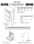
1
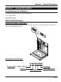
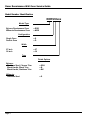
Renaissance Wall Oven
Service Guide
Models: EORS127, EORS130, EORS227, EORS230, EORD227, EORD230, MORS127,
MORS130, MORS227, MORS230, MORD227, MORD230
The Life of the Kitchen.
®
Part No. 106075 Rev. A
®
Specifications subject to change without notice. Dacor assumes no liability for changes to
specifications
© 2008 Dacor, all rights reserved
Dacor Technical Assistance: (800) 353-2267
Table of Contents
Table of Contents
.
Section 1 - Important Safety Instructions .................................. 1
Section 2 - General Information .................................................. 3
Contacting Dacor for Assistance ...................................... 3
Model and Serial Number................................................ 3
Finding the Appliance Data Plate.............................. 3
Reading the Serial Number ...................................... 3
Model Number Identification.................................... 4
Section 3 – Quick Diagnostic Test ............................................... 5
Renaissance Wall Oven Quick ERC/Diagnostic Test ... 5
Test for Upper and Single Ovens............................ 5
Test for Lower Double Ovens................................. 6
Section 4 – Troubleshooting Charts ............................................ 7
Voltage and Continuity ................................................... 7
Membrane Continuity Test ............................................ 13
Section 5 – EOR-MOR Wall Oven Error Codes ........................... 14
Section 6 – Temperature Offset Calibration Instructions ......... 16
Entering Calibration Mode............................................. 16
Calibrating Additional Modes ......................................... 16
Section 7 – Wiring Diagrams ..................................................... 17
v
Dacor Renaissance Wall Oven Service Guide
This page intentionally left blank.
vi
Section 1 - Important Safety Instructions
Section 1 - Important Safety Instructions
WARNING:
f
Operate this appliance only as specified in this manual or the use and care manual.
f
Only a qualified installer should install this appliance.
f
Other than performing procedures specified in the Wall Oven Use and Care Manual, only a qualified service
technician should service this appliance. To obtain the name of your closest Dacor service representative, call
(800) 793-0093. A list of service representatives is also available at www.dacor.com.
f
Before attempting to service or connect this appliance to electrical power, turn off the electrical power supply.
Failure to disconnect the power supply during installation or service may result in electrical shock or fire hazard.
f
This appliance must be properly grounded whenever electrical power is applied.
f
This appliance must be connected to a grounded, metallic, permanent wiring system. The grounding connectors
must be connected to the grounding terminal or lead on the appliance. Failure to do so may result in an
electrical shock hazard.
f
Do not ground this appliance to a gas supply pipe or hot water pipe.
f
A ground connection to a cold water pipe must have a metal continuity to electrical ground and must not be
interrupted by insulating materials. Any insulating materials must be jumped as shown in the installation
instructions.
f
Use only connectors specially designed and certified for joining copper and aluminum to splice the appliance
copper wire to the aluminum house wiring.
f
Do not install a fuse in the neutral or ground circuit during installation. A fuse in the neutral or ground circuit
may result in an electrical shock hazard.
f
Do not install this appliance if the electrical service provided does not meet the product specifications on the
model and serial number plate (see page 3). The electrical service must be installed or changed only by a
licensed electrician.
f
Do not operate this appliance if it has a damaged electrical cord.
f
Failure to install the mounting screws may result in movement or tipping of the oven during use and may result
in personal injury.
f
Use an appliance dolly to move the appliance or when installing it or removing it from the wall for service. Use
of an appliance dolly will minimize the risk of personal injury as a result of the oven tipping.
f
Use the oven only for cooking tasks expected of a home appliance as outlined in this manual. Do not use
corrosive chemicals or vapors in this appliance. This type of oven is specifically designed to heat food. It is not
designed for industrial or laboratory use.
f
Do not touch the interior surfaces of the oven during or immediately after use. Do not allow clothing or other
flammable materials to contact interior surfaces of the oven until they have had sufficient time to cool.
f
Exercise caution when opening the oven door. Let hot air or steam escape before looking or reaching into the
oven.
f
Do not store combustible, flammable, or explosive materials in the oven or in adjacent cabinets.
f
Do not attempt to disengage the oven door’s hinge locks with the door removed from the oven. The hinge
springs could release and cause personal injury.
f
Do not lift or carry the oven door by the door handle.
Page 1
Dacor Renaissance Wall Oven Service Guide
WARNING:
f
Do not line the oven with aluminum foil or other materials. These items can melt or burn up during selfcleaning and cause permanent damage to the oven.
f
Do not use a steam cleaner to clean the oven. Steam could penetrate electrical components and cause a short
circuit.
f
Do not leave metal objects, such as aluminum foil, the meat probe, or cookie sheets, on the floor of the oven.
Objects left on the bottom of the oven could trap heat in the bottom, damaging the bake element. In addition,
the objects themselves could be damaged.
f
Do not air intakes or exhaust slots, anywhere on the oven to become obstructed at any time. Do not operate
the oven if the exhaust deflector below the oven door is bent.
f
The oven automatically locks the oven door during self-cleaning. Do not try to force the door open after it is
locked. Damage to the door and the door latch may result.
f
Before self-cleaning the oven, remove the broiler pan grill and pan, oven racks, convection filter, meat probe,
and any other utensils.
f
Use only the cleaning solutions specified in the use and care manual to clean the inside or outside of the oven.
Other cleaning solutions could produce hazardous fumes, cause corrosion of the metal parts, and could
permanently damage the finishes. Clean only those parts listed in the use and care manual.
f
Take extreme caution when handling the door gasket. Damaging the door gasket in any way may eliminate the
required tight door seal. Clean the gasket only as specified in the use and care manual.
f
Use of meat probes other than the one provided with the oven may result in damage to the meat probe and/or
the oven.
Page 2
Section 2 - General Information
Section 2 - General Information
Contacting Dacor for Assistance
For assistance with installing or servicing Dacor appliances:
Phone: 1-800-353-2267
1440 Bridge Gate Drive
Diamond Bar, CA 91765
Model and Serial Number
Finding the Appliance Data Plate:
It can be seen through the grill located below the control panel. Open the door to expose the grill. On double ovens,
the plate is located behind the top grill.
Reading the Serial Number
X-XX-05310026
Product Code (V = WALL OVEN)
Unit number
Revision
Week of Manufacture
Year of Manufacture
Page 3
Dacor Renaissance Wall Oven Service Guide
Model Number Identification
EORS30xxx
Model Type
Epicure Renaissance Oven
Millennia Renaissance Oven
= EOR
= MOR
Configuration
Single Oven
Double Oven
=S
=D
Width
27 Inch
30 Inch
= 27
= 30
Trim
Finish Options
Epicure:
Stainless Steel, Chrome Trim
Black Handle, Black Trim
Black Handle, Stainless Trim
= SCH
=B
= BK
Millennia:
Stainless Steel
=S
Page 4
Section 3 – Quick Diagnostic Test
Section 3 – Quick Diagnostic Test
Renaissance Wall Oven Quick ERC/Diagnostic Test
Test for Upper and Single Ovens
Test
1
Test Description
Oven lights
2
3
Membrane keypad check
Controller numeric keys
4
Cooling fan function
5
Bake element
6
Broil element
7
Convection element and convection fan
8
Door latch motor engaged
9
Door latch motor disengaged
10
Meat probe operation
11
Lock out
12
12/24 HR clock mode
13
12/24 HR cook mode
14
15
UPO settings
C/F setting
Requirement
Press LIGHT 2 or more times and observe that light turns
On and Off.
Push each individual key and verify audible beep.
Press CLOCK and press each number key. The number
on the key pressed will appear on the display.
Press #, BAKE and then press down key 10 times and
then START. This will put the unit in Sabbath mode with
target temperature of 100 deg F. Verify that cooling fan is
operational.
Press CONV ROAST, 2, 0, 0, START. When the bake
element is on, measure amperage. (Approx. 10-12) amps
are drawn.
Press BROIL, 2, 0, 0, START. When the broil element is
ON, measure amperage. (Approx.13-14) amps are
drawn.
Press PURE CONV, 2, 0, 0, START. When the
convection element is ON, measure. (Approx. 9-10) amps
are drawn. Verify operation of convection fan. If OK,
press CANCEL - SECURE key.
Close oven door and press SELF CLEAN, START.
Check door is locked once lock icon comes on solid on
display and element start cycling.
Press CANCEL - SECURE to cancel SELF CLEAN.
Check door is unlocked once lock icon disappears from
display.
Insert meat probe connector and place meat probe on top
of bake element. Press BAKE, PROBE, START. Verify
PRB icon lit on display and the temperature value
reaches a value of 90 degrees F or more.
Press and hold CANCEL-SECURE key for 5 seconds.
Verify membrane is locked out. Press and hold
CANCEL-SECURE key again for 5 seconds. Verify
membrane operational.
Press CLOCK key for 6 seconds until either "12HR" or
"24HR" shows on the display. Press # button to toggle
between 12HR & 24HR.
Press TIMER 1 key for 6 seconds until the display shows
"ON" or "OFF" . Toggle between "ON" and "OFF" and
then set to "ON". Press # button to toggle between 12HR
and 24HR. Press TIMER 2 key for 6 seconds and until
the display shows "ON" or "OFF”. Toggle between "ON"
and "OFF" and then set to "ON". Press # button to toggle
between 12HR and 24HR.
Press BAKE key for 5 seconds. Set to 00.
Press BROIL key for 5 seconds. Verify that it is set to "F".
If not, press # key to toggle between "C" and "F".
Continued…
Page 5
Dacor Renaissance Wall Oven Service Guide
Test for Lower Double Ovens
Test
16
Test Description
Cooling fan function
17
Bake element
18
Broil element
19
Convection element and convection fan
20
Door latch motor engaged
21
Door latch motor disengaged
22
RTD Test
Page 6
Requirement
Press #, BAKE for lower oven and then press the down
key 10 times, then START. Unit will go into Sabbath
mode with target temperature of 100 deg F. Check that
cooling Fan is ON.
Press CONV ROAST (for lower oven), 2, 0, 0, START.
When the bake element is on, measure amperage.
(Approx. 10-12) amps are drawn.
Press BROIL (for lower oven), 2, 0, 0, START. When the
broil element is ON, measure amperage. (Approx.13-14)
amps are drawn.
Press PURE CONV (for lower oven), 2, 0, 0, START.
When the convection element is ON, measure. (Approx.
9-10) amps are drawn. Verify operation of convection fan.
If OK, press CANCEL - SECURE key.
Close lower oven door and press SELF CLEAN key for
lower oven, then START. Check door is locked once lock
icon comes on solid on display and element start cycling.
Press CANCEL - SECURE to cancel SELF CLEAN.
Check lower door is unlocked once lock icon disappears
from display.
Insert meat probe connector and place meat probe on top
of bake element. Press BAKE (for lower oven), PROBE,
then START. Verify PRB icon lit on display and the
temperature value reaches a value of 90 degrees F or
more.
Section 4 – Troubleshooting Charts
Section 4 – Troubleshooting Charts
Voltage and Continuity
Symptoms
All the voltage test points will be at the relay board.
No clock display
While power is on check the following Voltages:
1) P3 pin 4 - P3 pin 5 = 5 VDC (check both relay and display board).
2) P3 pin 6 - P3 pin 7 = 12 VDC (check both relay and display board)
If one the above voltages not present check connection to P3 connector.
If cable is properly connected, then replace it.
3) NEUTRAL (terminal block) - L1 (terminal block) = 120 VAC.
4) NEUT (P6) - L1C (P4) = 120 VAC.
5) White external wire to black external wire = 120 VAC.
If one the above voltages is not present, turn OFF oven and do continuity
check:
6) L1 (terminal block) to L1C.
7) NEUTRAL (terminal block) to NEUT (P4).
8) Black external oven wire to L1(terminal block)
9) White external oven wire to N (terminal block)
Establish proper connection if disconnected or miss-wired. Also check the
household circuit breaker to see if it is in the OFF position or has been
tripped.
10) If all of the above connections are good, but problem persists, replace the
relay board.
11) If by replacing relay board problem is not fixed, replace the display board
as last resort.
No elements cycling in
ALL modes
1) Make sure that the display lights up. If not, see No Clock Display above.
2) Turn OFF power, check continuity of Hi-Limit Switch. If no continuity,
press Hi-Limit reset button. Turn ON power and rerun different modes to
test if all elements turn ON properly.
3) If step 2 does not solve the problem, while oven power is OFF, check to
see if oven’s red, black, white and green wires are connected to the
corresponding red, black whites and green wires of the source. Make
sure they are not miss-wired or disconnected. Also check corresponding
red, black and white power source cable wire has continuity to
corresponding red, white and black terminals on the terminal block. The
green wire of the oven is connected to chassis. Check continuity of the
following wires on the faulty cell:
4) Check upper or single elements, L1 to L1A.
5) Check lower elements, L1 to L1B.
6) Check upper or single elements, L2 to K7 L2 IN1.
7) Check lower elements, L2 to K4 L2 IN2.
If no continuity, tighten terminal block, change wire or wire terminals.
Turn ON Power. Check the following…
8) L1 - L2 = 240 VAC.
9) L1A - L2 = 240 VAC (Upper/Single elements). Conitniued…
Page 7
Dacor Renaissance Wall Oven Service Guide
Symptoms
No elements cycling in
ALL modes (cont.)
Bake element only is not
cycling during preheat,
bake, conv bake, conv
roast, self clean, HOLD
Page 8
All the voltage test points will be at the relay board.
10) L1B - L2 = 240 VAC (Lower elements). Continued…
If continuity tests on previous page and above are good and voltage
check is good, run any mode on faulty cells and check the following…
11) K7 L2 IN1 – K7 L2 OUT1 = 0 VAC (upper/single DLB relay)
12) K4 L2 IN2 – K4 L2 OUT2 = 0 VAC (lower DLB relay)
If more than 100 VAC is present then the DLB relay it is not activating
due to faulty communication with the display board. Check the
following…
13) Make sure P3 connector and cable are properly connected. If in doubt
replace with new P3 cable.
14) See if the DLB relay is damaged. If so replace relay board.
15) If the above does not work, replace the display board as last resort.
16) Upon replacement of wires, connectors, relay board or display board,
rerun the above test to confirm problem is corrected.
1) Make sure that only the bake element is not cycling. If the other elements
are not cycling, see No elements cycling in ALL modes on previous
page.
2) Start with a cold oven and run BAKE, CONV BAKE, etc. on the faulty cell
and make sure that oven goes to preheat mode. If it does not go to
preheat, cool down the oven and rerun the mode until it is cold enough to
go into preheat. Once oven goes into preheat, test these point of the
faulty cell using voltmeter. The voltages should follow the preheat cycling
pattern:
3) Check upper or single bake, K7 L2 OUT1 – BAKE 1 (P19) (Check upper
BAKE ON and OFF time)
4) Check lower bake, K4 L2 OUT2 – BAKE 2 (P24) (Check lower BAKE ON
and OFF time).
5) If the oven is in preheat and there is no activity and no cycling indicated
by voltmeter, then the bake relay is damaged and relay board needs to
be replaced. Upon replacement do the same test again.
6) If there is activity indicated by voltmeter, then turn OFF the power and
check the bake element resistance on the following terminals:
7) Check upper or single bake element, K7 L2 OUT1 - BAKE 1 (P19) =
approximately 20 ohms.
8) Check lower bake element, K4 L2 OUT2 - BAKE 2 (P24) =
approximately 20 ohms.
9) If resistance is high, then check for continuity of the bake element wires
on the faulty cell:
10) Check upper or single bake wire, BAKE 1(P19) to Upper Bake Element
terminal.
11) Check lower bake wire, BAKE 2(P24) to lower bake element terminal.
12) Check upper or single bake wire, K7 L2 OUT1 to the other upper bake
element terminal.
13) Check lower bake wire, K4 L2 OUT2 to the other lower bake element
terminal.
14) If continuity is good for all wires, check to make sure the bake element
connector is connected to the bake element terminal. If connection good,
disconnect bake connections and directly measure the bake element
resistance and if it not near 20 ohms, replace bake element. Continued…
Section 4 – Troubleshooting Charts
Symptoms
Bake element only is not
cycling during preheat,
bake, conv bake, conv
roast, self clean, HOLD
(cont.)
Broil element only is not
cycling during Preheat,
Bake, Conv Bake, Conv
Roast, Broil, Conv Broil,
and Self Clean
Convection element only
is not cycling during
preheat and Pure
Convection
All the voltage test points will be at the relay board.
15) Upon replacement of wires, connectors, relay board or display board,
rerun the above test to confirm problem is corrected.
1) Make sure that only the broil element is not cycling. If the other elements
are not cycling, see No elements cycling in ALL modes section.
2) Start with a cold oven and run BROIL or CONV BROIL on the faulty oven
cell. Check these test points using voltmeter on the faulty cell. The
voltages should follow the appropriate broil cycling pattern:
3) Check upper/single broil, K7 L2 OUT1 – BROIL 1 (P15) = 240 VAC.
4) Check lower broil, K4 L2 OUT2 – BROIL 2 (P18) = 240 VAC.
5) If above terminals do not read 240 VAC when suggested mode is
running and the oven started cold, then the broil relay is not cycling or is
damaged. Replace relay board. Upon replacement repeat the same test
again.
6) If there is activity then turn OFF the power and check the broil element
resistance on the following terminals:
7) Check upper/single broil, K7 L2 OUT1 - BROIL 1 (P19) = approximately
18 ohms.
8) Check lower broil, K4 L2 OUT2 - BROIL 2 (P24) = approximately 18
ohms.
9) If resistance is high, check for continuity of the wires of the faulty cell:
10) Check upper/single broil wire, BROIL 1 (P15) to upper broil element
terminal (upper/single).
11) Check lower broil wire, BROIL 2 (P18) to lower broil element terminal
12) To check upper/single broil, K7 L2 OUT1 to the other upper broil element
terminal (upper/single).
13) To check lower broil, K4 L2 OUT2 to the other lower broil element
terminal.
14) If continuity is good then make sure the broil element connector is
connected to the broil element terminal. If connection is good, then
disconnect the broil connections and directly measure the broil element
resistance and if it not near 18 ohms replace broil element.
15) Upon replacement of wires, connectors, relay board or display board,
rerun the above test to confirm problem is corrected.
1) Make sure that only the convection element is not cycling. If the other
elements are not cycling, see No elements cycling in ALL modes
section.
2) Start with a cold oven and run PURE CONVECTION with target of 200
degrees F on the faulty oven cell. Make sure that it does not go to
Preheat and check these test points using voltmeter and should follow
the Cycling Pattern:
3) Check upper/single convection, K7 L2 OUT1 – CONV 1 (P14) = 240
VAC.
4) Check lower convection, K4 L2 OUT2 – CONV 2 (P5) = 240 VAC.
Continued….
Page 9
Dacor Renaissance Wall Oven Service Guide
Symptoms
Convection element only
is not cycling during
preheat and Pure
Convection (cont.)
Convection Fan does not
run during Preheat, Conv
Bake, Conv Broil, Conv
Roast.
Page 10
All the voltage test points will be at the relay board.
5) If above mentioned terminals do not read 240 VAC when suggested
mode is running and the oven started cold then the convectionl relay is
not cycling or is damaged. Replace the relay board. Upon replacement
do the same test again.
6) If there is activity then turn OFF the power and check the broil element
resistance on the following terminals:
7) Check upper/single convection, K7 L2 OUT1 - CONV 1(P19) =
approximately 25 ohms.
8) Check lower convection, K4 L2 OUT2 - CONV 2(P24) = approximately
25 ohms.
9) If resistance is high, check for continuity of the wires as follows:
10) Check upper/single convection wire, CONV 1 (P14) to upper broil
element terminal
11) Check lower convection wire, CONV 2 (P5) to lower broil element
terminal
12) Check upper/single convection wire, K7 L2 OUT1 to the other upper
convection element terminal
13) Check lower convection wire, K4 L2 OUT2 to the other lower convection
element terminal
14) If continuity is good then make sure convection element connector is
connected to the convection element terminal. If connection is good, then
disconnect the convection connections and directly measure the
convection element resistance. If it is not near 25 ohms replace
convection element.
1) Start with a cold oven and run any modes that will turn on the Convection
fan e.g. Preheat, Pure Convection, Convection Bake, etc. If the fan does
not run check across the following test points on faulty cell:
2) Check upper/single convection fan, Neutral to P11 pin 3 = 120 VAC
upper/single convection fan.
3) Check lower convection fan, Neutral to P11 pin 7 = 120VAC (lower
convection fan).
4) If no voltage measured or convection fan not running, turn OFF power
and check continuity on following wires:
5) Neutral to NEUT (P6). If no continuity, change wire or wire terminal or
tighten neutral connection on the terminal block.
6) If there is continuity, check resistance on these test points:
7) Check upper/single convection fan, neutral - P11 pin 3 = approximately
13 ohm.
8) Check lower convection fan, neutral - P11 pin 7 = approximately 13
ohms.
9) If resistance is high, check continuity on the following wires:
10) Check upper/single convection fan, P11 pin 3 to one terminal of the upper
convection fan.
11) Check lower convection fan, P11 pin 7 to one terminal of the lower
convection fan. Also check if the other end of the convection fan is
connected to neutral. If connected change the wire or connector or the
terminal if no continuity present. Continued…
Section 4 – Troubleshooting Charts
Symptoms
Convection Fan does
not run during Preheat,
Conv Bake, Conv Broil,
Conv Roast (cont.)
Cooling fan does not turn
on at designated turn ON
temperature
Latch motor not running
during Self Clean
All the voltage test points will be at the relay board.
12) If connection is good, disconnect convection fan and measure the
resistance directly. Resistance should be approximately 13 ohms across
the terminals.
13) If convection fan resistance is good, and connections are good then the
convection fan relay is bad. Replace the relay board. Upon replacement
do the same test again.
14) If problem still persists, replace the display board as last resort.
1) Start with a cold oven and run Sabbath mode to turn ON the cooling fan
immediately. If it does not run, measure voltage on the following test
points:
2) Check upper/single cooling fan, Neutral to P11 pin 2 = 120 VAC
upper/single cooling fan.
3) Check lower cooling Fan, neutral to P11 pin 8 = 120VAC (lower cooling
fan).
4) If no voltage for either of the above or cooling fan not running, turn OFF
power and check continuity on following wires:
5) Neutral to NEUT (P6). If no continuity, change wire or wire terminal or
tighten neutral connection on the terminal block.
6) If there is continuity, check resistance on following test points:
7) To check upper/single cooling fan, Neutral - P11 Pin 2 = approximately
18 ohms.
8) To check lower cooling fan, neutral - P11 Pin 8 = approximately 18
ohms.
9) If resistance is high, check continuity on the following wires:
10) Check upper/single cooling fan, P11 Pin 2 to one terminal of the upper
cooling fan.
11) Check lower cooling fan, P11 Pin 8 to one terminal of the lower cooling
fan.
12) Make sure other end of the cooling fan wiring is connected to Neutral. If
properly connected, change the wire or connector or the terminal if no
continuity.
13) If connection is good, disconnect the cooling fan and directly measure the
resistance across the terminals. It should be approximately 18 ohms
across the terminals.
14) If cooling fan resistance is OK and connections are good, then the
cooling fan relay is bad. Replace the relay board. Upon replacement do
the same test again.
15) If problem still persists, replace the display board as last resort.
1) Start Self Clean mode and immediately check to see if the latch motor
runs. If it does not run, measure voltage on the following test points:
2) Check upper/single latch motor: Neutral to P11 Pin 1 = 120 VAC
upper/single cooling fan.
4) Check lower latch motor: Neutral to P11 Pin 9 = 120VAC (lower cooling
fan)
5) If no voltage or latch motor not running, turn OFF power and check
continuity on following wires:
6) Neutral to NEUT (P6). If no continuity, change wire or wire terminal or
tighten neutral connection on the terminal block. Continued…
Page 11
Dacor Renaissance Wall Oven Service Guide
Symptoms
Latch motor not running
during Self Clean (cont.)
No oven light only
No heat in any cooking
mode
Oven sensor failure
Failure Code U30/31
Latch switch circuit
Page 12
All the voltage test points will be at the relay board.
7) If there is continuity, check resistance on these test points:
8) Check upper/single latch motor, Neutral - P11 Pin 1 = approximately 18
ohms.
9) Check lower latch motor, Neutral - P11 Pin 9 = approximately 18 ohms.
10) If resistance is high, check continuity on the following wires:
11) Check upper/single latch motor, P11 Pin 1 to one terminal of the upper
cooling fan.
12) Check lower latch motor, P11 Pin 9 to one terminal of the lower cooling
fan. Also check if the other end of the latch motor harness is connected to
Neutral. If so, change the wire or connector or the terminal if no
continuity.
13) If connection is good, disconnect the latch motor and directly measure the
resistance across the terminals. It should be approximately 18 ohms.
14) If Latch Motor resistance is OK and connections are good, then the
cooling fan relay is bad. Replace the relay board. Upon replacement do
the same test again.
15) If problem still persists, replace the display board as last resort.
1) Turn light ON and check voltage on the following test points:
2) Connector P11 wire # 4 to Neutral power output to light transformer =
120VAC. If no voltage replace relay board.
3) If voltage is present, check output voltage of light transformer. If no
voltage, replace light transformer.
4) If transformer voltage OK, Check wire 8 & 10 right oven light (12V) and 6
& 8 wire left oven light (12V).
1) Check across test points:
2) Check house supply into relay board at L1C to L2 IN = 240 VAC
3) Check for open HTC hi-temp cutout located off to the right of the self
clean latch.
1) Check across test points:
2) Pull connector P5 off of the back side of the ERC Control/Clock Check
across wire 1 & 3 (White Wire) Should read between 1050 to 1100
OHM`S. Check each wire to ground for pinch or shorted wire. Check two
white for good connection into the P5 connector.
1) Check across test points.
2) Pull connector P5 off the back side of the ERC Control it is a 12 pin
connector. In connection 9 Black /11Blue/Yellow 12. P9 is the Com. on
both latch switches. With the latch in the OPEN position there should be
continuity between connection 9 Black and 12 yellow.
3) Latch in the lock position continuity is between connection Black 9 and
Blue #11.
Section 4 – Troubleshooting Charts
Membrane Continuity Test
To test for non-functioning membrane touchpad, disconnect the membrane/touchpad ribbon connector from the ERC
controller. The ribbon connector is numbered from 1 to 14 counting from the top down. Use an Ohm meter to test
across the following test points. A reading above 5 Ohms across any of the test points listed below indicates the
membrane is bad and needs to be replaced.
SINGLE/UPPER OVEN TEST POINTS
Button/Pad
Check across test points
Button/Pad
Check across test points
1
CONVECTION ROAST 12 & 5
15 CANCEL
8&5
2
CONVECTION BAKE
12 & 1
16 OVEN LIGHT
3&5
3
BAKE
10 & 1
17 START
7&5
4
START TIME
8&1
18 POUND SIGN
2&5
5
CONVECTION BROIL
12 & 9
19 NUMBER 1
3&1
6
BROIL
10 & 9
20 NUMBER 2
1&2
7
DURATION
8&9
21 NUMBER 3
4&1
8
CLOCK
7&9
22 NUMBER 4
3&9
9
PURE CONVECTION
12 & 11
23 NUMBER 5
2&9
10 PROBE
10 & 11
24 NUMBER 6
4&9
11 STOP TIME
8 & 11
25 NUMBER 7
3 & 11
12 TIMER 1
7&1
26 NUMBER 8
2 & 11
13 TIMER 2
11 & 7
27 NUMBER 9
4 & 11
14 SELF CLEAN
10 & 5
28 NUMBER 0
4&5
LOWER OVEN TEST POINTS
Button/Pad
Check across test points
1
CONVECTION ROAST 7 & 6
2
CONVECTION BAKE
12 & 6
3
BAKE
12 & 14
4
START TIME
3 & 14
5
CONVECTION BROIL
10 & 6
6
BROIL
10 & 14
7
DURATION
2&6
8
CANCEL
3&6
9
PURE CONVECTION
8&6
10 PROBE
8 & 14
11 STOP TIME
2 & 14
12 SELF CLEAN
7 & 14
Figure 4-1 Control Panel
Page 13
Dacor Renaissance Wall Oven Service Guide
Section 5 – EOR-MOR Wall Oven Error Codes
Displayed
Error
Message
Error
Condition
Max/Min
Bounds
Max/Min
Bounds
Stored in
EEPROM?
Software Logic Description
No
Shorted Key Failure
Control Errors
C01
Shorted Key
Failure
A release
of the key
is not seen
for two
minutes
C23
OCC Ambient
Over
Temperature
80°C
No
Control Board Ambient temperature is above 80°C.
Oven shuts down with the cooling fans turns ON until the
ambient temperature falls to 50°C.
N/A
No
Control Board Open thermistor detected.
N/A
No
Control Board Shorted thermistor detected.
80°C
No
Relay Board Ambient temperature is above 80°C. Oven
shuts down with the cooling fans turns ON until the
ambient temperature falls to 50°C.
N/A
No
Relay Board Open thermistor detected.
N/A
No
Relay Board Shorted thermistor detected.
C24
C25
C33
C34
C35
Ambient
Temperature
probe open
Ambient
Temperature
probe shorted
OCC Ambient
Over
Temperature
Ambient
Temperature
probe open
Ambient
Temperature
probe shorted
-
C41
A/D
Reference
Readings
N/A
No
Safety check to insure the RTD oven temperatures are
correct
C42
E2 Checksum
Failure on
Control board
N/A
Yes
Calculated E2 checksum does not agree with the stored
E2 checksum.
C44
FLASH
Checksum
Failure on
Control board
N/A
No
Calculated FLASH checksum does not agree with the
stored FLASH checksum.
C76
Incorrect
oven type:
Single/Double
N/A
No
Displays error after 3 seconds of sensing an incorrect
configuration. This error is reversible.
Page 14
Section 5 – EOR-MOR Wall Oven Error Codes
Displayed
Error
Message
Error
Condition
Max/Min
Bounds
Max/Min
Bounds
Stored in
EEPROM?
Software Logic Description
Oven Errors U = UPPER OVEN / L = LOWER OVEN
U20 / L20
Cook over
temperature -
610°F
Yes
Center of oven cavity temperatures above the maximum
bounds.
U21 / L21
Clean over
temperature -
890°
Yes
Center of oven cavity temperatures above the maximum
bounds.
U30 / L30
Open RTD -
N/A
No
N/A
No
N/A
N/A
N/A
N/A
N/A
No
U31 / L31
U50 / L50
U51 / L51
U80
Shorted RTD
Latch Lock
Failure
Latch Phase
Failure
Shorted meat
probe – upper
Fatal Error. Continuous A/D values over maximum
bounds.
Fatal Error Continuous A/D values over minimum
bounds.
Fatal Error. The door lock is not detected while locking
the door.
Fatal Error. The door phase switch (LATCH NC) is not
detected while locking the door.
The meat probe for the upper oven is shorted
Page 15
Dacor Renaissance Wall Oven Service Guide
Section 6 – Temperature Offset Calibration Instructions
Entering Calibration Mode
1)
2)
3)
4)
Press and hold the “0” and “#” keys. The display will show the word “PASS”.
Using the number keypad enter 6428 then press the Start key.
The display will change and read “SLCE” “00”. Quickly move to step 4.
Select the cooking mode that needs to be calibrated for example “BAKE“. Using the number keypad enter the
new calibration offset for example “25”. Using the number keypad press “#” to toggle between + and –. Press
the START key. This will lock the calibration. Press the CANCEL - SECURE key to complete procedure.
Calibrating Additional Modes
5) Without pressing CANCEL - SECURE to complete: repeat step 4 and select new mode for example “PURE
CONV”.
6) Using the number keypad enter the new calibration offset for example “20”.
7) Using the number keypad press “#” to toggle between + and -.
8) Press the START key. This will lock the calibration.
9) Press the CANCEL - SECURE key to complete procedure.
Page 16
Section 7 – Wiring Diagrams
Section 7 – Wiring Diagrams
Page 17
Dacor Renaissance Wall Oven Service Guide
Page 18
Section 7 – Wiring Diagrams
Page 19
®
The Life of the Kitchen.