1
Quick Start Installation Guide
Table of Contents
1.
Introduction ................................................................................................ 3
2.
System Installation .................................................................................... 3
3.
System Programming ................................................................................ 5
3.1.
Keys Menu Navigation ................................................................ 5
3.2.
Enter Engineer Programming mode ....................................... 5
3.3.
Selecting a language and Defaults ........................................ 5
3.4.
Registering Wireless Devices .................................................. 5
3.4.1.
3.4.2.
3.4.3.
Detectors .................................................................................................... 6
Keyfobs ...................................................................................................... 8
Wireless keypads ....................................................................................... 9
3.5.
Program Communication to Monitoring Station ................ 9
3.6.
Set Up Follow Me Destination................................................ 10
3.7.
Set Time & Date ......................................................................... 11
3.8.
Set/Edit Users .............................................................................. 11
3.9.
Set GPRS Communication ....................................................... 13
Connect to MyELAS ............................................................................... 13
4.
Testing the System .................................................................................. 15
2
1. Introduction
Thank you for choosing CommPact wireless intruder Control Panel. This quick start
guide manual describes the main steps for installing and programming the CommPact
Control Panel using the keypad on the main unit. To download the full version of the
CommPact Installation Manual go to www.riscogroup.co.uk, enter the Downloads menu
and select Electronics Line Manuals.
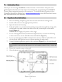
2. System Installation
1.
Place the drilling template against the wall and mark the mounting holes.
2.
Install wall anchors in the appropriate positions.
3.
Open the main unit housing.
4.
If the AC cable is not connected thread the power cable through the wiring hole
on the back cover and connect the cable to the AC power input on the main
board (Figure 1).
Caution: Do not apply AC power at this stage.
5.
In case of using Wired Zone, PGM and Telephone/Line, connect the following
to their connectors on the Main Board terminal block (Figure 2)
6.
If your system supports GPRS communication, insert a SIM card (the SIM card
can be placed from the back cover without opening the main unit).
7.
Connect the backup Battery pack to the connector (Figure 3) on the main board.
Note:
If the sounder is activated enter the master user code number (default '1234') to silence the
alarm.
8.
Mount the control system to the wall
9.
Close the front cover and apply AC power.
Figure 1: Back cover
3
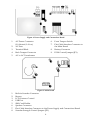
Figure 2: Power Supply and Connections Board
1.
AC Power Connector
(N=Neutral, L=Live)
6.
Front Tamper Switch
2.
AC Fuse
7.
Flat-Cable Interface Connector to
the Main Board
3.
Terminal Block
8.
Battery Connector
4.
Back Tamper Connector
9.
PGM Control Jumper (JP1)
5.
AC to AC Transformer
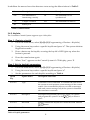
Figure 3: Main board
1.
2.
3.
4.
5.
6.
7.
8.
Built-in Sounder Connector
Buzzer
LCD Contrast Control
USB Port
SIM-Card Holder
Speaker Connector
Flat-Cable Interface Connector to the Power Supply and Connections Board
Sounder Strength Control Jumper (JP1)
4
3. System Programming
3.1. Keys Menu Navigation
Program the CommPact from the keypad located on the main unit (see Table 1).
Enter / Save (to move to the displayed menu or to save the updated data)
Cancel the current selection or return to previous menu
Scroll up or down through the menu options
/
[1]-[0]
1. Enter numeric values where required.
2. For quick key programming.
Press the number keys to access a programming option.
3. Edit descriptors.
Table 1: Keypad usage
3.2. Enter Engineer Programming mode
1.
Go to the default menu and press '√'.
2.
Enter your engineer code (default code '1111').
3.
Using the arrow keys, select '[9] Programming'
3.3. Selecting a language and Defaults
The CommPact supports several languages. For easy operation, change the system
language as follows:
1.
2.
Go to the main menu select [9]>[7]>[1] (Programming > Initialize > Init All)
Select default and press '√'. Select language (Voice + LCD display) and press '√'.
Note:
Setting language and defaults automatically initializes the Control System. All existing
configuration settings are reset to the default settings and all previously registered
transmitter settings are erased.
3.4. Registering Wireless Devices
Every device has to be registered to the Control Panel in order to be recognized.
It is recommended to register all devices to the control panel before installing. To install
the wireless devices/accessories temporarily fit them in the desired locations and then
perform a range test. Testing may show you should relocate the panel or some of its
devices/accessories.
Note:
For wireless sounder registration refer to the full installation manual.
5
3.4.1. Detectors
The CommPact supports 33 security zones. Only one detector can be registered to each
zone. Zones 1-32 are intended for wireless detectors by default. Zone 33 is an on-board
hardwire zone (can be configured as NO, NC or EOL).
Step 1: Register a detector
1.
Go to the main menu and select [9]>[1]>[1] (Programming> Devices > Zones)
2.
Using the arrow keys, select a specific zone and press '√'. The system initiates
Registration mode.
3.
Send two transmissions from the detector. A confirmation sound is heard after
each successful signal (chime sound). After two successful transmissions a
confirmation beep is heard.
Sending the transmissions can be done in several ways, as summarized in
Table 2.
Device
PIR Detectors
Device Model
Number
Sending Transmissions
EL-2645
Apply battery power. Place the mode
jumper over pins 2 and 3 (Radio Mode);
the LED flashes.
EL-2645PI
OR
Depress the tamper switch twice, in rapid
succession.
Magnetic Contact
EL-2601
Flood Sensor
EL-2661
Universal
Transmitter
EL-2602
Glass break
EL-2606
Smoke Detector
When you apply battery power and the
tamper switch is open, the device enters
test mode in which a transmission is sent
every few seconds. You can terminate the
test mode by closing the tamper switch.
Press the test button. Verify that the
transmission LED is lit momentarily. Wait
five seconds and press the test button
again.
EL-2603
Table 2: Transmission sending
4.
After the detector is successfully registered the display shows: 'Save?'
Press '√' to confirm and continue entering other parameters for the chosen
device (see section below) or press X to go back and enroll additional zones.
Step 2: Set detector's parameters
1.
Go to the main menu and select [9]>[1]>[1] (Programming > Devices > Zones)
2.
Using the arrow keys select a specific zone and press '√'.
3.
Set the main parameters for each zone, according to Table 3
6
Quick
Key
Option Name
Description and Notes
9>1>1>2
Zone Type
The alarm this zone generates
9>1>1>3
Set
Setting methods in which the zone is included.
1 (F): The zone is included in Full setting
2 (P): The zone is included in Part setting
3 (PE): The zone is included in Perimeter setting
9>1>1>4
Descriptor
Descriptors help identify the device when you operate
and program the system.
9>1>1>5
Bell (Sounder)
Activate the sounder when the zone is triggered
9>1>1>6
Chime
Activate the internal sounder when the zone is triggered.
Note: To allow the chime option enable Global Chime
option [Quick key 7>12]
9>1>1>7
Force Set
Enables to set the system even if this zone is not ready.
For the force set feature to function, you must also enable
force setting in system options.
Table 3: Parameter set
4.
If required scroll thorough the other menu parameters and modify settings.
Step 3: Test the detectors
1.
Go to the main menu and press '√'.
2.
Enter your engineer code (default code '1111').
3.
Enter [7]>[07]>[2] (Service > Transmitters > TX Test) to initiate the TX
communication test. This test enables to identify transmitters and test their
signal strength.
4.
Activate the transmitter to test; the transmitter’s details appear on the
CommPact LCD and a sequence of tones is heard indicating the transmitter’s
signal strength.
Signal Strength
Tones
0-2
1 Tone
3-5
2 Tones
6-8
3 Tones
8-9
4 Tones
Table 4: Signal strength
7
Note:
If the signal strength is less
than 6, place the devices in
a better location.
In addition the menu shows the detectors status using the abbreviations in Table 5.
Item
Description…
Item
Description…
OK
The transmitter is
functioning correctly
OS
The transmitter is not
synchronized
TA
Tamper condition
NA
The transmitter is inactive
BT
Battery low
Table 5: Abbreviations
3.4.2. Keyfobs
The CommPact Control System supports up to 19 keyfobs.
Step 1: Register a keyfob
1.
Go to the main menu, select [9]>[1]>[2] (Programming > Devices > Keyfobs)
2.
Using the arrow keys select a specific keyfob and press '√'. The system initiates
Registration mode.
3.
Press a button on the keyfob, assuring the keyfob’s LED lights up when the
button is pressed.
4.
Press the same button again.
5.
When 'Save?' appears on the Control System’s LCD display, press '√'.
Step 2: Set the keyfob's parameters
1.
Go to the main menu, select [9]>[1]>[2] (Programming > Devices > Keyfobs)
2.
Using the arrow keys select a specific keyfob and press '√'.
3.
Set the parameters for each keyfob according to Table 6.
Quick
Key
Option Name
Description and Notes
9>1>2>2
Type
Controlled or non-controlled. A controlled keyfob causes
the system to send set/unset event messages to the central
station. Non-controlled keyfobs never send set messages
and send a unset message only if the system is disarmed
after an alarm occurrence
9>1>2>3
Descriptor
Descriptors help identify the device when you operate
key to insert a
and program the system. Use the /
space
9>1>2>4
KF1 PGM
Defines whether the keyfob can control the PGM with the
/
button.
9>1>2>5
Delete
Delete a keyfob
Table 6: Keyfob parameters
8
Step 3: Testing the keyfobs
1.
Go to the main menu and press '√'.
2.
Enter your Engineer code (default code '1111').
3.
Enter [7]>[07]>[2] (Service > Transmitters > TX Test) to initiate TX
communication Test. Review the explanation in Detectors section.
3.4.3. Wireless keypads
Step 1: Register a wireless keypad
The CommPact supports up to four wireless keypads.
1.
Go to the main menu, select [9]>[1]>[3] (Programming > Devices > Keypads) .
2.
Select the keypad to register and press '√'. The system initiates Registration
mode.
3.
Press a button on the keypad assuring a LED lights up when the button is
pressed.
4.
Press the same button again. When 'Save?' appears on the Control System’s
LCD display, press '√'.
5.
Set the keypad descriptor.
Note:
The above procedure refers to keypad EL2620 and EL 2640. For registration keypads
EL2621 refer to the full installation manual.
Step 2: Test a keypad
1.
Go to the main menu and press '√'.
2.
Enter your Engineer code (default code '1111').
3.
Enter [7]>[07]>[2] (Service > Transmitters > TX Test) to initiate the TX
communication test. Review the explanation in Detectors section.
3.5. Program Communication to Monitoring Station
This section describes the main parameters to establish communication between the
CommPact and the CMS (Control Monitoring Station).
1.
Enter the engineer programming menu.
2.
Select [5]>[1] (Communication > Accounts).
3.
Select the account to be used for CMS report and press '√'.
4.
Define the parameters as seen in Table 7.
9
Quick
Key
Option Name
Description and Notes
9>5>1>1
Telephone No.
Enter phone number. Use the
"T",",","P","+","*","#".
9>5>1>2
Protocol
Used to define the account’s communication protocol.
For CMS accounts select one of the options: IP
protocol, SMS Contact ID, SMS SIA, SIA, Contact ID
key to enter
Note: Set account 1 to IP protocol if you use GPRS
9>5>1>3
Communication
Interface
Program an account’s communication interface. Select
PSTN, GSM, or GPRS (GPRS can be used only for the
account 1)
9>5>1>4
Two-Way Audio
Enable/Disable two-way audio communication
between the Control Panel and the operator at the
CMS.
9>5>1>5
Account number
Enter up to eight digits. Enter leading zeros for
account numbers of less than eight digits. Use the
key to enter hexadecimal digits.
If the programmed protocol is Contact ID, "A" is not a
valid entry in the account number.
9>5>1>6
Call Attempts
The Call Attempts option determines the number of
times the system tries to call a telephone number
before moving on to the next number in sequence
This feature is not available for voice report.
9>5>1>7
Account Type
Select whether the account is Primary or Backup. The
first account is always primary, while every other
account (that is not a voice report) may be chosen as
primary or backup. Each primary account may have
one, several, or no backup accounts at all
Table 7: Quick keys
3.6. Set Up Follow Me Destination
Follow-Me feature is designed to notify a user an alarm event has occurred. To set up
follow me define relevant accounts as follows;
1.
Enter the engineer programming menu.
2.
Select [5]>[1] (Communication > Accounts)
3.
Select an account to be used for Follow Me and press '√'.
10
Note:
Account number 3 is designed for using Follow me feature. It is the only telephone
number that can be programmed by the user in the following location (only if defined as
SMS or TWA): Main menu > '[5] Follow Me Number'
4.
Enter the Follow Me telephone number and press '√'
5.
Select the protocol from the following options:
6.
7.
Two Way Audio Follow Me
SMS Follow Me
Voice Report
Define the communication interface for Follow me: PSTN or GSM.
Scroll thorough the other menu parameters and press '√' to confirm.
Note:
Using the ELAS, the number of Follow me destinations by SMS or Email can be expanded.
3.7. Set Time & Date
The time and date are used to stamp events in the event log. Additionally the time is
displayed on the LCD.
1.
Go to the main menu and press '√'.
2.
Enter engineer code (default code '1111')
3.
Select [7] > [01] (Service > Set Time/Date).
4.
Select '[1] Set Time'. Enter the current time and press '√'
5.
The display shows '[2] Set Date' option. Enter the current date and press '√'.
Note:
If the time is set in 12hr format, use the
key to toggle between AM and PM.
3.8. Set/Edit Users
The CommPact supports up to 32 individual user codes. Each of these codes is four
digits long. The ability to perform an operation is defined by your user code’s
authorization level. Each code is defined with its own authority level. Follow Table 8 to
view the authorization level assigned to each of the codes.
Notes:
Codes 1-29 can be edited only by the Master code.
Codes 30, 32 can only be edited by the engineer. (Code 32 - Engineer code, Code 30 the
Central Station TWA Code)
11
Code
Number
Authorization
Level
Description
1
Master Code
With the master code, you can edit all other user codes
except the Engineer code and the Central Station TWA
Code.
Caution: The default master code is 1234. Change this
code immediately after installing the system!
2-19
Controlled
Codes
When you use a controlled user code for setting and
unsetting, the control system notifies the central station
with a Set/Unset event message
20-25
Non-controlled
Codes
Non-controlled codes do not cause the system to send
Set/Unset event messages to the central station.
26-27
Limited Codes
Valid only for 24 hours. These codes are "controlled"
28
Duress Code
Designed for situations where the user is being forced
to operate the system.
29
Telecontrol
Code
Designed to enable the user to perform a number of
tasks via their telephone when establishing remote
connection to the system via the phone.
30
Central Station
TWA Code
Designed to enable the central station's operator to
establish two-way audio communication with the
Control System within ten minutes after an alarm or to
stop the bell.
32
Engineer Code
The engineer code grants access to the programming
menu and the service menu.
Caution: The default Engineer code is 1111. Change
this code immediately after installing the system!
Table 8: Authorization level
To Set/Edit user code
1.
Go to the main menu and press '√'.
2.
Enter master code (default code '1234')
3.
Select '[4] User Codes'
4.
Select the code to edit and press '√'.
5.
The display shows '[1] Edit Code' and Press '√'.
6.
Type the new code and press '√' to confirm
7.
Scroll down to '[2] Descriptor' and press '√'
8.
Type user name and press '√' to confirm
12
9.
Press X and select another user.
10. Repeat stages 4–9 to set the code for additional users.
Notes:
To delete the code, enter: '0000'
The engineer and master codes cannot be deleted.
3.9. Set GPRS Communication
To establish GPRS communication:
1.
Make sure the SIM card ID is installed inside the communication module.
Note:
If you need to install a new SIM card on the communication module and you use PIN
code, it should be programmed in the control system before inserting the SIM card in the
Main Board.
2.
Edit the APN (Access Point Name) of your GPRS connection:
a.
Go to the main menu and press '√'.
b.
Enter engineer code (default code '1111')
c.
Select [9] > [5] > [7] > [6] > [1] (Programming > Communications >
Internet > GPRS Options > APN)
d.
Enter the APN name provided by the cellular provider.
e.
Press '√' once editing operation is done.
Note:
To enable GPRS communication Account 1 protocol must be defined as IP and the account
interface should be defined as GPRS.
Connect to MyELAS
The Electronics Line Application Server (MyELAS) handles all communication between
the system, service providers and web users, enabling monitoring and control to be
performed via the Web or Smartphone Application. The only settings you need to
program (provided by ELAS administrator) are as follows:
Program the ELAS IP Address and Port Setting
1.
Go to the main menu and press '√'.
2.
Enter your engineer code.
3.
Enter [9] > [5] > [7] > [1] (Programming > Communications > Internet > XMP
Proxy ID).
4.
Enter the IP address of the ELAS and press '√'.
5.
Enter the port setting of the ELAS and press '√'
Note:
For MyELAS, define the IP address as 195.219.118.21 and the Port setting as 33000.
13
Note
If the end user is to perform the self registration on-line then the following CPID and CP
Password steps are not required.
Program the CPID
1.
Go to the main menu and press '√'.
2.
Enter your engineer code.
3.
Enter [9] > [5] > [7] > [3] (Programming > Communications > Internet > CPID).
4.
Enter an ID using the alphanumeric keypad. The ID length is up-to 16
characters. The ID must begin with a letter.
5.
Press '√'.
Program the Control Panel password
1.
Go to the main menu and press '√'.
2.
Enter engineer code.
3.
Enter [9] > [5] > [7] > [4] (Programming > Communications > Internet > CP
Password).
4.
Enter a password using the alphanumeric keypad. The password length is up
to 16 characters. The password must begin with a letter.
5.
Press '√'.
If the Control Panel does not succeed to connect to the ELAS, an error message is
displayed. Table 9 indicates the optional error messages.
LCD display
Trouble Description
Action
MEDIA LOSS
GPRS MODULE
GPRS network fail
XML FAIL
CP fails to communicate
with the XML Proxy
Check the SIM card placement,
make sure it supports GPRS, and
check SIM PIN code.
Check APN definitions (Name
[95761], User name [95762] and
password [95763])
Check ELAS IP address (Quick
key [9571])
Table 9: Optional error messages
14
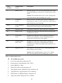
4. Testing the System
It is important to fully test the system after installation. CommPact has several testing
tools to verify that the system will operate optimally, including the wireless
communication
1.
2.
3.
Go to the main menu and press '√'
Enter engineer code
Decide which quick key should be selected as summarized in Table 10.
Quick
key
Option
Description and Notes
7>0>3
WL Sounder
Test
The external sounder is sounded briefly
7>0>4
Sounder Test
Built-in sounder is sounded briefly
7>0>6
Walk Test
A list of registered devices appears. Trigger each device;
when the system receives a successful transmission from a
device the device is removed from the list
7>0>7>
1
TX List
This test is a scrollable inventory of all registered devices and
their last reported status. Using the arrow buttons, scroll
through the devices list. The devices list displays the
zone/device number or descriptor.(Press the key to toggle
the display) , the signal strength of the last received
transmission and the last received status of the transmitter
7>9>1
GSM Signal
Strength
Display the signal strength of the cellular network. In severe
cases of low GSM signal consider using external GSM
antenna.
7>9>2
RF RSSI level
Measure the RF RSSI level (RF noise measured by the
systems' receiver). The result in levels from 1 to 9 is similar to
the level of detector transmitter's signal strength. It is
recommended that the gap between the RF noise level and
the TX signal strength be at least 2. For example, if the RF
RSSI level is 5 and the TX signal strength is 6, consider
relocation of the Control Panel or its peripherals, or use
Repeater (EL-2635).
5
Follow Me
Enter telephone number and perform a test to ensure follow
me is operating
6>1
View Event
Log
Displays the last 1022 events of the system. The event
displays type of event, event time and the zone number. In
addition it indicates if the event has been reported to the
CMS as follows: R: Report Sent, F: Report Failed, C: Report
Canceled, N: No Report, D: Disable – Not reported to CMS
Table 10: Quick key
15
Electronics Line 3000 Ltd. Limited Warranty
EL and its subsidiaries and affiliates ("Seller") warrants its products to be free from defects in
materials and workmanship under normal use for 24 months from the date of production.
Because Seller does not install or connect the product and because the product may be used in
conjunction with products not manufactured by the Seller, Seller cannot guarantee the
performance of the security system which uses this product. Sellers' obligation and liability
under this warranty is expressly limited to repairing and replacing, at Sellers option, within a
reasonable time after the date of delivery, any product not meeting the specifications. Seller
makes no other warranty, expressed or implied, and makes no warranty of merchantability or
of fitness for any particular purpose. In no case shall seller be liable for any consequential or
incidental damages for breach of this or any other warranty, expressed or implied, or upon
any other basis of liability whatsoever. Sellers obligation under this warranty shall not include
any transportation charges or costs of installation or any liability for direct, indirect, or not be
compromised or circumvented; that the product will prevent any persona; injury or property
loss by intruder, robbery, fire or otherwise; or that the product will in all cases provide
adequate warning or protection. Buyer understands that a properly installed and maintained
alarm may only reduce the risk of intruder, robbery or fire without warning, but is not
insurance or a guaranty that such will not occur or that there will be no personal injury or
property loss as a result. Consequently seller shall have no liability for any personal injury,
property damage or loss based on a claim that the product fails to give warning. However, if
seller is held liable, whether directly or indirectly, for any loss or damage arising from under
this limited warranty or otherwise, regardless of cause or origin, sellers maximum liability
shall not exceed the purchase price of the product, which shall be complete and exclusive
remedy against seller. No employee or representative of Seller is authorized to change this
warranty in any way or grant any other warranty.
WARNING: This product should be tested at least once a week.
CAUTION: Risk of explosion if battery is replaced by an incorrect type. Dispose of used
batteries according to local regulations.
Contacting Electronics Line 3000 Ltd.
International Headquarters:
Electronics Line 3000 Ltd.
14 Hachoma St., 75655
Rishon Le Zion, Israel
Tel: (+972-3) 963-7777
Fax: (+972-3) 961-6584
All rights reserved.
No part of this document may be reproduced in any form without prior written permission from
the publisher.
Electronics Line 3000 Ltd. 10/2012
5IN1909 B
16