1
Pressure transmitter
SITRANS P, DS III Series with HART
Operating Instructions· 09/2012
SITRANS
Answers for industry.
Introduction
1
Safety instructions
2
Description
3
Installing/mounting
4
Connecting
5
Operation
6
Operating functions through
HART
7
Functional safety
8
Commissioning
9
SITRANS
Pressure transmitter
SITRANS P, DS III series with HART
Operating Instructions
7MF4.33..
09/2012
A5E00047092-08
Service and maintenance
10
Technical data
11
Dimension drawings
12
Spare parts/accessories
13
Appendix
A
List of abbreviations
B
Legal information
Warning notice system
This manual contains notices you have to observe in order to ensure your personal safety, as well as to prevent
damage to property. The notices referring to your personal safety are highlighted in the manual by a safety alert
symbol, notices referring only to property damage have no safety alert symbol. These notices shown below are
graded according to the degree of danger.
DANGER
indicates that death or severe personal injury will result if proper precautions are not taken.
WARNING
indicates that death or severe personal injury may result if proper precautions are not taken.
CAUTION
indicates that minor personal injury can result if proper precautions are not taken.
NOTICE
indicates that property damage can result if proper precautions are not taken.
If more than one degree of danger is present, the warning notice representing the highest degree of danger will be
used. A notice warning of injury to persons with a safety alert symbol may also include a warning relating to property
damage.
Qualified Personnel
The product/system described in this documentation may be operated only by personnel qualified for the specific
task in accordance with the relevant documentation, in particular its warning notices and safety instructions. Qualified
personnel are those who, based on their training and experience, are capable of identifying risks and avoiding
potential hazards when working with these products/systems.
Proper use of Siemens products
Note the following:
WARNING
Siemens products may only be used for the applications described in the catalog and in the relevant technical
documentation. If products and components from other manufacturers are used, these must be recommended or
approved by Siemens. Proper transport, storage, installation, assembly, commissioning, operation and
maintenance are required to ensure that the products operate safely and without any problems. The permissible
ambient conditions must be complied with. The information in the relevant documentation must be observed.
Trademarks
All names identified by ® are registered trademarks of Siemens AG. The remaining trademarks in this publication
may be trademarks whose use by third parties for their own purposes could violate the rights of the owner.
Disclaimer of Liability
We have reviewed the contents of this publication to ensure consistency with the hardware and software described.
Since variance cannot be precluded entirely, we cannot guarantee full consistency. However, the information in
this publication is reviewed regularly and any necessary corrections are included in subsequent editions.
Siemens AG
Industry Sector
Postfach 48 48
90026 NÜRNBERG
GERMANY
Order number: A5E00047092
Ⓟ 10/2012 Technical data subject to change
Copyright © Siemens AG 2012.
All rights reserved
Table of contents
1
2
3
4
Introduction...................................................................................................................................................9
1.1
Purpose of this documentation......................................................................................................9
1.2
Product information.......................................................................................................................9
1.3
History...........................................................................................................................................9
1.4
Scope of the instructions.............................................................................................................10
1.5
Checking the consignment..........................................................................................................10
1.6
Transportation and storage.........................................................................................................11
1.7
Notes on warranty.......................................................................................................................11
Safety instructions......................................................................................................................................13
2.1
2.1.1
2.1.2
Precondition for use.....................................................................................................................13
Laws and directives.....................................................................................................................13
Conformity with European directives...........................................................................................13
2.2
Use in hazardous areas...............................................................................................................14
Description..................................................................................................................................................17
3.1
System configuration...................................................................................................................17
3.2
Application range.........................................................................................................................18
3.3
Structure......................................................................................................................................19
3.4
Nameplate layout.........................................................................................................................21
3.5
Measuring point label layout........................................................................................................22
3.6
3.6.1
3.6.2
3.6.3
3.6.3.1
3.6.3.2
3.6.3.3
3.6.3.4
3.6.3.5
3.6.3.6
3.6.3.7
Functional principle......................................................................................................................23
Overview of mode of operation....................................................................................................23
Operation of the electronics.........................................................................................................23
Measuring cell operation.............................................................................................................24
Measuring cell for gauge pressure..............................................................................................25
Measuring cell for differential pressure and flow rate..................................................................26
Measuring cell for level................................................................................................................27
Measuring cell for absolute pressure from the differential pressure series.................................28
Measuring cell for absolute pressure from the gauge pressure series........................................29
Measuring cell for gauge pressure, front-flush membrane..........................................................29
Measuring cell for absolute pressure, front-flush membrane......................................................30
3.7
Remote seal................................................................................................................................31
3.8
SIMATIC PDM.............................................................................................................................31
Installing/mounting......................................................................................................................................33
4.1
4.1.1
4.1.2
Basic safety instructions..............................................................................................................33
Installation location requirements................................................................................................37
Proper mounting..........................................................................................................................38
SITRANS P, DS III series with HART
Operating Instructions, 09/2012, A5E00047092-08
3
Table of contents
5
6
4
4.1.2.1
Incorrect mounting.......................................................................................................................38
4.2
Disassembly................................................................................................................................39
4.3
4.3.1
4.3.2
4.3.3
Installation (except level).............................................................................................................39
Instructions for installation (except level).....................................................................................39
Installation (except level).............................................................................................................40
Fastening.....................................................................................................................................41
4.4
4.4.1
4.4.2
4.4.3
"Level" installation.......................................................................................................................43
Instructions for level installation...................................................................................................43
Installation for level......................................................................................................................44
Connection of the negative pressure line....................................................................................45
4.5
4.5.1
4.5.2
"Remote seal" installation............................................................................................................47
Remote seal installation..............................................................................................................47
Installation of the remote seal with the capillary line...................................................................49
4.6
Turing the measuring cell against housing..................................................................................54
4.7
Rotating the display.....................................................................................................................55
Connecting..................................................................................................................................................57
5.1
5.1.1
Basic safety instructions..............................................................................................................57
Unsuitable cables and/or cable glands........................................................................................57
5.2
Connecting the device.................................................................................................................60
5.3
Connecting the Han plug.............................................................................................................62
5.4
Connecting the M12 connector....................................................................................................63
Operation....................................................................................................................................................65
6.1
Overview of operation..................................................................................................................65
6.2
Basic safety instructions..............................................................................................................66
6.3
Instructions for operation.............................................................................................................66
6.4
6.4.1
6.4.2
6.4.3
6.4.4
6.4.5
6.4.6
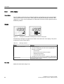
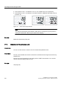
Display.........................................................................................................................................67
Display elements.........................................................................................................................67
Units display................................................................................................................................68
Error display................................................................................................................................69
Mode display...............................................................................................................................70
Status display..............................................................................................................................70
Overflow range............................................................................................................................71
6.5
6.5.1
6.5.2
6.5.3
6.5.3.1
6.5.3.2
6.5.3.3
6.5.4
6.5.5
6.5.5.1
6.5.5.2
6.5.5.3
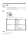
Local operation............................................................................................................................72
Local control elements.................................................................................................................72
Operation using buttons..............................................................................................................74
Start of scale value/full scale value.............................................................................................75
Difference between setting and adjusting....................................................................................75
Setting/adjusting the start of scale value.....................................................................................79
Setting/adjusting the full scale value...........................................................................................80
Setting/adjusting electrical damping............................................................................................82
Blind start of scale value/full scale value.....................................................................................83
Difference between setting/adjusting and blind setting/adjusting................................................83
Blind setting of start of scale value..............................................................................................84
Blind setting of full scale value....................................................................................................85
SITRANS P, DS III series with HART
Operating Instructions, 09/2012, A5E00047092-08
Table of contents
6.5.5.4
6.5.5.5
6.5.6
6.5.7
6.5.8
6.5.9
6.5.10
6.5.11
6.5.12
6.5.13
7
Blind adjusting of the start of scale value....................................................................................86
Blind adjustment of the full scale value.......................................................................................86
Trimming the zero point...............................................................................................................87
Current transmitter.......................................................................................................................88
Output current in case of fault.....................................................................................................89
buttons and function lock.............................................................................................................90
Releasing key lock or function lock.............................................................................................91
Flow rate measurement (only differential pressure)....................................................................91
Measured value display...............................................................................................................94
Unit..............................................................................................................................................95
Operating functions through HART.............................................................................................................99
7.1
Operating functions through HART communication....................................................................99
7.2
Process tag data........................................................................................................................100
7.3
7.3.1
7.3.2
7.3.3
7.3.4
7.3.5
7.3.6
7.3.7
7.3.8
7.3.9
7.3.10
7.3.11
Selecting the measuring modes................................................................................................100
Overview of measuring modes..................................................................................................100
Measuring mode selector..........................................................................................................101
Variable mapper........................................................................................................................101
Measuring mode "Pressure"......................................................................................................101
Customized characteristic curve................................................................................................102
Measuring mode "Level"............................................................................................................103
Measuring mode "Flow rate".....................................................................................................106
Measuring mode "User".............................................................................................................108
Measured value status..............................................................................................................110
Analog output............................................................................................................................114
Scaling the display value...........................................................................................................115
7.4
Setting zero point and limit point...............................................................................................116
7.5
Blind setting of zero point and limit point...................................................................................117
7.6
Zero point calibration (position correction)................................................................................117
7.7
Electrical damping.....................................................................................................................118
7.8
Fast response mode..................................................................................................................118
7.9
Current sensor...........................................................................................................................118
7.10
Fault current..............................................................................................................................118
7.11
Setting the current limits............................................................................................................119
7.12
Key lock and write protection.....................................................................................................120
7.13
Measured value display.............................................................................................................121
7.14
Selection of the physical unit.....................................................................................................122
7.15
Bar graph...................................................................................................................................123
7.16
7.16.1
7.16.2
Sensor calibration......................................................................................................................123
Sensor trim................................................................................................................................123
Trimming the sensor..................................................................................................................124
7.17
Current sensor trim....................................................................................................................124
7.18
Factory calibration.....................................................................................................................125
SITRANS P, DS III series with HART
Operating Instructions, 09/2012, A5E00047092-08
5
Table of contents
8
9
6
7.19
Static configuration data............................................................................................................126
7.20
Flow rate measurement (only differential pressure)..................................................................127
7.21
7.21.1
7.21.2
7.21.3
7.21.4
7.21.5
Diagnostic functions..................................................................................................................128
Overview....................................................................................................................................128
Operating hours counter............................................................................................................129
Calibration timer and service timer............................................................................................129
Min/max indicator......................................................................................................................130
Limit modules............................................................................................................................131
7.22
7.22.1
7.22.2
7.22.3
Simulation..................................................................................................................................133
Overview of simulation..............................................................................................................133
Simulation as fixed value...........................................................................................................134
Simulation with a ramp function.................................................................................................134
7.23
Limit monitor..............................................................................................................................134
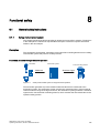
Functional safety.......................................................................................................................................137
8.1
8.1.1
8.1.2
General safety instructions........................................................................................................137
Safety-instrumented system......................................................................................................137
Safety Integrity Level (SIL)........................................................................................................138
8.2
8.2.1
8.2.2
8.2.3
8.2.4
8.2.5
8.2.6
Device-specific safety information for single-channel operation (SIL 2)....................................140
Safety function...........................................................................................................................140
Settings......................................................................................................................................140
Requirements ...........................................................................................................................141
Behavior in case of faults..........................................................................................................142
Maintenance/Checking..............................................................................................................142
Safety characteristics................................................................................................................142
8.3
8.3.1
8.3.2
8.3.3
8.3.4
8.3.5
8.3.6
Device-specific safety information for redundant operation (SIL 3)...........................................143
Safety function...........................................................................................................................143
Requirements ...........................................................................................................................144
Settings......................................................................................................................................145
Behavior in case of faults..........................................................................................................146
Maintenance/Checking..............................................................................................................146
Safety characteristics................................................................................................................147
8.4
8.4.1
8.4.2
Add-on parts..............................................................................................................................147
Checking a device with add-on pneumatic block.......................................................................148
Checking a device with add-on remote seal..............................................................................148
Commissioning.........................................................................................................................................149
9.1
Basic safety instructions............................................................................................................149
9.2
Introduction to commissioning...................................................................................................150
9.3
9.3.1
9.3.2
gauge pressure, absolute pressure from the differential pressure series and absolute pressure
from the gauge pressure series.................................................................................................151
Commissioning for gases..........................................................................................................151
Commissioning with steam or liquid..........................................................................................152
9.4
9.4.1
9.4.2
9.4.3
Differential pressure and flow rate.............................................................................................153
Safety notes for commissioning with differential pressure and flow rate...................................153
Commissioning in gaseous environments.................................................................................154
Commissioning for liquids..........................................................................................................155
SITRANS P, DS III series with HART
Operating Instructions, 09/2012, A5E00047092-08
Table of contents
9.4.4
10
11
12
13
A
Commissioning with vapor.........................................................................................................157
Service and maintenance.........................................................................................................................159
10.1
Basic safety instructions............................................................................................................159
10.2
10.2.1
10.2.2
10.2.3
10.2.4
Maintenance and repair work....................................................................................................162
Defining the maintenance interval.............................................................................................162
Checking the gaskets................................................................................................................163
Display in case of a fault............................................................................................................163
Changing the measuring cell and application electronics.........................................................164
10.3
10.3.1
Cleaning....................................................................................................................................164
Servicing the remote seal measuring system............................................................................165
10.4
Return procedure.......................................................................................................................166
10.5
Disposal.....................................................................................................................................166
Technical data..........................................................................................................................................169
11.1
Overview of technical data........................................................................................................169
11.2
Input point..................................................................................................................................170
11.3
Output........................................................................................................................................177
11.4
Measuring accuracy..................................................................................................................177
11.5
Operating conditions..................................................................................................................183
11.6
Construction..............................................................................................................................187
11.7
Display, keyboard and auxiliary power......................................................................................191
11.8
Certificates and approvals.........................................................................................................192
11.9
HART communication................................................................................................................194
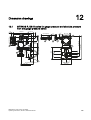
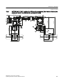
Dimension drawings.................................................................................................................................195
12.1
SITRANS P, DS III series for gauge pressure and absolute pressure from the gauge pressure
series.........................................................................................................................................195
12.2
SITRANS P, DS III series for differential pressure, flow rate and absolute pressure from the
differential pressure series........................................................................................................197
12.3
SITRANS P, DS III series for level............................................................................................200
12.4
12.4.1
12.4.2
12.4.3
12.4.4
12.4.5
SITRANS P, DS III series (flush mounted)................................................................................202
Note 3A and EHDG...................................................................................................................203
Connections as per EN and ASME...........................................................................................203
F&B and pharma flange.............................................................................................................204
PMC Style..................................................................................................................................208
Special connections...................................................................................................................209
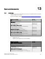
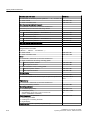
Spare parts/accessories...........................................................................................................................211
13.1
Order data.................................................................................................................................211
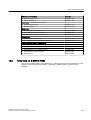
13.2
Order data for SIMATIC PDM....................................................................................................213
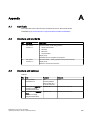
Appendix...................................................................................................................................................215
A.1
Certificate..................................................................................................................................215
SITRANS P, DS III series with HART
Operating Instructions, 09/2012, A5E00047092-08
7
Table of contents
B
A.2
Literature and standards............................................................................................................215
A.3
Literature and catalogs..............................................................................................................215
A.4
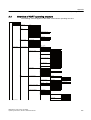
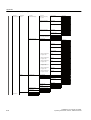
Overview of HART operating structure......................................................................................217
A.5
Technical support......................................................................................................................220
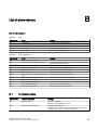
List of abbreviations..................................................................................................................................221
B.1
Functional safety.......................................................................................................................221
Glossary....................................................................................................................................................223
Index.........................................................................................................................................................227
8
SITRANS P, DS III series with HART
Operating Instructions, 09/2012, A5E00047092-08
1
Introduction
1.1
Purpose of this documentation
These instructions contain all information required to commission and use the device. It is your
responsibility to read the instructions carefully prior to installation and commissioning. In order
to use the device correctly, first review its principle of operation.
The instructions are aimed at persons mechanically installing the device, connecting it
electronically, configuring the parameters and commissioning it, as well as service and
maintenance engineers.
1.2
Product information
The programming manual is an integral part of the CD, which is either supplied or can be
ordered. The programming manual is also available on the Siemens homepage.
On the CD, you will also find the catalog extract with the ordering data, the Software Device
Install for SIMATIC PDM for additional installation, and the required software.
See also
Product information on SITRANS P in the Internet (http://www.siemens.com/sitransp)
Catalog process instrumentation (http://www.siemens.com/processinstrumentation/catalogs)
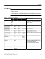
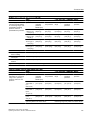
1.3
History
This history establishes the correlation between the current documentation and the valid
firmware of the device.
The documentation of this edition applies to the following firmware:
Edition
Firmware identifier nameplate
System integration
Installation path for PDM
09/2012
FW: 11.03.03, FW: 11.03.04,
FW: 11.03.05, FW: 11.03.06
PDM 6.0 ; Dev. Rev.3
DD Rev.2
SITRANS P DSIII.2
1)
1)
up to SP05 Hotfix 5
The most important changes in the documentation when compared with the respective
previous edition are given in the following table.
SITRANS P, DS III series with HART
Operating Instructions, 09/2012, A5E00047092-08
9
Introduction
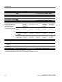
1.5 Checking the consignment
Edition
Remark
09/2012
The following chapters have been changed:
● "General safety notices" chapter
● "Mounting" chapter
● "Functional safety" chapter
● "Technical data" chapter
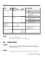
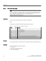
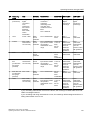
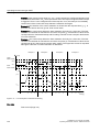
1.4
Scope of the instructions
Table 1-1
1.5
"7MF4.33" stands for:
Order number
SITRANS P, DS III series for
7MF4033
Gauge pressure
7MF4133
Gauge pressure, flush mounted diaphragm
7MF4233
Absolute pressure from the gauge pressure series
7MF4333
Absolute pressure from the differential pressure series
7MF4433
Differential pressure and flow rate, PN 32/160 (MAWP 464/2320 psi)
7MF4533
Differential pressure and flow rate, PN 420 (MAWP 6092 psi)
7MF4633
Level
Checking the consignment
1. Check the packaging and the device for visible damage caused by inappropriate handling
during shipping.
2. Report any claims for damages immediately to the shipping company.
3. Retain damaged parts for clarification.
4. Check the scope of delivery by comparing the shipping documents with your order for
correctness and completeness.
WARNING
Using a damaged or incomplete device
Danger of explosion in hazardous areas.
● Do not use any damaged or incomplete devices.
See also
Return procedure (Page 166)
10
SITRANS P, DS III series with HART
Operating Instructions, 09/2012, A5E00047092-08
Introduction
1.7 Notes on warranty
1.6
Transportation and storage
To guarantee sufficient protection during transport and storage, observe the following:
● Keep the original packaging for subsequent transportation.
● Devices/replacement parts should be returned in their original packaging.
● If the original packaging is no longer available, ensure that all shipments are properly
packaged to provide sufficient protection during transport. Siemens cannot assume liability
for any costs associated with transportation damages.
CAUTION
Insufficient protection during storage
The packaging only provides limited protection against moisture and infiltration.
● Provide additional packaging as necessary.
Special conditions for storage and transportation of the device are listed in "Technical data"
(Page 169).
1.7
Notes on warranty
The contents of this manual shall not become part of or modify any prior or existing agreement,
commitment or legal relationship. The sales contract contains all obligations on the part of
Siemens as well as the complete and solely applicable warranty conditions. Any statements
regarding device versions described in the manual do not create new warranties or modify the
existing warranty.
The content reflects the technical status at the time of publishing. Siemens reserves the right
to make technical changes in the course of further development.
SITRANS P, DS III series with HART
Operating Instructions, 09/2012, A5E00047092-08
11
Safety instructions
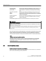
2.1
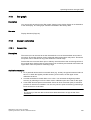
2
Precondition for use
This device left the factory in good working condition. In order to maintain this status and to
ensure safe operation of the device, observe these instructions and all the specifications
relevant to safety.
Observe the information and symbols on the device. Do not remove any information or symbols
from the device. Always keep the information and symbols in a completely legible state.
Symbol
Explanation
Consult operating instructions
2.1.1
Laws and directives
Observe the test certification, provisions and laws applicable in your country during connection,
assembly and operation. These include, for example:
● National Electrical Code (NEC - NFPA 70) (USA)
● Canadian Electrical Code (CEC) (Canada)
Further provisions for hazardous area applications are for example:
● IEC 60079-14 (international)
● EN 60079-14 (EC)
2.1.2
Conformity with European directives
The CE mark on the device is a sign of conformity with the following European directives:
SITRANS P, DS III series with HART
Operating Instructions, 09/2012, A5E00047092-08
13
Safety instructions
2.2 Use in hazardous areas
Electromagnetic
Compatibility EMC
2004/108/EC
Atmosphère explosible
ATEX
94/9/EC
Pressure Equipment
Directive PED
97/23/EC
Directive of the European Parliament and of the Council on the
approximation of the laws of the Member States relating to
electromagnetic compatibility and repealing Directive 89/336/
EEC.
Directive of the European Parliament and the Council on the
approximation of the laws of the Member States concerning
equipment and protective systems intended for use in potentially
explosive atmospheres.
Directive of the European Parliament and of the Council on the
approximation of the laws of the Member States concerning
pressure equipment.
The standards applied can be found in the EC declaration of conformity for the device.
WARNING
Improper device modifications
Danger to personnel, system and environment can result from modifications to the device,
particularly in hazardous areas.
● Only carry out modifications that are described in the instructions for the device. Failure
to observe this requirement cancels the manufacturer's warranty and the product
approvals.
Due to the large number of possible applications, each detail of the described device versions
for each possible scenario during commissioning, operation, maintenance or operation in
systems cannot be considered in the instructions. If you need additional information not
covered by these instructions, contact your local Siemens office or company representative.
Note
Operation under special ambient conditions
We highly recommend that you contact your Siemens representative or our application
department before you operate the device under special ambient conditions as can be
encountered in nuclear power plants or when the device is used for research and
development purposes.
2.2
Use in hazardous areas
Qualified personnel for hazardous area applications
Persons who install, assemble, commission, operate and service the device in a hazardous
area must have the following specific qualifications:
14
SITRANS P, DS III series with HART
Operating Instructions, 09/2012, A5E00047092-08
Safety instructions
2.2 Use in hazardous areas
● They are authorized, trained or instructed in operating and maintaining devices and systems
according to the safety regulations for electrical circuits, high pressures, aggressive and
hazardous media.
● They are authorized, trained, or instructed in carrying out work on electrical circuits for
hazardous systems.
● They are trained or instructed in maintenance and use of appropriate safety equipment
according to the pertinent safety regulations.
WARNING
Unsuitable device for the hazardous area
Danger of explosion.
● Only use equipment that is approved for use in the intended hazardous area and labelled
accordingly.
See also
Technical data (Page 169)
WARNING
Loss of safety of device with type of protection "Intrinsic safety Ex i"
If the device has already been operated in non-intrinsically safe circuits or the electrical
specifications have not been observed, the safety of the device is no longer ensured for use
in hazardous areas. There is a danger of explosion.
● Connect the device with type of protection "Intrinsic safety" solely to an intrinsically safe
circuit.
● Observe the specifications for the electrical data on the certificate and in Chapter
"Technical data (Page 169)".
SITRANS P, DS III series with HART
Operating Instructions, 09/2012, A5E00047092-08
15
Safety instructions
2.2 Use in hazardous areas
WARNING
Use of incorrect device parts in potentially explosive environments
Devices and their associated device parts are either approved for different types of protection
or they do not have explosion protection. There is a danger of explosion if device parts (such
as covers) are used for devices with explosion protection that are not expressly suited for
this type of protection. If you do not adhere to these guidelines, the test certificates and the
manufacturer warranty will become null and void.
● Use only device parts that have been approved for the respective type of protection in the
potentially explosive environment. Covers that are not suited for the "explosion-proof" type
of protection are identified as such by a notice label attached to the inside of the cover
with "Not Ex d Not SIL".
● Do not swap device parts unless the manufacturer specifically ensures compatibility of
these parts.
WARNING
Risk of explosion due to electrostatic charge
To prevent the build-up of an electrostatic charge in a hazardous area, the key cover must
be closed during operation and the screws tightened.
The key cover may be opened temporarily at any time for the purposes of operating the
transmitter, even during plant operation; the screws should then be tightened again.
NOTICE
Electrostatic-sensitive devices
The device contains electrostatic-sensitive devices (ESD). ESD can be destroyed by voltages
far too low to be detected by humans. These voltages can occur if you simply touch a
component part or the electrical connections of a module without being electrostatically
discharged. The damage to a module caused by overvoltage cannot normally be detected
immediately; it only becomes apparent after a longer period of operating time has elapsed.
Protective measures against the discharge of static electricity:
● Make sure that no power is applied.
● Before working with modules, make sure that you discharge static from your body, for
example by touching a grounded object.
● Devices and tools used must be free of static charge.
● Hold modules only by their edges.
● Do not touch connector pins or conductor tracks on a module with the ESD notice.
16
SITRANS P, DS III series with HART
Operating Instructions, 09/2012, A5E00047092-08
3
Description
3.1
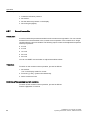
System configuration
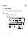
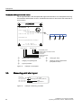
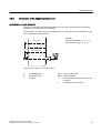
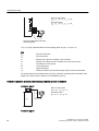
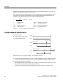
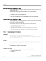
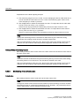
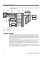
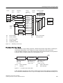
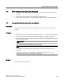
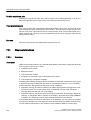
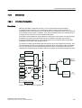
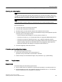
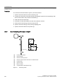
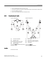
Overview
The pressure transmitter can be used in a number of system configurations:
● as a stand-alone version, supplied with the necessary auxiliary power
● as part of a complex system environment, e.g. SIMATIC S7
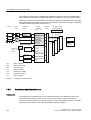
System communication
Communication is via the HART protocol, using:
● HART Communicator (load 230 ... 1100 Ω)
● PC with HART modem, on which appropriate software is installed, e.g. SIMATIC PDM (load
230 ... 500 Ω)
● Control system which can communicate via the HART protocol, e.g. SIMATIC PCS7
&RQWUROV\VWHP
6,0$7,&3'0
6
(70
RU
$
/RDG
7UDQVPLWWHU
+$57
&RPPXQLFDWRU
RU
+$57
0RGHP
56&
RU86%
Figure 3-1
$X[LOLDU\SRZHU
3&ODSWRSZLWK
6,0$7,&3'0
Possible system configurations
SITRANS P, DS III series with HART
Operating Instructions, 09/2012, A5E00047092-08
17
Description
3.2 Application range
3.2
Application range
Overview
Depending on the version, a transmitter measures corrosive, non-corrosive and hazardous
gases, vapors and liquids.
You can use the transmitter for the following types of measurement:
● Gauge pressure
● Absolute pressure
● Differential pressure
With appropriate parameter settings and the necessary add-on parts (e.g. flow orifices and
remote seals), the pressure transmitter can also be used for the following measurements:
● Level
● Volume
● Mass
● Volumetric flow
● Mass flow rate
The output signal is always a load-independent direct current between 4 and 20 mA.
You can install the "intrinsically-safe" or "explosion-proof" version of the transmitter in
hazardous areas. The devices have an EC type examination certificate and comply with the
appropriate harmonized European CENELEC directives.
Transmitters with remote seals of different shapes can be delivered for special applications.
For example, measuring high-viscosity substances is a special application.
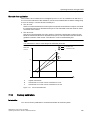
Gauge pressure
This version measures aggressive, non-aggressive and hazardous gases, vapors and liquids.
The smallest span is 0.01 bar g (0.145 psi g), and the largest 700 bar g (10153 psi g).
Differential pressure and flow rate
This version measures corrosive, non-corrosive and hazardous gases, vapors and liquids. You
can use this version for the following measurement types:
● differential pressure, e.g. effective differential pressure
● Gauge pressure, suitable for small positive or negative pressure value
● in combination with a restrictor device: flow rate q ~ ∆p
The smallest measuring span is 1 mbar (0.0145 psi), the largest 30 bar (435 psi).
18
SITRANS P, DS III series with HART
Operating Instructions, 09/2012, A5E00047092-08
Description
3.3 Structure
Level
This version with mounting flange measures the level of non-corrosive, corrosive and
hazardous liquids in open and closed containers. The smallest measuring span is 25 mbar
(0.363 psi), the largest 5 bar (72.5 psi). The nominal diameter of the mounting flange is DN 80
or DN 100 or 3" or 4".
The negative connection of the measuring cell is kept open when measuring the level of open
containers. This measurement is referred to as "measurement against atmosphere". The
negative connection is normally connected with the container when measuring the level of
closed containers. This balances the static pressure.
Wetted parts are made of various materials, depending on corrosion resistance requirements.
Absolute pressure
This version measures the absolute pressure of aggressive, non-aggressive and hazardous
gases, vapors and liquids.
There are two series: a "differential pressure" series and a "gauge pressure" series. The
"differential pressure" series is distinguished by a high overload capability.
The smallest measuring span of the "differential pressure" series is 8.3 mbar a (0.12 psi a),
and the largest is 100 bar a (1450 psi a).
The smallest measuring span of the "gauge pressure" series is 8.3 mbar a (0.12 psi a), and
the largest is 30 bar a (435 psi a).
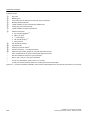
3.3
Structure
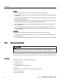
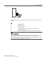
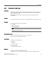
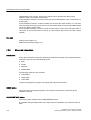
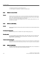
Depending on a customer-specific order, the device comprises different parts.
SITRANS P, DS III series with HART
Operating Instructions, 09/2012, A5E00047092-08
19
Description
3.3 Structure
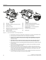
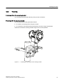
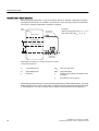
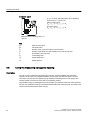
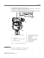
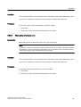
①
②
③
④
⑤
⑥
⑦
Key cover
Cover (front), optionally with inspection window
Display (optional)
Measuring point label
Retaining screw; twist proofing of the measuring cell
in relation to the electronics enclosure
Process connection
⑧
⑨
⑩
⑪
Cable inlet, optionally with cable gland
Cover (rear) for electrical terminal compartment
Electrical terminal compartment
Protective conductor connector/equipotential
bonding terminal
⑫
Nameplate (approval information)
⑬
Blanking plug
Nameplate (general information)
Figure 3-2
View of the transmitter: Left: Front right: Rear view
● The electronics enclosure is made of die cast aluminum or precision cast stainless steel.
● The housing has a removable circular cover at the front and the back.
● Depending on the device version, the front cover ② may be designed as an inspection
window. You can read the measured values straight off the digital display through this
inspection window.
● The cable inlet ⑧ to the electrical terminal compartment is at the side; either the left or
right-hand one can be used. The unused opening is closed with a blanking plug ⑬.
● The protective conductor terminal/equipotential bonding terminal ⑪ is located at the back
of the enclosure.
● The electrical terminal compartment ⑩ for the auxiliary power and shield is accessible
when you remove the back cover ⑨.
● The measuring cell with a process connection ⑥ is located in the lower section of the
enclosure. This measuring cell is secured against twisting by a retaining screw ⑤. Thanks
to the modular structure of the transmitter, the measuring cell, the electronic unit or the
network card can be replaced if required.
● On the upper face of the enclosure you can see crosshead screws which secure the key
cover ①, under which there are 3 keys for local operation.
20
SITRANS P, DS III series with HART
Operating Instructions, 09/2012, A5E00047092-08
Description
3.4 Nameplate layout
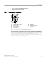
3.4
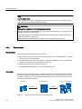
Nameplate layout
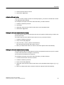
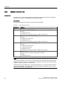
Nameplate with general information
The nameplate bearing the Order No. and other important information, such as design details
and technical data, is on the side of the enclosure.
D-761 81 K arlsr uhe
SITRANS
P
0 032
PED:SEP
Tr ansmit ter fo r pressur e
7MF4033-1EB1 0-1D A1
Fab. Nr. N1LN1 1-0 047 11
V H :DC1 0.5-45 V (not intr.s ave ) outp.:4-20 mA
F illing
Silik onöl
Mat.: Connec. Diaphr.
1.4404 2.481 9
Measuring span
Ove rrange limits
: 0.6 3 - 6 3 bar
: -1 - 100 bar
Type of protection IP 65
Made in Fr ance
①
Order number (machine-readable product
code)
Figure 3-3
②
Serial number
Example of a nameplate
SITRANS P, DS III series with HART
Operating Instructions, 09/2012, A5E00047092-08
21
Description
3.5 Measuring point label layout
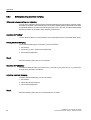
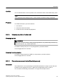
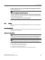
Nameplate with approval information
On the opposite side is the nameplate with approval information. This nameplate shows e.g.
the hardware and firmware versions. Certificate information is also listed if the transmitter is
an ex-version.
D-761 81 K arlsr uhe
SITRANS
II 1/2 G
P
E x d IIC T4/T6
V H :DC 10. 5 - 4 5 V outp.: 4 - 2 0 m A
,,*([G,,&77
PTB 99 ATEX 1160
Observ e EC-T ype Examination Cer tificate !
T a = -40 ... 85/60 °C
FW : 1 3.0 1.02 HW : 01.02.03
):[[\\]]
+:[[\\]]
&RPSDWLELOLW\PDUN
3URGXFWYHUVLRQFRQQHFWLRQERDUG
6HULDOQXPEHU
):YHUVLRQ
'RFXPHQW5HYLVLRQ
'HYLFHW\SH
①
②
Category for operating area
③
Type of protection
Characteristics for hazardous area
Figure 3-4
3.5
Group (gas, dust)
Maximum surface temperature
(temperature class)
Example of a nameplate
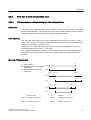
Measuring point label layout
Y01 or Y02
= max. 27 char.
Y15 = max. 16 char.
Y99 = max. 10 char.
Y16 = max. 27 char.
Figure 3-5
22
④
⑤
.... to .... mbar
Measuring point number (TAG No.)
1234
Measuring point text
Example of measuring point label
SITRANS P, DS III series with HART
Operating Instructions, 09/2012, A5E00047092-08
Description
3.6 Functional principle
3.6
Functional principle
3.6.1
Overview of mode of operation
This chapter describes how the transmitter works.
First the electronics are described, and then the physical principle of the sensors which are
used with the various device versions for the individual measurement types.
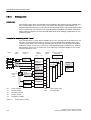
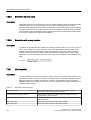
3.6.2
Operation of the electronics
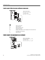
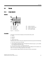
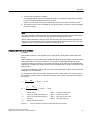
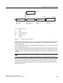
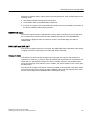
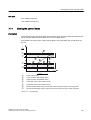
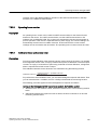
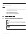
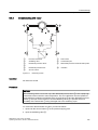
Description
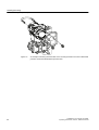
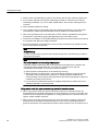
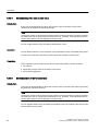
6,(0(16
((3520
$
&
'
'
&
,$
8+
$
①
②
③
④
⑤
⑥
((3520
6HQVRU
6HQVRUV
+$57PRGHP
((3520
(OHFWU
0HDVXULQJFHOOHOHFWURQLFV
$SSOLFDWLRQHOHFWURQLFV
Measuring cell sensor
⑦
⑧
⑨
⑩
Measuring amplifier
Analog-to-digital converter
Microcontroller
HART modem
Buttons (local operation)
Display
Connection for external ammeter
Digital-to-analog converter
IA
Output current
Each with an EEPROM in the measuring cell
and in the electronics
UH
Auxiliary power
Figure 3-6
Operation of the electronics with HART communication
SITRANS P, DS III series with HART
Operating Instructions, 09/2012, A5E00047092-08
23
Description
3.6 Functional principle
Function
● The input pressure is converted into an electrical signal by the sensor ①.
● This signal is amplified by the measuring amplifier ② and digitized in an analog-to-digital
converter ③.
● The digital signal is analyzed in a microcontroller ④ and corrected with regard to linearity
and thermal characteristics.
● The digital signal is then converted in a digital-to-analog converter ⑤ into the output current
of 4 to 20 mA. A diode circuit provides reverse voltage protection.
● You can make an uninterrupted current measurement with a low resistance ammeter at
the connection ⑩.
● The measuring cell-specific data, electronics data and parameter assignment data are
saved in two EEPROMs ⑥. The first memory is linked to the measuring cell, the second
to the electronics.
Operation
● The buttons ⑧ can be used to call up individual functions, so-called modes.
● If you have a device with a display ⑨, you can use it to track the mode settings and other
device messages.
● The basic mode settings can be changed with a computer and HART modem ⑦ via PDM.
3.6.3
Measuring cell operation
CAUTION
If the measurement signal fails because of sensor breakage, the seal diaphragm may also
be destroyed. In the worst case scenario, the process medium leaks from the reference
pressure opening in the devices used for gauge pressure with a measuring span of ≤ 63 bar.
In the following sections, the process variable to be measured is called general inlet pressure.
Overview
The following modes of operation are described:
● Gauge pressure
● Absolute pressure
● Differential pressure and flow rate
● Level
The following process connections are available, for example:
● G1/2 B, 1/2-14 NPT
● Male thread: M20
24
SITRANS P, DS III series with HART
Operating Instructions, 09/2012, A5E00047092-08
Description
3.6 Functional principle
● Flange connection in accordance with EN 61518
● Flush-mounted process connections
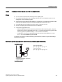
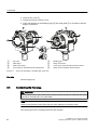
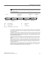
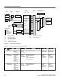
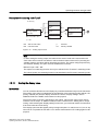
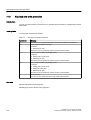
3.6.3.1
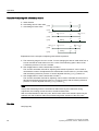
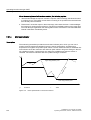
Measuring cell for gauge pressure
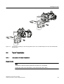
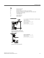
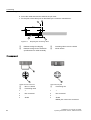
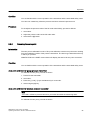
SH
①
②
③
④
Measuring cell
⑤
⑥
Gauge pressure sensor
Process connection
pe
Inlet pressure
Reference pressure opening
Filling liquid
Seal diaphragm
Figure 3-7
Function chart of measuring cell for gauge pressure
The inlet pressure (pe) is transferred to the gauge pressure sensor ⑥ via the seal diaphragm
④ and the fill fluid ⑤, displacing its measuring diaphragm. The displacement changes the
resistance of the four piezoresistors (bridge circuit) of the gauge pressure sensor. The change
in the resistance causes a bridge output voltage proportional to the inlet pressure.
Transmitters with measuring span ≤ 63 bar measure the inlet pressure against atmosphere,
those with measuring spans ≥ 160 bar against vacuum.
SITRANS P, DS III series with HART
Operating Instructions, 09/2012, A5E00047092-08
25
Description
3.6 Functional principle
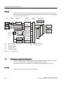
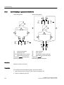
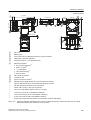
3.6.3.2
Measuring cell for differential pressure and flow rate
①
②
③
④
⑤
Inlet pressure P+
Pressure cap
O-ring
Measuring cell body
⑥
⑦
⑧
⑨
Overload diaphragm
Filling liquid
Seal diaphragm
Inlet pressure P-
Differential pressure sensor
Figure 3-8
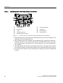
Function chart of the measuring cell for differential pressure and flow rate
● Differential pressure is transmitted to the differential pressure sensor ⑤ through the seal
diaphragms ⑧ and the filling liquid ⑦.
● When measuring limits are exceeded, the seal diaphragm ⑧ is displaced until the seal
diaphragm ② rests on the measuring cell body ④. The differential pressure sensor ⑤ is
thus protected against overloading since no further deflection of the overload diaphragm
⑥ is possible.
● The seal diaphragm ⑧ is displaced by the differential pressure. The displacement changes
the resistance of the four piezoresistors (bridge circuit) of the differential pressure sensor.
● The change in the resistance causes a bridge output voltage proportional to the differential
pressure.
26
SITRANS P, DS III series with HART
Operating Instructions, 09/2012, A5E00047092-08
Description
3.6 Functional principle
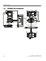
3.6.3.3
Measuring cell for level
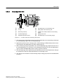
①
②
③
④
⑤
Pressure cap
O-ring
Measuring cell body
Overload diaphragm
Differential pressure sensor
Figure 3-9
⑥
⑦
⑧
⑨
⑩
Seal diaphragm on the measuring cell
Filling liquid of the measuring cell
Capillary tube with the fill fluid of the mounting
flange
Flange with a tube
Seal diaphragm on the mounting flange
Function chart of the measuring cell for level
● The inlet pressure (hydrostatic pressure) works hydraulically on the measuring cell through
the seal diaphragm ⑩ on the mounting flange ⑩.
● Differential pressure at the measuring cell is transmitted to the differential pressure sensor
⑤ through the seal diaphragms ⑥ and the filling liquid ⑦.
● When measuring limits are exceeded, the overload diaphragm ④ is displaced until one of
the seal diaphragms ⑥ or ⑩ rests on the measuring cell body ③. The seal diaphragms
⑥ thus protect the differential pressure sensor ⑤ from overload.
● The seal diaphragm ⑥ is displaced by the differential pressure. The displacement changes
the resistance of the four doped piezoresistors in the bridge circuit.
● The change in the resistance causes a bridge output voltage proportional to the differential
pressure.
SITRANS P, DS III series with HART
Operating Instructions, 09/2012, A5E00047092-08
27
Description
3.6 Functional principle
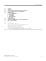
3.6.3.4
Measuring cell for absolute pressure from the differential pressure series
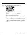
SH
①
②
③
④
⑤
Measuring cell filling liquid
O-ring
⑥
⑦
⑧
Measuring cell body
pe
Pressure input variable
Pressure cap
Seal diaphragm on the measuring cell
Overload diaphragm
Reference pressure
Absolute pressure sensor
Figure 3-10
Function chart of measuring cell for absolute pressure
● Absolute pressure is transmitted to the absolute pressure sensor ⑤ through the seal
diaphragm ② and the filling liquid ⑦.
● When measuring limits are exceeded, the overload diaphragm ⑥ is displaced until the seal
diaphragm ② rests on the measuring cell body ④. The seal diaphragm thus protects the
absolute pressure sensor ⑤ from overload.
● The difference between the inlet pressure (pe) and the reference pressure ⑧ on the
negative side of the measuring cell displaces the seal diaphragm ②. The displacement
changes the resistance of the four piezoresistors (bridge circuit) of the absolute pressure
sensor.
28
SITRANS P, DS III series with HART
Operating Instructions, 09/2012, A5E00047092-08
Description
3.6 Functional principle
● The change in the resistance causes a bridge output voltage proportional to the absolute
pressure.
3.6.3.5
Measuring cell for absolute pressure from the gauge pressure series
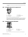
SH
①
②
③
④
⑤
⑥
Measuring cell
Process connection
Seal diaphragm
Figure 3-11
Filling liquid
Absolute pressure sensor
Inlet pressure
Function chart of measuring cell for absolute pressure
The inlet pressure (pe) is transferred to the absolute pressure sensor ⑤ via the seal diaphragm
③ and the fill fluid ④, displacing its measuring diaphragm. The displacement changes the
resistance of the four piezoresistors (bridge circuit) of the absolute pressure sensor. The
change in the resistance causes a bridge output voltage proportional to the inlet pressure.
3.6.3.6
Measuring cell for gauge pressure, front-flush membrane
SH
①
②
③
④
Measuring cell
⑤
⑥
Gauge pressure sensor
Process connection
pe
Inlet pressure
Reference pressure opening
Filling liquid
Seal diaphragm
Figure 3-12
Function chart of the measuring cell for gauge pressure, flush mounted diaphragm
SITRANS P, DS III series with HART
Operating Instructions, 09/2012, A5E00047092-08
29
Description
3.6 Functional principle
The inlet pressure (pe) is transferred to the gauge pressure sensor ⑥ via the seal diaphragm
④ and the filling liquid ⑤, displacing its measuring diaphragm. The displacement changes
the resistance of the four piezoresistors (bridge circuit) of the gauge pressure sensor. The
change in the resistance causes a bridge output voltage proportional to the inlet pressure.
Transmitters with measuring span ≤ 63 bar measure the inlet pressure against atmosphere,
those with measuring spans ≥ 160 bar against vacuum.
3.6.3.7
Measuring cell for absolute pressure, front-flush membrane
SH
①
②
③
Process connection
④
⑤
Absolute pressure sensor
Seal diaphragm
pe
Inlet pressure
Measuring cell
Figure 3-13
Filling liquid
Function chart of the measuring cell for absolute pressure, flush mounted diaphragm
The inlet pressure (pe) is transferred to the absolute pressure sensor ⑤ via the seal diaphragm
③ and the filling liquid ④, and displaces its measuring diaphragm. The displacement changes
the resistance of the four piezoresistors (bridge circuit) of the absolute pressure sensor. The
change in the resistance causes a bridge output voltage proportional to the inlet pressure.
30
SITRANS P, DS III series with HART
Operating Instructions, 09/2012, A5E00047092-08
Description
3.8 SIMATIC PDM
3.7
Remote seal
Product description
● A remote seal measuring system comprises the following elements:
– Remote seal
– Transmission line, e.g. capillary line
– Measuring device
Note
Malfunction of the remote seal measuring system
If you separate the components of the remote seal measuring system, this results in
malfunctioning of the system.
Do not separate the components under any circumstances.
● The measuring system based on a hydraulic principle is used to transfer pressure.
● The capillary line and the remote seal diaphragm are the most sensitive components in the
remote seal measuring system. The material thickness of the remote seal diaphragm is
only ∼ 0.1 mm.
● The smallest of leakages in the transmission system leads to the loss of transmission fluid.
● The loss of transmission fluid results in inaccuracies in the measurement and failure of the
measuring system.
● In order to avoid leaks and measuring errors, please observe the installation and
maintenance instructions in addition to the safety notes.
3.8
SIMATIC PDM
SIMATIC PDM is a software package for configuring, parameter assignment, commissioning,
diagnostics and maintenance of this device and other process devices.
SIMATIC PDM offers simple monitoring of process values, alarms, and device status
information of the transmitter.
SIMATIC PDM allows the process device data to be:
● displayed
● set
● modified
● saved
● diagnosed
● checked for plausibility
● managed
● simulated
SITRANS P, DS III series with HART
Operating Instructions, 09/2012, A5E00047092-08
31
Installing/mounting
4.1
4
Basic safety instructions
WARNING
Wetted parts unsuitable for the process media
Danger of injury or damage to device.
Hot, toxic and corrosive media could be released if the process medium is unsuitable for the
wetted parts.
● Ensure that the material of the device parts wetted by the process medium is suitable for
the medium. Refer to the information in "Technical data" (Page 169).
WARNING
Incorrect material for the diaphragm in Zone 0
Danger of explosion in the hazardous area. In the case of operation with intrinsically safe
supply units of category "ib" or devices of the flameproof enclosure version "Ex d" and
simultaneous use in Zone 0, transmitter explosion protection depends on the tightness of the
diaphragm.
● Ensure that the material used for the diaphragm is suitable for the process medium. Refer
to the information in the section "Technical data (Page 169)".
WARNING
Unsuitable connecting parts
Danger of injury or poisoning.
In case of improper mounting hot, toxic and corrosive process media could be released at
the connections.
● Ensure that connecting parts (such as flange gaskets and bolts) are suitable for connection
and process media.
SITRANS P, DS III series with HART
Operating Instructions, 09/2012, A5E00047092-08
33
Installing/mounting
4.1 Basic safety instructions
Note
Material compatibility
Siemens can provide you with support concerning selection of sensor components wetted
by process media. However, you are responsible for the selection of components. Siemens
accepts no liability for faults or failures resulting from incompatible materials.
WARNING
Exceeded maximum permissible operating pressure
Danger of injury or poisoning.
The maximum permissible operating pressure depends on the device version. The device
can be damaged if the operating pressure is exceeded. Hot, toxic and corrosive process
media could be released.
● Make sure that the device is suitable for the maximum permissible operating pressure of
your system. Refer to the information on the nameplate and/or in "Technical data
(Page 169)".
WARNING
Exceeded maximum ambient or process media temperature
Danger of explosion in hazardous areas.
Device damage.
● Make sure that the maximum permissible ambient and process media temperatures of
the device are not exceeded. Refer to the information in Chapter "Technical data
(Page 169)".
WARNING
Open cable inlet or incorrect cable gland
Danger of explosion in hazardous areas.
● Close the cable inlets for the electrical connections. Only use cable glands or plugs which
are approved for the relevant type of protection.
34
SITRANS P, DS III series with HART
Operating Instructions, 09/2012, A5E00047092-08
Installing/mounting
4.1 Basic safety instructions
WARNING
Incorrect conduit system
Danger of explosion in hazardous areas as result of open cable inlet or incorrect conduit
system.
● In the case of a conduit system, mount a spark barrier at a defined distance from the
device input. Observe national regulations and the requirements stated in the relevant
approvals.
See also
Technical data (Page 169)
WARNING
Incorrect mounting at Zone 0
Danger of explosion in hazardous areas.
● Ensure sufficient tightness at the process connection.
● Observe the standard IEC/EN 60079-14.
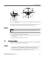
WARNING
Danger with "flameproof enclosure" protection
Danger of explosion in hazardous areas. An explosion may be caused by hot gas escaping
from the flameproof enclosure if there is too little space between it and the fixed parts.
● Ensure that there is a space of at least 40 mm between the flameproof joint and the fixed
parts.
①
Flameproof joint
SITRANS P, DS III series with HART
Operating Instructions, 09/2012, A5E00047092-08
35
Installing/mounting
4.1 Basic safety instructions
WARNING
Loss of explosion protection
Danger of explosion in hazardous areas if the device is open or not properly closed.
● Close the device as described in Chapter "Connecting the device (Page 60)".
WARNING
Use of incorrect device parts in potentially explosive environments
Devices and their associated device parts are either approved for different types of protection
or they do not have explosion protection. There is a danger of explosion if device parts (such
as covers) are used for devices with explosion protection that are not expressly suited for
this type of protection. If you do not adhere to these guidelines, the test certificates and the
manufacturer warranty will become null and void.
● Use only device parts that have been approved for the respective type of protection in the
potentially explosive environment. Covers that are not suited for the "explosion-proof" type
of protection are identified as such by a notice label attached to the inside of the cover
with "Not Ex d Not SIL".
● Do not swap device parts unless the manufacturer specifically ensures compatibility of
these parts.
CAUTION
Hot surfaces resulting from hot process media
Danger of burns resulting from surface temperatures above 70 °C (155 °F).
● Take appropriate protective measures, for example contact protection.
● Make sure that protective measures do not cause the maximum permissible ambient
temperature to be exceeded. Refer to the information in Chapter "Technical data
(Page 169)".
CAUTION
External stresses and loads
Damage to device by severe external stresses and loads (e.g. thermal expansion or pipe
tension). Process media can be released.
● Prevent severe external stresses and loads from acting on the device.
36
SITRANS P, DS III series with HART
Operating Instructions, 09/2012, A5E00047092-08
Installing/mounting
4.1 Basic safety instructions
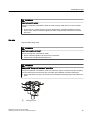
4.1.1
Installation location requirements
WARNING
Insufficient air supply
The device may overheat if there is an insufficient supply of air.
● Install the device so that there is sufficient air supply in the room.
● Observe the maximum permissible ambient temperature. Refer to the information in the
section "Technical data (Page 169)".
CAUTION
Aggressive atmospheres
Damage to device through penetration of aggressive vapors.
● Ensure that the device is suitable for the application.
NOTICE
Direct sunlight
Increased measuring errors.
● Protect the device from direct sunlight.
Make sure that the maximum ambient temperature is not exceeded. Refer to the information
in the section Technical data (Page 169).
SITRANS P, DS III series with HART
Operating Instructions, 09/2012, A5E00047092-08
37
Installing/mounting
4.1 Basic safety instructions
4.1.2
Proper mounting
4.1.2.1
Incorrect mounting
NOTICE
Incorrect mounting
The device can be damaged, destroyed, or its functionality impaired through improper
mounting.
● Before installing ensure there is no visible damage to the device.
● Make sure that process connectors are clean, and suitable gaskets and glands are used.
● Mount the device using suitable tools. Refer to the information in Chapter "Technical
data (Page 169)", for example installation torques requirements.
CAUTION
Loss of degree of protection
Damage to device if the enclosure is open or not properly closed. The degree of protection
specified on the nameplate or in Chapter "Technical data (Page 169)" is no longer guaranteed.
● Make sure that the device is securely closed.
See also
Connecting the device (Page 60)
38
SITRANS P, DS III series with HART
Operating Instructions, 09/2012, A5E00047092-08
Installing/mounting
4.3 Installation (except level)
4.2
Disassembly
WARNING
Incorrect disassembly
The following dangers may result through incorrect disassembly:
- Injury through electric shock
- Danger through emerging media when connected to the process
- Danger of explosion in hazardous area
In order to disassemble correctly, observe the following:
● Before starting work, make sure that you have switched off all physical variables such as
pressure, temperature, electricity etc. or that they have a harmless value.
● If the device contains dangerous media, it must be emptied prior to disassembly. Make
sure that no environmentally hazardous media are released.
● Secure the remaining connections so that no damage can result if the process is started
unintentionally.
4.3
Installation (except level)
4.3.1
Instructions for installation (except level)
Conditions
Note
Compare the desired operating data with the data on the nameplate.
Please also refer to the information on the remote seal if this is fitted.
Note
Protect the transmitter against:
● Direct heat radiation
● Rapid temperature fluctuations
● Heavy contamination
● Mechanical damage
● Direct sunlight
The installation location is to be as follows:
SITRANS P, DS III series with HART
Operating Instructions, 09/2012, A5E00047092-08
39
Installing/mounting
4.3 Installation (except level)
● Easily accessible
● As close as possible to the measuring point
● Vibration-free
● Within the permitted ambient temperature values
Installation configuration
The transmitter may in principle be configured above or below the pressure tapping point. The
recommended configuration depends on the aggregate state of the medium.
Installation configuration for gases
Install the transmitter above the pressure tapping point.
Lay the pressure tubing with a constant gradient to the pressure tapping point, so that any
condensation produced can drain in the main line and thereby avoid corruption of the measured
values.
Installation configuration for vapor and liquid
Install the transmitter below the pressure tapping point.
Lay the pressure tubing with a constant gradient to the pressure tapping point so that any gas
pockets can escape in the main line.
4.3.2
Installation (except level)
Note
Damage to measuring cell
When installing the process connection of the pressure transmitter, do not rotate the housing.
Rotating the housing may damage the measuring cell.
To avoid damage to the device, tighten the threaded nuts of the measuring cell using a wrench.
Procedure
Attach the transmitter to the process connection with an appropriate tool.
See also
Introduction to commissioning (Page 150)
40
SITRANS P, DS III series with HART
Operating Instructions, 09/2012, A5E00047092-08
Installing/mounting
4.3 Installation (except level)
4.3.3
Fastening
Fastening without the mounting bracket
You can fasten the transmitter directly on the process connection.
Fastening with the mounting bracket
You can fasten the mounting bracket as follows:
● On a wall or a mounting frame using two screws
● On a vertical or horizontal mounting tube (Ø 50 to 60 mm) using a tube bracket
Fasten the transmitter mounting bracket using the two screws provided.
Figure 4-1
Fastening the transmitter on the mounting bracket
SITRANS P, DS III series with HART
Operating Instructions, 09/2012, A5E00047092-08
41
Installing/mounting
4.3 Installation (except level)
Figure 4-2
42
An example of fastening the transmitter on the mounting bracket in the case of differential
pressure and horizontal differential pressure lines
SITRANS P, DS III series with HART
Operating Instructions, 09/2012, A5E00047092-08
Installing/mounting
4.4 "Level" installation
Figure 4-3
An example of fastening on the mounting bracket in the case of differential pressure and vertical differential
pressure lines
4.4
"Level" installation
4.4.1
Instructions for level installation
Requirements
Note
Compare the desired operating data with the data on the nameplate.
Please also refer to the information on the remote seal if this is fitted.
SITRANS P, DS III series with HART
Operating Instructions, 09/2012, A5E00047092-08
43
Installing/mounting
4.4 "Level" installation
Note
Protect the transmitter from:
● Direct heat
● Rapid temperature changes
● Severe soiling
● Mechanical damage
● Direct sunlight
Note
Select the height of the mounting flange such that the pressure transmitter is always mounted
below the lowest fill height to be measured.
The installation location is to be as follows:
● Easily accessible
● The measuring point must be as close as possible
● Vibration-free
● Within the permitted ambient temperature values
4.4.2
Installation for level
Note
Seals are required for the installation. The seals must be compatible with the medium to be
measured.
Seals are not included in the delivery.
Procedure
To install the transmitter for level, proceed as follows:
1. Attach the seal to the container's mating flange.
Ensure that the seal is centrically positioned and that it does not restrict the movement of
the flange's seal diaphragm in any way as otherwise the tightness of the process connection
is not guaranteed.
2. Screw on the transmitter's flange.
3. Observe the installation position.
44
SITRANS P, DS III series with HART
Operating Instructions, 09/2012, A5E00047092-08
Installing/mounting
4.4 "Level" installation
4.4.3
Connection of the negative pressure line
Assembly on an open container
A line is not required when taking measurements in an open container since the negative
chamber is connected with the atmosphere.
Ensure that no dirt enters the open connection ports, for example by using connection screws
with a 7MF4997-1CP bleed valve.
Formula:
Start of scale value: pMA = ρ · g · hU
Full-scale value: pME = ρ · g · hO
)XOOVFDOHYDOXH
K2
6WDUWRIVFDOHYDOXH
K8
+
Measurement assembly on an open container
hU
hO
p
Lower filling level
Upper filling level
Pressure
ΔpMA
ΔpME
ρ
g
SITRANS P, DS III series with HART
Operating Instructions, 09/2012, A5E00047092-08
Start of scale value
Full-scale value
Density of the measured medium in the
container
Acceleration due to gravity
45
Installing/mounting
4.4 "Level" installation
Assembly on a closed container
When taking measurements in a closed container without or with little condensate formation,
the negative pressure line is not filled. Lay the line in such a way that pockets of condensate
do not form. Install a condensation container if required.
6WDWLF
SUHVVXUH
Formula:
Start-of-scale value: ΔpMA = ρ · g · hU
Full-scale value: ΔpME = ρ · g · hO
*DVILOOHGORZ
SUHVVXUHOLQH
0D[LPXPOHYHO
)XOOVFDOHYDOXH
6WDUWRIVFDOHYDOXH
K2
K8
7UDQVPLWWHU
UHIHUHQFHOLQH
Measurement assembly on a closed container (no or little
condensate separation)
hU
hO
p
Lower filling level
Upper filling level
Pressure
ΔpMA
ΔpME
ρ
g
Start of scale value
Full-scale value
Density of the measured medium in the
container
Acceleration due to gravity
When taking measurements in a closed container with strong condensate formation, you must
fill the negative pressure line (mostly with the condensate of the measured medium) and install
a condensate pot. You can cut off the device using the dual pneumatic block 7MF9001-2.
46
SITRANS P, DS III series with HART
Operating Instructions, 09/2012, A5E00047092-08
Installing/mounting
4.5 "Remote seal" installation
6WDWLF
SUHVVXUH
Formula:
Start-of-scale value:
ΔpMA = g · (hU · ρ- hV · ρ')
Full-scale value:
ΔpMA = g · (hO · ρ- hV · ρ')
&RQVWDQW
FRPSDULVRQ
OHYHO
0D[LPXPOHYHO
)XOOVFDOHYDOXH
6WDUWRIVFDOHYDOXH
K2
/LTXLGILOOHG
ORZSUHVVXUHOLQH
KY
'
K8
7UDQVPLWWHU
UHIHUHQFHOLQH
-
Measurement assembly on a closed container (strong condensate
formation)
hU
hO
hV
Lower filling level
Upper filling level
Gland distance
ΔpMA
ΔpME
ρ
p
Pressure
ρ'
g
Start of scale value
Full-scale value
Density of the measured medium in the
container
Density of fluid in the negative pressure
line corresponds to the prevailing
temperature there
Acceleration due to gravity
The process connection on the negative side is a female thread 1/4-18 NPT or an oval flange.
Lay the line for the negative pressure using a seamless steel tube 12 mm x 1.5 mm.
4.5
"Remote seal" installation
4.5.1
Remote seal installation
General installation instructions
● Keep the measuring system in the factory packing until it is installed in order to protect it
from mechanical damage.
● When removing from the factory packing and installing: ensure that damage to and
mechanical deformations in the membrane are prevented.
SITRANS P, DS III series with HART
Operating Instructions, 09/2012, A5E00047092-08
47
Installing/mounting
4.5 "Remote seal" installation
● Never loosen the sealed filling screws on the remote seal and the measuring instrument.
● Do not cause damage to the remote separating membrane; scratches on the remote
separating membrane, e.g. due to sharp-edged objects, are the main starting points for
corrosion.
● Select suitable gaskets for sealing.
● Use a gasket having an adequately large inner diameter for flanging. Insert the gasket
concentrically; contact with the membrane leads to deviations in measurements.
● When using gaskets made of soft materials or PTFE: follow the guidelines of the gasket
manufacturer, especially regarding the tightening torque and setting cycles.
● At the time of installation, use suitable fastening components such as screws and nuts that
are compliant with fitting and flange standards.
● Excessive tightening of screwed joints on the process connection may displace the zero
point on the pressure transmitter.
Note
Commissioning
If a shut-off valve exists, open the shut-off valve slowly when commissioning in order to
avoid pressure surges.
Note
Permissible ambient and operating temperatures
Install the pressure measuring device such that the permissible limits of ambient and
measured medium temperatures are not overshot or undershot even with the
consideration of the effect of convection and heat radiation.
● Note the effect of temperature on the measuring accuracy.
● When selecting the remote seals, ensure that fittings and flange components have
adequate pressure-temperature resistance by selecting suitable materials and
pressure ratings. The pressure rating specified on the remote seal applies to reference
conditions according to IEC 60770.
● For the maximum permissible pressure at higher temperatures, please refer to the
standard specified on the remote seal.
Using remote seals with pressure measuring device for hazardous areas:
● When using remote seals with pressure measuring device for hazardous areas, the
permissible limits of ambient temperatures for the transmitter must not be exceeded. Hot
surfaces on the cooling section (capillaries or cooling elements) are a possible source of
ignition. Initiate suitable measures.
● When remote seals with a flame arrestor are used, the pressure measuring instrument
determines the permissible ambient temperature. In the case of potentially explosive
gaseous atmosphere, the temperature around the flame arrestor must not exceed +60 °C.
48
SITRANS P, DS III series with HART
Operating Instructions, 09/2012, A5E00047092-08
Installing/mounting
4.5 "Remote seal" installation
4.5.2
Installation of the remote seal with the capillary line
Notes
● Do not rest the measurement assembly on the capillary line.
● Do not bend capillary lines; risk of leakages and/or risk of considerable increase in the
setting time of the measuring system.
● Owing to the risk of bending and breakages, pay attention to mechanical overloads at the
joints such as capillary line-remote seal and capillary line-measuring device.
● Unwinding the excess capillary lines with a radius of at least 150 mm.
● Fasten the capillary line such that there are no vibrations.
● Permissible height differences:
– When installing the pressure measuring device above the measuring point, keep the
following in mind: the height difference of H1max. for remote seal measuring systems with
silicone, glycerin or paraffin oil filling. = 7 m must not be exceeded.
– If halocarbon oil is used as the filling liquid, this maximum height difference is only
H1max. = 4 m, see installation types A and B.
If negative overpressure is observed during measurements, reduce the permissible height
difference accordingly.
Installation type for gauge pressure and level measurements (open containers)
Installation type A
+R
Start of scale value:
pMA = ρFL * g * HU + ρoil * g * H1
Full-scale value:
pME = ρFL * g * HO + ρoil * g * H1
+
+X
+
Pressure transmitter above the
measuring point
Installation type B
SITRANS P, DS III series with HART
Operating Instructions, 09/2012, A5E00047092-08
49
Installing/mounting
4.5 "Remote seal" installation
+R
Start of scale value:
pMA = ρFL * g * HU - ρoil * g * H1
Full-scale value:
pME = ρFL * g * HO - ρoil * g * H1
+
+X
+
Pressure transmitter below the
measuring point
H1 ≤ 7 m (23 ft); with halocarbon oil as the filling liquid, only H1 ≤ 4 m(13.1 ft)
Key
pMA
pME
ρFL
ρoil
g
HU
HO
H1
Start of scale value
Full-scale value
Density of the process medium in the container
Density of the filling oil in the capillary line of the remote seal
Acceleration due to gravity
Lower filling level
Upper filling level
Distance between the container flange and the pressure transmitter
For absolute pressure measurements (vacuum), install the measuring device at least at the
height of the remote seal or below it (see installation types C).
Installation types for absolute pressure measurements (closed containers)
Installation type C1
+
Start of scale value:
pMA = pstart + ρoil * g * H1
Full-scale value:
pME = pend + ρoil * g * H1
SDEV
Installation type C2
50
SITRANS P, DS III series with HART
Operating Instructions, 09/2012, A5E00047092-08
Installing/mounting
4.5 "Remote seal" installation
SDEV
+
Pressure transmitter for absolute pressure always below the measuring point: H1 ≥ 200 mm
(7.9 inch)
Key
pMA
pME
pstart
pend
ρoil
g
H1
Start of scale value
Full-scale value
Start of scale pressure
Full scale pressure
Density of the filling oil in the capillary line of the remote seal
Acceleration due to gravity
Distance between the container flange and the pressure transmitter
Note
Effects of temperature
Keep the following instructions in mind in order to minimize keep the effects of temperature
in remote seal measuring systems with the differential pressure measuring device:
Install the device such that the positive and negative sides are symmetrical as far as ambient
effects, especially ambient temperatures, are concerned.
SITRANS P, DS III series with HART
Operating Instructions, 09/2012, A5E00047092-08
51
Installing/mounting
4.5 "Remote seal" installation
Installation type for differential pressure and flow rate measurements
Installation type D
+
+9
Start of scale value:
pMA = pstart - ρoil * g * HV
Full-scale value:
pME = pend - ρoil * g * HV
+
Key
pMA
pME
pstart
pend
ρoil
g
HV
Start of scale value
Full-scale value
Start of scale pressure
Full scale pressure
Density of the filling oil in the capillary line of the remote seal
Acceleration due to gravity
Gland distance
Installation types for level measurements (closed containers)
Installation type E
Start of scale value:
pMA = ρFL * g * HU - ρoil * g * HV
Full-scale value:
pME = ρFL * g * HU - ρoil * g * HV
+9
+
+2
+8
52
SITRANS P, DS III series with HART
Operating Instructions, 09/2012, A5E00047092-08
Installing/mounting
4.5 "Remote seal" installation
Key
pMA
pME
ρFL
ρoil
g
HU
HO
HV
Start of scale value
Full-scale value
Density of the process medium in the container
Density of the filling oil in the capillary line of the remote seal
Acceleration due to gravity
Lower filling level
Upper filling level
Gland distance
Installation type G
+
+9
+
+
H1 ≤ 7 m (23 ft), for halocarbon oil, however only H1
≤ 4 m (13.1 ft)
Start of scale value:
pMA = ρFL * g * HU - ρoil * g * HV
Full-scale value:
pME = ρFL * g * HO - ρoil * g * HV
+R
+X
Pressure transmitter for differential
pressure above the upper measuring
point, no vacuum
Installation type H
Start of scale value:
pMA = ρFL * g * HU - ρoil * g * HV
Full-scale value:
pME = ρFL * g * HO - ρoil * g * HV
+
+
Below the lower measuring point
SITRANS P, DS III series with HART
Operating Instructions, 09/2012, A5E00047092-08
53
Installing/mounting
4.6 Turing the measuring cell against housing
Installation type J
H2 ≤ 7 m (23 ft); with halocarbon oil as the filling
liquid, only H2 ≤ 4 m(13.1 ft)
Start of scale value:
pMA = ρFL * g * HU - ρoil * g * HV
Full-scale value:
pME = ρFL * g * HO - ρoil * g * HV
+
+
Between the measuring points, no
vacuum
Key
pMA
pME
ρFL
ρoil
g
HU
HO
HV
4.6
Start of scale value
Full-scale value
Density of the process medium in the container
Density of the filling oil in the capillary line of the remote seal
Acceleration due to gravity
Lower filling level
Upper filling level
Gland distance
Turing the measuring cell against housing
Description
You can turn the measuring cell against the housing. Turning simplifies the transmitter
operation in the case of an angled installation environment. The buttons and the current
connection can thus also be operated for an external measuring device. The display also
remains visible in enclosure covers with an inspection window.
Only limited turning is permissible! The turning range ① is marked at the foot of the electronic
housing. An orientation mark ③ is provided at the throat of the measuring cell. This mark must
remain in the marked section when turning.
54
SITRANS P, DS III series with HART
Operating Instructions, 09/2012, A5E00047092-08
Installing/mounting
4.7 Rotating the display
①
②
③
Turning range
Retaining screw
Orientation mark
Figure 4-4
Example: turning range of transmitters for pressure and absolute pressure from the gauge
pressure series
The turning range for transmitters for differential pressure and flow rate, absolute pressure
from the differential pressure series and level is identified in a similar manner.
Procedure
NOTICE
Follow the turning range, otherwise electrical connections of the measuring cell may get
damaged.
1. Loosen the retaining screw ② (Allen screw 2.5 mm).
2. Turn the electronic housing against the measuring cell. Follow the marked turning range
① while doing so.
3. Tighten the retaining screw (torque: 3.4 to 3.6 Nm).
4.7
Rotating the display
You can rotate the display in the electronics enclosure. This makes it easier to read the display
if the device is not being operated in a vertical position.
Procedure
1. Unscrew the cover of the electrical cable compartment. See section Structure (Page 19).
An identification text "FIELD TERMINAL" is provided at the side of the housing.
2. Unscrew the display. Depending on the application position of the transmitter, you can
reinstall it at four different positions. You can turn it by ±90° or ±180°.
SITRANS P, DS III series with HART
Operating Instructions, 09/2012, A5E00047092-08
55
Installing/mounting
4.7 Rotating the display
3. Screw the covers back on as far as they will go.
4. Secure the covers with the cover catch.
56
SITRANS P, DS III series with HART
Operating Instructions, 09/2012, A5E00047092-08
5
Connecting
5.1
Basic safety instructions
5.1.1
Unsuitable cables and/or cable glands
WARNING
Unsuitable cables and/or cable glands
Danger of explosion in hazardous areas.
● Only use suitable cables and cable glands complying with the requirements specified in
Chapter "Technical data (Page 169)".
● Tighten the cable glands in accordance with the torques specified in Chapter "Technical
data (Page 169)".
● When replacing cable glands use only cable glands of the same type.
● After installation check that the cables are seated firmly.
WARNING
Hazardous contact voltage in versions with 4-conductor extension
Danger of electrocution in case of incorrect connection.
● For the electrical connection, refer to the information in Chapter "Technical data
(Page 169)".
WARNING
Improper power supply
Danger of explosion in hazardous areas as result of incorrect power supply, e.g. using direct
current instead of alternating current.
● Connect the device in accordance with the specified power supply and signal circuits. The
relevant specifications can be found in the certificates, in Chapter "Technical data
(Page 169)" or on the nameplate.
SITRANS P, DS III series with HART
Operating Instructions, 09/2012, A5E00047092-08
57
Connecting
5.1 Basic safety instructions
WARNING
Unsafe extra-low voltage
Danger of explosion in hazardous areas due to voltage flashover.
● Connect the device to an extra-low voltage with safe isolation (SELV).
WARNING
Lack of equipotential bonding
Danger of explosion through compensating currents or ignition currents through lack of
equipotential bonding.
● Ensure that the device is potentially equalized.
Exception: It may be permissible to omit connection of the equipotential bonding for devices
with type of protection "Intrinsic safety Ex i".
WARNING
Unprotected cable ends
Danger of explosion through unprotected cable ends in hazardous areas.
● Protect unused cable ends in accordance with IEC/EN 60079-14.
WARNING
Improper laying of shielded cables
Danger of explosion through compensating currents between hazardous area and the nonhazardous area.
● Only ground shielded cables that run into the hazardous area at one end.
● If grounding is required at both ends, use an equipotential bonding conductor.
58
SITRANS P, DS III series with HART
Operating Instructions, 09/2012, A5E00047092-08
Connecting
5.1 Basic safety instructions
WARNING
Connecting device in energized state
Danger of explosion in hazardous areas.
● Connect devices in hazardous areas only in a de-energized state.
Exceptions:
● Circuits of limited energy may also be connected in the energized state in hazardous areas.
● Exceptions for type of protection "Non-sparking nA" (Zone 2) are regulated in the relevant
certificate
WARNING
Incorrect selection of type of protection
Danger of explosion in areas subject to explosion hazard.
This device is approved for several types of protection.
1. Decide in favor of one type of protection.
2. Connect the device in accordance with the selected type of protection.
3. In order to avoid incorrect use at a later point, make the types of protection that are not
used permanently unrecognizable on the nameplate.
NOTICE
Ambient temperature too high
Damage to cable sheath.
● At an ambient temperature ≥ 60 °C (140 °F), use heat-resistant cables suitable for an
ambient temperature at least 20 °C (68 °F) higher.
NOTICE
Incorrect measured values with incorrect grounding
The device must not be grounded via the "+" connection. It may otherwise malfunction and
be permanently damaged.
● If necessary, ground the device using the "-" connection.
SITRANS P, DS III series with HART
Operating Instructions, 09/2012, A5E00047092-08
59
Connecting
5.2 Connecting the device
Note
Electromagnetic compatibility (EMC)
You can use this device in industrial environments, households and small businesses.
For metal housings there is an increased electromagnetic compatibility compared to highfrequency radiation. This protection can be increased by grounding the housing, see Chapter
"Connecting the device (Page 60)".
Note
Improvement of interference immunity
● Lay signal cables separate from cables with voltages > 60 V.
● Use cables with twisted wires.
● Keep device and cables in distance to strong electromagnetic fields.
● Use shielded cables to guarantee the full specification according to HART.
● Refer to HART communication information in Chapter "Technical data (Page 169)".
5.2
Connecting the device
Opening the device
1. Unscrew the cover of the electrical cable compartment. An identification text "FIELD
TERMINAL" is provided at the side of the housing.
Connecting the device
1. Lead the connecting cable through the cable gland ③.
2. Connect the device to the plant with the protective conductor connection ⑦.
60
SITRANS P, DS III series with HART
Operating Instructions, 09/2012, A5E00047092-08
Connecting
5.2 Connecting the device
3. Connect the wires to the terminals "+" and "-". ④
Observe the correct polarity. If necessary, ground the device using the "-" connection by
connecting the "‑" connection to the ground terminal ⑨.
4. If necessary, connect the shield to the screw of the ground terminal ⑨. The ground terminal
is electrically connected to the external protective conductor connection.
˖
①
Feed separator with integrated load
⑤
②
③
Auxiliary power
⑥
⑦
④
Connecting terminals
Cable entry for auxiliary power/analog
output
Figure 5-1
⑧
⑨
Test connector for direct current
measuring device or connection for
external display
Safety catch
Protective conductor connection/
equipotential bonding terminal
Process connection
Ground terminal
Electrical connection, power supply
Closing the device
1. Screw the covers ④⑦ back on as far as they will go.
2. Secure each cover with the cover catch ③⑥.
SITRANS P, DS III series with HART
Operating Instructions, 09/2012, A5E00047092-08
61
Connecting
5.3 Connecting the Han plug
3. Close the key cover ①.
4. Tighten the screws in the key cover.
5. Check the tightness of the blanking plugs ⑤ and cable gland ② in accordance with the
degree of protection.
8
①
②
③
④
Key cover
Cable gland
Safety catch (back)
Cover (rear) for electrical terminal compartment
Figure 5-2
⑤
⑥
⑦
⑧
Blanking plug
Safety catch (front)
Cover (front), optionally with inspection window
Safety catch for stainless steel enclosure
View of the transmitter: Left: Back right: Front view
See also
Structure (Page 19)
5.3
Connecting the Han plug
WARNING
The connector may only be used for Ex ia devices and non-Ex devices; otherwise the safety
required for the approval is not guaranteed.
Note
Observe the protection class of the Han plug when defining the protection class.
The contact parts for the coupling socket are also supplied.
62
SITRANS P, DS III series with HART
Operating Instructions, 09/2012, A5E00047092-08
Connecting
5.4 Connecting the M12 connector
Procedure
1. Slide the sleeve and the screwed joint on the cable.
2. Strip approx. 8 mm of the cable ends.
3. Crimp the contact parts on the cable ends.
4. Assemble the coupling socket.
IA
UH
Output current
Auxiliary power
,$
8+
Connector pin assignment with Han 7D or
Han 8D plug
5.4
Connecting the M12 connector
Procedure
CAUTION
A conductive connection must not exist between the shield and the connector housing.
WARNING
The connector may only be used for Ex ia devices and non-Ex devices; otherwise the safety
required for the approval is not guaranteed.
Note
Observe the protection class of the M12 connector when defining the protection class.
For devices in which a connector is already available on the housing, the connection is
established using a cable jack.
1. Thread the parts of the cable jack as described by the connector manufacturer.
2. Strip approximately 18 mm of the bus cable ①.
3. Twist the shield.
4. Thread the shield in the insulating sleeve.
5. Draw 8 mm of shrink sleeve over the cable, wires and shield up to the reference edge ②.
SITRANS P, DS III series with HART
Operating Instructions, 09/2012, A5E00047092-08
63
Connecting
5.4 Connecting the M12 connector
6. Screw the cable ends and the shield in the pin insert.
7. Fix the parts of the cable jack as described by the connector manufacturer.
Figure 5-3
①
②
Preparing the connecting cable
Reference edge for stripping
Reference edge for the dimension
specifications for cable assembly
③
④
Insulating sleeve over the shield
Shrink sleeve
Pin assignment
Layout for M12 connector
①
②
1
2
3
4
64
M12 x 1 thread
Positioning catch
+
Not connected
Shield
Layout for M12 jack
①
Positioning slot
1
2
3
4
+
Not connected
Shield
Middle jack contact not connected
SITRANS P, DS III series with HART
Operating Instructions, 09/2012, A5E00047092-08
6
Operation
6.1
Overview of operation
Introduction
The following description contains an overview of the operating functions that you can execute
using the pressure transmitter, and the safety notes that are to be observed when doing so.
You can operate the transmitter on-site through HART communication. First, the on-site
operation and then, the operating functions using HART are described.
Contents of the chapter
● Basic safety instructions (Page 66)
● Instructions for operation (Page 66)
● Display (Page 67)
● Local operation (Page 72)
Overview of operating functions
You can configure basic settings of the pressure transmitter using the buttons on the device.
You can configure all settings through HART communication.
The following table describes the basic operating functions. More operating functions for
special applications are accessible through HART. Basic variables of the device are marked
in bold.
Table 6-1
Operating functions
Function
Using buttons
Using HART
Start of scale value
Yes
Yes
Full scale value
Yes
Yes
Electrical damping
Yes
Yes
Blind adjustment of the start of scale
value
Yes
Yes
Blind adjustment of the full scale value
Yes
Yes
Zero point calibration (position
correction)
Yes
Yes
Current transmitter
Yes
Yes
Fault current
Yes
Yes
Keyboard lock and write protection
Yes
Yes, release except for write
protection
Unit type, unit
Yes
Yes
SITRANS P, DS III series with HART
Operating Instructions, 09/2012, A5E00047092-08
65
Operation
6.3 Instructions for operation
Function
Using buttons
Using HART
Characteristic curve (lin., rad.)
(Not relevant for absolute
and gauge pressure)
Yes
Yes
Customized characteristic curve
No
Yes
Diagnostic function
No
Yes
More operating functions for special applications are accessible through HART.
If a device does not have a display, its operations are limited. This is however not applicable
for selecting functions using HART.
6.2
Basic safety instructions
Note
Incorrect reproduction of the process pressure
If you have changed the basic functions of the pressure transmitter, the display and the
measurement output could be set such that the actual process pressure is not reproduced.
Therefore, check the basic parameters before commissioning.
6.3
Instructions for operation
The following rules are applicable for the operation of the pressure transmitter:
● The device counts numerical values always in an ascending order step by step starting
from the least significant digit displayed.
If you keep the button pressed for a longer time, it counts the next higher digit displayed.
This procedure is used for fast coarse adjustment over a wide number range. Release the
[↑] or [↓] button again for fine adjustment. Press the button again.
Violations of the measured value limits are output on the display by
or .
● The keyboard must have been unlocked in order to operate the device using the keyboard.
● If you are operating the transmitter locally, write access is denied through HART during this
time.
However, it is always possible to read the data, e.g. measured values.
Note
The setting is saved and the measured values are automatically displayed again if more
than two minutes have passed after a button was pressed for the last time.
The operating instructions in the "Local operation without display" section apply if the
device has been delivered with a blind cover.
66
SITRANS P, DS III series with HART
Operating Instructions, 09/2012, A5E00047092-08
Operation
6.4 Display
6.4
Display
6.4.1
Display elements
Structure
①
②
③
④
Measured value
Unit/bar graph
Root display
Mode/button lock
Figure 6-1
⑤
⑥
⑦
⑧
Violation of lower limit
Symbol for measured value
Violation of higher limit
Communication display
Display layout
Description
The display is used for the local display of the measured value ① with:
● Unit ②
● Mode ④
● Sign ⑥
● Statuses ⑤ and ⑦
Depending on the customer setting, the displayed measured value ① represents the following:
● The current emitted by the transmitter
● The percentage measurement value of the adjusted measurement type, e.g. level, related
to the adjusted measurement range.
● The measurement value in a selectable physical unit
The Violation of lower limit ⑤ and Violation of upper limit ⑦ displays are also referred to as
status since they have meanings dependent on the settings.
If the communication display ⑧ blinks, this indicates an active communication.
SITRANS P, DS III series with HART
Operating Instructions, 09/2012, A5E00047092-08
67
Operation
6.4 Display
6.4.2
Units display
Description
The unit display comprises five 14-segment fields for representing the unit as a percentage
value, physical unit or current value. A bar graph showing the percentage measured value
range from 0 to 100% can be displayed as an alternative to the unit. The bar graph function is
disabled by default.
Display
Figure 6-2
Examples for measured value display for current and bar graph
The following messages may appear as a ticker in the bottom line of the display. They have
no influence on the current output.
Table 6-2
Message as ticker
Ticker
Meaning
"DIAGNOSTIC WARNING"
Is always displayed if:
● An event configured by the user is to be signaled with a
warning. For example:
–
Limit reached
–
Event counter for limit values exceeded
–
Calibration time expired
–
Current saturation reached
● The status of one of the device variables is "UNCERTAIN".
"SIMULATION"
Is always displayed when the simulation of a pressure value or
temperature value is active.
See also
Measured value status (Page 110)
68
SITRANS P, DS III series with HART
Operating Instructions, 09/2012, A5E00047092-08
Operation
6.4 Display
6.4.3
Error display
Description
If hardware faults, software errors or diagnostic alarms occur in the transmitter, the message
"Error" appears in the measured value display.
A ticker appears in the bottom line of the display indicating the type of error. This diagnostic
information is also available via HART communication.
Display
Figure 6-3
Example of error message
The following messages may appear as a ticker in the bottom line of the display.
Ticker
Meaning
"HARDWARE FIRMWARE ALARM"
Contains hardware faults such as:
● incorrect checksum
● incorrect EEPROM data
● Defective EEROM
● RAM fault
● ROM fault
● inconsistent data
● EEPROMs not initialized
"DIAGNOSTIC ALARM"
Is always displayed if
● an event configured by the user is to be signaled with
an alarm.
For example:
–
Limit reached
–
Event counter for limit values exceeded
–
Calibration time expired
–
Current saturation reached
● the status of one of the device variables is "BAD".
"SENSOR BREAK"
Appears when there is a sensor break.
See also
Measured value status (Page 110)
SITRANS P, DS III series with HART
Operating Instructions, 09/2012, A5E00047092-08
69
Operation
6.4 Display
6.4.4
Mode display
Description
The selected active mode is shown in the mode display.
Display
Figure 6-4
Example for mode display
In the example, a damping of 0.2 seconds was set in mode 4.
6.4.5
Status display
Description
The arrows of the status display have a different meaning depending on the mode setting. The
table below shows the meanings of the arrows in the respective functions.
Meaning
Table 6-3
70
Meaning of the arrow displays
Function
Mode
Display
Adjusting start of
scale value
2
if the upper current limit is exceeded if the value falls below the lower
current limit
Adjusting full scale
value
3
if the upper current limit is exceeded if the value falls below the lower
current limit
Adjusting damping
4
if the upper damping value is
if the value falls below the lower
exceeded
damping value
only for the pressure device version only for the pressure device
version
5
Blind adjustment of
the start of scale value
if the upper sensor limit is exceeded if the value falls below the lower
sensor limit
Blind adjustment of
the full scale value
if the upper sensor limit is exceeded if the value falls below the lower
sensor limit
6
Display
SITRANS P, DS III series with HART
Operating Instructions, 09/2012, A5E00047092-08
Operation
6.4 Display
Function
Mode
Display
Position correction
7
if the max span is exceeded by more if the value falls below the lower
than 5% of the upper current limit
current limit
Root application point 12
if the root application point of 15%
is exceeded
if the value falls below the root
application point of 5%
Keyboard operation
when the span to be adjusted is
larger than the maximum span
when the span to be adjusted is
smaller than the minimum span
Current exceeds the upper
saturation limit
Pressure exceeds the upper sensor
limit.
Current falls below the lower
saturation limit
Pressure falls below the lower
sensor limit.
Normal operation
6.4.6
Display
2, 3, 5,
6
Overflow range
Description
The output signal is divided into defined ranges:
● Measuring range
● Saturation limits
● Fault current
The transmitter emits the output current according to the device variables selected as primary
variable (PV). The working range of the current lies between 4 mA and 20 mA.
Meaning
When the measurement limits are exceeded or not reached, the measured values are correctly
displayed in the overflow range.
A ticker is displayed in the bottom line of the display showing alternately the message UNDER
or OVER and the selected unit. The possible overflow range can be adjusted via HART
communication. If either of the overflow limits are violated, the output current remain constant.
Violations of the measured value limits are output on the display by or .
Note
The setting of the overflow range and the fault current range can be freely selected via HART
communication.
Reference
NAMUR recommendation NE43 dated 03.02.2003
"Standardization of the signal level for the breakdown information of digital transmitters"
SITRANS P, DS III series with HART
Operating Instructions, 09/2012, A5E00047092-08
71
Operation
6.5 Local operation
See also
Fault current (Page 118)
Setting the current limits (Page 119)
6.5
Local operation
6.5.1
Local control elements
Introduction
The transmitter can be operated on-site using the keys. Selectable modes can be used to
choose and execute the functions described in the table. The number of available functions is
limited if the device does not have a display.
Control elements
①
②
③
Display
Connecting plug for the display
Mode key
Figure 6-5
72
④
⑤
⑥
Increment key
Decrement key
Key symbols shown in the key cover
Position of keys and display
SITRANS P, DS III series with HART
Operating Instructions, 09/2012, A5E00047092-08
Operation
6.5 Local operation
Operating functions
Note
Zero point calibration
For absolute pressure transmitters, the start of scale value is at vacuum.
A zero point calibration with transmitters which do not measure absolute pressure leads to
faulty settings.
Table 6-4
Operating functions using keys
Function
Mode
Key function
[M]
[↑]
Display, explanations
[↓]
[↑] and [↓]
Measured value
The
modes
are
select
ed
here.
The current measured value is displayed as you
have adjusted it in the "Measured value display,
mode 13" function.
Start of scale value
(only in "Pressure"
measuring mode)
2
Current
higher
Current
lower
Set to 4 mA
Output current in mA
Full scale value
(only in "Pressure"
measuring mode)
3
Current
higher
Current
lower
Set to 20 mA
Output current in mA
Electrical damping
4
Damping
higher
Damping
lower
Set to 0
Time constant T63 in seconds
Adjustment range: 0.0 s to 100.0 s
Start of scale value
in the so-called blind
adjustment
5
Pressure
higher
Pressure
lower
Set the start
of scale value
to 0
Start of scale value in the selected pressure unit
Full scale value in
the so-called blind
adjustment
6
Pressure
higher
Pressure
lower
Set the full
scale value to
upper
measuring
limit
Full scale value in the selected pressure unit
Zero point
calibration (position
correction)
7
Correction
value
higher
Correction execute
value lower
Current transmitter
8
Current
higher
Current
lower
switch on
Ventilate the transmitter for gauge pressure,
differential pressure, flow rate or level.
Evacuate the transmitter for absolute pressure
(< 0.1‰ of the measuring span).
(Start of scale value remains unaffected)
Measured value in pressure unit
constant output current in mA
"3.6"; "4", "12", "20" or "22.8"
Switch off using the [M] key.
Output current in
case of fault
9
Switch between lower
fault current and upper
fault current.
SITRANS P, DS III series with HART
Operating Instructions, 09/2012, A5E00047092-08
lower fault
current
selected output current possible: Fault current
limits adjusted by user
73
Operation
6.5 Local operation
Function
Key lock or function
lock
Characteristic
curve1)
Mode
Key function
[M]
[↑]
10
Switch between the five
functions
11
Display, explanations
[↓]
Switch between the four
functions
Smaller
[↑] and [↓]
–
linear
Application point of
12
the square root
extracting
characteristic curve1)
Greater
Measured value
display
13
Select from three options. –
Unit
14
0
None
LA
all locked
LO
all locked except for start of scale value
LS
all locked except for start of scale value
and full scale value
L
Write protection
Operation via HART not possible.
lin
linear
srlin
square root extracting (linear up to the
application point)
sroff
Square root extracting
(deactivated up to the application point)
srli2
square root extracting (linear up to the
application point 10%)
10% flow rate Adjustment range of 5 to 15% flow rate.
● Display type (input value)
● Output current in mA
● Measured value in %
1)
Select from the table for
measured value display.
In each case,
the first value
from the table
of the
physical unit
Physical unit
Not relevant for gauge and absolute pressure)
See also
Overview of operation (Page 65)
Operating functions through HART communication (Page 99)
6.5.2
Operation using buttons
Introduction
This overview informs you about the most important safety notes to be observed when
operating the pressure transmitter. Furthermore, the overview guides you in adjusting the
operating functions on site.
Condition
The keyboard must have been unlocked in order to operate the device using the buttons.
74
SITRANS P, DS III series with HART
Operating Instructions, 09/2012, A5E00047092-08
Operation
6.5 Local operation
Procedure
In the default setting, the device is in the measured value display.
To adjust the operating functions, proceed as follows:
1. Loosen both the screws of the keyboard cover and lift it upwards.
2. Keep pressing the [M] button until the desired mode is displayed.
3. Keep pressing the [↑] or [↓] button until the desired value is displayed.
4. Press the [M] button.
Now you have saved the values and the device goes to the next mode.
5. Close the keyboard cover using the two screws.
Note
The setting is saved and the measured values are automatically displayed again if more
than two minutes have passed after a button was pressed for the last time.
See also
Releasing key lock or function lock (Page 91)
6.5.3
Start of scale value/full scale value
6.5.3.1
Difference between setting and adjusting
Introduction
In "Pressure" measuring mode, you can set or adjust the start of scale value and full scale
value using the buttons. Modes 2 and 3 are used for this. Rising and falling characteristic
curves can be realized with appropriate use of the buttons. If the transmitter is not in "Pressure"
measuring mode, this mode is skipped in local operation.
Difference
The difference between setting and adjusting lies in the calculation.
Setting with reference pressure
Condition
Two reference pressures pr1 and pr2 are available. The reference pressures are initialized by
the process or generated by a pressure sensor.
When setting, a desired start of scale value or a full scale value is allocated to the standard
current values (4 mA or 20 mA). After setting, the span given on the nameplate may no longer
correspond to the setting.
SITRANS P, DS III series with HART
Operating Instructions, 09/2012, A5E00047092-08
75
Operation
6.5 Local operation
Depending on the series and measuring range, a maximum downscaling of 1:100 can be
achieved (measuring span ratio = r, turn down).
The correlation between the measured pressure and the output current generated is linear.
The square root extracting characteristic curve for differential pressure transmitters is an
exception. Calculate the output current using the following formula.
,
S0$
0(0$
P$P$
I
Output current
MAactual
Old start of scale value
p
Pressure
MEactual
Old full scale value
MA
Start of scale value
MAtarget
New start of scale value
ME
Full scale value
MEtarget
New full scale value
Figure 6-6
Current calculation formula for setting
Example of setting with reference pressure
A Initial situation
B Setting start of scale value
C Setting full scale value
S>EDU@
,>P$@
S>EDU@
0$DFWXDO 0$WDUJHW
,>P$@
S>EDU@
,>P$@
0$DFWXDO
0$WDUJHW
0(DFWXDO
0(WDUJHW
Explanations for the example of setting with reference pressure
A The measuring range is from 0 to 16 bar. You are changing the start of scale value from 0
to 2 bar and the full scale value from 16 to 14 bar. The measuring span is then 12 bar.
B 2 bar process pressure is created.
Use the [M] button to set the transmitter to mode 2. To set the start of scale value, press
the [↑] and [↓] buttons simultaneously for 2 seconds.
If there is 2 bar input pressure, the transmitter produces an output current of 4 mA.
76
SITRANS P, DS III series with HART
Operating Instructions, 09/2012, A5E00047092-08
Operation
6.5 Local operation
C 14 bar process pressure is created.
Use the [M] button to set the transmitter to mode 3. To set the full scale value, press the
[↑] and [↓] buttons simultaneously for 2 seconds.
If there is 14 bar input pressure, the transmitter produces an output current of 20 mA.
D The output current can be calculated for any input pressure using the "current calculation
formula for setting".
Note
If the value exceeds or falls below the preset measuring limits by more than 20% when setting,
the setting function is not carried out. The old value is retained in this case.
With a marked elevation of the zero point, the full scale value must therefore previously be
reduced such that it still lies within the permitted range after elevation of the zero point. This
setting function is only possible in "Pressure" measuring mode.
Adjusting with reference pressure
Condition:
The reference pressure, the adjusted start of scale value and adjusted full scale value are
known.
When adjusting, a start of scale value or a full scale value can be allocated to a desired current
value with the aid of a reference pressure. This function is particularly suitable when the
required pressures for the start of scale value and the full scale value are not available After
adjustment, the measuring range specified on the nameplate may no longer correspond to the
setting made.
Using the formulae below, the current to be set for the desired start of scale value and the full
scale value can be calculated.
To calculate the output currents when setting the start of scale value or the full scale value,
the reference pressure must be selected such that a value between 4 and 20 mA results for
the current.
,
,0(
S0$
0(0$
P$P$
SUHI0$WDUJHW
P$P$
0(WDUJHW0$WDUJHW
I
Output current
MAactual
Old start of scale value
IMA
Current to be adjusted with MAtarget
MEactual
Old full scale value
IME
Current to be adjusted with MEtarget
MAtarget
New start of scale value
p
Pressure
MEtarget
New full scale value
pref
Existing reference pressure
Figure 6-7
Current calculation formula for setting with reference pressure
SITRANS P, DS III series with HART
Operating Instructions, 09/2012, A5E00047092-08
77
Operation
6.5 Local operation
Example of adjusting with reference pressure
A Initial situation
B Calculating start of scale value
S>EDU@
C Calculating full scale value
,>P$@
SUHI
0$DFWXDOYDOXH
S>EDU@
,>P$@
0$DFWXDOYDOXH
S>EDU@
,>P$@
0$VHWSRLQWYDOXH
6HWWLQJ
0$VHWSRLQWYDOXH
6HWWLQJ
0(DFWXDOYDOXH
0(VHWSRLQWYDOXH
Explanations for the example of adjusting with reference pressure
A The measuring range is from 0 to 16 bar. You are changing the start of scale value from 0
to 2 bar and the full scale value from 16 to 14 bar. The measuring span is then 12 bar.
A reference pressure of 11 bar is created.
B Use the [M] button to set the transmitter to mode 2.
The "Current calculation formula for adjusting with reference pressure" can be used to
calculate the current to be adjusted for the desired start of scale value IMA (13 mA at 2 bar)
with the existing reference pressure. It can be adjusted with the [↑] or [↓] buttons IMA.
C Use the [M] button to set the transmitter to mode 3.
The "Current calculation formula for adjusting" can be used to calculate the current to be
adjusted for the desired full scale value IME (16 mA at 14 bar) with the existing reference
pressure. It can be adjusted with the [↑] or [↓] buttons IM.
Note
If the preset measuring limits are exceeded or fallen below by more than 20% during
adjustment, the resulting current cannot be set above these limits.
With a marked elevation of the zero point, the full scale value must therefore previously be
reduced such that it still lies within the permitted range after elevation of the zero point.
See also
Unit (Page 95)
78
SITRANS P, DS III series with HART
Operating Instructions, 09/2012, A5E00047092-08
Operation
6.5 Local operation
6.5.3.2
Setting/adjusting the start of scale value
NOTICE
Inadvertent adjustment of parameters on devices without display or without visible display
Key lock is canceled if you press the [M] key for longer than 5 seconds, see chapter
"Releasing key lock or function lock (Page 91)". In the case of a device without display or
without a visible display, you could inadvertently change parameters.
● Always press the [M] key for less than 5 seconds.
Introduction
Set or adjust the start of scale value of the pressure transmitter in mode 2.
You can also adjust the start of scale value or the full scale value separately as well as adjust
both these values one after the other.
Condition
You are familiar with the correct operation of the transmitter and the associated safety notes.
You have selected a reference pressure that corresponds to the start of scale value and is
within the permissible tolerance range.
The transmitter is in "Pressure" measuring mode.
Setting start of scale value
To set the output current of the start of scale value to 4 mA, proceed as follows:
1. Create the reference pressure.
2. Set mode 2.
3. Set the start of scale value to 4 mA.
4. Save with the [M] button.
Adjusting start of scale value
If you do not set the output current but constantly adjust it, you need to calculate the currents
to be adjusted mathematically.
To the adjust the output current of the start of scale value, proceed as follows:
1. Create the reference pressure.
2. Set mode 2.
3. Adjust the output current of the start of scale value to the calculated value.
4. Save with the [M] button.
SITRANS P, DS III series with HART
Operating Instructions, 09/2012, A5E00047092-08
79
Operation
6.5 Local operation
Setting the start-of-scale value without a display
You have a device with a cover that does not have an inspection window and you wish to set
the start of scale value.
To set the output current of the start of scale value to 4 mA, proceed as follows:
1. Create the reference pressure.
2. Press the [↑] and [↓] buttons simultaneously.
The device has set the start of scale value to 4 mA.
3. When you release the buttons, the device saves the adjusted value automatically.
Setting the start-of-scale value without a display
You have a device with a cover that does not have an inspection window and you do not wish
to set the start of scale value, but adjust it.
You will need an ammeter for this purpose.
To the adjust the output current of the start of scale value, proceed as follows:
1. Connect the ammeter to the test connector.
2. Create the reference pressure.
3. Adjust the output current of the start of scale value using the [↑] or [↓] button.
4. When you release the button, the device saves the adjusted value automatically.
6.5.3.3
Setting/adjusting the full scale value
Introduction
Set or adjust the full scale value of the pressure transmitter in mode 3.
You can also adjust the start of scale value or the full scale value separately as well as adjust
both these values one after the other.
Condition
You are familiar with the correct operation of the transmitter and the associated safety notes.
You have selected a reference pressure that corresponds to the full scale value and is within
the permissible tolerance range.
The transmitter is in "Pressure" measuring mode.
Setting full scale value
To set the output current of the full scale value to 20 mA, proceed as follows:
1. Create the reference pressure.
2. Set mode 3.
80
SITRANS P, DS III series with HART
Operating Instructions, 09/2012, A5E00047092-08
Operation
6.5 Local operation
3. Set the full scale value to 20 mA.
4. Save with the [M] button.
Adjusting full scale value
If you do not set the output current but constantly adjust it, you need to calculate the currents
to be adjusted mathematically.
To the adjust the output current of the full scale value, proceed as follows:
1. Create the reference pressure.
2. Set mode 3.
3. Adjust the output current of the full scale value to the calculated value.
4. Save with the [M] button.
Setting the full-scale value without a display
You have a device with a cover that does not have an inspection window and you wish to set
the full scale value.
To set the output current of the full scale value to 20 mA, proceed as follows:
1. Create the reference pressure.
2. Press and hold the [M] button.
3. Also press the [↑] and [↓] buttons simultaneously.
The device has set the full scale value to 20 mA.
4. When you release the buttons, the device saves the adjusted value automatically.
Setting the full-scale value without a display
You have a device with a cover that does not have an inspection window and you do not wish
to set the full scale value, but adjust it continuously.
You will need an ammeter for this purpose.
To the adjust the output current of the full scale value, proceed as follows:
1. Connect the ammeter to the test connector.
2. Create the reference pressure.
3. Press and hold the [M] button.
4. Adjust the output current of the full scale value to the calculated value using the [↑] or [↓]
button.
5. When you release the button, the device saves the adjusted value automatically.
SITRANS P, DS III series with HART
Operating Instructions, 09/2012, A5E00047092-08
81
Operation
6.5 Local operation
6.5.4
Setting/adjusting electrical damping
Difference between setting and adjusting
You can set or adjust the time constant of electrical damping using the buttons. Setting means
that the time constant is automatically set to 0 seconds. Adjusting means that the time constant
is adjusted between 0 and 100 seconds using the steps of 0.1 seconds. This electrical damping
also has an effect on the built-in basic damping of the device.
Condition for "setting"
You are familiar with the correct operation of the transmitter and the associated safety notes.
Setting electrical damping
To set electrical damping to 0 seconds, proceed as follows:
1. Set mode 4.
2. Press the [↑] and [↓] buttons simultaneously.
3. Save with the [M] button.
Result
Electrical damping has been set to 0 seconds.
Condition for "adjusting"
The default setting of steps is an interval of 0.1 seconds. If you press the [↑] or [↓] button for
a longer time, the step is increased.
Adjusting electrical damping
To adjust electrical damping, proceed as follows:
1. Set mode 4.
2. Adjust the desired damping.
3. Save with the [M] button.
Result
Electrical damping has been set to the desired time constant.
82
SITRANS P, DS III series with HART
Operating Instructions, 09/2012, A5E00047092-08
Operation
6.5 Local operation
6.5.5
Blind start of scale value/full scale value
6.5.5.1
Difference between setting/adjusting and blind setting/adjusting
Differences
In contrast to setting/adjusting with a reference pressure, you do not need a reference pressure
for blind setting/adjusting. You can adjust a value in the physical variable "pressure" without
a reference pressure, and an output current with a reference pressure.
Blind adjusting
First select the desired physical unit. Then, adjust two pressure values using the [↑] and [↓]
buttons and save them in the device. These theoretical pressure values are allocated to the
standard current values 4 mA and 20 mA.
Depending on the series and measuring range, a maximum downscaling of 1:100 can be
achieved (measuring span ratio = r, turn down).
The correlation between the measured pressure and the output current generated is linear.
The square root extracting characteristic curve for differential pressure transmitters is an
exception.
Example of blind adjusting
A Initial situation
S>EDU@
B Blind adjustment of the start of
scale value
,>P$@
C Blind adjustment of the full
scale value
0$DFWXDO
S>EDU@
,>P$@
S>EDU@
0$DFWXDO
Output current
MAactua Old start of scale value
0(DFWXDO
0$WDUJHW
0(WDUJHW
,>P$@
I
0$WDUJHW
p
Pressure
MAtarget
New start of scale value
MEtarget
New full scale value
l
MEactua Old full scale value
l
SITRANS P, DS III series with HART
Operating Instructions, 09/2012, A5E00047092-08
83
Operation
6.5 Local operation
Explanations for the blind adjusting example
A The measuring range is from 0 to 16 bar. You are changing the start of scale value from 0
to 2 bar and the full scale value from 16 to 14 bar. The measuring span is then 12 bar.
In this example you create no pressure.
B Use the [M] button to switch the transmitter to mode 5. To adjust the start of scale value
to 2 bar, press one of the [↑] or [↓] buttons.
If there is 2 bar input pressure, the transmitter produces an output current of 4 mA.
C Use the [M] button to switch the transmitter to mode 6. To adjust the full scale value to
14 bar, press one of the [↑] or [↓] buttons.
If there is 14 bar input pressure, the transmitter produces an output current of 20 mA.
Note
If the preset measuring limits are exceeded or fallen below by more than 20% during
adjustment, the resulting current cannot be set above these limits.
With a marked elevation of the zero point, the full scale value must therefore previously be
reduced such that it still lies within the permitted range after elevation of the zero point.
Setting without reference pressure
Blind setting resets the start of scale value to the lower sensor limit and the full scale value to
the upper sensor limit.
Note
If the value exceeds or falls below the preset measuring limits by more than 20% when setting,
the setting function is not carried out. The old value is retained in this case.
With a marked elevation of the zero point, the full scale value must therefore previously be
reduced such that it still lies within the permitted range after elevation of the zero point.
6.5.5.2
Blind setting of start of scale value
Introduction
Blind setting resets the start of scale value to the lower sensor limit.
Note
Changes in modes 5 and 6 have an exclusive effect on pressure scaling. This does not affect
the scaling for level or customized characteristic curve. Therefore, only measured pressure
values and pressure units are displayed in these modes.
84
SITRANS P, DS III series with HART
Operating Instructions, 09/2012, A5E00047092-08
Operation
6.5 Local operation
Condition
You are familiar with the correct operation of the transmitter and the associated safety notes.
You have not created any reference pressure and have selected a pressure unit.
Procedure
To the set the start of scale value blindly, proceed as follows:
1. Set mode 5.
2. Press the [↑] and [↓] buttons simultaneously for 2 seconds.
6.5.5.3
Blind setting of full scale value
Introduction
Blind setting resets the full scale value to the upper sensor limit.
Note
Changes in modes 5 and 6 have an exclusive effect on pressure scaling. This does not affect
the scaling for level or customized characteristic curve. Therefore, only measured pressure
values and pressure units are displayed in these modes.
Condition
You are familiar with the correct operation of the transmitter and the associated safety notes.
You have not created any reference pressure and have selected a pressure unit.
Procedure
To the set the full scale value blindly, proceed as follows:
1. Set mode 6.
2. Press the [↑] and [↓] buttons simultaneously for 2 seconds.
SITRANS P, DS III series with HART
Operating Instructions, 09/2012, A5E00047092-08
85
Operation
6.5 Local operation
6.5.5.4
Blind adjusting of the start of scale value
Introduction
In the case of blind adjustment, adjust the pressure value of the start of scale value
continuously and without a reference pressure.
Note
Changes in modes 5 and 6 have an exclusive effect on pressure scaling. This does not affect
the scaling for level or customized characteristic curve. Therefore, only measured pressure
values and pressure units are displayed in these modes.
You can toggle between rising and falling characteristic curves.
Condition
You are familiar with the correct operation of the transmitter and the associated safety notes.
You have not created any reference pressure and have selected a pressure unit.
Procedure
To the adjust the pressure value of the start of scale value blindly, proceed as follows:
1. Set mode 5.
2. Adjust the pressure value of the start of scale value.
3. Save with the [M] button.
6.5.5.5
Blind adjustment of the full scale value
Introduction
In the case of blind adjustment, adjust the pressure value of the full scale value continuously
and without a reference pressure.
Note
Changes in modes 5 and 6 have an exclusive effect on pressure scaling. This does not affect
the scaling for level or customized characteristic curve. Therefore, only measured pressure
values and pressure units are displayed in these modes.
You can toggle between rising and falling characteristic curves by swapping the start of scale
value and the full scale value.
86
SITRANS P, DS III series with HART
Operating Instructions, 09/2012, A5E00047092-08
Operation
6.5 Local operation
Condition
You are familiar with the correct operation of the transmitter and the associated safety notes.
You have not created any reference pressure and have selected a pressure unit.
Procedure
To the adjust the pressure value of the full scale value blindly, proceed as follows:
1. Set mode 6.
2. Adjust the pressure value of the full scale value.
3. Save with the [M] button.
6.5.6
Trimming the zero point
Introduction
The zero point is calibrated in mode 7. Zero point calibration corrects zero point errors resulting
from the installation position of the pressure transmitter. The device type determines the way
in which you proceed.
SIMATIC PDM or the HART communicator will display the total of all zero point corrections.
Condition
You are familiar with the correct operation of the transmitter and the associated safety notes.
Zero point calibration for gauge pressure transmitter
To calibrate the zero point, proceed as follows:
1. Pressurize the transmitter.
2. Set mode 7.
3. Press the [↑] and [↓] keys simultaneously for 2 seconds.
4. Save using the [M] key.
Zero point calibration for absolute pressure transmitter
Note
You need a reference pressure known to you which lies within the measuring limits.
To calibrate the zero point, proceed as follows:
SITRANS P, DS III series with HART
Operating Instructions, 09/2012, A5E00047092-08
87
Operation
6.5 Local operation
1. Create the reference pressure.
2. Set mode 7.
3. Set the reference pressure on the display.
4. Save using the [M] key.
6.5.7
Current transmitter
Introduction
In mode 8, switch the pressure transmitter into the constant current operation. You can connect
an external current transmitter in the constant current operation. The current then no longer
corresponds to the process variable. The following output current can be adjusted irrespective
of the input pressure:
● 3.6 mA
● 4.0 mA
● 12.0 mA
● 20.0 mA
● 22.8 mA
You can use HART communication to adjust intermediate values.
Procedure
To switch on the constant current operation, proceed as follows:
1. Set mode 8.
"Cur" in the display stands for current.
2. Press the [↑] and [↓] buttons simultaneously.
3. Select constant current.
Switching off the constant current operation
To switch off the constant current operation, proceed as follows:
Press the [M] button in mode 8.
88
SITRANS P, DS III series with HART
Operating Instructions, 09/2012, A5E00047092-08
Operation
6.5 Local operation
6.5.8
Output current in case of fault
Introduction
When a fault occurs, the upper fault current is displayed in the basic setting. In mode 9, you
can choose between the output of the upper and lower fault current. The standard values
3.6 mA and 22.8 mA are set.
The standard values of the upper and lower fault current can be changed via HART
communication.
Condition
You are familiar with the correct operation of the transmitter and the associated safety notes.
Procedure
To change the fault current, proceed as follows:
1. Set mode 9.
2. Select the fault current.
3. Save using the [M] key.
Note
If a current saturation interrupt is active, the setting of the output current may deviate from
your setting in the case of a fault.
Resetting fault current
To reset the fault current to the basic setting, proceed as follows:
Press the [↑] and [↓] [M] keys simultaneously.
Fault causes
Fault currents may be triggered by:
● FW alarm
● HW alarm
● Diagnostic interrupt
● Sensor breakage
● Measured value status BAD
Reference
NAMUR recommendation NE43 dated 02/03/2003
"Standardization of the signal level for the breakdown information of digital transmitters"
SITRANS P, DS III series with HART
Operating Instructions, 09/2012, A5E00047092-08
89
Operation
6.5 Local operation
6.5.9
buttons and function lock
Introduction
In mode 10, you can disable the functions that can be executed using buttons. Application
example for a lock is e.g. safeguarding the saved parameters.
Lock options
You have the following lock options on the pressure transmitter:
Table 6-5
Meaning of lock modes
Lock mode
Meaning
0
The device can be operated by means of the keys and HART communication.
LA
Keys on the transmitter are locked.
Exception:
● Releasing key lock
The device can be operated by means of HART communication.
LO
Keys on the transmitter are partially locked.
Exception:
● Setting start of scale value
● Releasing key lock
The device can be operated by means of HART communication.
LS
Keys on the transmitter are partially locked.
Exception:
● Setting start of scale value
● Setting full scale value
● Releasing key lock
The device can be operated by means of HART communication.
L
Write protection
Operation via keys and HART communication is blocked.
Exception:
● Releasing key lock
Note
If you want to select the LO or LS lock, we recommend you first select the measured value
display of "Current" in "mA" or "%" in mode 13. Otherwise, a change in the output variable
using the [↑] and [↓] buttons is not detected.
If the blind cover is provided, the LS lock mode is effective, i.e. only the zero point and the
span can be changed. If you continuously operate the device with the blind cover, ensure
that the LS lock mode is constantly set.
90
SITRANS P, DS III series with HART
Operating Instructions, 09/2012, A5E00047092-08
Operation
6.5 Local operation
Condition
You are familiar with the correct operation of the transmitter and the associated safety notes.
Note
In the measured value display function, check whether the desired setting is displayed.
Procedure
To disable the buttons, proceed as follows:
1. Set mode 10.
2. Select the desired lock mode.
3. Confirm the lock mode with the [M] button.
6.5.10
Releasing key lock or function lock
Releasing key lock
WARNING
In the case of devices used for safety-relevant applications, only authorized personnel may
release the key lock, e.g. overflow protection.
To release a set key lock (LA, LO, LS) using buttons, proceed as follows:
Press the [M] button for 5 seconds.
Releasing the write protection
To release a write protection for HART (L) using buttons, proceed as follows:
Press the [M] button for 5 seconds.
6.5.11
Flow rate measurement (only differential pressure)
Introduction
The characteristic curve representing the relationship between the output current and input
pressure can be adjusted in mode 11. Adjust the root application point in mode 12.
You can select the following characteristic curve types of the output current:
SITRANS P, DS III series with HART
Operating Instructions, 09/2012, A5E00047092-08
91
Operation
6.5 Local operation
● linear "lin": proportional to differential pressure
● square root extracting "sroff": proportional to flow rate, deactivated up to the application
point
● square root extracting "srlin": proportional to flow rate, linear up to the application point
● square root extracting "srli2": proportional to flow rate, two-step linear up to the application
point
Variable application point
The output current for the "srlin" and "sroff" functions can be displayed linearly or set to zero
below the application point of the square root extracting characteristic curve.
Fixed application point
The "srli2" function has a permanently defined application point of 10%. The range up to this
point contains two linear characteristic curve sections. The first section ranges from the zero
point to 0.6% of the output value and 0.6% of the pressure value. The second section has a
higher gradient and it goes up to the root application point at 10% of the output value and 1%
of the pressure value. See the following figure for this purpose.
Procedure
Proceed as follows to set or adjust the type of characteristic curve:
1. Set mode 11.
2. Select the type of characteristic curve.
To set the characteristic curve to "linear", press the [↑] and [↓] buttons simultaneously.
3. Save with the [M] button.
Proceed as follows to set or adjust the root application point: This procedure is not applicable
for "srli2":
1. Set mode 12.
2. Select an application point between 5 and 15%.
To set the application point to 10%, press the [↑] and [↓] buttons simultaneously.
3. Save with the [M] button.
Note
Mode 12 cannot be selected if the "linear" or "srli2" measuring mode has been adjusted
in mode 11.
If the square root extracting characteristic curve has been adjusted in mode 11 and if the
measured value display has been set to "Pressure" in mode 13, the root sign and the
differential pressure corresponding to the flow rate are displayed.
The "srli2" square root extraction function is set as default in "Flow rate" measuring mode.
92
SITRANS P, DS III series with HART
Operating Instructions, 09/2012, A5E00047092-08
Operation
6.5 Local operation
2XWSXW>@
The dotted rectangle has
been magnified in the form of
the following characteristic
curves in order to show the
behavior of characteristic
curves.
VTXDUHURRW
H[WUDFWLQJ
/LQHDU
SUHVVXUH
3UHVVXUH>@
Characteristic curves and application point of square root extracting
characteristic curves
OLQ
$GMXVWPHQWUDQJH IRUDSSOLFDWLRQ
SRLQW
VUOLQ
6TXDUHURRW
H[WUDFWLQJ
VURII
$SSOLFDWLRQ
SRLQWIL[HG
VUOL
VTXDUHURRW
H[WUDFWLQJ
8VDJH
SRLQW
Square root extracting characteristic curve "srlin"
,
Characteristic curve "lin":
$SSOLFDWLRQ
SRLQW
OLQHDU
/LQHDU
SUHVVXUH
VTXDUHURRW
H[WUDFWLQJ
Characteristic curve "sroff"
OLQHDUSUHVVXUH
Characteristic curve "srli2"
SITRANS P, DS III series with HART
Operating Instructions, 09/2012, A5E00047092-08
93
Operation
6.5 Local operation
6.5.12
Measured value display
Note
To use the operating functions with the buttons, first set the device variable (DV) parameters
with a host system such as SIMATIC PDM. You will finds details of the relation between
primary variable (PV) assignment and the DV in the following section:
Measuring mode "Pressure" (Page 101)
Introduction
In mode 13, adjust the following types of measured value display:
● mA
● %
● Display of the PV selected via HART. (Default setting: P pressure)
Table 6-6
Display of measuring mode/device variables
Display
DV
Meaning
P
0
Pressure
t-SE
1
Sensor temperature
t-EL
2
Electronics temperature
P-UNC
3
Pressure (untrimmed)
LEVEL
4
Level
Vol
5
Volume
MASS
6
Mass
V-Flo
7
Volumetric flow rate (not relevant for gauge or absolute pressure)
M-Flo
8
Mass flow rate (not relevant for gauge or absolute pressure)
CUSt
9
Users
Condition
You are familiar with the correct operation of the transmitter and the associated safety notes.
Procedure
To select the display type, proceed as follows:
1. Set mode 13.
2. Select the measured value display.
3. Save with the [M] button.
94
SITRANS P, DS III series with HART
Operating Instructions, 09/2012, A5E00047092-08
Operation
6.5 Local operation
See also
Measured value display (Page 121)
6.5.13
Unit
Introduction
In mode 14, select the physical unit in which the measured value display of the device should
be shown.
Condition
You are familiar with the correct operation of the transmitter and the associated safety notes.
You have already selected the desired measured value display via HART.
Procedure
To adjust the physical unit, proceed as follows:
1. Set mode 14.
2. Select a unit.
Press the [↑] and [↓] buttons simultaneously to set the unit to the first value in the following
table depending on the measuring mode set.
3. Save with the [M] button.
Instructions for selecting the unit
● Unit selection depends on the type of measurement set. For example, only pressure units
are available in "Pressure" measuring mode and only level units are available in the "Level"
measuring mode.
● The displayed measured value is always converted into the new unit. "9.9.9.9.9" appears
on the display when its display capacity is exceeded.
● The selected unit is visible on the display in the measuring mode only if you have selected
the display of a physical unit via HART. "mA" or "%" will be displayed if you have not selected
mode 13, "Measuring mode".
SITRANS P, DS III series with HART
Operating Instructions, 09/2012, A5E00047092-08
95
Operation
6.5 Local operation
Units
Table 6-7
Pressure units
Display
Pressure units
Display
mbar
mbar
Psi
PSi
bar
bar
Pa
Pa
mm water column (20°C / 68°F)
mmH2O
KPa²
KPa
Inch water column (20°C / 68°F)
inH2O
MPa
MPa
Feet water column (20°C / 68°F)
FTH2O
g/cm2
Gcm2
mm mercury column
mmHG
Kg/cm2
KGcm2
Inch mercury column
in_HG
Torr
TORR
mm water column (4°C / 39 °F)
m4H2O
ATM
ATM
Inch water column (4°C / 39°F)
i4H2O
Table 6-8
Units available for level
Level unit
Display
Level unit
Display
Feet
FT
cm
cm
Inch
inch
mm
mm
M
m
Table 6-9
Units available for mass
Mass unit
Display
Mass unit
Display
Gram
G
Long ton
lTon
Kilogram
KG
Pound
lb
Ton
T
Ounce
OZ
Short ton
STon
Table 6-10
96
Units available for pressure
Units available for mass flow rate
Mass flow rate unit
Display
Mass flow rate unit
Display
g/s
G/S
Pound / s
P/S
g / min
G/m
Pound / min
lb/m
g/h
G/h
Pound / h
lb/h
Kg / s
KG/S
Pound / d
lb/d
Kg / min
KG/m
Short ton / min
ShT/m
Kg / h
KG/h
Short ton / h
ShT/h
Kg / d
KG/d
Short ton / d
ShT/d
T / min
T/m
Long ton / h
lT/h
T/h
T/h
Long ton / d
lT/d
T/d
T/d
SITRANS P, DS III series with HART
Operating Instructions, 09/2012, A5E00047092-08
Operation
6.5 Local operation
Table 6-11
Units available for temperature
Temperature unit
Display
Temperature unit
Display
° Celsius
°/C
Kelvin
K
° Fahrenheit
°/F
Rankine
R
Table 6-12
Units available for volume
Volume unit
Display
Volume unit
Display
M3
m3
Buschels
buShl
Liter
L
yard3
Yd3
Hectoliter
HL
Feet3
FT3
US gallon
Gal
inch3
in3
British gallon
in Gal
Standard l
STdL
British barrel
bbl
Standard m3
STdm3
British barrel liquid
bblli
Standard feet3
STFT3
Table 6-13
Units available for volumetric flow
Unit of volumetric flow
Display
Unit of volumetric flow
Display
m3 / second
m3/S
Gallon / hour
Gal/h
m3 / minute
m3/m
Gallon / day
Gal/d
m3 / hour
m3/H
Million gallon / day
MGl/D
m3 / day
m3/d
British gallons/second
iGl/S
Liter / second
L/S
British gallons/minute
iGl/m
Liters/minute
L/m
British gallons/hour
iGl/h
Liters/hour
L/h
British gallons/day
iGL/d
Million liter / day
mL/d
Standard m3 / hour
Sm3/h
Feet3 / second
FT3/S
Standard l / hour
STL/h
Feet3 / minute
FT3/m
Standard feet3 / minute
SFT3m
Feet3 / hour
FT3/h
British barrel liquid / second
bbl/S
Feet3 / day
FT3/d
British barrel liquid / minute
bbl/m
Gallon / second
Gal/S
British barrel liquid / hour
bbl/h
Gallons/minute
Gal/m
British barrel liquid / day
bbl/d
See also
Selection of the physical unit (Page 122)
SITRANS P, DS III series with HART
Operating Instructions, 09/2012, A5E00047092-08
97
Operating functions through HART
7.1
7
Operating functions through HART communication
Condition
You can operate the transmitter through HART communication. The following is required for
this purpose:
● A HART communicator or PC software such as SIMATIC PDM.
● A HART modem to connect a PC with the transmitter or a lead to connect a HART
communicator with the transmitter.
Introduction
The full functionality of the transmitter is available via HART communication. The HART
communicator and PC software are not supplied with the transmitter. How to connect and
operate a HART communicator or the PC software is described in separate operating
instructions or in the online help for both these tools.
Fundamental description
The input signal is provided in the form of digital information in the following variables through
HART communication:
● Pressure
● Level
● Volume
● Mass
● Volumetric flow
● Mass flow rate
● User programmable "characteristic curve"
As soon as you have set up the HART communication and the transmitter, you can adapt the
transmitter to your relevant measuring task. When doing so you are assisted by the selectable
measuring modes "Pressure", "Level", "Flow rate" and a user programmable "Characteristic
curve". One or more device variables are permanently allocated to each measuring mode in
order to execute corresponding measuring tasks.
See also
Overview of operation (Page 65)
SITRANS P, DS III series with HART
Operating Instructions, 09/2012, A5E00047092-08
99
Operating functions through HART
7.3 Selecting the measuring modes
7.2
Process tag data
You can store your process tag data in user definable fields. The following table contains
information about the structure of these fields and the format in which you can enter information
in these fields:
Table 7-1
Process tag data
Field
Explanations
Tag designation
Eight characters
Date
Day:Month:Year
Description
16 characters
Message
32 characters
Works number
Integer number
Tag designation long
32 characters
Freely definable material parameter
21 x 16 characters
7.3
Selecting the measuring modes
7.3.1
Overview of measuring modes
Overview
The transmitter can be set for the corresponding measuring task using a few parameters. You
can select the following measuring modes:
● Pressure
● Level
● Flow rate
● Users: user programmable characteristic curve
You can use the measuring mode selector to activate measuring modes "Level", "Flow rate"
and "User".
Selecting the device variables
One or more device variables are permanently allocated to each measuring mode. The
following device variables are always active and are therefore always displayed:
● Pressure
● Sensor temperature
● Electronics temperature
● Pressure (untrimmed)
100
SITRANS P, DS III series with HART
Operating Instructions, 09/2012, A5E00047092-08
Operating functions through HART
7.3 Selecting the measuring modes
The following device variables are activated only when the allocated measuring mode is
activated and parameterized simultaneously:
● "Level", "Volume" and "Mass" are allocated to the "Level" measuring mode.
● "Volumetric flow" and "Mass flow rate" are classified as "Flow rate" measuring mode.
● "User" is allocated to the "User" measuring mode.
The inactive device variables have the CONSTANT status.
7.3.2
Measuring mode selector
You can use this switch to toggle between measuring modes "Pressure", "Level", "Flow rate"
and a characteristic curve programmable by a "User".
If a measuring mode has been selected using the measuring mode selector, it has to be
configured. This does not mean that this block has an automatic effect on the current output
(4 to 20 mA). For that, you need to switch the corresponding device variable to the primary
variable (PV) using a so-called variable mapper.
7.3.3
Variable mapper
Introduction
In this transmitter, the dynamic variable that determines the behavior of current output is always
called the primary variable (PV). You need to use the variable mapper for a number of
purposes, including selecting which device variable is to be switched to PV. The variable
selected as PV using a PC program such as SIMATIC PDM or using the HART Communicator
is scaled once again in the analog output stage to a zero value and a limit value. These two
values then correspond to the current values 4 and 20 mA.
As soon as the PV is switched over using the variable mapper, the start of scale value and full
scale value in the analog output stage are preset to the limit values of the new device variables.
You can define these limit values within the individual block functions.
The dynamic variables "Primary", "Secondary", "Tertiary" and "Quarternary" (PV, SV, TV, QV)
can be interconnected with any active device variables. Various different measuring mode
examples are conceivable with a 4 bar pressure transmitter.
See also
Measured value status (Page 110)
7.3.4
Measuring mode "Pressure"
The "Pressure" measuring mode contains the "Sensor trim" function, and is always active since
it is the standard measuring mode. When the measuring mode selector is set to "Off", further
measuring variables are not derived from the "Pressure" measuring variable. Except the first
SITRANS P, DS III series with HART
Operating Instructions, 09/2012, A5E00047092-08
101
Operating functions through HART
7.3 Selecting the measuring modes
four variables, all other device variables are marked as inactive and have the CONSTANT
status. These four variables are mapped with dynamic variables PV, SV, TV and QV by default.
Switching an inactive device variable to the primary variable (PV) generates an error message
since the variable currently does not have a valid measured value. This message is displayed
in SIMATIC PDM or the HART communicator.
6HQVRU
/LQHDU
L]DWLRQ
0HDVXULQJ
PRGHV
3UHVVXUH
'HYLFH
YDULDEOHV
'9
9DULDEOH
'\QDPLFYDULDEOHV
PDSSHU'9GHIDXOWVHWWLQJ
3UHVVXUH
6HQVRU
WHPSHUDWXUH
6HQVRU
WHPSHUDWXUH
(OHFWURQLFV
WHPSHUDWXUH
(OHFWURQLFV
WHPSHUDWXUH
3UHVVXUH
/HYHO
9ROXPH
0DVV
3UHVVXUH
6HQVRU
FDOLEUDWLRQ
XQWULPPHG
2II
/HYHO
0HDVXULQJ
PRGH
VZLWFK
&KDUDFWHULVWLF
FXUYH
)ORZUDWH
&KDUDFWHULVWLF
FXUYH
8VHUV
&KDUDFWHULVWLF
FXUYH
DV
Device variable
MA
Start of scale value
ME
Full scale value
PV
Primary variable
QV
Quarternary variable
SV
Secondary variable
TV
Tertiary variable
9ROXPHWULFIORZ
8VHUV
Measuring mode "Pressure"
7.3.5
Customized characteristic curve
79
49
$QDORJ
RXWSXW
/&'
VFDOLQJ
0$0(XQLW
0DVVIORZUDWH
Figure 7-1
39
69
Introduction
The customized "characteristic curve" is continuously active as an identical function in the
three following measuring modes "Level", "Flow rate" and "User". This means that the
customized "characteristic curve" always provides a result for the following function, thus also
influencing the measured value status of the affected device variables.
102
SITRANS P, DS III series with HART
Operating Instructions, 09/2012, A5E00047092-08
Operating functions through HART
7.3 Selecting the measuring modes
In the device, the characteristic curve vertices are only provided once in the EEPROM.
Therefore, if the measuring mode is changed, you will usually need to adjust the characteristic
curve accordingly.
The characteristic curve function expects at least two and at the most 30 characteristic curve
vertices as input parameters. Characteristic curve vertices are entered in pairs of values
x %;y %. The values for the x-coordinate are only accepted by the device when they run
monotonically. The y-coordinates, on the other hand, may also be non-monotonic. A warning
will however be issued by the configuring device, which you as the user have to recognize and
acknowledge. The output of the characteristic curve is not explicitly stored in a device variable,
but rather is directly interconnected with the input of the next function block in each case. The
pairs of values 0%;0% and 100%;100% are set as default values. In principle, rising and falling
characteristic curves can be configured. With regard to the device variable status, rising
characteristic curves are however preferred. Otherwise the meanings of HIGH LIMIT and LOW
LIMIT are swapped.
See also
Measured value status (Page 110)
7.3.6
Measuring mode "Level"
Description
Once you have configured the measuring mode "Level", the device variables "Level", "Volume"
and "Mass" are activated. They are all inferred from the measured pressure. The "Level" block
here represents a series of permanently interconnected functions which you need to configure
SITRANS P, DS III series with HART
Operating Instructions, 09/2012, A5E00047092-08
103
Operating functions through HART
7.3 Selecting the measuring modes
with appropriate parameters. Only then will you be given a meaningful measured value for the
three device variables.
6HQVRU
/LQHDU
L]DWLRQ
0HDVXULQJ
PRGHV
3UHVVXUH
3UHVVXUH
6HQVRU
FDOLEUDWLRQ
6HQVRU
WHPSHUDWXUH
(OHFWURQLFV
WHPSHUDWXUH
'HYLFH
YDULDEOHV
'9
/HYHO
0HDVXULQJ
PRGH
VZLWFK
&KDUDFWHULVWLF
FXUYH
8VHUV
6HQVRU
WHPSHUDWXUH
(OHFWURQLFV
WHPSHUDWXUH
3UHVVXUH
/HYHO
9ROXPH
0DVV
&KDUDFWHULVWLF
FXUYH
8VHUV
&KDUDFWHULVWLF
FXUYH
DV
Device variable
MA
Start of scale value
ME
Full scale value
Figure 7-2
9ROXPHWULFIORZ
'\QDPLFYDULDEOHV
6HOHFWLRQ
3UHVVXUH
XQWULPPHG
2II
9DULDEOH
PDSSHU
39
69
79
49
$QDORJ
RXWSXW
/&'
VFDOLQJ
0$0(XQLW
0DVVIORZUDWH
8VHUV
Measuring mode "Level"
Functions of the "Level" block
The first function, "Input scaling, pressure", sets the pressure range used by the following
functions in all three blocks in the same way. Ideally, this range corresponds to the sensor
limits of the transmitter. In the following calculation examples, 0 and 4 bar are assumed for
these sensor limits for all blocks. You can however also set a downscaling, e.g. 1:2. The
downscaling of 1:2 means that 50% of the rated measuring range, here 2 bar, can control the
following characteristic curve 100%.
Use the "Output scaling, level" to set the measuring limits for the measuring mode "Level" with
a unit from the level range. Parameter settings in this example are 10 and 20 m. At 0 bar
process pressure, 10 m is displayed in DV4 and 20 m is displayed at 2 bar. The values for the
start of scale value and the full scale value, which are effective for the analog output, are
configured in the "analog output" block.
In the calculation example, the two pairs of values 0%;0% and 100%;100% are configured for
the customized "characteristic curve". This is the default setting. The measured value from the
pressure scaling is transferred 1:1 in this example.
104
SITRANS P, DS III series with HART
Operating Instructions, 09/2012, A5E00047092-08
Operating functions through HART
7.3 Selecting the measuring modes
2XWSXWVFDOLQJ
/HYHO0$0(
&DOFXODWLRQH[DPSOH
0$ P
0( P
/ P
/HYHO>P@
9ROXPH>O@
0DVV>NJ@
,QSXWVFDOLQJ
3UHVVXUH
/HYHOFKDUDFWHULVWLF
2XWSXWVFDOLQJ
9ROXPH
2XWSXWVFDOLQJ
0DVV
&DOFXODWLRQH[DPSOH
0$ EDU
0( EDU
S EDU
&DOFXODWLRQH[DPSOH
0$ 0( 2XWSXW &DOFXODWLRQH[DPSOH
0$ O
0( O
9 O
&DOFXODWLRQH[DPSOH
'HQVLW\ NJO
P NJ
DV [x]
Device variable x
L
Level
m
Mass
MA
Start of scale value
ME
Full scale value
P
Pressure
V
Volume
Figure 7-3
Functions of the "Level" block
Configure the "Output scaling, volume" with a unit from the volume range and the measuring
limits for the device variable "Volume". The characteristic curve output directly affects the
volume scaling input.
In the calculation example, for the measuring limits from 0 and 100 l, a volume of 50 l is yielded
for process pressure of 1 bar.
The "Level" parameter setting also still automatically activates the device variable for the mass.
If you have not yet configured a value for the density, the initial value of 1 kg/l is preset. In the
calculation example for the "Mass" device variable, a mass of 250 kg is derived at a density
of 5 kg/l.
Note
When the density changes, the measuring range limits have to be adjusted accordingly.
You can configure all parameter settings for the "Level" block in SIMATIC PDM or the HART
communicator. Activate the "Level" measuring mode for this purpose. For all settings, the
measuring limits may be exceeded by +/-20%. Values which lie above or below that will be
rejected by the device.
SITRANS P, DS III series with HART
Operating Instructions, 09/2012, A5E00047092-08
105
Operating functions through HART
7.3 Selecting the measuring modes
7.3.7
Measuring mode "Flow rate"
Description
When you activate the "Flow rate" measuring mode, only two other device variables are active:
volumetric flow and mass flow rate. If another block was active earlier, the corresponding
device variables remain inactive and have the "CONSTANT" status. The "Flow rate" block here
represents a series of permanently interconnected functions which you need to configure with
appropriate parameters.
6HQVRU
/LQHDU
L]DWLRQ
0HDVXULQJ
PRGHV
3UHVVXUH
'HYLFH
YDULDEOHV
'9
9DULDEOH
'\QDPLFYDULDEOHV
PDSSHU'9GHIDXOWVHWWLQJ
3UHVVXUH
6HQVRU
WHPSHUDWXUH
6HQVRU
WHPSHUDWXUH
(OHFWURQLFV
WHPSHUDWXUH
(OHFWURQLFV
WHPSHUDWXUH
3UHVVXUH
/HYHO
9ROXPH
0DVV
9ROXPHWULFIORZ
0DVVIORZUDWH
8VHUV
3UHVVXUH
6HQVRU
FDOLEUDWLRQ
XQWULPPHG
2II
/HYHO
0HDVXULQJ
PRGH
VZLWFK
&KDUDFWHULVWLF
FXUYH
)ORZUDWH
&KDUDFWHULVWLF
FXUYH
8VHUV
&KDUDFWHULVWLF
FXUYH
DV
Device variable
MA
Start of scale value
ME
Full scale value
Figure 7-4
39
69
79
49
$QDORJ
RXWSXW
/&'
VFDOLQJ
0$0(XQLW
Measuring mode "Flow rate"
Functions of the "Flow rate" block
The "Input scaling, pressure" function defines the pressure range of 0 to 2 bar that is interpreted
as 0 and 100% by the following square root extracting function. A process pressure of 0.5 bar
has been assumed in the following figure.
In the "Flow rate" measuring mode, a square root extracting characteristic curve "srlin2" is
plotted with a fixed root application point of 10%.
In the calculation example, the input value for the "square root extracting function" is
approximately 25% at a process pressure of 0.5 bar. The output value is approximately
50%.
106
SITRANS P, DS III series with HART
Operating Instructions, 09/2012, A5E00047092-08
Operating functions through HART
7.3 Selecting the measuring modes
Note
When using the "Flow rate" block, other square root extracting characteristic curves must be
deactivated if required.
'9>@YROXPHWULF
IORZOV
&DOFXODWLRQH[DPSOH
0$ 0( 2XWSXW '9>@EDU
,QSXWVFDOLQJ
3UHVVXUH
&DOFXODWLRQH[DPSOH
0$ EDU0( EDU
S EDU
6TXDUHURRW
&KDUDFWHULVWLFFXUYH
H[WUDFWLRQIXQFWLRQ
VUOLQ
&DOFXODWLRQH[DPSOH
5RRWDSSOLFDWLRQSRLQW LQSXW RXWSXW 2XWSXWVFDOLQJ
9ROXPH
2XWSXWVFDOLQJ
0DVVIORZUDWH
&DOFXODWLRQH[DPSOH
0$ OV0( OV
9) OV
&DOFXODWLRQH[DPSOH
'HQVLW\ NJO
0) NJV
DV [x]
Device variable x
MF
Mass flow rate
MA
Start of scale value
p
Pressure
ME
Full scale value
VF
Volumetric flow
Figure 7-5
'9>@PDVV
IORZUDWHNJV
Functions of the "Flow rate" block
In the calculation example, the two pairs of values 0%;0% and 100%;50 % are configured for
the customized "characteristic curve". This setting corresponds to a bisection of the input value
for all output values.
Configure the output scaling "volumetric flow" with a unit from the volume flow range and the
measuring limits for the device variable "Volumetric flow". In the calculation example, 0 l/s and
1000 l/s are defined as lower and upper measuring limits. The volumetric flow rate is 250 l/s
at a process pressure of 0.5 bar.
The "Mass flow rate" device variable is automatically activated when the "Flow rate" block is
configured. If you have not yet configured a value for the density, the initial value of 1 kg/l is
preset.
In the calculation example, a mass of 1000 kg/s is derived for the "Mass flow rate" device
variable at a value of 4 kg/l. The density value entered is only used to calculate the mass flow
rate. The entered value of density has no effect on the diaphragm calculation that is to be
carried out by the user.
In SIMATIC PDM or the HART communicator, the "Flow rate" block is configured in an online
dialog box in an extremely compact manner. In this online dialog box, you can compile all
values in a menu and transfer them to the device collectively.
SITRANS P, DS III series with HART
Operating Instructions, 09/2012, A5E00047092-08
107
Operating functions through HART
7.3 Selecting the measuring modes
7.3.8
Measuring mode "User"
Description
The "User" measuring mode is the simplest of the measuring modes that you can select with
the measuring mode selector. Only one further device variable, "User", is activated in this
measuring mode in addition to the four standard device variables. The variables "Level",
"Volume", "Mass", "Volumetric flow" and "Mass flow rate" are marked as inactive and are given
the status CONSTANT.
In the "User" measuring mode, you have an option to define a customized unit for output
scaling. This customized unit is, e.g. a specific quantity of liquid. This quantity of liquid depends
on the input process pressure.
Example: Fill the beverages in cans having a capacity of 0.33 l. You can now define a
customized unit "Can" that is exactly equal to 0.33 l. The quantity of "cans" depends on the
input process pressure.
Note
Permissible input values
All alphabetic a...z, A...Z and numeric 0...9 inputs are allowed for the customized unit. The
following characters are also allowed:
°"$/<>*,_+-=@
108
SITRANS P, DS III series with HART
Operating Instructions, 09/2012, A5E00047092-08
Operating functions through HART
7.3 Selecting the measuring modes
6HQVRU
/LQHDU
L]DWLRQ
0HDVXULQJ
PRGHV
3UHVVXUH
3UHVVXUH
6HQVRU
FDOLEUDWLRQ
6HQVRU
WHPSHUDWXUH
(OHFWURQLFV
WHPSHUDWXUH
'HYLFH
YDULDEOHV
'9
9DULDEOH
'\QDPLFYDULDEOHV
PDSSHU
6HOHFWLRQ
3UHVVXUH
6HQVRU
WHPSHUDWXUH
(OHFWURQLFV
WHPSHUDWXUH
3UHVVXUH
/HYHO
9ROXPH
0DVV
XQWULPPHG
2II
/HYHO
0HDVXULQJ
PRGH
VZLWFK
&KDUDFWHULVWLF
FXUYH
9ROXPHWULFIORZ
/HYHO
&KDUDFWHULVWLF
FXUYH
8VHUV
&KDUDFWHULVWLF
FXUYH
39
79
/&'
VFDOLQJ
49
0$0(XQLW
0DVVIORZUDWH
8VHUV
DV
Device variable
MA
Start of scale value
PV
Primary variable
ME
Full scale value
SV
Secondary variable
TV
Tertiary variable
QV
Quarternary variable
Figure 7-6
$QDORJ
RXWSXW
69
Measuring mode "User"
Functions of the "User" block
The first function, "Input scaling, pressure", defines the pressure range which is used by the
customized characteristic curve. Ideally, this range corresponds to the sensor limits.
In the calculation example, 0 and 2 bar are assumed. This means that with process pressure
of 0.5 bar, there is a value of 25% on the characteristic curve.
,QSXWVFDOLQJ
3UHVVXUH
&DOFXODWLRQH[DPSOH
0$ EDU
0( EDU
S EDU
8VHU
>FDQV@
2XWSXWVFDOLQJ
8VHU
&KDUDFWHULVWLF
&DOFXODWLRQH[DPSOH
0$ 0( 2XWSXW &DOFXODWLRQH[DPSOH
0$ FDQV
0( FDQV
2XWSXW FDQV
DV [x]
Device variable x
MA
Start of scale value
p
Pressure
ME
Full scale value
Figure 7-7
Functions of the "User" block
In the calculation example, the two pairs of values 0%;0% and 100%;100% are configured for
the customized "characteristic curve". Any curve shapes can be calculated with the help of 30
SITRANS P, DS III series with HART
Operating Instructions, 09/2012, A5E00047092-08
109
Operating functions through HART
7.3 Selecting the measuring modes
characteristic curve vertices. These curve shapes can be stored in the device using
SIMATIC PDM or the HART communicator.
In the calculation example, the value at the input of the characteristic curve is transferred 1:1
to the output.
In the calculation example, a number of filled cans is set for the output scaling. You can enter
up to five characters for any given unit. Do not confuse this with the user-programmable display
unit of the "Analog output" block.
In the calculation example, you have a start of scale value of 0 cans and a full scale value of
1000 cans. At a process pressure of 0.5 bar, you get a value of 250 cans for the "User" device
variable.
See also
Analog output (Page 114)
Measured value status (Page 110)
7.3.9
Measured value status
Introduction
Every device variable is assigned a status byte to indicate the quality of the measured values.
This status byte can have the following values:
● BAD
● GOOD
● MANUAL
● UNCERTAIN
The following values are also possible:
● CONSTANT
● HIGH LIMIT
● LOW LIMIT
A higher-level diagnosis program can display and analyze these states.
GOOD status
During smooth, uninterrupted operation, the measured value status of all active device
variables is GOOD.
BAD/CONSTANT status
All inactive device variables have CONSTANT/BAD status.
If a variable having the BAD status is an output value for calculation, the measured value is
BAD.
110
SITRANS P, DS III series with HART
Operating Instructions, 09/2012, A5E00047092-08
Operating functions through HART
7.3 Selecting the measuring modes
The basic measured values, namely pressure and temperatures, have the BAD status in the
following cases:
● The analog-to-digital converter does not function.
● Linearization values in the EEPROM are defective.
● If the two end points of the customized characteristic curve are exceeded for the status of
the device variables of the following function.
UNCERTAIN status
If a pressure value exceeds or falls below the sensor limits of the device by more than 20%,
the corresponding measured value and the variables inferred from it are UNCERTAIN.
If the analog-to-digital converter for pressure control is over/underrange, the status is
UNCERTAIN.
HIGH LIMIT and LOW LIMIT
If the analog-to-digital converter is overrange, the HIGH LIMIT label is allocated. If the analogto-digital converter is underrange, the LOW LIMIT label is allocated.
Change in status
If the status of a device variable changes and it was right at the front of the sequence of
operations for a block, e.g. pressure, then all variables that are derived from it will take on the
same status. In the following example, the device variable "Pressure" has the BAD status.
Since the measuring mode selector is set to "USER", the device variable "User" is also given
the BAD status.
The reasons for changes in the status of a device variable are summarized in the table. If there
were several reasons for a change in status, MANUAL always has the highest priority. BAD
has the second highest and UNCERTAIN the third highest priority.
SITRANS P, DS III series with HART
Operating Instructions, 09/2012, A5E00047092-08
111
Operating functions through HART
7.3 Selecting the measuring modes
/LQHDU
L]DWLRQ
6HQVRU
0HDVXULQJ
PRGHV
3UHVVXUH
3UHVVXUH
6HQVRU
FDOLEUDWLRQ
6HQVRU
WHPSHUDWXUH
3UHVVXUH
6HQVRU
WHPSHUDWXUH
(OHFWURQLFV
WHPSHUDWXUH
3UHVVXUH
(OHFWURQLFV
WHPSHUDWXUH
XQWULPPHG
/HYHO
2II
/HYHO
0HDVXULQJ
PRGH
VZLWFK
&KDUDFWHULVWLF
FXUYH
6WDWXVLGHQWLILHU
%
*
0
8
/
+
&
%$'
*22'
0$18$/
81&(57$,1
/2:/,0,7('
+,*+/,0,7('
&2167$17
)ORZUDWH
&KDUDFWHULVWLF
FXUYH
8VHUV
&KDUDFWHULVWLF
FXUYH
9DULDEOH
PDSSHU
'HYLFH
YDULDEOHV
'9
9ROXPH
0DVV
9ROXPHWULF
IORZ
0DVVIORZ
UDWH
8VHUV
'\QDPLFYDULDEOHV
6HOHFWLRQ
+ %
/ *
& 0
8
+ %
/ *
& 0
8
+ %
/ *
& 0
8
+ %
/ *
& 0
8
+ %
/ *
& 0
8
+ %
/ *
& 0
8
+ %
/ *
& 0
8
+ %
/ *
& 0
8
+ %
/ *
& 0
8
+ %
/ *
& 0
8
39
79
49
MA
Start-of-scale value
PV
Primary variable
ME
Full-scale value
SV
Secondary variable
TV
Tertiary variable
QV
Quarternary variable
Table 7-2
Events which result in a change of status
/&'
VFDOLQJ
0$0(XQLW
Device variable
Device status dependency
$QDORJ
RXWSXW
69
DV
Figure 7-8
DV
Measuring
mode
BAD
MANUAL
UNCERTAIN
CONSTANT HIGH LIMIT
LOW LIMIT
0
Pressure
DV3 = BAD,
fault in
linearization
When
DV0 is
simulated
DV3 = UNCERTAIN
-
DV3 =
HIGH LIMIT
DV3 =
LOW LIMIT
1
Sensor
temperature
DV2 = BAD,
analog-todigital
converter in
over/
underrange,
fault in
linearization
When
DV1 is
simulated
DV1 more than 20%
outside the sensor
limits
-
Analog-todigital
converter in
overrange
Analog-todigital
converter in
underrange
Analog-todigital
converter in
over/
underrange,
fault in
linearization
When
DV2 is
simulated
-
Analog-todigital
converter in
overrange
Analog-todigital
converter in
underrange
2
112
Electronics
temperature
DV2 = UNCERTAIN
DV2 = MANUAL
DV2 more than 20%
outside the sensor
limits
SITRANS P, DS III series with HART
Operating Instructions, 09/2012, A5E00047092-08
Operating functions through HART
7.3 Selecting the measuring modes
DV
Measuring
mode
BAD
MANUAL
UNCERTAIN
CONSTANT HIGH LIMIT
LOW LIMIT
3
Pressure
(untrimmed)
Analog-todigital
converter in
over/
underrange,
DV1 sensor
breakage,
DV2 = BAD,
fault in
linearization
-
Analog-to-digital
converter in
overrange/
underrange, DV3
more than 20%
outside the sensor
limits
-
Analog-todigital
converter in
overrange
Analog-todigital
converter in
underrange
DV0 =
HIGH LIMIT
DV0 =
LOW LIMIT
DV2 = MANUAL
4
Level
If DV0 = BAD
When
DV0 is
simulated
DV0= UNCERTAIN
DV not
active
5
Volume
DV0 = BAD,
Characteristic
curve is faulty
When
DV0 is
simulated
DV0 = UNCERTAIN,
input value is outside
the specified
characteristic curve
range
Characteristi DV4 =
c curve is
HIGH LIMIT,
faulty
Characteristic
curve for
DV not
maximum
active
value with
gradient 0
DV4 =
LOW LIMIT,
Characteristic
curve for
minimum value
with gradient 0
6
Mass
DV5 = BAD
When
DV0 is
simulated
DV5= UNCERTAIN
DV not
active,
DV5 =
LOW LIMIT
When
DV0 is
simulated
DV0 = UNCERTAIN,
input value is outside
the specified
characteristic curve
range
Characteristi DV4 =
c curve is
HIGH LIMIT,
faulty,
Characteristic
curve for
DV not
maximum
active
value with
gradient 0
DV4 =
LOW LIMIT,
Characteristic
curve for
minimum value
with gradient 0
When
DV0 is
simulated
DV5= UNCERTAIN
DV not
active
DV5 =
LOW LIMIT
When
DV0 is
simulated
DV0 = UNCERTAIN,
input value is outside
the specified
characteristic curve
range
7
Volumetric
flow
(not absolute
and gauge
pressure)
8
DV0 = BAD,
characteristic
curve is faulty
Mass flow rate DV5 = BAD
(not absolute
and gauge
pressure)
9
Users
DV0 = BAD,
Characteristic
curve is faulty
DV5 =
HIGH LIMIT
DV5 =
CONSTANT
DV5 =
#HIGH LIMIT
DV5 =
CONSTANT
Characteristi DV0 =
c curve is
HIGH LIMIT,
faulty
Characteristic
curve for
DV not
maximum
active
value with
gradient 0
DV0 =
LOW LIMIT,
Characteristic
curve for
minimum value
with gradient 0
If you use falling characteristic curves in the blocks, the meanings of HIGH LIMIT and LOW
LIMIT are swapped around.
If you mix falling and rising characteristic curves, the meanings will be swapped each time a
falling characteristic curve is run.
SITRANS P, DS III series with HART
Operating Instructions, 09/2012, A5E00047092-08
113
Operating functions through HART
7.3 Selecting the measuring modes
7.3.10
Analog output
Introduction
The "Analog output" block converts the value provided by the dynamic primary variable (PV)
into a current value of 4 to 20 mA. When you actuate the measuring mode selector, you
automatically define the start of scale value and the full scale value to the current values 4 and
20 mA, respectively. Limit values of corresponding device variables are used for scaling the
analog output by default. You have entered these limits when setting the parameters of your
measuring mode.
Example for measuring mode "Level"
This means that for a "Level" device variable as PV, 10 m corresponds to the value for 4 mA
and 20 m corresponds to the value for 20 mA. You can change this presetting again in the
"Analog output" block. This is done by restricting the range of the "Level" device variable for
scaling the output current to e.g. 12 to 18 m. This downscaling has no effect on the previous
block scaling. In this case, a current of 4 mA is output for a measured height of 12 m, and a
current of 20 mA for 18 m.
/LQHDU
L]DWLRQ
6HQVRU
0HDVXULQJ
PRGHV
3UHVVXUH
3UHVVXUH
6HQVRU
FDOLEUDWLRQ
6HQVRU
WHPSHUDWXUH
'HYLFH
YDULDEOHV
'9
9DULDEOH
PDSSHU
3UHVVXUH
6HQVRU
WHPSHUDWXUH
(OHFWURQLFV
WHPSHUDWXUH
3UHVVXUH
(OHFWURQLFV
WHPSHUDWXUH
/HYHO
0HDVXULQJ
PRGH
VZLWFK
&KDUDFWHULVWLF
FXUYH
)ORZUDWH
&KDUDFWHULVWLF
FXUYH
8VHUV
&KDUDFWHULVWLF
FXUYH
0$ P0( P
9ROXPH
0DVV
/HYHO
9ROXPHWULF
IORZ
0DVVIORZUDWH
39
69
XQWULPPHG
2II
'\QDPLFYDULDEOHV
6HOHFWLRQ
79
/&'
VFDOLQJ
49
0$0(XQLW
8VHUV
DV
Device variable
MA
Start of scale value
PV
Primary variable
ME
Full scale value
SV
Secondary variable
TV
Tertiary variable
QV
Quarternary variable
Figure 7-9
114
$QDORJ
RXWSXW
"Analog output" scaling
SITRANS P, DS III series with HART
Operating Instructions, 09/2012, A5E00047092-08
Operating functions through HART
7.3 Selecting the measuring modes
Description of measuring mode "Level"
39OHYHOP
,QSXWVFDOLQJ
OLQHDU
3ULPDU\9DULDEOH
0$0(
&DOFXODWLRQH[DPSOH
0$ P0( P
6TXDUHURRWH[WUDFWLRQ
IXQFWLRQ
VURII
6TXDUHURRWH[WUDFWLRQ
IXQFWLRQ
VUOL
6TXDUHURRWH[WUDFWLRQ
IXQFWLRQ
VUOL
2XWSXWVFDOLQJ
&XUUHQWWRP$
&RQVWDQW
FXUUHQW
S EDU
MA
Start of scale value
p
Pressure
ME
Full scale value
PV
Primary variable
Figure 7-10
"Analog output" block
Note
If, when setting the analog output, the values for the start of scale value zero and the full
scale value are more than 20% below or above the limit values of the set PV (set using the
variable mapper), the values will be rejected by the device. The values configured previously
are retained. Similarly, the span must not fall below the minimum.
Minimum span = ME - MA
The square root extracting function can only be selected in the "Pressure" measuring mode.
The "srlin2" square root extracting function is set as default in the "Flow rate" measuring mode.
7.3.11
Scaling the display value
Introduction
You can scale the value shown in the display as you wish and allocate it any unit of 5 characters.
The scaling of the value is independent of the selection of the measuring mode selector, the
primary variable (PV) and the display unit defined. Use the "Display settings" item in
SIMATIC PDM or the HART communicator for this purpose.
The percent value of the PV is the basis for this scaling. This percent value is also used to
scale the current output. In SIMATIC PDM, this item is referred to as "Setting the PV output
scaling". After selecting the "Display settings" menu item, you must enter a start-of-scale value,
a full-scale value and a unit string.
This display option has the highest priority amongst all options. A switch over to %, mA or any
other unit is not possible in this status. You need to deactivate the LCD scaling again for this
purpose.
SITRANS P, DS III series with HART
Operating Instructions, 09/2012, A5E00047092-08
115
Operating functions through HART
7.4 Setting zero point and limit point
Example
In the Level measuring mode, the start of scale value is assumed as 0 m and the full scale
value as 10 m in the example illustrated in the following picture. The value of 2 m is displayed
at a process pressure of 0.4 bar.
6HQVRU
0HDVXULQJ
PRGHV
/LQHDU
L]DWLRQ
3UHVVXUH
3UHVVXUH
6HQVRU
FDOLEUDWLRQ
6HQVRU
WHPSHUDWXUH
9DULDEOH
PDSSHU
'HYLFH
YDULDEOHV
'9
3UHVVXUH
6HQVRU
WHPSHUDWXUH
(OHFWURQLFV
WHPSHUDWXUH
3UHVVXUH
(OHFWURQLFV
WHPSHUDWXUH
2II
/HYHO
0HDVXULQJ
PRGH
VZLWFK
&KDUDFWHULVWLF
FXUYH
)ORZUDWH
&KDUDFWHULVWLF
FXUYH
8VHUV
&KDUDFWHULVWLF
FXUYH
'\QDPLFYDULDEOHV
6HOHFWLRQ
/HYHO
9ROXPH
0DVV
9ROXPHWULFIORZ
39
69
XQWULPPHG
79
$QDORJ
RXWSXW
/&'
VFDOLQJ
49
0$ P
0( P
0DVVIORZUDWH
8VHUV
DV
Device variable
MA
Start-of-scale value
PV
Primary variable
ME
Full-scale value
SV
Secondary variable
TV
Tertiary variable
QV
Quarternary variable
Figure 7-11
Free LCD scaling
7.4
Setting zero point and limit point
You can set the zero point and the limit point using the SIMATIC PDM or HART Communicator.
You can use this function to realize rising or falling characteristic curves.
The pressure unit can be set separately for the display and for HART communication.
See also
Difference between setting and adjusting (Page 75)
116
SITRANS P, DS III series with HART
Operating Instructions, 09/2012, A5E00047092-08
Operating functions through HART
7.6 Zero point calibration (position correction)
7.5
Blind setting of zero point and limit point
● The start of scale value and the full scale value can be set without creating a reference
pressure.
● Both values can be selected as any point within the sensor limits.
● The maximum downscaling is 1:100, depending on the series and the measuring range.
7.6
Zero point calibration (position correction)
Description
A zero point calibration is used to correct a zero point error resulting from the installation
position.
Procedure
● Pressurize the device or evacuate it (at absolute pressure, < 0.1 ‰ of the measuring span).
● Perform the zero point calibration using SIMATIC PDM or the HART Communicator.
● If you do not have a vacuum, perform a trimming of the lower sensor calibration point at a
known reference pressure.
CAUTION
For absolute pressure transmitters, the zero point is at vacuum. A zero point calibration
with a pressurized transmitter will lead to faulty settings!
Note
The effective measuring range is reduced by the amount of the upstream pressure.
Example:
With an upstream pressure of 100 mbar, the effective measuring range of a 1-bar
transmitter is reduced to a point between 0 and 0.9 bar.
See also
Trimming the sensor (Page 124)
SITRANS P, DS III series with HART
Operating Instructions, 09/2012, A5E00047092-08
117
Operating functions through HART
7.10 Fault current
7.7
Electrical damping
Description
You can set the time constant of electrical damping to a point within a range from 0 to 100 s.
It always applies to the "Pressure" device variable (DV0) and thus to the measured values
derived from it.
7.8
Fast response mode
Description
This mode is only intended for special applications such as fast recognition of jumps in
pressure, e.g. pressure drop in the event of pipe breakage. The internal recording of measured
values is sped up at the cost of accuracy. From your point of view, an increased low-frequency
noise is caused for the measured value. For this reason, good accuracy can only be achieved
by setting the measuring span to the maximum.
7.9
Current sensor
Description
The transmitter can be switched to constant current operation for test purposes. In that case,
the current no longer corresponds to the process variable. A "C" will appear in the mode display
of the display.
7.10
Fault current
Description
You can use this function to set the size of the lower (< 4 mA) and upper (> 20 mA) fault current.
Both signal a hardware/firmware fault, sensor breakage, or that the alarm limit has been
reached (diagnostic interrupt). ERROR will in this case appear in the display. You can obtain
a detailed guide to the display using SIMATIC PDM or the HART Communicator.
Reference
NAMUR recommendation NE43 dated 03.02.2003
"Standardization of the signal level for the breakdown information of digital transmitters"
118
SITRANS P, DS III series with HART
Operating Instructions, 09/2012, A5E00047092-08
Operating functions through HART
7.11 Setting the current limits
See also
Error display (Page 69)
Limit modules (Page 131)
7.11
Setting the current limits
Description
The level of the upper and lower fault current and the upper and lower saturation limits can be
freely selected within the preset limits of the current output signal.
The specified accuracy of the current output signal is only valid within the current limits 4 to
20 mA.
,$
>P$@
①
②
③
④
⑤
⑥
⑦
0HDVXULQJ
UDQJH
S>@
Linear control range
Lower saturation limit (default value)
Upper saturation limit (default value)
Lower fault current value (default value)
Upper fault current value (default value)
Recommended setting range for lower fault current range and lower control range limit
Recommended setting range for upper fault current range and upper control range limit
Figure 7-12
Current limits
SITRANS P, DS III series with HART
Operating Instructions, 09/2012, A5E00047092-08
119
Operating functions through HART
7.12 Key lock and write protection
7.12
Key lock and write protection
Introduction
You can use this function to lock the keys or activate write protection to safeguard the saved
parameters.
Lock options
You have the following lock options:
Table 7-3
Meaning of the HART lock modes
Lock mode
Meaning
0
The device can be operated by means of the keys and HART communication.
LA
Keys on the transmitter are locked.
Exception:
● Releasing key lock
The device can be operated by means of HART communication.
LO
Keys on the transmitter are partially locked.
Exception:
● Setting start of scale value
● Releasing key lock
The device can be operated by means of HART communication.
LS
Keys on the transmitter are partially locked.
Exception:
● Setting start of scale value
● Setting full scale value
● Releasing key lock
The device can be operated by means of HART communication.
LL
Write protection
You can now only release the lock using HART communication.
See also
buttons and function lock (Page 90)
Releasing key lock or function lock (Page 91)
120
SITRANS P, DS III series with HART
Operating Instructions, 09/2012, A5E00047092-08
Operating functions through HART
7.13 Measured value display
7.13
Measured value display
Introduction
You can use this function to set one of three options for the device display:
● Display in mA
● Display in % (of the set measuring range)
● Display in a physical unit
Table 7-4
Display of measuring mode/device variables
DV
Description
0
Pressure
1
Sensor temperature
2
Electronics temperature
3
Pressure (untrimmed)
4
Level
5
Volume
6
Mass
7
Volumetric flow rate (not relevant to gauge or absolute pressure)
8
Mass flow rate (not relevant to gauge or absolute pressure)
9
Users
Points to note for "Pressure" DV
If the device variable (DV) is set to "Pressure", you can configure the displayed pressure unit
with an extension, GAUGE (G) or ABS (A). The add-on has no effect on the real measured
value.
To do so, select the option Gauge or Absolute under the "Pressure display type" menu item.
There are two options for the display:
SITRANS P, DS III series with HART
Operating Instructions, 09/2012, A5E00047092-08
121
Operating functions through HART
7.14 Selection of the physical unit
● If the pressure unit is < 5 characters, an A or a G is added at the end, respectively.
● If the pressure unit is ≥ 5 characters, the letters GAUGE or ABS flash alternately with the
pressure unit.
Figure 7-13
Add-on with example GAUGE
Note
The change of the display with GAUGE or ABS does not change the physical pressure
used by the transmitter, rather only the nature of the display.
See also
Measured value display (Page 94)
7.14
Selection of the physical unit
Introduction
You can use this function to select a unit from a table with predefined units.
Description
The only units available will be those of the device variable that was mapped as the Primary
Variable (PV).
The unit can be set separately for the display and for HART communication. You can also
choose to link the setting of the two units.
See also
Unit (Page 95)
122
SITRANS P, DS III series with HART
Operating Instructions, 09/2012, A5E00047092-08
Operating functions through HART
7.16 Sensor calibration
7.15
Bar graph
Description
You can use this to switch on the "Bar graph" function in the device display as an alternative
to the unit display. The "Bar graph" function is disabled in the factory state.
See also
Display elements (Page 67)
7.16
Sensor calibration
7.16.1
Sensor trim
Description
The sensor trim can be used to set the characteristic curve of the transmitter at two sensor
trim points. The results are then correct measured values at the sensor trim points. The sensor
trim points can be selected as any points within the nominal range.
Devices that are not turned down prior to delivery are trimmed at 0 bar and the upper limit of
the nominal range; devices that are turned down prior to delivery are trimmed at the lower and
upper limits of the set pressure measuring range.
Application examples
● For a particular device that is not turned down (e.g. 63 bar), the typical measured value is
50 bar. To attain the highest possible accuracy for this value, set the upper sensor
calibration at 50 bar.
● A 63-bar transmitter is turned down to 4 to 7 bar. You can attain the highest possible
accuracy by selecting 4 bar for the lower sensor calibration point and 7 bar for the upper.
● A 250-mbar absolute pressure transmitter shows 25 mbar at 20 mbar (abs). A reference
pressure of 100 mbar is available. You can carry out zero point correction by performing a
lower sensor trim at 100 mbar.
Note
The accuracy of the test device should be at least three times as high as that of the
transmitter.
SITRANS P, DS III series with HART
Operating Instructions, 09/2012, A5E00047092-08
123
Operating functions through HART
7.17 Current sensor trim
7.16.2
Trimming the sensor
Trim the sensor at the lower trim point
The pressure at which the lower sensor trim is to be performed is applied at the transmitter.
Via SIMATIC PDM or the HART Communicator, you instruct the transmitter to accept this
pressure.
This represents an offset shift of the characteristic curve.
Trim the sensor at the upper trim point
The pressure at which the upper sensor trim is to be performed is applied at the transmitter.
Via SIMATIC PDM or the HART Communicator, you instruct the transmitter to accept this
pressure.
A gradient correction is thereby applied to the characteristic curve. The lower sensor trim point
is not affected by this. The upper trim point needs to be greater than the lower trim point.
$% 3DUDOOHOGLVSODFHPHQW
0HDVXUHG
SUHVVXUHS
%& &KDQJHRIVORSH
%
&
$
ORZHU
EDODQFHSRLQW
A
Original characteristic
B
Characteristic curve after lower sensor trim
C
Characteristic curve after upper sensor trim
Figure 7-14
7.17
XSSHU
EDODQFHSRLQW
6HWSRLQWSUHVVXUH
Sensor calibration
Current sensor trim
The current that is output by the transmitter can be trimmed independently of the pressure
measuring circuit. This function is designed for compensating inaccuracies in the processing
chain following the transmitter.
124
SITRANS P, DS III series with HART
Operating Instructions, 09/2012, A5E00047092-08
Operating functions through HART
7.18 Factory calibration
Example of an application
The current is to be measured as a voltage drop from 1 to 5 V at a resistance of 250 Ohm +/5%. To trim the tolerance of the resistance, set the current transmitter so that the voltage drop
at 4 mA is exactly 1 V and at 20 mA is exactly 5 V.
● Trim at 4 mA:
Use the current transmitter trim menu option to instruct the transmitter to output 4 mA. Read
the measured value at an ammeter and input it. The transmitter uses this value for offset
correction of the current.
● Trim at 20 mA:
Use the current transmitter trim menu option to instruct the transmitter to output 20 mA.
Read the measured value at an ammeter and input it. The transmitter uses this value for
gradient correction of the current. The value for 4 mA is not affected by this.
Note
If a multimeter is used, it must always be sufficiently accurate.
$% 3DUDOOHOVKLIW
0HDVXUHG
FXUUHQW,
%& 9DULDWLRQLQULVH
$
%
&
,
,
P$
A
Original characteristic
B
Characteristic curve after current transmitter trim 4 mA
C
Characteristic curve after current transmitter trim 20 mA
Figure 7-15
7.18
P$
5DWHGFXUUHQW,
Current transmitter trim
Factory calibration
Introduction
You can use factory calibration to reset the transmitter to the factory state.
SITRANS P, DS III series with HART
Operating Instructions, 09/2012, A5E00047092-08
125
Operating functions through HART
7.19 Static configuration data
Description
You can use the menu-guided interface of SIMATIC PDM or HART Communicator to select
the range of parameters to be reset:
1. Current trim
2. Sensor zero point calibration (position correction)
3. Pressure corrections (zero point calibration and sensor trim)
4. All parameters relevant for the processing of measured values, such as zero point, limit
point, electrical damping, display unit, current trim, zero point calibration (position
correction), sensor trim, measuring speed, interrupt current limits, interrupt setting, overflow
ranges of current.
5. Variable mapper. This performs the following setting:
PV= Pressure, SV= Sensor temp., TV= Electronics temp., QV= Non-linearized pressure
PV
Primary variable
SV
Secondary variable
TV
Tertiary variable
QV
Quarternary variable
See also
Factory calibration - FAQ (http://support.automation.siemens.com/WW/view/en/
10806940/133000)
7.19
Static configuration data
Description
A further menu command in the corresponding operating program allows you to read and also
write a series of sensor-specific material data. With the factory state, this data is pre-allocated
according to the particular device model. These values are not contained in the "Factory
calibration" function; in other words, changes in the device are permanently saved.
List of variable material parameters:
● Flange type
● Flange material
● Remote seal type
● Filling medium
● O-ring material
● Remote seal
● Remote seal diaphragm material
● Number of remote seals
● Sensor filling medium
126
SITRANS P, DS III series with HART
Operating Instructions, 09/2012, A5E00047092-08
Operating functions through HART
7.20 Flow rate measurement (only differential pressure)
● Sensor seal diaphragm material
● Transmitter model
● Housing material
● Tube length
● Process connection
● Electrical connection
● Process connection screw material
● Vent valve position
For a series of these material data items, you can enter any designation of your choice under
the option "Special". This applies to the following parameters:
● Process connection
● Flange type
● Process connection screws
● O-ring material
● Material of vent valve
● Vent valve position
● Remote seal type
● Remote seal
● Diaphragm material
● Remote seal filling medium
You can use up to 16 characters for each entry.
7.20
Flow rate measurement (only differential pressure)
Description
For the "Differential pressure and flow rate" device version, you can select the characteristic
curve of output current as follows without actuating the measuring mode selector:
● linear "lin": proportional to differential pressure
● square root extracting "sroff": proportional to flow rate, deactivated up to the application
point
● square root extracting "srlin": proportional to flow rate, linear up to the application point
● square root extracting "srlin2": proportional to flow rate, two-step linear up to the application
point
SITRANS P, DS III series with HART
Operating Instructions, 09/2012, A5E00047092-08
127
Operating functions through HART
7.21 Diagnostic functions
Variable application point
The output current for the "srlin" and "sroff" functions can be displayed linearly or set to zero
below the application point of the square root extracting characteristic curve.
Fixed application point
The "srlin2" function has a permanently defined application point of 10%. The range up to this
point contains two linear characteristic curve sections. The first section ranges from the zero
point to 0.6% of the output value and 0.6% of the pressure value. The second section has a
higher gradient and it goes up to the root application point at 10% of the output value and 1%
of the pressure value.
See also
Flow rate measurement (only differential pressure) (Page 91)
7.21
Diagnostic functions
7.21.1
Overview
Description
HART communication allows you to activate and evaluate a wide range of diagnostic functions
from a central control room or onsite:
● Calibration/service timer
● Min/max indicator
● Limit monitoring modules
● Simulation of measured pressure and temperature values
● Limit monitoring of all device variables
The diagnostics strategy employed for the transmitter incorporates a diagnostic warning and
a diagnostic interrupt for diagnostic functions for monitoring limit values, e.g. for monitoring
current saturation. This warning and interrupt can be configured:
● Diagnostic warning: The device transmits via HART communication the diagnostic event
that has occurred. The current output value is unaffected. The message "Diagnostic
Warning" alternates with the unit on the display.
● Diagnostic interrupt: The device goes into the fault current state. The message "Diagnostic
Warning" or "Diagnostic Alarm" appears on the display, along with the message ERROR.
In addition, the diagnostic event is made available via HART communication.
In the default settings, all warnings and alarms are switched off. You can choose to set either
the diagnostic warning only or the diagnostic interrupt and warning. For HART communication,
use the HART Communicator or PC software such as SIMATIC PDM. To see the steps
128
SITRANS P, DS III series with HART
Operating Instructions, 09/2012, A5E00047092-08
Operating functions through HART
7.21 Diagnostic functions
required, refer to the attached table for operation of the HART Communicator or the help
functions in the SIMATIC PDM software.
7.21.2
Operating hours counter
Description
An operating hours counter can be read via HART communication for the electronics and
another for the sensor. For HART communication, use the HART Communicator or PC
software such as SIMATIC PDM. The counters are activated the first time the transmitter is
put into operation. If the device is separated from its power supply, the counter readings are
automatically stored in the non-volatile memories. That means that the current counter
readings can be accessed at the next restart. The operating hours counters cannot be reset.
7.21.3
Calibration timer and service timer
Description
To ensure regular calibration of the electronics and for service work on the sensor, you activate
a two-stage timer in each case. On expiry of the first time period, a calibration or service request
is made. On expiry of a second time span set by parameter as a time difference, a diagnostic
alarm is reported and a fault current is output.
The calibration intervals for the electronics are calculated using the following formula:
&DOLEUDWLRQLQWHUYDO
UHTXLUHGDFFXUDF\ಥSUREDEOHWRWDOHUURU
6WDELOLW\PRQWK
For performance of the calibration work, you must acknowledge the requests and alarms. Then
you can reset the timer. In addition, there is a facility to deactivate the monitoring function.
The following procedure applies for acknowledgement of requests and alarms:
As long as the warning/alarm limit has not been reached, the following applies:
1. "Reset the timer" this resets the timer, which then restarts from 0. The monitoring remains
active.
2. "Alarm/Acknowledge the request" this has no effect; the timer continues to run and the
monitoring remains active.
SITRANS P, DS III series with HART
Operating Instructions, 09/2012, A5E00047092-08
129
Operating functions through HART
7.21 Diagnostic functions
When the warning/alarm limit has been reached, the following applies:
1. "Alarm/Acknowledge the request" resets the request / alarm message, but allows the timer
to continue to run. In this state, a new alarm or warning is not possible since the time limits
have already been exceeded.
2. "Reset timer" resets the request / alarm message, also resets the timer. It acknowledges
the interrupt or warning at the same time. The timer immediately starts running again from
zero and will report again when the warning/alarm limit is next reached. The next calibration
interval is therefore immediately active.
7.21.4
Min/max indicator
Description
The measuring transmitter provides three min/max indicator pairs, which you can use to
monitor the three measured variables Pressure, Sensor temperature, and Electronics
temperature for negative and positive peak values. For each measured value, a resettable min/
max indicator saves the maximum and minimum peak values in long-term storage in the two
non-volatile memories. Consequently, the values are available even after the device is
restarted. The min/max indicators are also updated during a simulation.
S
3U
HV
VX
UH
FX
UYH
8SSHUGUDJLQGLFDWRUSRLQW
/RZHUGUDJLQGLFDWRUSRLQW
W
p
Pressure
Figure 7-16
130
t
Time
Basic representation of min/max indicators
SITRANS P, DS III series with HART
Operating Instructions, 09/2012, A5E00047092-08
Operating functions through HART
7.21 Diagnostic functions
7.21.5
Limit modules
Introduction
The diagnostic functions of this device give you an option to monitor the measured values in
programmable limits. If the limits are not adhered to, the device sends a warning through HART
communication or notifies a higher-level instance about an analog fault current.
Monitoring of current saturation
You can monitor the current output in the saturation range using a simple limit module. This
limit module is configured and activated via HART communication. For HART communication,
use a HART communicator or PC software such as SIMATIC PDM.
You need to set two time periods to configure the limit module:
The first time period specifies how long the current output is allowed to be in saturation before
an interrupt is triggered and the device outputs its set fault current. This first time period is the
response time.
The second time period specifies the duration of the interrupt. This second time period is the
stop time.
Different outputs of the fault current corresponding to the set response and stop times are
shown in the following example.
Configuring the direction of fault current
The current value is proportional to pressure within the saturation limits. When the saturation
limits are exceeded, the direction of fault current can however vary from the direction of
saturation. The upper or the lower fault current is displayed depending on the parameter
settings of the direction of fault current.
You can configure the direction of fault current for a current saturation interrupt depending on
your requirements. The following settings are possible under the current saturation menu:
Active interrupt value
The applicable settings are those under the current interrupt type
menu command.
Inverse interrupt value
The applicable settings are the inverse settings under the current
interrupt type menu command.
Saturated interrupt value The fault current is output in the direction of current saturation.
Inverse saturated interrupt The fault current is output in the opposite direction to current
value
saturation.
The difference between different settings is evident in examples 3 and 4 in the following figure.
Example 3 shows the direction of fault current with the "Saturated current value" setting.
Example 4 shows the direction of fault current with the "Active upper interrupt value" setting.
Example
The configured saturation limits in the following figures are 3.8 mA and 20.5 mA.
SITRANS P, DS III series with HART
Operating Instructions, 09/2012, A5E00047092-08
131
Operating functions through HART
7.21 Diagnostic functions
Example 1: the response time starts at t1. At t1, current reaches the configured saturation limit
of 20.5 mA for the first time. At t2, the response time ends. The stop time begins and the interrupt
is triggered. Time t3 is the configured end of the stop time. At t3, the interrupt is immediately
revoked even if the current then drops below the saturation limit again.
Example 2: the duration of the current saturation is shorter than the response time (t1, t2). In
that case, the device does not go into "fault current" state.
Example 3: the current drops below the lower saturation limit only for a short time. The fault
current is not switched off until after the end of the stop time (t3). The direction of fault current
corresponds to the "Saturated interrupt value" setting. The fault current is output in the direction
of current saturation.
Example 4: the current drops below the lower saturation limit only for a short time. The fault
current is not switched off until after the end of the stop time (t3). The direction of fault current
corresponds to the "Active upper interrupt value" setting. The upper fault current is outputted
although the direction of current saturation is downward.
([DPSOH
XSSHU
)DXOWFXUUHQW
([DPSOH
([DPSOH
([DPSOH
,>P$@
ORZHU
)DXOWFXUUHQW
S
SPD[
SPLQ
W
Figure 7-17
W
W
W
W
W
W
W
W
W
W
7LPH>V@
Four examples of saturation monitoring
See also
Fault current (Page 118)
132
SITRANS P, DS III series with HART
Operating Instructions, 09/2012, A5E00047092-08
Operating functions through HART
7.22 Simulation
7.22
Simulation
7.22.1
Overview of simulation
Description
With the "Simulation" diagnostic function, you can receive and process simulated
measurement data onsite or in the control room without having process pressure or a
temperature value. This allows you to run individual process sequences in the "cold" state and
thus simulate process states. In addition, if you inject simulation values you can test the line
routing from the control room to the individual transmitter.
The value to be simulated can be provided as a fixed value or in the form of a ramp function.
Simulation of pressure and temperature values is handled in the same way in terms of
parameter settings and function, so the following will only deal with the general simulation
procedures "Fixed value" and "Ramp function".
For reasons of safety, all simulation data are held only in the non-volatile user memory. This
means that when the device is restarted any simulation which may be active will be shut down.
You can simulate the pressure and both temperature values. It should be noted here that
changing the temperatures by simulation will have no effect on the measured pressure value.
0HDVXUHPHQW
6HQVRU
S
$
'
6HQVRU
7
3URFHVVYDOXH
P$
$
6HQVRU
7HOHFWU
'
w&
)L[HGYDOXH
9DOXHV3
9DOXHV
7VHQVRU
5DPS
9DOXHV
7HOHFWU
+$57
&RPPXQLFDWRU
+$57
,
&RQVWDQW
6LPXODWH
Figure 7-18
Block diagram of simulation
SITRANS P, DS III series with HART
Operating Instructions, 09/2012, A5E00047092-08
133
Operating functions through HART
7.23 Limit monitor
7.22.2
Simulation as fixed value
Description
Taking the physical unit into account you can set a fixed simulation value for all three possible
simulation paths. You can simulate the pressure value and both temperature values
simultaneously. While pressure simulation is activated, the transmitter will not react to changes
in the process pressure. The output value for the current adjusts itself in accordance with the
preset pressure value. Simulation of the temperature values has no effect on the current output.
It can only be observed via HART communication.
7.22.3
Simulation with a ramp function
Description
In addition to the adjustable fixed values for all three simulation paths, you can, as a second
option, also configure one ramp function in each case. Adjustable lower and upper values
together determine the limits between which the simulation values with a rising or falling
tendency can move. The step width can be calculated with the step number, which is also
adjustable. You can specify the rate of rise of the ramp via the duration of the individual ramp
steps.
,QFUHPHQW
7.23
8SSHUUDQJHYDOXHಥ/RZHUUDQJHYDOXH
1XPEHURIVWHSV
Limit monitor
Description
You can activate up to three limit monitors in order to monitor any of the device variables. The
limit monitor monitors a value at an upper or lower limit value. If this limit is violated it sends a
diagnostic warning or a diagnostic interrupt. Select the "Limit Monitor" menu command in
SIMATIC PDM or in the HART communicator. You can program the following values for each
of the three limit monitors:
Table 7-5
Parameter of the limit monitor
Monitoring variable
You will be shown a list of the active device variables. This list is
independent of the measuring mode selected.
Limit monitoring: warning / interrupt
Select whether a warning or a warning plus an interrupt should be
triggered when a limit is violated.
Limit monitoring: upper / lower
Specify here whether a device variable monitors the upper limit, the lower
limit, or both limits.
Upper limit value
Upper limit value in the unit of the device variable.
Lower limit value
Lower limit value in the unit of the device variable.
134
SITRANS P, DS III series with HART
Operating Instructions, 09/2012, A5E00047092-08
Operating functions through HART
7.23 Limit monitor
Hysteresis
Operating point for chatter suppression in the case of small pressure
changes.
Response time
The time which must pass after the limit is violated before this violation
is registered.
Stop time
The time for which a limit interrupt or warning will always be sustained
even when the event which triggered it is no longer present.
)DXOW
FXUUHQW
,>P$@
'9
'9PD[
'9PLQ
5HVSRQVHWLPH
7LPH >V@
0LQVWRSWLPH
Figure 7-19
Trip levels for the limit monitor
You can count the limit violations for each limit monitor by activating an event counter that
provides separate, cumulative totals of upper and lower limit violations. A diagnostic warning
and / or a diagnostic interrupt can be issued once a certain number of violations is reached, a
number which you can also program. You can program the following values for the event
counter:
Table 7-6
Parameters of the event counter
Event counter: upper limit
Select here whether a warning or a warning plus an interrupt should be
triggered when the comparison value is exceeded.
Event counter: lower limit
Select here whether a warning or a warning plus an interrupt should be
triggered when the comparison value is not met.
Comparison value: upper limit
Specify here the number of overflows at which a warning or a warning
plus an interrupt should be triggered.
Comparison value: upper limit
Specify here the number of underflows at which a warning or a warning
plus an interrupt should be triggered.
Limit monitoring, warning/interrupt: upper limit
Select whether a warning or a warning plus an interrupt should be
triggered when the event counter upper limit is violated.
Limit monitoring, warning/interrupt: lower limit
Select whether a warning or a warning plus an interrupt should be
triggered when the event counter lower limit is violated.
SITRANS P, DS III series with HART
Operating Instructions, 09/2012, A5E00047092-08
135
Operating functions through HART
7.23 Limit monitor
Reset event counter upper limit
Here you can reset the upper limit counter to zero. A new event is not
possible until the counter has been reset.
Reset event counter lower limit
Here you can reset the lower limit counter to zero. A new event is not
possible until the counter has been reset.
Warning/interrupt acknowledgement
Here you can acknowledge each warning or interrupt separately.
(YHQW
(YHQW
'9FXUUHQW
,QSXW
/LPLWPD[>XQLW'9@
&RPSDULVRQYDOXHDERYH
/LPLWPLQ>XQLW'9@
+\VWHUHVLV>XQLW'9@
5HVSRQVHWLPH>V@
(YHQWFRXQWHUDERYH
(YHQWFRXQWHUEHORZ
&RXQW
(QDEOHFRPSDUDWRU
6WRSWLPH>V@
(QDEOHPD[PLQERWKRII
:DUQLQJDFWLYH
:DUQLQJDQGDODUPDFWLYH
:DUQLQJDODUPDFNQRZOHGJHPHQW
0D[PLQWULJJHU
Figure 7-20
:DUQLQJDERYHDFWLYH
:DUQLQJDFWLYHEHORZ
:DUQLQJDQGDODUPDERYHDFWLYH
:DUQLQJDQGDODUPEHORZDFWLYH
:DUQLQJDODUPDFNQRZOHGJHPHQW
5HVHWFRXQWHUDERYHEHORZ
(YHQWFRXQWHU
Limit monitor and event counter
Messages from the limit monitor and from the event counter can be acknowledged separately.
Resetting the event counter starts a new monitoring interval.
136
SITRANS P, DS III series with HART
Operating Instructions, 09/2012, A5E00047092-08
8
Functional safety
8.1
General safety instructions
8.1.1
Safety-instrumented system
This chapter describes the functional safety in general and not specific to a device. The devices
in the examples are selected as representative examples. The device-specific information
follows in the next chapter.
Description
The combination of transmitter, automation system and final controlling element forms a safetyinstrumented system that performs a safety function.
Functional principle of single-channel operation
Transmitter
0HDVXUHG
YDOXH
Figure 8-1
Automation system
Final controlling element
6KXWGRZQVLJQDO
Safety-instrumented system for single-channel operation
The transmitter generates a process-related measured value that is transferred to the
automation system. The automation system monitors this measured value. If the measured
value exceeds the range of the high or low limit, the automation system generates a shutdown
signal for the connected final controlling element, which switches the associated valve to the
specified safety position.
SITRANS P, DS III series with HART
Operating Instructions, 09/2012, A5E00047092-08
137
Functional safety
8.1 General safety instructions
Function principle of multi-channel operation
Transmitter
6KXWGRZQVLJQDO
0HDVXUHG
YDOXH
Figure 8-2
Final controlling elements
Automation system
Safety-instrumented system (SIL3)
The transmitter generates process-related measured values that are transferred to the
automation system. The automation system monitors these measured values. In the event of
a fault, the automation system generates shutdown signals for connected final controlling
elements that set the associated valve to the defined safety position.
Faults are:
● Violations of the preset high or low limits
● Simultaneously incoming measured values which are different from one another
8.1.2
Safety Integrity Level (SIL)
The international standard IEC 61508 defines four discrete Safety Integrity Levels (SIL) from
SIL 1 to SIL 4. Every level corresponds to a probability range for the failure of a safety function.
Description
The following table shows the dependency of the SIL on the "average probability of dangerous
failures of a safety function of the entire safety-instrumented system" (PFDAVG) The table deals
with "Low demand mode", i.e. the safety function is required a maximum of once per year on
average.
Table 8-1
138
Safety Integrity Level
SIL
Interval
4
10-5 ≤ PFDAVG < 10-4
3
10-4 ≤ PFDAVG < 10-3
2
10-3 ≤ PFDAVG < 10-2
1
10-2 ≤ PFDAVG < 10-1
SITRANS P, DS III series with HART
Operating Instructions, 09/2012, A5E00047092-08
Functional safety
8.1 General safety instructions
The "average probability of dangerous failures of the entire safety-instrumented system"
(PFDAVG) is normally split between the three sub-systems in the following figure.
7UDQVPLWWHU
$XWRPDWLRQ
V\VWHP
)LQDOFRQWUROOLQJ
HOHPHQW
3)'$9*IUDFWLRQ
Figure 8-3
PFD distribution
The following table shows the achievable Safety Integrity Level (SIL) for the entire safetyinstrumented system for type A/B subsystems depending on the safe failure fraction (SFF) and
the hardware fault tolerance (HFT).
● Type A sub-systems include analog transmitters and shut-off valves without complex
components, e.g. microprocessors (see also IEC 61508, Section 2).
● Type B subsystems include analog transmitters and shut-off valves with complex
components, e.g. microprocessors (also see IEC 61508, Section 2).
SFF
HFT for type A sub-system
HFT for type B sub-system
0
1
2
0
< 60 %
SIL 1
SIL 2
SIL 3
60 to 90 %
SIL 2
SIL 3
SIL 4
90 to 99 %
SIL 3
SIL 4
> 99 %
SIL 3
SIL 4
1)
1 (0) 1)
2 (1) 1)
Not permitted
SIL 1
SIL 2
SIL 1
SIL 2
SIL 3
SIL 4
SIL 2
SIL 3
SIL 4
SIL 4
SIL 3
SIL 4
SIL 4
Operational reliability in accordance with IEC 61511-1, Section 11.4.4
Operational reliability
According to IEC 61511-1, Section 11.4.4, the hardware fault tolerance (HFT) can be reduced
by one (values in brackets) for transmitters and final controlling elements with complex
components if the following conditions apply to the device:
● The device is proven in operation.
● The user can configure only the process-related parameters, e.g. control range, signal
direction in case of a fault, limiting values, etc.
● The configuration level of the firmware is blocked against unauthorized operation.
● The function requires SIL of less than 4.
SITRANS P, DS III series with HART
Operating Instructions, 09/2012, A5E00047092-08
139
Functional safety
8.2 Device-specific safety information for single-channel operation (SIL 2)
8.2
Device-specific safety information for single-channel operation (SIL 2)
8.2.1
Safety function
Safety function for pressure transmitters
The safety function of SITRANS P refers to the measurement of pressures. An additional safety
accuracy of 2% of the measuring range (complete span) must be added to the applicationspecific measuring error for an output current of 4 to 20 mA.
Total tolerance (safety function) = ± [application-specific measuring error + 2% safety
accuracy].
Pressure transmitter safety accuracy: the maximum effect of an uncritical individual error on
the measured value.
The diagnostics function will respond within 4 seconds in the worst-case scenario.
Note
Use of remote seals
If remote seals are used, the application-specific measurement error is the product of the
transmitter and remote seal measurement errors.
WARNING
Disregarding conditions for fulfilling the safety function
Disregard can result in a malfunction of the process plant or application, e.g. process pressure
too high, maximum level exceeded.
The binding settings and conditions are listed in the chapters "Settings (Page 140)" and
"Safety characteristics (Page 142)".
These conditions must be strictly observed in order to fulfill the safety function.
8.2.2
Settings
The following settings must be adhered to after installing and commissioning as per the
Operating Instructions:
Operation/configuration
While operating/configuring, ensure that the technical data of the pressure transmitter are
adhered to in their respective version.
140
SITRANS P, DS III series with HART
Operating Instructions, 09/2012, A5E00047092-08
Functional safety
8.2 Device-specific safety information for single-channel operation (SIL 2)
Checking the safety function
Note
You should check the safety function while the device is mounted, if possible. If this is not
possible, you can also check the safety function when the device is not mounted. Make sure
that the transmitter is mounted in the same position for testing as it is in in the system.
Note
If the transmitter is locked in Mode 10, deactivate the lock to check the safety function.
We recommend that:
● You check the status for warnings and alarms.
● You check the measurement value limits.
● Simulate various currents and the minimum and maximum fault currents.
● Check the measuring accuracy, which must be within the range of the application-specific
measuring error for the safety function.
– Set the measured value display to a unit of pressure in Mode 13.
– Check the zero point, e.g. in a pressureless state, for gauge and differential pressure.
– Check the zero point for absolute pressure, e.g. by applying a defined pressure.
– Check the upper limit of the measuring range (URL) and the upper limit of the span set
(URV) for gauge, absolute and differential pressure by applying a defined pressure.
– Reset the measured value display to the required value in Mode 13.
● Check the triggering of the safety function.
Protection against configuration changes
After parameterizing/commissioning:
1. Set the lock mode in Mode 10 to write protection "L".
Operation via keys and HART communication is blocked.
2. Protect the keys from unintended change in the parameters, e.g. by lead-sealing.
8.2.3
Requirements
Requirements
Functional safety has the following requirements:
● Only one DS III device is required for single-channel operation in accordance with SIL 2.
● Functional safety up to SIL 2 in accordance with IEC 61508/IEC 61511-1. The firmware
version is listed in the "SIL Declaration of Conformity".
SITRANS P, DS III series with HART
Operating Instructions, 09/2012, A5E00047092-08
141
Functional safety
8.2 Device-specific safety information for single-channel operation (SIL 2)
● Explosion protection for corresponding versions
● Electromagnetic compatibility in compliance with EN 61326
8.2.4
Behavior in case of faults
Repairs
Defective devices should be sent in to the repair department with details of the fault and the
cause. When ordering replacement devices, please specify the serial number of the original
device. You will find the serial number on the nameplate.
The address of the responsible SIEMENS repair center, contacts, spare parts lists, etc. can
be found on the Internet.
8.2.5
Maintenance/Checking
Interval
We recommend that the functioning of the pressure transmitters be checked at regular intervals
of one year.
Checking the safety function
Check the safety function as detailed in the chapter Settings (Page 140).
Checking safety
You should regularly check the safety function of the entire safety circuit in accordance with
IEC 61508/61511. The testing intervals are determined in calculations for each individual
safety circuit in a system (PFDAVG).
Electronics and measuring cell
The safety function of the transmitter is ensured only if you use the electronics, measuring cell,
display and connection board delivered by the factory. These components cannot be replaced.
8.2.6
Safety characteristics
The safety characteristics necessary for using the system are listed in the "SIL declaration of
conformity". These values apply under the following conditions:
142
SITRANS P, DS III series with HART
Operating Instructions, 09/2012, A5E00047092-08
Functional safety
8.3 Device-specific safety information for redundant operation (SIL 3)
● The SITRANS P pressure transmitter is only used in applications with a low demand for
the safety function (low demand mode).
● Communication with the HART protocol is used only for the following:
– Device configuration
– Reading diagnostics values
– However, it is not used for operations critical to safety. In particular, the simulation
function must not be activated in safety-related operation.
● The safety-related parameters/settings have been entered by local operation or HART
communication before commencing safety-related operation. They are checked on the local
display.
(see "Settings" section)
● The safety function test has been concluded successfully.
● The transmitter is blocked against unwanted and unauthorized changes/operation.
● The current signal of 4 to 20 mA of the transmitter is evaluated by a safe system.
● Fault rates are calculated on the basis of a Mean Time To Repair (MTTR) of eight hours
(order option C20) or 72 hours (order option C23).
See also
Settings (Page 140)
8.3
Device-specific safety information for redundant operation (SIL 3)
8.3.1
Safety function
Safety function for pressure transmitters
The safety function of SITRANS P refers to the measurement of pressures. An additional safety
allowance of 2% of the measuring range (complete span) must be added to the applicationspecific measuring error for an output current of 4 to 20 mA.
Total tolerance (safety function) = ± [application-specific measuring error + 2% safety
allowance].
Pressure transmitter safety allowance: the maximum effect of an uncritical individual error on
the measured value.
The diagnostics function will respond within 4 seconds in the worst-case scenario.
SITRANS P, DS III series with HART
Operating Instructions, 09/2012, A5E00047092-08
143
Functional safety
8.3 Device-specific safety information for redundant operation (SIL 3)
Note
Use of remote seals
If remote seals are used, the application-specific measurement error is the product of the
transmitter and remote seal measurement errors.
WARNING
Disregarding conditions for fulfilling the safety function
Disregard can result in a malfunction of the process plant or application, e.g. process pressure
too high, maximum level exceeded.
The binding settings and conditions are listed in the chapters "Settings (Page 145)" and
"Safety characteristics (Page 147)".
These conditions must be strictly observed in order to fulfill the safety function.
8.3.2
Requirements
Requirements
Functional safety has the following requirements:
● Two DS III devices are required for redundant operation in accordance with SIL 3. Operation
with one DS III is not permissible.
● Functional safety up to SIL 3 in accordance with IEC 61508/IEC 61511-1. The firmware
version is listed in the "SIL Declaration of Conformity".
● Explosion protection for corresponding versions
● Electromagnetic compatibility in compliance with EN 61326
Description
The sensor, logic unit/control system and final controlling element combine to form a safetyinstrumented system, which executes a safety function. The focal point of this description is
the sensor. Please refer to the corresponding standards for the requirements placed on the
PLC and final controlling element.
P$
Figure 8-4
144
Final controlling elements
Automation system
Transmitter
P$
Safety-instrumented system in redundant operation
SITRANS P, DS III series with HART
Operating Instructions, 09/2012, A5E00047092-08
Functional safety
8.3 Device-specific safety information for redundant operation (SIL 3)
The PLC program must monitor the measured values of both DS III devices. As soon as the
measured values differ by e.g. 2% or more, the system must be brought into the safe state
and the fault must be located.
Note
Switching-off of system at high monitoring accuracy
The two transmitters are connected to the process at different positions. Actual differences
in pressure ≥ the total tolerance (safety function) can occur when the process is started up
or if there are other pressure variations. A difference in pressure ≥ the total tolerance (safety
function) will shut down the system.
● Match the monitoring accuracy of the PLC to the process.
● Mount the two transmitters exposed to equal conditions.
8.3.3
Settings
Observe the following settings following installing and commissioning as per the Operating
Instructions:
Operation/configuration
While operating/configuring, ensure that the technical data of the pressure transmitters in their
respective versions is adhered to.
Checking the safety function
Note
You should check the safety function while the device is mounted, if possible. If this is not
possible, you can also check the safety function when the device is not mounted. Make sure
that the transmitter is mounted in the same position for testing as it is in in the system.
Note
If the transmitter is locked in Mode 10, deactivate the lock to check the safety function.
We recommend for both pressure transmitters:
● You check the status for warnings and alarms.
● You check the measurement value limits.
● Simulate various currents and the minimum and maximum fault currents.
SITRANS P, DS III series with HART
Operating Instructions, 09/2012, A5E00047092-08
145
Functional safety
8.3 Device-specific safety information for redundant operation (SIL 3)
● Check the measuring accuracy, which must be within the range of the application-specific
measuring error for the safety function.
– Set the measured value display to a unit of pressure in Mode 13.
– Check the zero point, e.g. in a pressureless state, for gauge and differential pressure.
– Check the zero point for absolute pressure, e.g. by applying a defined pressure.
– Check the upper limit of the measuring range (URL) and the upper limit of the span set
(URV) for gauge, absolute and differential pressure by applying a defined pressure.
– Reset the measured value display to the required value in Mode 13.
● Check the triggering of the safety function.
Protection against configuration changes
After parameterizing/commissioning:
1. Set the lock mode in Mode 10 to write protection "L".
Operation via keys and HART communication is blocked.
2. Protect the keys from unintended change in the parameters, e.g. by lead-sealing.
8.3.4
Behavior in case of faults
Repairs
Defective devices should be sent in to the repair department with details of the fault and the
cause. When ordering replacement devices, please specify the serial number of the original
device. You will find the serial number on the nameplate.
The address of the responsible SIEMENS repair center, contacts, spare parts lists, etc. can
be found on the Internet.
8.3.5
Maintenance/Checking
Interval
We recommend that the functioning of the pressure transmitters be checked at regular intervals
of one year.
Checking the safety function
Check the safety function as detailed in the chapter Settings (Page 145).
146
SITRANS P, DS III series with HART
Operating Instructions, 09/2012, A5E00047092-08
Functional safety
8.4 Add-on parts
Checking safety
You should regularly check the safety function of the entire safety circuit in accordance with
IEC 61508/61511. The testing intervals are determined in calculations for each individual
safety circuit in a system (PFDAVG).
Electronics and measuring cell
The safety function of the transmitter is ensured only if you use the electronics, measuring cell,
display and connection board delivered by the factory. These components cannot be replaced.
8.3.6
Safety characteristics
The safety characteristics necessary for using the system are listed in the "SIL Declaration of
Conformity". These values apply under the following conditions:
● Two DS III devices are required for redundant operation in accordance with SIL 3. The PLC
program must monitor the measured values of both DS III devices. The system must be
put into safe mode as soon as the measured values differ too greatly.
● SITRANS P pressure transmitters are only used in applications with a low demand for the
safety function (low demand mode).
● Communication with the HART protocol is used only for the following:
– Device configuration
– Reading diagnostics values
– However, it is not used for operations critical to safety. In particular, the simulation
function must not be activated in safety-related operation.
● The safety-related parameters/settings have been entered by local operation or HART
communication before commencing safety-related operation. They are checked on the local
display.
(see the "Settings" section)
● The safety function test has been concluded successfully.
● The transmitters are protected from accidental and unauthorized changes/operation.
● The transmitter current signal of 4 to 20 mA is evaluated by a safe system.
● Fault rates are calculated on the basis of a mean time to recovery (MTTR) of 8 hours (order
option C20) or 72 hours (order option C23).
8.4
Add-on parts
This chapter contains safety information for add-on parts.
SITRANS P, DS III series with HART
Operating Instructions, 09/2012, A5E00047092-08
147
Functional safety
8.4 Add-on parts
WARNING
Add-on parts unsuitable for process medium
Danger of injury or damage to device.
If the process medium is not suitable for the parts which come into contact with it, hot and/or
toxic or corrosive substances could be released.
● Refer to the information in the chapter "Technical data (Page 169)".
● Make sure that the add-on parts are suitable for the corresponding application with regard
to materials, temperature of process medium, and pressure.
8.4.1
Checking a device with add-on pneumatic block
Procedure
1. Check the connection between the transmitter and pneumatic block and between the
pneumatic block and pipelines in the plant for leaks.
2. Observe the safety information and specifications in chapter Installing/mounting (Page 33).
3. Check the following valves for correct positioning and absence of leaks:
– Process valves
– Equalizer valve
– Vent valves
– Blowout valves or plugs
4. Observe the safety information and specifications in chapter Commissioning (Page 149).
8.4.2
Checking a device with add-on remote seal
Procedure
1. Check the connection between the transmitter and remote seal and between the remote
seal and the plant for leaks.
2. Observe the safety information and specifications in chapter Installing/mounting (Page 33).
148
SITRANS P, DS III series with HART
Operating Instructions, 09/2012, A5E00047092-08
Commissioning
9.1
9
Basic safety instructions
DANGER
Toxic gases and liquids
Danger of poisoning when the device is vented.
If toxic process media are measured, toxic gases and liquids can be released when the device
is vented.
● Before venting ensure that there are no toxic gases and liquids in the device. Take the
appropriate safety measures.
WARNING
Improper commissioning in hazardous areas
Device failure or danger of explosion in hazardous areas.
● Do not commission the device until it has been mounted completely and connected in
accordance with the information in Chapter "Technical data (Page 169)".
● Before commissioning take the effect on other devices in the system into account.
WARNING
Opening device in energized state
Danger of explosion in areas subject to explosion hazard.
● Only open the device in a de-energized state.
● Check prior to commissioning that the cover, cover locks, and cable inlets are assembled
in accordance with the directives.
Exception: Devices having the type of protection "Intrinsic safety Ex i" may also be opened
in energized state in hazardous areas.
SITRANS P, DS III series with HART
Operating Instructions, 09/2012, A5E00047092-08
149
Commissioning
9.2 Introduction to commissioning
Note
Hot surfaces
Hot process medium and high ambient temperatures lead to hot surfaces which can cause
burns.
● Take corresponding protective measures, for example wear protective gloves.
9.2
Introduction to commissioning
Following commissioning, the transmitter is immediately ready for use.
To obtain stable measured values, the transmitter needs to be allowed to warm up for five
minutes or so after the power supply is switched on.
The operating data must correspond to the values specified on the nameplate. If you switch
on the auxiliary power, the transmitter will operate.
The following commissioning cases are typical examples. Configurations different from those
listed here may be meaningful depending on the system configuration.
150
SITRANS P, DS III series with HART
Operating Instructions, 09/2012, A5E00047092-08
Commissioning
9.3 gauge pressure, absolute pressure from the differential pressure series and absolute pressure from the gauge
pressure series
9.3
gauge pressure, absolute pressure from the differential pressure series
and absolute pressure from the gauge pressure series
9.3.1
Commissioning for gases
Usual arrangement
Special arrangement
Measuring gases above the pressure tapping Measuring gases below the pressure tapping
point
point
①
②
③
④
Pressure transmitter
⑤
Shut-off module
⑥
Shut-off valve to process
⑦
Shut-off valve for test connection or for ⑧
bleed screw
⑨
Pressure line
Shut-off valve
Shut-off valve (optional)
Condensate vessel (optional)
Drain valve
Condition
All valves are closed.
SITRANS P, DS III series with HART
Operating Instructions, 09/2012, A5E00047092-08
151
Commissioning
9.3 gauge pressure, absolute pressure from the differential pressure series and absolute pressure from the gauge
pressure series
Procedure
To commission the transmitter for gases, proceed as follows:
1. Open the shut-off valve for the test connection ④.
2. Via the test connection of the shut-off fitting ②, apply the pressure corresponding to the
start of scale value to the pressure transmitter ①.
3. Check the start of scale value.
4. If the start of scale value differs from the value desired, correct it.
5. Close the shut-off valve for the test connection ④.
6. Open the shut-off valve ⑥ at the pressure tapping point.
7. Open the shut-off valve for the process ③.
9.3.2
Commissioning with steam or liquid
①
②
③
④
⑤
⑥
⑦
⑧
Pressure transmitter
Shut-off fitting
Shut-off valve to process
Shut-off valve for test connection or for bleed screw
Pressure line
Shut-off valve
Blow-out valve
Compensation vessel (steam only)
Figure 9-1
152
Measuring steam
SITRANS P, DS III series with HART
Operating Instructions, 09/2012, A5E00047092-08
Commissioning
9.4 Differential pressure and flow rate
Requirement
All valves are closed.
Procedure
To commission the transmitter for steam or liquid, proceed as follows:
1. Open the shut-off valve for the test connection ④.
2. Via the test connection of the shut-off module ②, apply the pressure corresponding to the
start of scale value to the pressure transmitter ①.
3. Check the start of scale value.
4. If the start of scale value differs from the value desired, correct it.
5. Close the shut-off valve for the test connection ④.
6. Open the shut-off valve ⑥ at the pressure tapping point.
7. Open the shut-off valve for the process ③.
9.4
Differential pressure and flow rate
9.4.1
Safety notes for commissioning with differential pressure and flow rate
WARNING
Incorrect or improper operation
If the lock screws are missing or are not sufficiently tight, and/or if the valves are operated
incorrectly or improperly, it could lead to serious physical injuries or considerable damage to
property.
Measure
● Take care that the locking screw and/or the vent valve are screwed in and tightened.
● Ensure that the valves are operated correctly and properly.
WARNING
Hot mediums
In the case of hot mediums, the individual operational steps should be carried out one after
the other. Otherwise, it could lead to excessive heating, thus causing damage to the valves
and the transmitter.
SITRANS P, DS III series with HART
Operating Instructions, 09/2012, A5E00047092-08
153
Commissioning
9.4 Differential pressure and flow rate
9.4.2
Commissioning in gaseous environments
Usual arrangement
Special arrangement
①
②
③, ④
⑤
Pressure transmitter
Stabilizing valve
Differential pressure valves
Differential pressure lines
Transmitter above the differential
pressure transducer
⑥
⑦
⑧
⑨
Shut-off valves
Drain valves
Condensate vessels (optional)
Differential pressure transducer
Transmitter below the
differential pressure transducer
Condition
All shut-off valves are closed.
Procedure
To commission the transmitter for gases, proceed as follows:
1. Open both the shut-off valves ⑥ at the pressure tapping point.
2. Open the stabilizing valve ②.
154
SITRANS P, DS III series with HART
Operating Instructions, 09/2012, A5E00047092-08
Commissioning
9.4 Differential pressure and flow rate
3. Open the differential pressure valve (③ or ④).
4. Check and if required correct the zero point when the start of scale value is 0 mbar (4 mA).
5. Close the stabilizing valve ②.
6. Open the other differential pressure valve (③ or ④).
9.4.3
Commissioning for liquids
Usual arrangement
Special arrangement
①
②
③, ④
⑤
⑥
Pressure transmitter
⑦ Drain valves
Equalizer valve
⑧ Gas collector vessels (optional)
Differential pressure valves
⑨ Differential pressure transducer
Differential pressure lines
⑩ Vent valves
Shut-off valves
Transmitter below the differential pressure Transmitter above the
transducer
differential pressure transducer
Condition
All valves are closed.
SITRANS P, DS III series with HART
Operating Instructions, 09/2012, A5E00047092-08
155
Commissioning
9.4 Differential pressure and flow rate
Procedure
WARNING
The transmitter should not be depressurized if toxic substances are being used.
To commission the transmitter with liquids, proceed as follows:
1. Open both the shut-off valves ⑥ at the pressure tapping point.
2. Open the equalizer valve ②.
3. With transmitters below the differential pressure transducer, open both the blowout valves
one after the other ⑦ until the air-free liquid emerges.
In the case of a transmitter above the differential pressure transducer, open both the vent
valves one after the other ⑩ until the liquid emerges.
4. Close both drain valves ⑦ or vent valves ⑩.
5. Open the differential pressure valve ③ and the vent valve on the positive side of the
transmitter ① slightly, until fluid escapes without bubbles.
6. Close the vent valve.
7. Open the vent valve on the negative side of the transmitter ① slightly, until fluid escapes
without bubbles.
8. Close the differential pressure valve ③.
9. Open the differential pressure valve ④ until the liquid emerges and then close it.
10.Close the vent valve on the negative side of the transmitter ①.
11.Open the differential pressure valve ③ by rotating it in half a turn.
12.Check and if required adjust the zero point (4 mA) if the start-of-scale value is 0 bar.
13.Close the equalizer valve ②.
14.Open the differential pressure valves (③ and ④) completely.
156
SITRANS P, DS III series with HART
Operating Instructions, 09/2012, A5E00047092-08
Commissioning
9.4 Differential pressure and flow rate
9.4.4
Commissioning with vapor
①
②
③,
④
⑤
⑥
Differential pressure valves
⑦
⑧
⑨
Differential pressure transducer/Orifice plate
Differential pressure lines
⑩
Insulation
Pressure transmitter
Stabilizing valve
Drain valves
Condensate pots
Shut-off valves
Figure 9-2
Measuring steam
Condition
All valves are closed.
Procedure
NOTICE
The measuring result is error-free only if the differential pressure lines ⑤ have equally high
condensate columns with the same temperature. The zero calibration must be repeated if
required if these conditions are fulfilled. If the shut-off valves ⑥ and the differential pressure
valves ③ are open at the same time and the stabilizing valve ② is opened, there is a
possibility of the transmitter ① being damaged due to the streaming vapor.
To commission the transmitter for vapor, proceed as follows:
1. Open both the shut-off valves ⑥ at the pressure tapping point.
2. Open the stabilizing valve ②.
SITRANS P, DS III series with HART
Operating Instructions, 09/2012, A5E00047092-08
157
Commissioning
9.4 Differential pressure and flow rate
3. Wait until the steam in the differential pressure lines ⑤ and in the equalizing vessels ⑧
has condensed.
4. Open the differential pressure valve ③ and the vent valve on the positive side of the
transmitter ① slightly, until condensate escapes without bubbles.
5. Close the vent valve.
6. Open the vent valve on the negative side of the transmitter ① slightly, until condensate
escapes without bubbles.
7. Close the differential pressure valve ③.
8. Open the differential pressure valve ④ slightly, until condensate escapes without bubbles,
then close it.
9. Close the vent valve on the negative side ①.
10.Open the differential pressure valve ③ by rotating it in half a turn.
11.Check and if required correct the zero point in case of start of scale value 0 bar (4 mA).
12.Close the stabilizing valve ②.
13.Fully open the differential pressure valves ③ and ④.
14.You can briefly open the drain valves ⑦ to clean the line. Close before steam starts to leak.
158
SITRANS P, DS III series with HART
Operating Instructions, 09/2012, A5E00047092-08
Service and maintenance
10.1
10
Basic safety instructions
WARNING
Impermissible repair of explosion protected devices
Danger of explosion in areas subject to explosion hazard.
● Repair must be carried out by Siemens authorized personnel only.
WARNING
Impermissible accessories and spare parts
Danger of explosion in areas subject to explosion hazard.
● Only use original accessories or original spare parts.
● Observe all relevant installation and safety instructions described in the instructions for
the device or enclosed with the accessory or spare part.
WARNING
Use of incorrect device parts in potentially explosive environments
Devices and their associated device parts are either approved for different types of protection
or they do not have explosion protection. There is a danger of explosion if device parts (such
as covers) are used for devices with explosion protection that are not expressly suited for
this type of protection. If you do not adhere to these guidelines, the test certificates and the
manufacturer warranty will become null and void.
● Use only device parts that have been approved for the respective type of protection in the
potentially explosive environment. Covers that are not suited for the "explosion-proof" type
of protection are identified as such by a notice label attached to the inside of the cover
with "Not Ex d Not SIL".
● Do not swap device parts unless the manufacturer specifically ensures compatibility of
these parts.
SITRANS P, DS III series with HART
Operating Instructions, 09/2012, A5E00047092-08
159
Service and maintenance
10.1 Basic safety instructions
WARNING
Maintenance during continued operation in a hazardous area
There is a danger of explosion when carrying out repairs and maintenance on the device in
a hazardous area.
● Isolate the device from power.
- or ● Ensure that the atmosphere is explosion-free (hot work permit).
WARNING
Commissioning and operation with pending error
If an error message appears, correct operation in the process is no longer guaranteed.
● Check the gravity of the error
● Correct the error
● If the error still exists:
– Take the device out of operation.
– Prevent renewed commissioning.
See also
Display in case of a fault (Page 163)
WARNING
Hot, toxic or corrosive process media
Danger of injury during maintenance work.
When working on the process connection, hot, toxic or corrosive process media could be
released.
● As long as the device is under pressure, do not loosen process connections and do not
remove any parts that are pressurized.
● Before opening or removing the device ensure that process media cannot be released.
160
SITRANS P, DS III series with HART
Operating Instructions, 09/2012, A5E00047092-08
Service and maintenance
10.1 Basic safety instructions
WARNING
Improper connection after maintenance
Danger of explosion in areas subject to explosion hazard.
● Connect the device correctly after maintenance.
● Close the device after maintenance work.
Refer to Chapter "Connecting (Page 57)".
WARNING
Use of a computer in a hazardous area
If the interface to the computer is used in the hazardous area, there is a danger of explosion.
● Ensure that the atmosphere is explosion-free (hot work permit).
CAUTION
Releasing key lock
Improper modification of parameters could influence process safety.
● Make sure that only authorized personnel may cancel the key locking of devices for safetyrelated applications.
CAUTION
Hot surfaces
Danger of burns during maintenance work on parts having surface temperatures exceeding
70 °C (158 °F).
● Take corresponding protective measures, for example by wearing protective gloves.
● After carrying out maintenance, remount touch protection measures.
CAUTION
Hazardous voltage with open device in versions with 4-conductor extension
Danger of electrocution when the enclosure is opened or enclosure parts are removed.
● Disconnect the device before you open the enclosure or remove enclosure parts.
● Observe the special precautionary measures if maintenance is required while the device
is live. Have maintenance work carried out by qualified personnel.
SITRANS P, DS III series with HART
Operating Instructions, 09/2012, A5E00047092-08
161
Service and maintenance
10.2 Maintenance and repair work
NOTICE
Electrostatic-sensitive devices
The device contains electrostatic-sensitive devices (ESD). ESD can be destroyed by voltages
far too low to be detected by humans. These voltages can occur if you simply touch a
component part or the electrical connections of a module without being electrostatically
discharged. The damage to a module caused by overvoltage cannot normally be detected
immediately; it only becomes apparent after a longer period of operating time has elapsed.
Protective measures against the discharge of static electricity:
● Make sure that no power is applied.
● Before working with modules, make sure that you discharge static from your body, for
example by touching a grounded object.
● Devices and tools used must be free of static charge.
● Hold modules only by their edges.
● Do not touch connector pins or conductor tracks on a module with the ESD notice.
10.2
Maintenance and repair work
10.2.1
Defining the maintenance interval
WARNING
No maintenance interval has been defined
Device failure, device damage, and risk of injury.
● Define a maintenance interval for regular tests in line with device use and empirical values.
● The maintenance interval will vary from site to site depending on corrosion resistance.
162
SITRANS P, DS III series with HART
Operating Instructions, 09/2012, A5E00047092-08
Service and maintenance
10.2 Maintenance and repair work
10.2.2
Checking the gaskets
Inspect the seals at regular intervals
Note
Incorrect seal changes
Incorrect measured values will be displayed. Changing the seals in a process flange of a
differential pressure measuring cell can alter the start-of-scale value.
● Changing seals in devices with differential pressure measuring cells may only be carried
out by personnel authorized by Siemens.
Note
Using the wrong seals
Using the wrong seals with flush-mounted process connections can cause measuring errors
and/or damage the diaphragm.
● Always use seals which comply with the process connection standards or are
recommended by Siemens.
1. Clean the enclosure and seals.
2. Check the enclosure and seals for cracks and damage.
3. Grease the seals if necessary.
- or 4. Replace the seals.
10.2.3
Display in case of a fault
Check the start of scale value of the device from time to time.
Differentiate between the following in case of a fault:
● The internal self test has detected a fault, e.g. sensor break, hardware fault/Firmware fault.
Displays:
– Display: "ERROR" display and ticker with an error text
– Analog output: Factory setting: Failure current 3.6 or 22.8 mA
Or depending on the parameterization
– HART: detailed error breakdown for display in the HART communicator or SIMATIC
PDM
● Grave hardware faults, the processor is not functioning.
Displays:
– Display: no defined display
– Analog output: failure current < 3.6 mA
SITRANS P, DS III series with HART
Operating Instructions, 09/2012, A5E00047092-08
163
Service and maintenance
10.3 Cleaning
In case of defect, you can replace the electronic unit by following the warning notes and the
provided instruction manual.
See also
Error display (Page 69)
10.2.4
Changing the measuring cell and application electronics
Related
Each of the individual components "Measuring cell" and "Electronics" has a non-volatile
memory (EEPROM).
Measuring cell data (e.g.: measuring range, measuring cell material, oil filling) and applicationspecific electronics data (e.g.: downscaling, additional electrical damping) are located in the
measuring cell EEPROM. Application-specific data are lost when the measuring cell is
changed. Application-specific data are not lost when the application electronics are changed.
You can backup application-specific data before changing the measuring cell and reload them
afterwards. Use an input device which supports the HART protocol. (e.g. HART communicator,
PC with HART modem and HART software or PC with HART modem and PDM software).
Factory settings will be used if application-specific data are not backed up before the measuring
cell is changed.
Technical developments enable advanced functions to be implemented in the firmware of the
measuring cell or application electronics. Further technical developments are indicated by
modified firmware statuses (FW). The firmware status does not affect whether the modules
can be replaced. However, the scope of functions is limited to the function of existing
components.
If a combination of certain firmware versions of measuring cell and application electronics is
not possible for technical reasons, the device will identify this problem and go into "Fault
current" mode. This information is provided via the HART interface.
10.3
Cleaning
WARNING
Dust layers above 5 mm
Danger of explosion in hazardous areas. Device may overheat du to dust build up.
● Remove any dust layers in excess of 5 mm.
164
SITRANS P, DS III series with HART
Operating Instructions, 09/2012, A5E00047092-08
Service and maintenance
10.3 Cleaning
NOTICE
Penetration of moisture into the device
Device damage.
● Make sure when carrying out cleaning and maintenance work that no moisture penetrates
the inside of the device.
Cleaning the enclosure
● Clean the outside of the enclosure and the display window using a cloth moistened with
water or a mild detergent.
● Do not use aggressive cleaning agents or solvents. Plastic components or painted surfaces
could be damaged.
WARNING
Electrostatic charge
Danger of explosion in hazardous areas if electrostatic charges develop e.g. when cleaning
plastic enclosures with a dry cloth.
● Prevent electrostatic charging in hazardous areas.
10.3.1
Servicing the remote seal measuring system
The remote seal measuring system usually does not need servicing.
If the mediums are contaminated, viscous or crystallized, it could be necessary to clean the
diaphragm from time to time. Use only a soft brush and a suitable solvent to remove the
deposits from the diaphragm. Do not use corrosive cleaning agents. Prevent the diaphragm
from getting damaged due to sharp-edged tools.
NOTICE
Improper cleaning of diaphragm
Device damage. The diaphragm can be damaged.
● Do not use sharp or hard objects to clean the diaphragm.
SITRANS P, DS III series with HART
Operating Instructions, 09/2012, A5E00047092-08
165
Service and maintenance
10.5 Disposal
10.4
Return procedure
Enclose the bill of lading, return document and decontamination certificate in a clear plastic
pouch and attach it firmly to the outside of the packaging.
Required forms
● Delivery note
● Return goods delivery note (http://www.siemens.com/processinstrumentation/
returngoodsnote)
with the following information:
– Product (item description)
– Number of returned devices/replacement parts
– Reason for returning the item(s)
● Decontamination declaration (http://www.siemens.com/sc/declarationofdecontamination)
With this declaration you warrant "that the device/replacement part has been carefully
cleaned and is free of residues. The device/replacement part does not pose a hazard for
humans and the environment."
If the returned device/replacement part has come into contact with poisonous, corrosive,
flammable or water-contaminating substances, you must thoroughly clean and
decontaminate the device/replacement part before returning it in order to ensure that all
hollow areas are free from hazardous substances. Check the item after it has been cleaned.
Any devices/replacement parts returned without a decontamination declaration will be
cleaned at your expense before further processing.
The forms can be found on the Internet as well as in the documentation which comes with the
device.
10.5
Disposal
Devices identified by this symbol may not be disposed of in the
municipal waste disposal services under observance of the
Directive 2002/96/EC on waste electronic and electrical
equipment (WEEE).
They can be returned to the supplier within the EC or to a locally
approved disposal service. Observe the specific regulations valid
in your country.
166
SITRANS P, DS III series with HART
Operating Instructions, 09/2012, A5E00047092-08
Service and maintenance
10.5 Disposal
Note
Special disposal required
The device includes components that require special disposal.
● Dispose of the device properly and environmentally through a local waste disposal
contractor.
SITRANS P, DS III series with HART
Operating Instructions, 09/2012, A5E00047092-08
167
Technical data
11.1
11
Overview of technical data
Introduction
The following overview of technical data provides you with a quick and easy access to relevant
data and characteristic numbers.
Remember that the tables partially contain the data of the three communication types HART,
PROFIBUS and Foundation Fieldbus. This data deviates in many cases. Therefore, adhere
to the communication type used by you when using the technical data.
Contents of the chapter
● Input point (Page 170)
● Output (Page 177)
● Measuring accuracy (Page 177)
● Operating conditions (Page 183)
● Construction (Page 187)
● Display, keyboard and auxiliary power (Page 191)
● Certificates and approvals (Page 192)
● HART communication (Page 194)
SITRANS P, DS III series with HART
Operating Instructions, 09/2012, A5E00047092-08
169
Technical data
11.2 Input point
11.2
Input point
Gauge pressure input
HART
PROFIBUS PA or Foundation Fieldbus
Measured variable
Gauge pressure
Span (continuously
adjustable) or measuring
range, max. operating
pressure (in accordance
with 97/23/EC Pressure
Equipment Directive) and
max. test pressure (in
accordance with
DIN 16086) (max. 120 bar
for oxygen measurement)
Measuring
span
Maximum
operating
pressure
MAWP (PS)
Maximum
permissible
test pressure
Measuring
range
Maximum
permissible
operating
pressure
Maximum test
pressure
0.01 …
1 bar g (0.15
… 14.5 psi g)
4 bar g
(58 psi g)
6 bar g
(87 psi g)
1 bar g
(14.5 psi g)
4 bar g
(58 psi g)
6 bar g
(87 psi g)
0.04 …
4 bar g (0.58
… 58 psi g)
7 bar g
(102 psi g)
10 bar g
(145 psi g)
4 bar g
(58 psi g)
7 bar g
(102 psi g)
10 bar g
(145 psi g)
0.16 …
16 bar g (2.3
… 232 psi g)
21 bar g
(305 psi g)
32 bar g
(464 psi g)
16 bar g
(232 psi g)
21 bar g
(305 psi g)
32 bar g
(464 psi g)
0.63 … 63 bar 67 bar g
g (9.1 …
(972 psi g)
914 psi g)
100 bar g
(1450 psi g)
63 bar g
(914 psi g)
67 bar g
(972 psi g)
100 bar g
(1450 psi g)
1.6 …
167 bar g
160 bar g (23 (2422 psi g)
… 2321 psi g)
250 bar g
(3626 psi g)
160 bar g
(2321 psi g)
167 bar g
(2422 psi g)
250 bar g
(3626 psi g)
4 … 400 bar g 400 bar g
(58 …
(5802 psi g)
5802 psi g)
600 bar g
(8702 psi g)
400 bar g
(5802 psi g)
400 bar g
(5802 psi g)
600 bar g
(8702 psi g)
7,0 ...
700 bar g
(102 ...
10153 psi g)
800 bar g
(11603 psi g)
700 bar g
(10153 psi g)
800 bar g
(11603 psi g)
800 bar g
(11603 psi g)
800 bar g
(11603 psi g)
Lower measuring limit
● Measuring cell with
silicon oil filling
30 mbar a (0.44 psi a)
● Measuring cell with
inert liquid
30 mbar a (0.44 psi a)
Upper measuring limit
100% of max. span (max. 120 bar g
(1740 psi g) for oxygen measurement)
Start-of-scale value
between the measuring limits (continuously adjustable)
170
100% of max. measuring range (max. 120 bar g
(1740 psi g) for oxygen measurement)
SITRANS P, DS III series with HART
Operating Instructions, 09/2012, A5E00047092-08
Technical data
11.2 Input point
gauge pressure input, with flush mounted diaphragm
HART
PROFIBUS PA or Foundation Fieldbus
Measured variable
Gauge pressure
Measuring span
(continuously adjustable)
or measuring range, max
permissible operating
pressure and max.
permissible test pressure
Span
Maximum
operating
pressure
MAWP (PS)
Maximum
test pressure
Measuring
range
Maximum
operating
pressure
Maximum test
pressure
0.01 …
1 bar g (0.15
… 14.5 psi g)
4 bar g
(58 psi g)
6 bar g
(87 psi g)
1 bar g
(14.5 psi g)
4 bar g
(58 psi g)
6 bar g
(87 psi g)
0.04 …
4 bar g (0.58
… 58 psi g)
7 bar g
(102 psi g)
10 bar g
(145 psi g)
4 bar g
(58 psi g)
7 bar g
(102 psi g)
10 bar g
(145 psi g)
0.16 …
16 bar g (2.3
… 232 psi g)
21 bar g
(305 psi g)
32 bar g
(464 psi g)
16 bar g
(232 psi g)
21 bar g
(305 psi g)
32 bar g
(464 psi g)
0.6 …
63 bar g (9.1
… 914 psi g)
67 bar g
(972 psi g)
100 bar g
(1450 psi g)
63 bar g
(914 psi g)
67 bar g
(972 psi g)
100 bar g
(1450 psi g)
Lower measuring limit
● Measuring cell with
silicon oil filling
100 mbar a (1.45 psi a)
● Measuring cell with
inert liquid
100 mbar a (1.45 psi a)
● Measuring cell with
neobee
100 mbar a (13.05 psi a)
Upper measuring limit
100% of maximum measuring span
100 % of the max. measuring range
Absolute pressure input, with flush-mounted diaphragm
HART
PROFIBUS PA or Foundation Fieldbus
Measured variable
Gauge pressure
Span (continuously
adjustable) or measuring
range, max. operating
pressure and max. test
pressure
Span
Maximum
operating
pressure
MAWP (PS)
Maximum
test pressure
Measuring
range
Maximum
operating
pressure
Maximum test
pressure
43 …
1300 mbar a
(17 ...
525 inH2O)
2.6 bar a
(37.7 psi a)
10 bar a
(145 psi a)
1.3 bar a
(18.9 psi a)
2.6 bar a
(37.7 psi a)
10 bar a
(145 psi a)
160 …
5000 mbar a
(2.32 …
72.5 psi a)
10 bar a
(145 psi a)
30 bar a
(435 psi a)
5 bar a
(72.5 psi a)
10 bar a
(145 psi a)
30 bar a
(435 psi a)
1 … 30 bar a
(14.5 …
435 psi a)
45 bar a
(653 psi a)
100 bar a
(1450 psi a)
30 bar a
(435 psi a)
45 bar a
(653 psi a)
100 bar a
(1450 psi a)
Depending on the process connection, the
span may differ from these values
SITRANS P, DS III series with HART
Operating Instructions, 09/2012, A5E00047092-08
Depending on the process connection, the
measuring range may differ from these values
171
Technical data
11.2 Input point
Absolute pressure input, with flush-mounted diaphragm
HART
PROFIBUS PA or Foundation Fieldbus
Lower measuring limit
0 bar a (0 psi a)
Upper measuring limit
100% of maximum span
100 % of max. measuring range
DS III input with PMC connection
HART
PROFIBUS PA or Foundation Fieldbus
Measured variable
Gauge pressure
Measuring span
(continuously adjustable)
or measuring range, max
permissible operating
pressure and max.
permissible test pressure
Span
Maximum
operating
pressure
MAWP (PS)
Maximum
test pressure
Measuring
range
Maximum
permissible
operating
pressure
Maximum
permissible
test pressure
0.01 …
1 bar g
(0.15 …
14.5 psi g) 1)
4 bar g
(58 psi g)
6 bar g
(87 psi g)
1 bar g
(14.5 psi g) 1)
4 bar g
(58 psi g)
6 bar g
(87 psi g)
0.04 …
4 bar g (0.58
… 58 psi g)
7 bar g
(102 psi g)
10 bar g
(145 psi g)
4 bar g
(58 psi g)
7 bar g
(102 psi g)
10 bar g
(145 psi g)
0.16 …
16 bar g (2.3
… 232 psi g)
21 bar g
(305 psi g)
32 bar g
(464 psi g)
16 bar g
(232 psi g)
21 bar g
(305 psi g)
32 bar g
(464 psi g)
Lower measuring limit
● Measuring cell with
silicon oil filling 2)
100 mbar a (1.45 psi a)
● Measuring cell with
inert liquid 2)
100 mbar a (1.45 psi a)
● Measuring cell with
neobee 2)
100 mbar a (13.05 psi a)
Upper measuring limit
100% of maximum span
100 % of max. measuring range
1)
1 bar g (14.5 psi g) only in PMC-Style Standard, not in Minibolt
2)
For PMC-Style Minibolt, the measuring span should not be less than 500 mbar
172
SITRANS P, DS III series with HART
Operating Instructions, 09/2012, A5E00047092-08
Technical data
11.2 Input point
Absolute pressure input (from the gauge pressure series)
HART
PROFIBUS PA or Foundation Fieldbus
Measured variable
Absolute pressure
Measuring span
(continuously adjustable)
or measuring range, max
permissible operating
pressure (as per 97/23/
EC pressure device
guideline) and max.
permissible test pressure
(as per DIN 16086)
Span
Maximum
operating
pressure
MAWP (PS)
Maximum
test pressure
Measuring
range
Maximum
operating
pressure
Maximum test
pressure
8.3 …
250 mbar a
(3 ...
100 inH2O)
1.5 bar a
(21.8 psi a)
6 bar a
(87 psi a)
250 mbar a
(100 inH2O)
1.5 bar a
(21.8 psi a)
6 bar a
(87 psi a)
43 …
1300 mbar a
(17 ...
525 inH2O)
2.6 bar a
(37.7 psi a)
10 bar a
(145 psi a)
1.3 bar a
(18.9 psi a)
2.6 bar a
(37.7 psi a)
10 bar a
(145 psi a)
160 …
5000 mbar a
(2.32 …
72.5 psi a)
10 bar a
(145 psi a)
30 bar a
(435 psi a)
5 bar a
(72.5 psi a)
10 bar a
(145 psi a)
30 bar a
(435 psi a)
1 … 30 bar a
(14.5 …
435 psi a)
45 bar a
(653 psi a)
100 bar a
(1450 psi a)
30 bar a
(435 psi a)
45 bar a
(653 psi a)
100 bar a
(1450 psi a)
Lower measuring limit
● Measuring cell with
silicon oil filling
0 mbar a (0 psi a)
● Measuring cell with
inert liquid
for process
temperature -20°C <
ϑ ≤ 60°C (-4°F < ϑ
≤ +140°F)
30 mbar a (0.44 psi a)
30 mbar a + 20 mbar a • (ϑ - 60 °C)/°C
for process
temperature 60°C < ϑ (0.44 psi a + 0.29 psi a • (ϑ - 108 °F)/°F)
≤ 100°C (max. 85°C
for measuring cell
30 bar) (140°F < ϑ
≤ 212°F (max. 185°F
for measuring cell
435 psi))
Upper measuring limit
100% of max. span (max. 120 bar g
(1740 psi g) for oxygen measurement)
Start-of-scale value
between the measuring limits (continuously adjustable)
SITRANS P, DS III series with HART
Operating Instructions, 09/2012, A5E00047092-08
100% of max. measuring range (max. 120 bar g
(1740 psi g) for oxygen measurement)
173
Technical data
11.2 Input point
Absolute pressure input (from the differential pressure series)
HART
PROFIBUS PA or Foundation Fieldbus
Measured variable
Absolute pressure
Measuring span
(continuously adjustable)
or measuring range and
max permissible
operating pressure (as
per 97/23/EC pressure
device guideline)
Span
Maximum
operating pressure
MAWP (PS)
Measuring range
Maximum
operating pressure
8.3 … 250 mbar a
(3 ... 100 inH2O)
32 bar a (464 psi a)
250 mbar a (100
inH2O)
32 bar a (464 psi a)
43 … 1300 mbar a
(17 ... 525 inH2O)
32 bar a (464 psi a)
1300 mbar a (525
inH2O)
32 bar a (464 psi a)
160 … 5000 bar a
(2.32 … 72.5 psi a)
32 bar a (464 psi a)
5 bar a (72.5 psi a)
32 bar a (464 psi a)
1 … 30 bar a
(14.5 … 435 psi a)
160 bar a (2320 psi a)
30 bar a (435 psi a) 160 bar a (2320 psi a)
5.3 … 100 bar a
(76.9 … 1450 psi a)
160 bar a (2320 psi a)
100 bar a
(1450 psi a)
160 bar a (2320 psi a)
Lower measuring limit
● Measuring cell with
silicon oil filling
0 mbar a (0 psi a)
● Measuring cell with
inert liquid
for process
temperature -20°C <
ϑ ≤ 60°C (-4°F < ϑ
≤ +140°F)
30 mbar a (0.44 psi a)
30 mbar a + 20 mbar a • (ϑ - 60 °C)/°C
for process
temperature 60°C < ϑ (0.44 psi a + 0.29 psi a • (ϑ - 108 °F)/°F)
≤ 100°C (max. 85°C
for measuring cell
30 bar) (140°F < ϑ
≤ 212°F (max. 185°F
for measuring cell
435 psi))
Upper measuring limit
100% of max. span (max. 120 bar g
(1740 psi g) for oxygen measurement)
Start of scale value
between the measuring limits (continuously adjustable)
174
100% of max. measuring range (max. 120 bar g
(1740 psi g) for oxygen measurement)
SITRANS P, DS III series with HART
Operating Instructions, 09/2012, A5E00047092-08
Technical data
11.2 Input point
Differential pressure and flow rate input
HART
PROFIBUS PA or Foundation Fieldbus
Measured variable
Differential pressure and flow rate
Measuring span
(continuously adjustable)
or measuring range and
max permissible
operating pressure (as
per 97/23/EC pressure
device guideline)
Span
Measuring range
Maximum permissible
operating pressure
1 … 20 mbar (0.4015 32 bar (464 psi)
… 8.031 inH2O)
20 mbar
(8.031 inH2O)
32 bar a (464 psi)
1 … 60 mbar (0.4015 160 bar (2320 psi)
… 24.09 inH2O)
60 mbar
(24.09 inH2O)
160 bar (2320 psi)
2.5 … 250 mbar
(1.004 …
100.4 inH2O)
250 mbar
(100.4 inH2O)
6 … 600 mbar
(2.409 … 240.9 inH2O
)
600 mbar
(240.9 inH2O)
16 … 1600 mbar
(6.424 …
642.4 inH2O)
1600 mbar
(642.4 inH2O)
50 … 5000 mbar
(20.08 …
2008 inH2O)
5 bar
(2008 inH2O)
0.3 … 30 bar (4.35 …
435 psi)
30 bar
(435 psi)
2.5 … 250 mbar
(1.004 …
100.4 inH2O)
Maximum operating
pressure MAWP (PS)
420 bar (6091 psi)
250 mbar
(100.4 inH2O)
6 … 600 mbar
(2.409 … 240.9 inH2O
)
600 mbar
(240.9 inH2O)
16 … 1600 mbar
(6.424 …
642.4 inH2O)
1600 mbar
(642.4 inH2O)
50 … 5000 mbar
(20.08 …
2008 inH2O)
5 bar
(2008 inH2O)
0.3 … 30 bar (4.35 …
435 psi)
30 bar
(435 psi)
420 bar (6091 psi)
Lower measuring limit
● Measuring cell with
silicon oil filling
-100% of max. measuring range
(-33 % for 30 bar (435 psi) measuring cell) or 30 mbar a (0.44 psi a)
● Measuring cell with
inert liquid
SITRANS P, DS III series with HART
Operating Instructions, 09/2012, A5E00047092-08
175
Technical data
11.2 Input point
Differential pressure and flow rate input
HART
for process
temperature of -20°C
< ϑ ≤ 60°C (-4°F < ϑ
≤ +140°F)
PROFIBUS PA or Foundation Fieldbus
-100% of max. measuring range
(-33 % for 30 bar (435 psi) measuring cell) or 30 mbar a (0.44 psi a)
● -100% of max. measuring range (-33% for 30 bar (435 psi) measuring cell)
for process
temperature 60°C < ϑ ● 30 mbar a + 20 mbar a • (ϑ - 60 °C)/°C
≤ 100°C (max. 85°C
(0.44 psi a + 0.29 psi a • (ϑ - 108 °F)/°F)
for measuring cell
30 bar) (140°F < ϑ
≤ 212°F (max. 185°F
for measuring cell
435 psi))
Upper measuring limit
100% of max. span (max. 120 bar g
(1740 psi g) for oxygen measurement)
100% of max. measuring range (max. 120 bar g
(1740 psi g) for oxygen measurement)
Start of scale value
between the measuring limits (continuously adjustable)
Level input
HART
PROFIBUS PA or Foundation Fieldbus
Measured variable
Level
Measuring span
(continuously adjustable)
or measuring range and
max permissible
operating pressure (as
per 97/23/EC pressure
device guideline)
Span
Maximum operating
pressure MAWP (PS)
Measuring range
Maximum permissible
operating pressure
25 … 250 mbar
(10 ... 100 inH2O)
see the mounting
flange
250 mbar
(100 inH2O)
see the mounting flange
25 … 600 mbar
(10 … 240 inH2O)
600 mbar
(240 inH2O)
53 … 1600 mbar
(21 … 640 inH2O)
1600 mbar
(640 inH2O)
160 … 5000 mbar
(2.32 … 72.5 psi)
5 bar
(72.5 psi)
Lower measuring limit
● Measuring cell with
silicon oil filling
-100% of the max. measuring range or 30 mbar a (0.44 psi a) depending on the mounting flange
● Measuring cell with
inert liquid
-100% of the max. measuring range or 30 mbar a (0.44 psi a) depending on the mounting flange
Upper measuring limit
100% of maximum span
Start of scale value
between the measuring limits continuously adjustable
176
100 % of max. measuring range
SITRANS P, DS III series with HART
Operating Instructions, 09/2012, A5E00047092-08
Technical data
11.4 Measuring accuracy
11.3
Output
Output
HART
PROFIBUS PA or Foundation Fieldbus
Output signal
4 … 20 mA
Digital PROFIBUS-PA or
Foundation Fieldbus signal
● Lower limit (continuously
adjustable)
3.55 mA, set to 3.84 mA in the factory
–
● Upper limit (continuously
adjustable)
23 mA, set to 20.5 mA or optionally
22.0 mA in the factory
–
● Ripple (without HART
communication)
ISS ≤ 0.5 % of the max. output current
–
adjustable time constants
damping coefficient
0 … 100 s, continuously adjustable
0 … 100 s, continuously adjustable
Adjustable time constants (T63)
with local operation
0 … 100 s, in steps of 0.1 s
Factory-set to 2 s
0 … 100 s, in steps of 0.1 s
Factory-set to 2 s
● Current transmitter
3.55 … 23 mA
–
● Failure signal
3.55 … 23 mA
–
Load
Resistor R [Ω]
–
● Without HART communication
5
8+9
P$
UH
Power supply in V
● With HART communication
–
–
HART communicator (Handheld)
R =230 … 1100 Ω
–
SIMATIC PDM
R =230 … 500 Ω
–
Characteristic curve
● Linearly increasing or linearly decreasing
● Linear increase or decrease or square root extracting increasing (only for
DS III differential pressure and flow rate)
Bus physics
–
IEC 61158-2
Polarity-independent
–
Yes
11.4
Measuring accuracy
Measuring accuracy (as per EN 60770-1) gauge pressure
HART
Reference conditions
PROFIBUS PA or Foundation Fieldbus
● Rising characteristic curve
● Start of scale value 0 bar
● Seal diaphragm: stainless steel
● Measuring cell with silicon oil filling
● Room temperature 25°C (77°F)
● Measuring span ratio r
r = maximum measuring span or set
measuring span
SITRANS P, DS III series with HART
Operating Instructions, 09/2012, A5E00047092-08
–
177
Technical data
11.4 Measuring accuracy
Measuring accuracy (as per EN 60770-1) gauge pressure
HART
PROFIBUS PA or Foundation Fieldbus
Measurement deviation with cut-off
point setting, including hysteresis and
repeatability.
Linear characteristic curve
≤ 0,075 %
● r ≤ 10
≤ (0.0029 • r + 0.071) %
–
● 10 < r ≤ 30
≤ (0.0045 • r + 0.071) %
–
● 30 < r ≤ 100
≤ (0.005 • r + 0.05) %
–
Repeatability
Included in the measuring deviation
Hysteresis
Included in the measurement deviation
Settling time T63 without electrical
damping
approx. 0.2 s
Long-term drift at ±30°C (±54°F)
In 5 years
≤ 0.25 %
● 1- to 4-bar measuring cell
In 5 years
≤ (0.25 • r) %
● 16- to 400-bar measuring cell
In 5 years
≤ (0.125 • r) %
● 700-bar measuring cell
In 5 years
≤ (0.25 • r) %
Ambient temperature influence
As percentage
● at -10 … +60 °C (14 … 140 °F)
≤ (0.08 • r + 0.1) %
≤ 0,3 %
● at -40 … -10°C and
+60 … +85 °C
(-40 … 14°F and 140 … 185°F)
≤ (0.1 • r + 0.15) % per 10 K
≤ 0.25 % per 10 K
Influence of mounting position
≤ 0.05 mbar g (0.000725 psi g) per 10° inclination
correction via zero offset
Power supply influence
In percent per change in voltage
0.005 % per 1 V
–
Measuring value resolution
–
3 • 10-5 of the rated measuring range
Gauge pressure measuring accuracy, with flush mounted diaphragm
HART
Reference conditions
PROFIBUS PA or Foundation Fieldbus
● Rising characteristic curve
● Start of scale value 0 bar
● Seal diaphragm: stainless steel
● Measuring cell with silicon oil filling
● Room temperature 25°C (77°F)
● Measuring span ratio r
r = maximum measuring span or set
measuring span
–
Measurement deviation with limit
setting, including hysteresis and
repeatability.
Linear characteristic curve
178
≤ 0,075 %
SITRANS P, DS III series with HART
Operating Instructions, 09/2012, A5E00047092-08
Technical data
11.4 Measuring accuracy
Gauge pressure measuring accuracy, with flush mounted diaphragm
HART
PROFIBUS PA or Foundation Fieldbus
● r ≤ 10
≤ (0.0029 • r + 0.071) %
–
● 10 < r ≤ 30
≤ (0.0045 • r + 0.071) %
–
● 30 < r ≤ 100
≤ (0.005 • r + 0.05) %
–
Settling time T63 without electrical
damping
Approx. 0.2 s
Long-term drift at ±30° C (±54° F)
In 5 years
≤ (0.25 • r) %
Ambient temperature influence
In percent
● At -10 … +60 °C (14 … 140 °F)
≤ (0.1 • r + 0.2) %
≤ 0,3 %
● at -40 … -10°C and
+60 … +85°C
(-40 … 14°F and 140 … 185°F)
≤ (0.1 • r + 0.15) % per 10 K
≤ 0.25 % per 10 K
Process temperature influence
In pressure per temperature change
● Temperature difference between
process temperature and ambient
temperature
3 mbar per 10 K (0.04 psi per 10 K)
Influence of mounting position
In pressure per change in angle
0.4 mbar (0.006 psi) per 10° inclination
Correction via zero offset
Power supply influence
In percent per change in voltage
0.005 % per 1 V
–
Measured value resolution
–
3 • 10-5 of the rated measuring range
In 5 years
≤ 0.25%
Measuring accuracy (as per EN 60770-1) DS III with PMC connection
HART
Reference conditions
PROFIBUS PA or Foundation Fieldbus
● Rising characteristic curve
● Start of scale value 0 bar
● Seal diaphragm: stainless steel
● Measuring cell with silicon oil filling
● Room temperature 25°C (77°F)
● Measuring span ratio r
r = maximum measuring span or set
measuring span
–
Measurement deviation with limit
setting, including hysteresis and
repeatability.
Linear characteristic curve
≤ 0,075 %
● r ≤ 10
≤ (0.0029 • r + 0.071) %
–
● 10 < r ≤ 30
≤ (0.0045 • r + 0.071) %
–
● 30 < r ≤ 100 *)
≤ (0.005 • r + 0.05) %
–
Repeatability
Included in the measurement deviation
Hysteresis
Included in the measurement deviation
Settling time T63 without electrical
damping
Approx. 0.2 s
SITRANS P, DS III series with HART
Operating Instructions, 09/2012, A5E00047092-08
179
Technical data
11.4 Measuring accuracy
Measuring accuracy (as per EN 60770-1) DS III with PMC connection
HART
PROFIBUS PA or Foundation Fieldbus
Long-term drift at ±30° C (±54° F)
In 5 years
≤ (0.25 • r) %
In 5 years
≤ 0.25%
Ambient temperature influence
In percent
● At -10 … +60 °C (14 … 140 °F)
≤ (0.08 • r + 0.1) %
≤ 0,3 %
● at -40 … -10°C and
+60 … +85°C
(-40 … 14°F and 140 … 185°F)
≤ (0.1 • r + 0.15) % per 10 K
≤ 0.25 % per 10 K
Process temperature influence
In pressure per temperature change
● Temperature difference between
process temperature and ambient
temperature
3 mbar per 10 K (0.04 psi per 10 K)
Influence of mounting position
In pressure per change in angle
≤ 0.1 mbar g (0.00145 psi g) per 10° inclination
correction via zero offset
Power supply influence
In percent per change in voltage
0.005 % per 1 V
–
Measured value resolution
–
3 • 10-5 of the rated measuring range
*) not for 4 bar PMC Minibolt
Absolute pressure measuring accuracy (from gauge and differential pressure series)
HART
Reference conditions
PROFIBUS PA or Foundation Fieldbus
● Rising characteristic curve
● Start of scale value 0 bar
● Seal diaphragm: stainless steel
● Measuring cell with silicon oil filling
● Room temperature 25°C (77°F)
● Measuring span ratio r
r = maximum measuring span or set
measuring span
–
Measurement deviation with limit
setting, including hysteresis and
repeatability.
Linear characteristic curve
≤ 0,1 %
● r ≤ 10
≤ 0,1 %
–
● 10 < r ≤ 30
≤ 0,2 %
–
Settling time T63 without electrical
damping
approx. 0.2 s
Long-term drift at ±30°C (±54°F)
per year ≤ (0.1 • r) %
Ambient temperature influence
In percent
● At -10 … +60 °C (14 … 140 °F)
≤ (0.1 • r + 0.2) %
≤ 0,3 %
● at -40 … -10°C and
+60 … +85°C
(-40 … 14°F and 140 … 185°F)
≤ (0.1 • r + 0.15) % per 10 K
≤ 0.25 % per 10 K
180
per year ≤ 0.1 %
SITRANS P, DS III series with HART
Operating Instructions, 09/2012, A5E00047092-08
Technical data
11.4 Measuring accuracy
Absolute pressure measuring accuracy (from gauge and differential pressure series)
HART
Influence of mounting position
PROFIBUS PA or Foundation Fieldbus
In pressure per change of angle
● for absolute pressure (from the gauge pressure series): 0.05 mbar (0.000725 psi)
per 10° inclination
● for absolute pressure (from the differential pressure series): 0.7 mbar
(0.001015 psi) per 10° inclination
Correction via zero offset
Power supply influence
In percent per change in voltage
0.005 % per 1 V
–
Measured value resolution
–
3 • 10-5 of the rated measuring range
Differential pressure and flow rate measuring accuracy
HART
Reference conditions
PROFIBUS PA or Foundation Fieldbus
● Rising characteristic curve
● Start of scale value 0 bar
● Seal diaphragm: stainless steel
● Measuring cell with silicon oil filling
● Room temperature 25°C (77°F)
● Measuring span ratio r
r = maximum measuring span or set
measuring span
–
Measurement deviation with limit
setting, including hysteresis and
repeatability.
Linear characteristic curve
≤ 0,075
● r ≤ 10
≤ (0.0029 • r + 0.071) %
–
● 10 < r ≤ 30
≤ (0.0045 • r + 0.071) %
–
● 30 < r ≤ 100
≤ (0.005 • r + 0.05) %
–
Square root extracting characteristic
curve (flow rate > 50%)
≤ 0,1 %
● r ≤ 10
≤ 0,1 %
–
● 10 < r ≤ 30
≤ 0,2 %
–
square root extracting characteristic
curve (flow rate 25 … 50%)
≤ 0,2 %
● r ≤ 10
≤ 0,2 %
–
● 10 < r ≤ 30
≤ 0,4 %
–
Settling time T63 without electrical
damping
● approx. 0.2 s
Long-term drift at ±30°C (±54°F)
≤ 0.25 % per five years
≤ (0.25 • r) % per five years
static pressure max. 70 bar g (1015 psi g) static pressure max. 70 bar g (1015 psi g)
● 20 mbar (0.29 psi) measuring cell
≤ (0.2 • r) % per year
≤ 0.2 % per year
● 250, 600, 1600 and 5000 mbar
(0.29, 0.87, 2.32 and 7.25 psi)
measuring cell
≤ (0.125 • r) % every 5 years
≤ 0.125% every 5 years
● approx 0.3 s for measuring cell 20 and 60 mbar (0.29 and 0.87 psi)
SITRANS P, DS III series with HART
Operating Instructions, 09/2012, A5E00047092-08
181
Technical data
11.4 Measuring accuracy
Differential pressure and flow rate measuring accuracy
HART
PROFIBUS PA or Foundation Fieldbus
Effect of the ambient temperature
(double values for measuring cell
20 mbar g (0.29 psi g))
As percentage
● At -10 … +60°C (14 … 140°F)
≤ (0.08 • r + 0.1) %
≤ 0,3 %
● At -40 … -10°C and
+60 … +85°C
(-40 … 14°F and 140 … 185°F)
≤ (0.1 • r + 0.15) % per 10 K
≤ 0.25 % per 10 K
≤ (0.1 • r) % per 70 bar (1015 psi)
≤ 0.1% per 70 bar (1015 psi)
Measuring cell 20 mbar (0.29 psi) ≤ (0.15 • r) % per 32 bar (464 psi)
≤ 0.15 % per 32 bar (464 psi)
Effect of static pressure
● At the start of scale value
● On the measuring span
≤ 0.15 % per 70 bar (1015 psi)
-
Measuring cell 20 mbar (0.29 psi) ≤ 0.2 % per 32 bar (464 psi)
Influence of mounting position
-
In pressure per change of angle
≤ 0.7 mbar (0.001015 psi) per 10° inclination
Correction via zero offset
Power supply influence
In percent per change in voltage
0.005 % per 1 V
–
Measured value resolution
–
3 • 10-5 of the rated measuring range
HART
PROFIBUS PA or Foundation Fieldbus
Level measuring accuracy
Reference conditions
● Rising characteristic curve
● Start of scale value 0 bar
● Seal diaphragm: stainless steel
● Measuring cell with silicon oil filling
● Room temperature 25°C (77°F)
● Measuring span ratio r
r = maximum measuring span or set
measuring span
–
Measurement deviation with limit
setting, including hysteresis and
repeatability.
Linear characteristic curve
≤ 0,075
● r ≤ 10
≤ 0,15 %
–
● 10 < r ≤ 30
≤ 0,3 %
–
● 30 < r ≤ 100
≤ (0.0075 • r + 0.075) %
–
Settling time T63 without electrical
damping
approx. 0.2 s
Long-term drift at ±30°C (±54°F)
≤ 0.25 % per five years
≤ (0.25 • r) % per five years
static pressure max. 70 bar g (1015 psi g) static pressure max. 70 bar g (1015 psi g)
Ambient temperature influence
As percentage
● At -10 … +60°C (14 … 140°F) (0.4
instead of 0.2 at 10 < r ≤ 30)
182
SITRANS P, DS III series with HART
Operating Instructions, 09/2012, A5E00047092-08
Technical data
11.5 Operating conditions
Level measuring accuracy
HART
PROFIBUS PA or Foundation Fieldbus
≤ (0.5 • r + 0.2) %
≤ 0,7 %
Measuring cell 600 mbar (8.7 psi) ≤ (0.3 • r + 0.2) %
≤ 0,5 %
Measuring cell 1.6 and 5 bar
(23.2 and 72.5 psi)
≤ (0.25 • r + 0.2) %
≤ 0,45 %
≤ (0.25 • r + 0.15) %/10 K
(≤ (0.25 • r + 0.15) %/18°F)
≤ 0.4 %/10 K (≤ 0.4 %/18°F)
Measuring cell 600 mbar (8.7 psi) ≤ (0.15 • r + 0.15) %/10 K
(≤ (0.15 • r + 0.15) %/18°F)
≤ 0.3 %/10 K (≤ 0.3 %/18°F)
Measuring cell 1.6 and 5 bar
(23.2 and 72.5 psi)
≤ (0.12 • r + 0.15) %/10 K
(≤ (0.12 • r + 0.15) %/18°F)
≤ 0.27 %/10 K (≤ 0.27 %/18°F)
≤ (0.3 • r) % per nominal pressure
≤ 0.3 % per nominal pressure
Measuring cell
250 mbar (3.63 psi)
● At -40 … -10°C and
+60 … +85°C
(-40 … 14°F and 140 … 185°F)
(double values for 10 < r ≤ 30)
Measuring cell
250 mbar (3.63 psi)
Effect of static pressure
● At the start of scale value
Measuring cell 250 mbar
(0.29 psi)
Measuring cell 600 mbar (8.7 psi) ≤ (0.15 • r) % per nominal pressure
≤ 0.15 % per nominal pressure
Measuring cell 1.6 and 5 bar
(23.2 and 72.5 psi)
≤ (0.1 • r) % per nominal pressure
≤ 0.1 % per nominal pressure
● On the measuring span
≤ (0.1 • r) % per nominal pressure
≤ 0.1 % per nominal pressure
Influence of mounting position
depending on the fill fluid in the mounting flange
Power supply influence
In percent per change in voltage
0.005 % per 1 V
Measuring value resolution
–
11.5
3 • 10-5 of the rated measuring range
Operating conditions
Rated conditions for gauge pressure and absolute pressure (from the gauge pressure series)
Installation conditions
Ambient conditions
● Ambient temperature
Note
Observe the temperature class in hazardous areas.
Measuring cell with silicon oil
filling
-40 … +85 °C (-40 … +185 °F)
Measuring cell with inert liquid
-20 … +85 °C (-4 … +185 °F)
Display
-30 … +85 °C (-22 … +185 °F)
Storage temperature
-50 … +85 °C (-58 … +185 °F)
● Climate class
Condensation
Permitted
SITRANS P, DS III series with HART
Operating Instructions, 09/2012, A5E00047092-08
183
Technical data
11.5 Operating conditions
Rated conditions for gauge pressure and absolute pressure (from the gauge pressure series)
● Degree of protection in
accordance with EN 60529
IP65, IP68
● Degree of protection in
accordance with NEMA 250
NEMA 4X
● Electromagnetic Compatibility
Interference emission and
interference immunity
As per EN 61326 and NAMUR NE 21
Medium conditions
● Process temperature
Measuring cell with silicon oil
filling
-40 … +100 °C (-40 … +212 °F)
Measuring cell with inert liquid
filling
-20 … +100 °C (-4 … +212 °F)
With extension to Zone 0
-20 … +60 °C (-4 … +140 °F)
Conditions of use for gauge pressure and absolute pressure with flush-mounted diaphragm
Installation conditions
Ambient temperature
Note
Observe the temperature class in explosive atmospheres.
● Measuring cell with silicon oil filling -40 … +85 °C (-40 … +185 °F)
● Measuring cell with inert liquid
filling
-20 … +85 °C (-4 … +185 °F)
● Measuring cell with Neobee (FDA- -10 … +85 °C (14 … 185 °F)
compliant)
● Display
-30 … +85 °C (-22 … +185 °F)
● Storage temperature
-50 … +85 °C (-58 … +185 °F)
(for Neobee: -20 ... + 85 °C (-4 ... +185 °F))
(for high-temperature oil: -10 ... + 85 °C (14 ... 185 °F))
Climate class
Condensation
permitted
● Degree of protection in
accordance with EN 60 529
IP65, IP68
● Degree of protection in
accordance with NEMA 250
NEMA 4X
Electromagnetic compatibility
● Emitted interference and
interference immunity
In accordance with EN 61326 and NAMUR NE 21
Process medium conditions
Process medium temperature1)
● Measuring cell with silicon oil filling -40 … +150°C (-40 … +302 °F)
-40 … +200°C (-40 … +392 °F) with cooling extension
● Measuring cell with inert liquid
filling
184
-20 … +100 °C (-4 … +212 °F)
-20 … +200°C (-4 … +392 °F) with cooling extension
SITRANS P, DS III series with HART
Operating Instructions, 09/2012, A5E00047092-08
Technical data
11.5 Operating conditions
Conditions of use for gauge pressure and absolute pressure with flush-mounted diaphragm
● Measuring cell with Neobee (FDA- -10 … +150°C (14 … 302 °F)
compliant)
-10 … +200°C (14 … 392 °F) with cooling extension
● Measuring cell with hightemperature oil filling
1)
-10 ... +250 °C (14 ... 482 °F) with cooling extension
Observe the temperature limits in the process connection standards (e.g. DIN 32676 and DIN 11851) for the maximum
process medium temperature for flush-mounted process connections.
Rated conditions DS III with PMC connection
Installation conditions
Ambient temperature
Note
Observe the temperature class in hazardous areas.
● Measuring cell with silicon oil filling -40 … +85 °C (-40 … +185 °F)
● Display
-30 … +85 °C (-22 … +185 °F)
● Storage temperature
-50 … +85 °C (-58 … +185 °F)
Climate class
Condensation
Permitted
● Degree of protection in
accordance with EN 60529
IP65, IP68
● Degree of protection in
accordance with NEMA 250
NEMA 4X
Electromagnetic compatibility
● Emitted interference and
interference immunity
In accordance with EN 61326 and NAMUR NE 21
Process medium conditions
● Process medium temperature
-40 … +100 °C (-40 … +212 °F)
Rated conditions for absolute pressure (from the differential pressure series), differential pressure and flow rate
Installation conditions
● Installation instruction
any
Ambient conditions
● Ambient temperature
Note
Observe the temperature class in hazardous areas.
Measuring cell with silicon oil
filling
-40 … +85 °C (-40 … +185 °F)
● Measuring cell
30 bar (435 psi)
● -40 … +85°C (-40 … +185 °F)
Measuring cell with inert liquid
filling
-20 … +85 °C (-4 … +185 °F)
Display
-30 … +85 °C (-22 … +185 °F)
Storage temperature
-50 … +85 °C (-58 … +185 °F)
● for flow rate: -20 … +85°C (-4 … +185 °F)
● Climate class
Condensation
Permitted
SITRANS P, DS III series with HART
Operating Instructions, 09/2012, A5E00047092-08
185
Technical data
11.5 Operating conditions
Rated conditions for absolute pressure (from the differential pressure series), differential pressure and flow rate
● Degree of protection in
accordance with EN 60529
IP65, IP68
● Degree of protection in
accordance with NEMA 250
NEMA 4X
● Electromagnetic compatibility
Emitted interference and
interference immunity
In accordance with EN 61326 and NAMUR NE 21
Process medium conditions
● Process medium temperature
Measuring cell with silicon oil
filling
-40 … +100 °C (-40 … +212 °F)
● Measuring cell
30 bar (435 psi)
● -40 … +85 °C (-40 … +185 °F)
Measuring cell with inert liquid
filling
-20 … +100 °C (-4 … +212 °F)
● Measuring cell
30 bar (435 psi)
● -40 … +85 °C (-40 … +185 °F)
In conjunction with dust
explosion protection
-20 … +60°C (-4 … +140°F)
● With flow: -20 … +85 °C (-4 … +185 °F)
● With flow: -20 … +85 °C (-4 … +185 °F)
Rated conditions for level
Installation conditions
● Installation instruction
specified through the flange
Ambient conditions
● Ambient temperature
Note
Observe the allocation of the max. permissible operating temperature to the max.
permissible operating pressure of the relevant flange connection.
Measuring cell with silicon oil
filling
-40 … +85 °C (-40 … +185 °F)
Display
-30 … +85 °C (-22 … +185 °F)
Storage temperature
-50 … +85 °C (-58 … +185 °F)
● Climate class
Condensation
Permitted
● Degree of protection in
accordance with EN 60529
IP65
● Degree of protection in
accordance with NEMA 250
NEMA 4X
● Electromagnetic compatibility
Emitted interference and
interference immunity
In accordance with EN 61326 and NAMUR NE 21
Medium conditions
● Process temperature
Measuring cell with silicon oil
filling
186
● Plus side: see the mounting flange
● Minus side: -40 … +100°C (-40 … +212°F)
SITRANS P, DS III series with HART
Operating Instructions, 09/2012, A5E00047092-08
Technical data
11.6 Construction
11.6
Construction
Construction for gauge pressure and absolute pressure (from the gauge pressure series)
Weight
Approx. 1.5 kg (3.3 lb) for aluminum enclosure
Material
● Wetted parts materials
Process connection
Stainless steel, mat. no. 1.4404/316L or Hastelloy C4, mat. no. 2.4610
Oval flange
Stainless steel, mat. no. 1.4404/316L
Seal diaphragm
Stainless steel, material no. 1.4404/316L or Hastelloy C276, material no. 2.4819
● Non-wetted parts materials
Electronics housing
● Copper-free die cast aluminum GD-AlSi 12 or stainless steel precision casting,
mat. no. 1.4408
● Standard: Polyester-based paint
Option: 2 coats: Coat 1: epoxy-based; coat 2: polyurethane
● Stainless steel nameplate
Mounting bracket
Measuring cell filling
Steel or stainless steel
● Silicone oil
● Neobee M20
● Inert liquid
(max. 120 bar g (2320 psi g) for oxygen measurement)
Process connection
G1/2B connection pin in accordance with DIN EN 837-1; 1/2-14 NPT female thread or
oval flange (PN 160 (MAWP 2320 psi g)) with M10 fastening screw thread in
accordance with DIN 19213 or 7/16-20 UNF in accordance with EN 61518. Male
thread M20 x 1.5 and 1/2-14 NPT.
Electrical connection
Cable inlet using the following cable glands:
● Pg 13.5
● M20 x 1.5 and ½-14 NPT or Han 7D/Han 8D connector1)
–
Cable diameter: 6 to 12 mm; types of protection "nA" and "ic" (Zone 2): 8 to
12 mm or a suitable cable gland for smaller diameters
● M12 connector
Torque for cable gland nut made of
1)
Plastic
Metal
Stainless steel
2.5 Nm (1.8 ft lb)
4.2 Nm (3.1 ft lb)
4.2 Nm (3.1 ft lb)
Han 8D is identical to Han 8U.
Construction for gauge pressure, with flush mounted diaphragm
Weight
Approx 1.5 … 13.5 kg (3.3 … 30 lb) with aluminum enclosure
Material
● Wetted parts materials
Process connection
Stainless steel, mat. no. 1.4404/316L
Seal diaphragm
Stainless steel, mat. no. 1.4404/316L
● Non-wetted parts materials
SITRANS P, DS III series with HART
Operating Instructions, 09/2012, A5E00047092-08
187
Technical data
11.6 Construction
Construction for gauge pressure, with flush mounted diaphragm
Electronics housing
● Non-copper aluminum die casting GD-AlSi 12 or stainless steel precision casting,
mat. no. 1.4408
● Standard: Polyester-based paint
Option: 2 coats: Coat 1: epoxy-based; coat 2: polyurethane
● Stainless steel nameplate
Mounting bracket
Measuring cell filling
Steel or stainless steel
● Silicone oil
● Neobee M20
● Inert liquid
Process connection
● Flanges as per EN and ASME
● F&B and Pharma flange, clamp and threaded connectors
● NEUMO BioConnect/BioControl
● PMC connections for the paper industry
Electrical connection
Cable inlet using the following cable glands:
● Pg 13.5
● M20x1.5
● ½-14 NPT
● Han 7D/Han 8D plug1)
● M12 connector
Torque for cable gland nut made of
1)
Plastic
Metal
Stainless steel
2.5 Nm (1.8 ft lb)
4.2 Nm (3.1 ft lb)
4.2 Nm (3.1 ft lb)
Han 8D is identical to Han 8U.
DS III construction with PMC connection
Weight
Approx. 1.5 kg (3.3 lb) for aluminum enclosure
Material
● Wetted parts materials
Gasket (standard)
PTFE flat gasket
O-ring (minibolt)
● FPM (Viton)
● FFPM or NBR (optional)
Seal diaphragm
Hastelloy C276, mat. No. 2.4819
● Non-wetted parts materials
Electronics housing
● Non-copper aluminum die casting GD-AlSi 12 or stainless steel precision casting,
mat. no. 1.4408
● Standard: Polyester-based paint
Option: 2 coats: Coat 1: epoxy-based; coat 2: polyurethane
● Stainless steel nameplate
Mounting bracket
Measuring cell filling
Steel or stainless steel
● Silicone oil
● Inert liquid
Process connection
188
SITRANS P, DS III series with HART
Operating Instructions, 09/2012, A5E00047092-08
Technical data
11.6 Construction
DS III construction with PMC connection
● Standard
● Flush mounted
● 11/2''
● PMC Standard design
● Minibolt
● Flush mounted
● 1''
● PMC Minibolt design
Electrical connection
Cable inlet using the following cable glands:
● Pg 13.5
● M20 x 1.5
● ½-14 NPT
● Han 7D/Han 8D plug1)
● M12 connector
Torque for cable gland nut made of
1)
Plastic
Metal
Stainless steel
2.5 Nm (1.8 ft lb)
4.2 Nm (3.1 ft lb)
4.2 Nm (3.1 ft lb)
Han 8D is identical to Han 8U.
Design for absolute pressure (from the differential pressure series), differential pressure and flow rate
Weight
Approx. 4.5 kg (9.9 lb) for aluminum enclosure
Material
● Wetted parts materials
Seal diaphragm
Stainless steel, mat. no. 1.4404/316L, Hastelloy C276, mat. no. 2.4819, Monel, mat.
no. 2.4360, tantalum or gold
Pressure caps and locking screw Stainless steel, mat. no. 1.4408 to PN 160, mat. no. 1.4571/316Ti for PN 420,
Hastelloy C4, 2.4610 or Monel, mat. no. 2.4360
O-ring
FPM (Viton) or optionally: PTFE, FEP, FEPM and NBR
● Non-wetted parts materials
Electronics housing
● Non-copper aluminum die casting GD-AlSi 12 or stainless steel precision casting,
mat. no. 1.4408
● Standard: Polyester-based paint
Option: 2 coats: Coat 1: epoxy-based; coat 2: polyurethane
● Stainless steel nameplate
Pressure cap screws
Stainless steel
Mounting bracket
Steel or stainless steel
Measuring cell filling
● Silicone oil
● Neobee M20
● Inert liquid
(max. 120 bar g (2320 psi g) for oxygen measurement)
Process connection
1
/4‑18 NPT female thread and flat connection with 7/16-20 UNF fastening screw thread
in accordance with EN 61518 or M10 fastening screw thread in accordance with
DIN 19213 (M12 for PN 420 (MAWP 6092 psi))
SITRANS P, DS III series with HART
Operating Instructions, 09/2012, A5E00047092-08
189
Technical data
11.6 Construction
Design for absolute pressure (from the differential pressure series), differential pressure and flow rate
Electrical connection
Screw terminals
Cable inlet using the following cable glands:
● Pg 13.5
● M20 x 1.5
● ½-14 NPT or Han 7D/Han 8D connector1)
● M12 connector
Torque for cable gland nut made of
1)
Plastic
Metal
Stainless steel
2.5 Nm (1.8 ft lb)
4.2 Nm (3.1 ft lb)
4.2 Nm (3.1 ft lb)
Han 8D is identical to Han 8U.
Construction for level
Weight
approx 11 … 13 kg (24.2 … 28.7 lb)
● as per EN (pressure transmitter
with mounting flange, without tube)
● as per ASME (pressure
transmitter with mounting flange,
without tube)
approx 11 … 18 kg (24.2 … 39.7 lb)
Material
● Wetted parts materials
Plus side
● Seal diaphragm on the
mounting flange
Stainless steel, mat. no. 1.4404/316L, Monel 400, mat. no. 2.4360, Hastelloy B2,
mat. no. 2.4617, Hastelloy C276, mat. no. 2.4819, Hastelloy C4, mat. no. 2.4610,
tantalum, PTFE, ECTFE
● Sealing surface
smooth as per EN 1092‑1, form B1 or ASME B16.5 RF 125 … 250 AA for stainless
steel 316L, EN 2092‑1 form B2 or ASME B16.5 RFSF for the remaining materials
Sealing material in the pressure
caps
● for standard applications
Viton
● for underpressure
applications on the mounting
flange
Copper
Minus side
● Seal diaphragm
Stainless steel, mat. no. 1.4404/316L
● Pressure caps and locking
screws
Stainless steel, mat. no. 1.4408
● O-ring
FPM (Viton)
● Non-wetted parts materials
Electronics housing
● Non-copper aluminum die casting GD-AlSi 12 or stainless steel precision casting,
mat. no. 1.4408
● Standard: Polyester-based paint
Option: 2 coats: Coat 1: epoxy-based; coat 2: polyurethane
● Stainless steel nameplate
Pressure cap screws
Measuring cell filling
190
Stainless steel
Silicone oil
SITRANS P, DS III series with HART
Operating Instructions, 09/2012, A5E00047092-08
Technical data
11.7 Display, keyboard and auxiliary power
Construction for level
● Mounting flange fill fluid
Silicon oil or a different design
Process connection
● Plus side
Flange as per EN and ASME
● Minus side
/4‑18 NPT female thread and flat connection with M10 fastening screw thread in
accordance with DIN 19213 (M12 for PN 420 (MAWP 6092 psi)) or 7/16-20 UNF in
accordance with EN 61518
Electrical connection
Screw terminals
1
Cable inlet using the following cable glands:
● Pg 13.5
● M20 x 1.5
● ½-14 NPT or Han 7D/Han 8D connector1)
● M12 connector
Torque for nut with
● Cable gland made of plastic
2.5 Nm (1.8 ft lb)
● Cable gland made of metal
4.2 Nm (3.1 ft lb)
● Cable gland made of stainless
steel
4.2 Nm (3.1 ft lb)
Torque for cable gland nut made of
Plastic
Metal
Stainless steel
2.5 Nm (1.8 ft lb)
4.2 Nm (3.1 ft lb)
4.2 Nm (3.1 ft lb)
1)
Han 8D is identical to Han 8U.
11.7
Display, keyboard and auxiliary power
Display and user interface
Keys
3 for on-site programming directly at the device
Display
● With or without integrated display (optional)
● Cover with inspection window (optional)
Auxiliary power UH
Terminal voltage at transmitter
HART
PROFIBUS PA or Foundation Fieldbus
● DC 10.5 V … 45 V
–
● In the case of intrinsically safe
operation 10.5 V … 30 V DC
Ripple
USS ≤ 0.2 V (47 … 125 Hz)
–
Noise
Ueff ≤ 1.2 V mV (0.5 to 10 kHz)
–
Auxiliary power
–
Bus-powered
Separate supply voltage
–
Not necessary
● Not
–
9 … 32 V
● For intrinsically safe operation
–
9 … 24 V
Bus voltage
Current consumption
SITRANS P, DS III series with HART
Operating Instructions, 09/2012, A5E00047092-08
191
Technical data
11.8 Certificates and approvals
Auxiliary power UH
HART
PROFIBUS PA or Foundation Fieldbus
● Max. basic current
–
12.5 mA
● Starting current ≤ basic current
–
Yes
● Max. current in event of fault
–
15.5 mA
Error shut-down electronics (FDE)
present
–
Yes
11.8
Certificates and approvals
Certificates and approvals
HART
Classification according to Pressure
Equipment Directive (PED 97/23/EC)
PROFIBUS PA or Foundation Fieldbus
● for gases of Fluid Group 1 and liquids of Fluid Group 1; meets requirements of
Article 3 Para. 3 (good engineering practice)
● only for flow rate:
for gases of Fluid Group 1 and liquids of Fluid Group 1; fulfills the basic safety
requirements as per article 3, Para 1 (appendix 1); classified as category III,
module H conformity evaluation by TÜV Nord
Drinking water
In preparation
Explosion protection
● Intrinsic safety "i"
Marking
II 1/2G Ex ia/ib IIC T4/T5/T6 Ga/Gb
Permissible ambient temperature
-40 … +85 °C (-40 … +185 °F) Temperature class T4
-40 … +70 °C (-40 … +158 °F) Temperature class T5
-40 … +60 °C (-40 … +140 °F) Temperature class T6
Connection
To a certified intrinsically safe circuit
with the max. values:
FISCO supply unit
U0 = 17.5 V, I0 = 380 mA, P0 = 5.32 W
Ui = 30 V, Ii = 100 mA,
Pi = 750 mW, Ri = 300 Ω
Linear barrier
U0 = 24 V, I0 = 174 mA, P0 = 1 W
Effective inner capacitance
Ci = 6 nF
Ci = 1.1 nF
Effective inner inductance
Li = 0.4 mH
Li = 7 µH
● Flameproof enclosure
encapsulation "d"
Marking
PTB 99 ATEX 1160
II 1/2 Ex d IIC T4, T6 Ga/Gb
Permissible ambient temperature
-40 … +85 °C (-40 … +185 °F) Temperature class T4
-40 … +60 °C (-40 … +140 °F) Temperature class T6
Connection
To a circuit with the operating values:
UH = 10.5 … 45 V DC
● Dust explosion protection for Zone
20 and 20/21
192
PTB 11 ATEX 2011 X
To a circuit with the operating values:
UH = 9 … 32 V DC
PTB 01 ATEX 2055
SITRANS P, DS III series with HART
Operating Instructions, 09/2012, A5E00047092-08
Technical data
11.8 Certificates and approvals
Certificates and approvals
HART
II 1 D IP65 T 120 °C,
Marking
PROFIBUS PA or Foundation Fieldbus
II 1/2 D IP65 T 120 °C
Permissible ambient temperature
-40 ... +85 °C (-40 ... +185 °F)
max. surface temperature
120°C (248°F)
Connection
To a certified intrinsically safe circuit
with the max. values:
FISCO supply unit
U0 = 17.5 V, I0 = 380 mA, P0 = 5.32 W
Ui = 30 V, Ii = 100 mA,
Pi = 750 mW, Ri = 300 Ω
Linear barrier
U0 = 24 V, I0 = 250 mA, P0 = 1.2 W
Effective inner capacitance
Ci = 6 nF
Ci = 1.1 nF
Effective inner inductance
Li = 0.4 mH
Li = 7 µH
● Dust explosion protection for Zone
22
PTB 01 ATEX 2055
II 2 D IP65 T 120 °C
Marking
Connection
● Type of protection "n" (Zone 2)
To a circuit with the operating values:
UH = 10.5 … 45 V DC; Pmax = 1.2 W
To a circuit with the operating values:
UH = DC 9 … 32 V; Pmax = 1.2 W
PTB 11 ATEX 2011 X
II 2/3 G Ex nA II T4/T5/T6 Gc
Marking
II 2/3 G Ex ic IIC T4/T5/T6 Gc
Connection "nA"
Un = 45 V
Um = 32 V
Connection "ic"
To a circuit with the operating values:
Ui = 45 V
FISCO supply unit
UO =17.5 V, IO = 570 mA
Effective inner capacitance
Ci = 6 nF
Ci = 1.1 nF
Effective inner inductance
Li = 0.4 mH
Li = 7 µH
Linear barrier
U0 = 32 V, I0 = 132 mA, P0 = 1 W
● Explosion protection in accordance Certificate of Compliance 3008490
with FM
Designation (XP/DIP) or IS; NI; S
CL I, DIV 1, GP ABCD T4 ... T6; CL II, DIV 1, GP EFG; CL III; CL I, ZN 0/1 AEx ia
IIC T4 ... T6; CL I, DIV 2, GP ABCD T4 ... T6; CL II, DIV 2, GP FG; CL III
Permissible ambient temperature
Ta = T4: -40 ... +85 °C (-40 ... +185 °F)
Ta = T5: -40 ... +70 °C (-40 ... +158 °F)
Ta = T6: -40 ... +60 °C (-40 ... +140 °F)
Entity parameters
As per "control drawing"
A5E00072770A:
Ui = 30 V, Ii = 100 mA,
Pi = 750 mW, Ri = 300 Ω,
Ci = 6 nF, Li = 0.4 mH
● Explosion protection as per CSA
As per "control drawing"
A5E00072770A:
Umax = 17.5 V, Imax = 380 mA,
Pmax = 5.32 W,
Cmax = 6 nF, Lmax = 0.4 mH
Certificate of Compliance 1153651
Designation (XP/DIP) or (IS)
CL I, DIV 1, GP ABCD T4 ... T6; CL II, DIV 1, GP EFG; CL III; Ex ia IIC T4 ... T6:
CL I, DIV 2, GP ABCD T4 ... T6; CL II, DIV 2, GP FG; CL III
Permissible ambient temperature
Ta = T4: -40 ... +85 °C (-40 ... +185 °F)
Ta = T5: -40 ... +70 °C (-40 ... +158 °F)
Ta = T6: -40 ... +60 °C (-40 ... +140 °F)
Entity parameters
As per "control drawing" A5E00072770A:
Ui = 30 V, Ii = 100 mA, Pi = 750 mW, Ri = 300 Ω, Li = 0.4 mH, Ci = 6 nF
SITRANS P, DS III series with HART
Operating Instructions, 09/2012, A5E00047092-08
193
Technical data
11.9 HART communication
11.9
HART communication
HART communication
Load for a
194
● HART communicator connection
230 … 1100 Ω
● HART modem
230 … 500 Ω
Cable
2-wire, shielded: ≤ 3.0 km (1.86 miles), multiwired, shielded: ≤ 1.5 km (0.93 miles)
Protocol
HART Version 5.x
PC/laptop requirements
IBM-compatible, user memory > 32 MB, hard disk
> 70 MB, depending on the type of modem: RS 232
interface or USB connection, VGA graphic
Software for computer
SIMATIC PDM
SITRANS P, DS III series with HART
Operating Instructions, 09/2012, A5E00047092-08
12
Dimension drawings
54 (2.13)
143 (5.6)
74 (2.9)
53 (2.1)
27
(1.1)
17
(0.67)
29
(1.14)
84 (3.31)
40
(1.57)
68
(2.68)
171 (6.73)
72 (2.8)
120
(4.72)
236 (9.29)
117
(4.61)
80 (3.15)
ca. 96 (3.78)
50
(1.97)
15
(0.6)
SITRANS P, DS III series for gauge pressure and absolute pressure
from the gauge pressure series
24
(0.94)
12.1
123 (4.84)
min. 90
min. (3.54)
SITRANS P, DS III series with HART
Operating Instructions, 09/2012, A5E00047092-08
105 (4.13)
195
Dimension drawings
12.1 SITRANS P, DS III series for gauge pressure and absolute pressure from the gauge pressure series
①
②
③
④
Key cover
Blanking plug
Cover catch (only for "flameproof enclosure" type of protection)
Electrical connection:
● Threaded joint Pg 13.5 (adapter)2)3),
● Threaded joint M20 x 1.53),
● Threaded joint 1/2-14 NPT
● Han 7D/Han 8D plug2) 3)
⑤
⑥
⑦
⑧
● M12 connector
Han 7D/Han 8D adapter
Connection side
Mounting bracket (optional)
Process connection:
●
/2-14 NPT,
1
● Connection pin G1/2A or
⑨
1)
● Oval flange
Electronics side, display (longer for cover with inspection window)
Take additional 20 mm (0.79 inches) thread length into account
2)
Not with "flameproof enclosure" type of protection
3)
Not for "FM + CSA [is + XP]" type of protection
4)
For Pg 13.5 with adapter approx 45 mm (1.77 inches)
5)
Minimum distance for rotating
Figure 12-1
196
Pressure transmitter SITRANS P, DS III series for absolute pressure, from gauge pressure series, dimensions
in mm (inches)
SITRANS P, DS III series with HART
Operating Instructions, 09/2012, A5E00047092-08
Dimension drawings
12.2 SITRANS P, DS III series for differential pressure, flow rate and absolute pressure from the differential
pressure series
12.2
SITRANS P, DS III series for differential pressure, flow rate and absolute
pressure from the differential pressure series
24
(0.94)
143 (5.6)
15
(0.6)
29
(1.14)
17
(0.67)
84 (3.31)
134 (5.28)
min. 90 (3.54)
72 (2.83)
105 (4.1)
SITRANS P, DS III series with HART
Operating Instructions, 09/2012, A5E00047092-08
262 (10.3)
52 (2.05)
96 (3.8)
69 (2.7)
166 (6.54)
128
(5.04)
80 (3.15)
ca. 96 (3.78)
50
(1.97)
53 (2.1)
68 (2.7)
120 (4.7)
197
Dimension drawings
12.2 SITRANS P, DS III series for differential pressure, flow rate and absolute pressure from the differential
pressure series
①
②
③
④
⑤
⑥
⑦
⑧
Key cover
Blanking plug
Cover catch (only for "flameproof enclosure" type of protection)
Mounting bracket (optional)
Lateral ventilation for gas measurement (addition H02)
Sealing plug, with valve (optional)
Lateral ventilation for liquid measurement
Electrical connection:
● Pg 13.5 gland (adapter)2)3)
● M20 x 1.5 gland3)
●
/2-14 NPT gland
1
● Han 7D/Han 8D plug2) 3)
⑨
⑩
⑪
⑫
⑬
● M12 connector
Han 7D/Han 8D adapter
Connection side
Space for enclosure rotation5)
Process connection: 1/4-18 NPT (EN 61518)
Electronics side, display (longer for cover with inspection window)
1)
Take an additional 20 mm (0.79 inches) thread length into account
2)
Not with "flameproof enclosure" type of protection
3)
Not for "FM + CSA [is + XP]" type of protection
4)
For Pg 13.5 with adapter, approx 45 mm (1.77 inches)
5)
92 mm (3.62 inches) minimum distance for rotating the enclosure with display
Figure 12-2
198
Pressure transmitter SITRANS P, DS III series for differential pressure and flow rate, dimensions in mm (inches)
SITRANS P, DS III series with HART
Operating Instructions, 09/2012, A5E00047092-08
Dimension drawings
12.2 SITRANS P, DS III series for differential pressure, flow rate and absolute pressure from the differential
pressure series
143 (5.6)
53 (2.1)
24
50 (0.94)
(1.97)
84 (3.31)
ca. 217 (8.54)
29
(1.14)
17
(0.67)
80 (3.15)
ca. 96 (3.78)
128 (5.04)
15
(0.6)
min 90 (3.54)
ca. 85 (3.35)
60 (2.36)
65 (2.56)
①
②
③
④
⑤
⑥
ca. 87 (3.43)
Key cover
Blanking plug
Cover catch (only for "flameproof enclosure" type of protection)
Sealing plug, with valve (optional)
Process connection: 1/4-18 NPT (EN 61518)
Electrical connection:
● Pg 13.5 gland (adapter)2)3)
● M20 x 1.5 gland3)
●
/2-14 NPT gland
1
● Han 7D/Han 8D plug2) 3)
⑦
⑧
⑨
⑩
● M12 connector
Han 7D/Han 8D adapter
Connection side
Space for enclosure rotation8)
Electronics side, display (longer for cover with inspection window)
1)
Take an additional 20 mm (0.79 inches) thread length into account
2)
Not with "flameproof enclosure" type of protection
3)
Not for "FM + CSA [is + XP]" type of protection
4)
For Pg 13.5 with adapter, approx 45 mm (1.77 inches)
5)
74 mm (2.9 inch) for PN ≥ 420 (MAWP ≥ 6092 psi)
6)
219 mm (8.62 inches) for PN ≥ 420 (MAWP ≥ 6092 psi)
7)
91 mm (3.6 inches) for PN ≥ 420 (MAWP ≥ 6092 psi)
8)
92 mm (3.62 inches) minimum distance for rotating the enclosure with display
Figure 12-3
Pressure transmitter SITRANS P, DS III series for differential pressure and flow rate with caps for vertical
differential pressure lines, dimensions in mm (inches)
SITRANS P, DS III series with HART
Operating Instructions, 09/2012, A5E00047092-08
199
Dimension drawings
12.3 SITRANS P, DS III series for level
12.3
SITRANS P, DS III series for level
177 (6.97)
29
(1.14)
84 (3.31)
53 (2.1)
143 (5.6)
74 (2.9)
L
54 (2.1)
min. 90 (3.54)
d5
d4
166 (6.54)
K
D
15
(0.6)
108 (4.25)
n x d2
ca. 96 (3.78)
17
(0.67)
b
f
200
SITRANS P, DS III series with HART
Operating Instructions, 09/2012, A5E00047092-08
Dimension drawings
12.3 SITRANS P, DS III series for level
①
②
③
④
⑤
Key cover
Blanking plug
Cover catch (only for "flameproof enclosure" type of protection)
Process connection: Minus side 1/4-18 NPT (EN 61518)
Electrical connection:
● Pg 13.5 gland (adapter)2)3)
● M20 x 1.5 gland3)
●
/2-14 NPT gland
1
● Han 7D/Han 8D plug2) 3)
⑥
⑦
⑧
⑨
⑩
● M12 connector
Han 7D/Han 8D adapter
Electronics side, display (longer for cover with inspection window)
Space for enclosure rotation5)
Connection side
Sealing plug with valve (optional)
1)
Take an additional 20 mm (0.79 inches) thread length into account
2)
Not with "flameproof enclosure" type of protection
3)
Not for "FM + CSA [is + XP]" type of protection
4)
For Pg 13.5 with adapter, approx 45 mm (1.77 inches)
5)
92 mm (3.62 inches) minimum distance for rotating the enclosure with display
Figure 12-4
Pressure transmitter SITRANS P, DS III series for level, including mounting flange, dimensions in mm (inches)
SITRANS P, DS III series with HART
Operating Instructions, 09/2012, A5E00047092-08
201
Dimension drawings
12.4 SITRANS P, DS III series (flush mounted)
12.4
SITRANS P, DS III series (flush mounted)
143
(5.6)
53
(2.1)
15
(0.6)
84 (3.31)
H 2 = ca. 55 (2.17)
29
(1.14)
24
(0.94)
50
(1.97)
74
(2.9)
80 (3.15)
H1 = ca. 130 (5.12)
15
(0.6)
min. 90 (3.54)
①
②
③
④
Key cover
Blanking plug
Cover catch (only for flameproof enclosure)
Cable gland
⑤
⑥
⑦
⑧
Connection side
Space for enclosure rotation2)
Process connection
Electronics side, display (longer for cover with
inspection window)
1)
Take additional 20 mm (approx.) thread length into account
2)
92 mm (3.62 inches) minimum distance for rotating the enclosure with display
Figure 12-5
SITRANS P DS III (flush mounted)
The screen consists of a SITRANS P DS III with an example flange. On this screen, the height
is divided into H1 and H2.
H1
H2
Height of the device up to a defined cut
Height of the flange up to this defined cut
In the flange dimensions, only the height H2 is specified.
202
SITRANS P, DS III series with HART
Operating Instructions, 09/2012, A5E00047092-08
Dimension drawings
12.4 SITRANS P, DS III series (flush mounted)
12.4.1
Note 3A and EHDG
Note
Approvals
The references to the approvals for "EHEDG" and "3A" refer to the respective process
connections and are not device-specific. Please refer to the technical data of the respective
transmitter to see whether the desired certificate is available for your device/flange
combination.
12.4.2
Connections as per EN and ASME
Flange as per EN
+
EN 1092-1
'
DN
PN
⊘D
H2
25
40
115 mm (4.5'')
Approx. 52 mm (2'')
25
100
140 mm (5.5'')
40
40
150 mm (5.9'')
40
100
170 mm (6.7'')
50
16
165 mm (6.5'')
50
40
165 mm (6.5'')
80
16
200 mm (7.9'')
80
40
200 mm (7.9'')
Threaded connections
G3/4", G1" and G2" In accordance with DIN 3852
PN
⊘D
H2
¾"
63
37 mm (1.5'')
Approx. 45 mm (1.8'')
1"
63
48 mm (1.9'')
Approx. 47 mm (1.9'')
2''
63
78 mm (3.1'')
Approx. 52 mm (2'')
+
DN
'
SITRANS P, DS III series with HART
Operating Instructions, 09/2012, A5E00047092-08
203
Dimension drawings
12.4 SITRANS P, DS III series (flush mounted)
Flanges as per ASME
+
ASME B 16.5
'
12.4.3
DN
CLASS
⊘D
H2
Approx. 52 mm (2'')
1''
150
110 mm (4.3'')
1''
300
125 mm (4.9'')
1½''
150
130 mm (5.1'')
1½''
300
155 mm (6.1'')
2''
150
150 mm (5.9'')
2''
300
165 mm (6.5'')
3''
150
190 mm (7.5'')
3''
300
210 mm (8.1'')
4''
150
230 mm (9.1'')
4''
300
255 mm (10.0'')
DN
PN
⊘D
H2
50
25
92 mm (3.6'')
Approx. 52 mm (2'')
80
25
127 mm (5.0'')
F&B and pharma flange
Connections as per DIN
+
DIN 11851
'
+
DIN 11864-1 Form A - sterile threaded sockets
DN
PN
⊘D
H2
25
40
52 mm (2'')
Approx. 52 mm (2'')
40
40
65 mm (2.6'')
50
40
78 mm (3.1'')
100
40
130 mm (5.1'')
'
Approvals
204
EHEDG
SITRANS P, DS III series with HART
Operating Instructions, 09/2012, A5E00047092-08
Dimension drawings
12.4 SITRANS P, DS III series (flush mounted)
+
DIN 11864-2 Form A - sterile collar flange
DN
PN
⊘D
H2
50
16
94 mm (3.7'')
Approx. 52 mm (2'')
65
16
113 mm (4.4'')
80
16
133 mm (5.2'')
100
16
159 mm (6.3'')
'
Approvals
EHEDG
+
DIN 11864-2 Form A - sterile groove flange
DN
PN
⊘D
H2
50
16
94 mm (3.7'')
Approx. 52 mm (2'')
65
16
113 mm (4.4'')
80
16
133 mm (5.2'')
100
16
159 mm (6.3'')
'
Approvals
EHEDG
+
DIN 11864-3 Form A - sterile collar sockets
DN
PN
⊘D
H2
50
25
77.5 mm (3.1'')
Approx. 52 mm (2'')
65
25
91 mm (3.6'')
80
16
106 mm (4.2'')
100
16
130 mm (5.1'')
DN
PN
⊘D
H2
50
16
64 mm (2.5'')
Approx. 52 mm (2'')
65
16
91 mm (3.6'')
'
Approvals
EHEDG
+
Tri-Clamp as per DIN 32676
'
SITRANS P, DS III series with HART
Operating Instructions, 09/2012, A5E00047092-08
205
Dimension drawings
12.4 SITRANS P, DS III series (flush mounted)
Other connections
Varivent® connector
PN
⊘D
H2
40-125
40
84 mm (3.3'')
Approx. 52 mm (2'')
DN
PN
⊘D
H2
65
40
105 mm (4.1'')
Approx. 52 mm (2'')
+
DN
'
Approvals
EHEDG
+
Connection in accordance with DRD
'
BioConnectTM connectors
+
BioConnectTM screwed joint
'
Approvals
206
DN
PN
⊘D
H2
50
16
82 mm (3.2'')
Approx. 52 mm (2'')
65
16
105 mm (4.1'')
80
16
115 mm (4.5'')
100
16
145 mm (5.7'')
2"
16
82 mm (3.2'')
2½"
16
105 mm (4.1'')
3"
16
105 mm (4.1'')
4"
16
145 mm (5.7'')
EHEDG
SITRANS P, DS III series with HART
Operating Instructions, 09/2012, A5E00047092-08
Dimension drawings
12.4 SITRANS P, DS III series (flush mounted)
+
BioConnectTM flange connector
'
Approvals
DN
PN
⊘D
H2
50
16
110 mm (4.3'')
Approx. 52 mm (2'')
65
16
140 mm (5.5'')
80
16
150 mm (5.9'')
100
16
175 mm (6.9'')
2"
16
100 mm (3.9'')
2½"
16
110 mm (4.3'')
3"
16
140 mm (5.5'')
4"
16
175 mm (6.9'')
DN
PN
⊘D
H2
Approx. 52 mm (2'')
EHEDG
+
BioConnectTM clamp connector
'
Approvals
50
16
77.4 mm (3.0")
65
10
90.9 mm (3.6'')
80
10
106 mm (4.2'')
100
10
119 mm (4.7'')
2"
16
64 mm (2.5")
2½"
16
77.4 mm (3.0'')
3"
10
90.9 mm (3.6'')
4"
10
119 mm (4.7'')
DN
PN
⊘D
H2
50
16
125 mm (4.9'')
Approx. 52 mm (2'')
65
10
145 mm (5.7'')
80
10
155 mm (6.1'')
100
10
180 mm (7.1'')
2"
16
125 mm (4.9'')
2½"
10
135 mm (5.3'')
3"
10
145 mm (5.7'')
4"
10
180 mm (7.1'')
EHEDG
+
Connect STM flanged joint
'
Approvals
SITRANS P, DS III series with HART
Operating Instructions, 09/2012, A5E00047092-08
EHEDG
207
Dimension drawings
12.4 SITRANS P, DS III series (flush mounted)
Other connections
BioControlTM connector
PN
⊘D
H2
50
16
90 mm (3.5'')
Approx. 52 mm (2'')
65
16
120 mm (4.7'')
+
DN
'
Approvals
12.4.4
EHEDG
PMC Style
Connections for the paper industry
PMC Style Standard
DN
PN
⊘D
H2
–
–
40.9 mm (1.6'')
Approx. 36.8 mm (1.4'')
+
M44x1.25 cap nut
'
PMC-Style Minibolt
PN
⊘D
H2
–
–
26.3 mm (1.0'')
Approx. 33.1 mm (1.3'')
+
DN
'
208
SITRANS P, DS III series with HART
Operating Instructions, 09/2012, A5E00047092-08
Dimension drawings
12.4 SITRANS P, DS III series (flush mounted)
12.4.5
Special connections
Tank connection
TG52/50 and TG52/150
DN
PN
⊘D
H2
10
63 mm (2.5'')
Approx. 63 mm (2.5'')
10
63 mm (2.5'')
Approx. 170 mm (6.7'')
DN
PN
⊘D
H2
2"
25
84 mm (3.3'')
Approx. 52 mm (2.1'')
2½"
25
100 mm (3.9'')
3"
25
114 mm (4.5'')
DN
PN
⊘D
H2
Approx. 52 mm (2.1'')
TG52/50
43.5 mm
TG52/150
+
43.5 mm
'
SMS connectors
+
SMS sockets with union nut
'
+
SMS threaded sockets
2"
25
70 x 1/6 mm (2.8")
2½"
25
85 x 1/6 mm (3.3")
3"
25
98 x 1/6 mm (3.9")
'
SITRANS P, DS III series with HART
Operating Instructions, 09/2012, A5E00047092-08
209
Dimension drawings
12.4 SITRANS P, DS III series (flush mounted)
IDF connectors
+
IDF sockets with union nut
DN
PN
⊘D
H2
Approx. 52 mm (2.1'')
2"
25
77 mm (3.0'')
2½"
25
91 mm (3.6'')
3"
25
106 mm (4.2'')
DN
PN
⊘D
H2
Approx. 52 mm (2.1'')
'
+
IDF threaded sockets
2"
25
64 mm (2.5'')
2½"
25
77.5 mm (3.1'')
3"
25
91 mm (3.6'')
'
210
SITRANS P, DS III series with HART
Operating Instructions, 09/2012, A5E00047092-08
13
Spare parts/accessories
13.1
Order data
In order to ensure that the ordering data you are using is not outdated, the latest ordering data
is always available on the Internet:
Process instrumentation catalog (http://www.siemens.com/processinstrumentation/catalogs)
Selection and order data
Order no.
CD "sitrans p - pressure transmitters" with documentation in German/
English/French/Spanish/Italian, etc.
A5E00090345
HART modem
● With serial interface RS232
7MF4997-1DA1) D)
● With USB interface
7MF4997-1DB1) D)
Weld-in support for PMC connection
For Series SITRANS P, Series DS III and SITRANS P300
● PMC Style Standard: Thread 1½"
7MF4997-2HA
● PMC-Style Minibolt: flush mounted 1"
7MF4997-2HB
Gaskets for PMC connection, (1 set = 5 pieces)
● PTFE gasket for PMC Style Standard: Thread 1½"
7MF4997-2HC
● Viton gasket for PMC Style Minibolt: flush mounted 1"
7MF4997-2HD
Weld-in adapter for PMC connection
For connection of weld-in support delay during welding for:
● PMC Style Standard: Thread 1½"
7MF4997-2HE
● PMC-Style Minibolt: flush mounted 1"
7MF4997-2HF
1)
D)
Available from stock
Subject to export regulations AL: N, ECCN, EAR99H
Selection and order data
Order no.
Mounting bracket and fastening parts
For SITRANS P, Series DS III, DS III PA and DS III FF
For gauge pressure transmitter (7MF403.-.....-..C.)
For transmitter for absolute pressure (7MF423.-.....-..C.)
● Made of steel
7MF4997-1AB
● Made of stainless steel
7MF4997-1AH
Mounting bracket and fastening parts
For SITRANS P, Series DS III, DS III PA and DS III FF
For gauge pressure transmitter (7MF403.-.....-..A., -..B. and -..D.)
SITRANS P, DS III series with HART
Operating Instructions, 09/2012, A5E00047092-08
211
Spare parts/accessories
13.1 Order data
Selection and order data
Order no.
For transmitter for absolute pressure (7MF423.-.....-..A., -..B. and -..D.)
● Made of steel
7MF4997-1AC
● Made of stainless steel
7MF4997-1AJ
Mounting bracket and fastening parts
For SITRANS P, Series DS III, DS III PA and DS III FF
Differential pressure transmitter with flange thread
● Made of steel
For thread M10 (7MF433.-... and 7MF443.-...)
7MF4997-1AD
For thread M12 (7MF453.-...)
7MF4997-1AE
● Made of stainless steel
For thread M10 (7MF433.-... and 7MF443.-...)
7MF4997-1AK
For thread M12 (7MF453.-...)
7MF4997-1AL
Mounting bracket and fastening parts
For SITRANS P, Series DS III, DS III PA and DS III FF
Differential and absolute transmitter with
flange thread 7/16-20 UNF
(7MF433.-..., 7MF443.-... and 7MF453.-...)
● Made of steel
7MF4997-1AF
● Made of stainless steel
7MF4997-1AM
Cover
For SITRANS P, Series DS III, DS III PA and DS III FF
● Made of aluminum die casting, including gasket
Without inspection window
7MF4997-1BB
With inspection window
7MF4997-1BE
● Made of stainless steel, including gasket
Without inspection window
7MF4997-1BC
With inspection window
7MF4997-1BF
Analog display
● Scale 0 ... 100%
7MF4997-1BN
● Customer-specific scale division as per the plain text specifications 7MF4997-1BP-Z
Y20: ................
Digital display
For SITRANS P, Series DS III, DS III PA and DS III FF
Including the fastening material
7MF4997-1BR
Measuring point label
● not labeled (five pieces)
7MF4997-1CA
● labeled (one piece)
Specifications as per Y01 or Y02, Y15 and Y16
(refer to SITRANS P transmitter)
7MF4997-1CB-Z
Y..: ................
Fastening screws, 50 pieces for:
7MF4997-1CD
● Measuring point label
● Earthing and connecting terminals
● Digital display
Locking screws, (1 set = 2 pieces) for pressure cap
212
SITRANS P, DS III series with HART
Operating Instructions, 09/2012, A5E00047092-08
Spare parts/accessories
13.2 Order data for SIMATIC PDM
Selection and order data
Order no.
● Made of stainless steel
7MF4997-1CG
● Made of Hastelloy
7MF4997-1CH
Vent valves, complete (1 set = 2 pieces)
● Made of stainless steel
7MF4997-1CP
● Made of Hastelloy
7MF4997-1CQ
Electronics
● For SITRANS P, Series DS III
7MF4997-1DK
● For SITRANS P, Series DS III PA
7MF4997-1DL
● For SITRANS P, Series DS III FF
7MF4997-1DM
Network card
● For SITRANS P, Series DS III
7MF4997-1DN
● For SITRANS P, Series DS III PA and DS III FF
7MF4997-1DP
Sealing rings for pressure caps made of
13.2
● FPM (Viton)
7MF4997-2DA
● PTFE (Teflon)
7MF4997-2DB
● FEP (with silicon core, suitable for food)
7MF4997-2DC
● FFPM (Kalrez, Compound 4079)
7MF4997-2DD
● NBR (Buna N)
7MF4997-2DE
Order data for SIMATIC PDM
You can find ordering data in the Catalog FI 01 "Field devices for process automation in the
Chapter "Communication and software > Software > SIMATIC PDM - Process Device
Manager".
SITRANS P, DS III series with HART
Operating Instructions, 09/2012, A5E00047092-08
213
A
Appendix
A.1
Certificate
The certificates can be found on the enclosed CD and on the Internet under:
Certificates (http://www.siemens.com/processinstrumentation/certificates)
A.2
Literature and standards
No.
Standard
Description
/1/
IEC 61508
Functional safety of following systems:
Section 1-7
● Safety-instrumented
● Electrical
● Electronic
● Programmable
Target group:
Manufacturers and suppliers of equipment
/2/
IEC 61511
Functional safety - Safety systems for the process industry
Section 1-3
Target group:
Planners, constructors and users
A.3
Literature and catalogs
Table A-1
No.
Title
Publisher
Order no.
/1/
PNO guidelines
PROFIBUS PA
PNO
Technologiefabrik
2.091
Haid-und-Neu-Str. 7
D-76131 Karlsruhe
/2/
Catalog ST 70 SIMATIC
Products for Totally
Integrated Automation
Siemens AG
E86060-K4670-A111-B1
/3/
Catalog ST 70 NSIMATIC
News
Products for Totally
Integrated Automation
Siemens AG
E86060-K4670-A151-A3
SITRANS P, DS III series with HART
Operating Instructions, 09/2012, A5E00047092-08
215
Appendix
A.3 Literature and catalogs
No.
Title
Publisher
Order no.
/4/
Catalog ST 80 SIMATIC
HMI operation and
observation products
Siemens AG
E86060-K4680-A101-B4
/5/
Catalog IK PI
Industrial Communication
Siemens AG
Internet address:
IK PI Catalog (http://
www.automation.siemens.com/net/
html_76/support/printkatalog.htm)
E86060-K6710-A101-B5
216
SITRANS P, DS III series with HART
Operating Instructions, 09/2012, A5E00047092-08
Appendix
A.4 Overview of HART operating structure
A.4
Overview of HART operating structure
The following overview applies to the HART communicator operating structure.
2 Online 1
2
3
4
(PV meas) *)
(PV) status
Module type
Identification
1 Operation Unit
2 Device
3 Basic Parameters
5 Config Inp/Outp
1 Quick-Setup & Meas.
1
2
3
4
5
1
2
3
4
5
6
7
8
9
10
1
2
3
4
5
6
7
8
1
Tag
Long Tag --> M **)
Descriptor
Message
Date
Manufacturer
Model
Device identification
Distributor
MLFB Order Number
Measurement type
Fabrication-No
Final asembly number
Sensor serial number
Revisions
Pressure unit
LSL (Lower Sensor Limit)
USL (Upper Sensor Limit)
Minimum Span
LRV (Lower Range Value)
URV (Upper Range Value))
Pressure damping
Pressure xfer function
PV, Current, Status
2 Meas.Val. & Status
1 MLFB Order No --> M
1
2
3
4
Universal rev.
Field device rev.
Software rev.
Hardware rev.
1
2
3
4
5
1
xfer = transfer
(PV meas) *)
AO (analogue output)
(PV) % range
Status
see --->
Measurement type
Pressure Values
2 Temperature Values
3 Level, Vol, Mass Values
(shown if valid items)
4 Vol-, Mass- & Flow
(shown if valid items)
3 Quick-Setup
2 Input
1 Config Pres/Temp
2 Display Process Variables
3 Meas Switch/Mapper
5 Appl & Stat
(shown if valid items)
Tag
Ext TAG --> M
PV is
(PV) unit
Position correction
LRV
URV
Pressure damping
Pressure xfer function
Pressure sensor
1
2
3
4
5
6
7
8
9
1
6 Diagnosis/Service
1
2
3
4
1
2
3
4
1
2
3
4
5
6
1
2
3
4
1
2
Pressure
Pres status
Untrimmed pressure
Untrimmed pres status
Sens-Temp
Sens-Temp status
Electr-Temp
Electr-Temp status
Level
Level status
Volume
Volume status
Mass
Mass status
Vol-Flow
Vol-Flow status
Mass-Flow
Mass-Flow status
Customer
Customer Status
1 Position corr --> M
1 Pressure
2 Untrimmed pres
3 Pressure units
2 Temperature sensor
1 Sens-Temp
2 Electr-Temp
3 Temp units
3 Pres units
see -->
4 Temp units
see -->
1 Prozess variables
1
2
1
2
3
4
5
6
1
2
3
4
5
6
measurement
PV is
SV is
TV is
QV is
(measurement) config
e.g. Level
SITRANS P, DS III series with HART
Operating Instructions, 09/2012, A5E00047092-08
1 Sens-Temp unit
2 Electr-Temp unit
Pressure sensor
Temperature sensor
(PV measurement)
(PV) %rnge
AO
(SV measurement)
(TV measurement)
(QV measurement)
1 Input scaling
2 Level scaling
e.g. Level scaling
to be continued
1 Pres abs/rel
2 Pressure unit
3 Untrimmed pres unit
1
2
3
4
1
2
3
Pres abs/rel
Pressure unit
Input LRV
Input URV
Level unit
Level LRV
Level URV
217
Appendix
A.4 Overview of HART operating structure
continuance
5 Config Inp/Outp
continuance
2 Input
continuance
3 Meas Switch/Mapper
continuance
6 (measurement) config
e.g. Level
3 Volume scaling
6 (measurement) config
e.g. Flow
1 Input scaling
2 Flow scaling
6 (measurement) config
e.g. Customer
1 Input scaling
3 Customer scaling
7 Unser linearization
if Level, Flow or Customer
this is valid - otherwise not
4 Meas.Limits & Span
1 Module range
2 Active Device Variables
1
2
3
4
1 Pressure
3 Electr-Temp
4 Untrimmed Pres
1 Analog output
1
2
3
4
5
additional if measurement
is mapped to level
5 Level
additional if measurement
is mapped to level
6 Volume
additional if measurement
is mapped to level
7 Mass
additional if measurement
is mapped to flow
5 Vol-Flow
additional if measurement
is mapped to flow
6 Mass-Flow
additional if measurement
is mapped to customer
5 Customer
Analog output
Percent range
Zero and Span
Pres xfer function
Startpoint square root
1 Zero/Span set
>1 Out Scaling PV
6 Current Limits
7 Alarms
2 Sensor trim points
3 HART output
4 Local meter
to be continued
218
1
2
1
2
3
>2
1
2
1
2
3
Volume unit
Vol LRV
Vol URV
Density unit
Density
Mass unit
Pres abs/rel
Pressure unit
Input LRV
Input URV
Vol flow unit
Vol flow LRV
Vol flow URV
Density unit
Density
Mass flow unit
Pres abs/rel
Pressure unit
Input LRV
Input URV
Cust unit (5 Ch)
Cust LRV
Cust URV
only if meas not pres
1
2
3
4
5
1
2
3
4
1
2
3
4
1
2
3
4
1
2
3
4
1
2
3
4
1
2
3
4
1
2
3
4
1
2
3
4
1
2
3
4
Pressure unit
Pres USL
Pres LSL
Trimpoint sum
Pres min.span
Sens-Temp unit
Sens-Temp USL
Sens-Temp LSL
Sens-Temp min.span
Electr-Temp unit
Electr-Temp USL
Electr-Temp LSL
Electr-Temp min.span
Untrimmed Pres unit
Untrimmed Pres USL
Untrimmed Pres LSL
Untr Pres min.span
Level unit
Level USL
Level LSL
Level min.span
Volume unit
Volume USL
Volume LSL
Volume min.span
Mass unit
Mass USL
Mass LSL
Mass min.span
Vol-Flow unit
Vol-Flow USL
Vol-Flow LSL
Vol-Flow min.span
Mass-Flow unit
Mass-Flow USL
Mass-Flow LSL
Mass-Flow min.span
(PV) unit
Customer USL
Customer LSL
Customer min. span
Special Curve status
-->
No curve points
Setup special char --> M
Display special char --> M
2 Sens-Temp
3 Output
1
2
3
2
3
3
1
2
3
4
1
2
3
2
3
3
1
2
3
4
1
2
3
Apply values
Lower AO Limit
Upper AO Limit
AO Alarm Type
Alarm LRV
Alarm URV
1 Apply values >1
2 Out Scaling PV
1
2
3
4
5
1
>2
Unit
LRV
URV
LSL
USL
Apply values --> M
Lower sensor trim point
Upper sensor trim point
Polling address
Num request preambles
Num response preambles
1 Meter type
2 Unit tracking
3 Local Display unit
SITRANS P, DS III series with HART
Operating Instructions, 09/2012, A5E00047092-08
Appendix
A.4 Overview of HART operating structure
continuance
5 Config Inp/Outp
continuance
4 Local Meter
5 Mech. Construction
Mech = mechanical
4 LCD Settings
5 Bargraph
1 LCD Scaling, if On:
6 Access Control
1 Lokal keys control mode
2 Write protect
3 Set write protect --> M
1 No of electronic changes
2 Design
1 Sensor
2 Remote Seal
3 Process Connection
4 Electronic Connection
6 Certif & Approv
7 Diagnosis/Service
1 Explos. Protection
1 Status
1
2
3
4
Status summary
Extended device status
Simulation status
Hardw/Firmw status
5 Diag Alarm Status
6 Diag Warn Status
2 Device
1 Selftest/Reset
2 Sensor trim
1
2
3
4
5
6
1
2
2 LCD Unit
3 LCD LRV
4 LCD URV
1
2
3
4
1
2
3
4
5
6
7
Fill fluid
Isolation material
O ring material
Module range
Number remote seal (RS)
RS type
RS isolator material
RS fill fluid
Extension length
Extension type
Capillar length
Process Connection
DrainVent / plug mat
DrainVent / plug pos
Process flange bolt
Flange type
Flange material
Electr housing material
Electr connection
Explos = Explosion
Certif = Certification
Approv = Approval
1
2
3
4
1
2
1
2
1
2
3
4
1
2
Status group 2
Status group 3
Status group 4
Status group 5
Status group 15
Status group 16
Status group 19
Status group 20
Selftest --> M
Display Test --> M
Master reset --> M
Changes Config
Restore mfgr trims --> M
Sensor trim
1 Config changed counter
1 Sensor trim points
2 Sensor trim
3 Trim analog output
3 Simulation/Test
4 Access Control
3 Diagnostic settings
1 W/A time unit
2 Calib interval
3 Service interval
4 AO saturation
5 Limiter setup
4 View
1 Operating hours
3 Min/Max pointer
4
1
2
1
2
3
Position correction
Loop test --> M
Inputs --> M
Local keys control mode
Write protect
Set write protect --> M
W/A = warning/alarm
1 Calib status
2 W/A acknowledge --> M
3 Calib timer
4
5
6
1
2
3
Calib warning
Calib alarm
W/A activation
Service status
W/A acknowledge --> M
Service timer
4
5
6
1
2
3
4
1
2
3
4
5
6
1
2
1
Service warning
Service alarm
W/A activation
AO alarm type
Saturation alarm
Alarm duration
Alarm activation
Display limiter --> M
Setup limiter --> M
Limiter status --> M
Limiter: Ack W/A --> M
CmpCnt: Ack W/A --> M
Reset counter. --> M
Operating hours Electr
Operating hours Sensor
Pressure pointer
2 Electr-Temp pointer
3 Sens-Temp pointer
SITRANS P, DS III series with HART
Operating Instructions, 09/2012, A5E00047092-08
3
1
2
1
1
2
1
2
3
mfgr = manufacturer
Lower sensor trim point
Upper sensor trim point
Pres zero trim--> M
Lower sensor trim --> M
Upper sensor trim --> M
Trimpoint summary
D/A trim --> M
Scaled D/A trim --> M
Position corr --> M
Simulation AO
Simulation Fixed / Ramp
1 Calib time
2 Reset timer --> M
1 Service time
2 Reset timer --> M
Ack = acknowledge
CmpCnt =
Comparation Counter
1
2
3
1
2
3
1
2
3
Pres max
Pres min
Reset pointer --> M
Electr-Temp max
Electr- Temp min
Reset pointer --> M
Sens-Temp max
Sens-Temp min
Reset pointer --> M
219
Appendix
A.5 Technical support
A.5
Technical support
Technical Support
You can contact Technical Support for all IA and DT products:
● Via the Internet using the Support Request:
Support request (http://www.siemens.com/automation/support-request)
● E-mail (mailto:[email protected])
● Phone: +49 (0) 911 895 7 222
● Fax: +49 (0) 911 895 7 223
Further information about our technical support is available on the Internet at
Technical Support (http://www.siemens.com/automation/csi/service)
Service & Support on the Internet
In addition to our documentation, we offer a comprehensive knowledge base on the Internet
at:
Services & Support (http://www.siemens.com/automation/service&support)
There you will find:
● The latest product information, FAQs, downloads, tips and tricks.
● Our newsletter with the latest information about our products.
● A Knowledge Manager to find the right documents for you.
● Our bulletin board, where users and specialists share their knowledge worldwide.
● Your local contact partner for Industry Automation and Drives Technologies in our partner
database.
● Information about field service, repairs, spare parts and lots more under "Services."
Additional Support
Please contact your local Siemens representative and offices if you have any questions about
the products described in this manual and do not find the right answers.
Find your contact partner at:
Partner (http://www.automation.siemens.com/partner)
Documentation for various products and systems is available at:
Instructions and manuals (http://www.siemens.com/processinstrumentation/documentation)
See also
Product information on SITRANS P in the Internet (http://www.siemens.com/sitransp)
Process instrumentation catalog (http://www.siemens.com/processinstrumentation/catalogs)
220
SITRANS P, DS III series with HART
Operating Instructions, 09/2012, A5E00047092-08
B
List of abbreviations
List of abbreviations
Table B-1
Units
Abbreviation
In full
Meaning
bar a
bar absolute
Pressure unit for absolute pressure
bar g
bar gauge
Pressure unit for gauge pressure
lb
Pfund (engl.: Pound)
Unit of weight
psi a
psi absolute
Pressure unit for absolute pressure
psi g
psi gauge
Pressure unit for gauge pressure
Table B-2
Other abbreviations
Abbreviation
In full
Meaning
PED
Pressure equipment directive
HART
Highway Addressable Remote Transducer
Standardized protocol for transmission of information between field
device and automation system.
LRL
Engl.: Lower Range Limit
Lower end of the measuring range
LRV
Engl.: Lower Range Value
Lower end of the set measuring span
MA
Start of scale value
Lower end of the set measuring span
ME
Full scale value
Upper end of the set measuring span
MAWP
Engl.: Maximum Allowable Working Pressure
(PS)
Maximum permissible operating pressure
NFPA
National Fire Protection Association
US - American Fire Protection Organization
F&B
Food and beverage industry
PDM
Engl.: Process Device Manager
Tool for communication with HART devices (manufacturer: Siemens)
URL
Engl.: Upper Range Limit
Upper end of the measuring range
URV
Engl.: Upper Range Value
Upper end of the set measuring span
B.1
Functional safety
Abbreviation
Full term in English
Meaning
FIT
Failure in Time
Frequency of failure
Number of faults withing 109 hours
HFT
Hardware Fault Tolerance
Hardware fault tolerance:
Capability of a function unit to continue executing a required
function in the presence of faults or deviations.
SITRANS P, DS III series with HART
Operating Instructions, 09/2012, A5E00047092-08
221
List of abbreviations
B.1 Functional safety
Abbreviation
Full term in English
Meaning
MooN
"M out of N" voting
Classification and description of the safety-instrumented system
in terms of redundancy and the selection procedures used.
A safety-instrumented system or part that consists of "N"
independent channels. The channels are connected to each
other in such a way that "M" channels are in each case sufficient
for the device to perform the safety instrumented function.
Example:
Pressure measurement: 1oo2 architecture. A safetyinstrumented system decides that a specified pressure limit has
been exceeded if one out of two pressure sensors reaches this
limit. In a 1oo1 architecture, there is only one pressure sensor.
MTBF
Mean Time Between Failures
Average period between two failures
MTTR
Mean Time To Restoration
Average period between the occurrence of a fault in a device or
system and restoration of functionality
PFD
Probability of Failure on Demand
Probability of dangerous failures of a safety function on demand
PFDAVG
Average Probability of Failure on
Demand
Average probability of dangerous failures of a safety function on
demand
SFF
Safe Failure Fraction
Proportion of safe failures:
Proportion of failures without the potential to bring the safetyinstrumented system into a dangerous or non-permissible
functional status.
SIL
Safety Integrity Level
The international standard IEC 61508 defines four discrete
Safety Integrity Levels (SIL 1 to SIL 4). Each level corresponds
to a range of probability for failure of a safety function. The higher
the Safety Integrity Level of the safety-instrumented system, the
lower the probability that it will not execute the required safety
functions.
SIS
Safety Instrumented System
A safety-instrumented system (SIS) executes the safety
functions that are required to achieve or maintain a safe status
in a system. It consists of a sensor, logic unit/control system and
final controlling element.
TI
Test Interval
Testing interval of the protective function
222
SITRANS P, DS III series with HART
Operating Instructions, 09/2012, A5E00047092-08
Glossary
ATEX
ATEX is an abbreviation of the French term "Atmosphère explosible" (potentially explosive
atmosphere). ATEX stands for both EC directives in the area of explosion protection: ATEX
product directive 94/9/EC and ATEX operating directive 1999/92/EC.
Auxiliary power supply
Auxiliary power supply refers to an electrical supply or reference voltage which some electrical
circuits require apart from the standard supply. The auxiliary power supply can, for example,
be specially stabilized, have a particular level or polarity and/or other properties which are
important for the correct functioning of switch components.
Auxiliary voltage
→ Auxiliary power supply
Dangerous failure
Failure with the potential to bring the safety-instrumented system into a dangerous or nonfunctional status.
EEPROM
EEPROM (Electrically Erasable Programmable Read-Only Memory): a non-volatile, electronic
memory module.
EEPROMs are often used where individual bytes of data (e.g. configuration data or runtime
meters) change over time and must be stored safely in the event of a mains power failure.
Fail-safe
The capability of a control to maintain the safe state of the controlled device, e.g. machine,
process, or to bring the device to a safe state even when faults/failures occur.
Failure/Fault
Failure:
A resource is no longer capable of executing a required function.
Fault:
Undesired state of a resource indicated by the incapability of executing a required function.
SITRANS P, DS III series with HART
Operating Instructions, 09/2012, A5E00047092-08
223
Glossary
Fault
→ Failure/Fault
Fault tolerance
Fault tolerance N means that a device can execute the intended task even when N faults exist.
The device fails to execute the intended function in case of N+1 faults.
Final controlling element
Converter that converts electrical signals into mechanical or other non-electrical variables.
Firmware
Firmware (FW) is software that is embedded on a chip in electronic devices – in contrast to
software which is saved on hard disks, CD-ROMs or other media. These days, firmware is
mostly stored in a flash memory or EEPROM.
Firmware usually contains the elementary functions for controlling the device, as well as input
and output routines.
Frequency shift keying
Frequency shift keying is a simple form of modulation, where the digital values 0 and 1
modulate the actual current signal by means of two different frequencies.
Frequency Shift Keying (FSK)
→ Frequency shift keying
HART
HART (Highway Addressable Remote Transducer) is a standardized, widely used
communications system used to structure industrial fieldbusses. The communications system
provides digital communications for multiple participants (field devices) via a common databus.
HART is based especially on the equally widely used 4/20 mA standard for the transfer of
analog sensor signals. The cabling from existing older systems can be used directly and both
systems operated in parallel.
HART specifies several protocol levels in the OSI model. It facilitates the transfer of process
and diagnostics data and control signals between field devices and high-level control systems.
Standardized parameter sets can be used for the manufacture-independent operation of all
HART devices.
Typical applications include transmitters for measuring mechanical and electrical dimensions.
MAWP (PS)
Maximum Allowable Working Preassure (PS)
224
SITRANS P, DS III series with HART
Operating Instructions, 09/2012, A5E00047092-08
Glossary
Non-volatile memory
→ EEPROM
Risk
The combination of probability of a damage occurring and its magnitude.
Safety function
Defined function executed by a safety-instrumented system with the objective of achieving or
maintaining a safe system status taking into account a defined dangerous occurrence.
Example:
Limit pressure monitoring
Safety Instrumented Function
→ SIF
Safety Integrity Level
→ SIL
Safety-instrumented system
A safety-instrumented system executes the safety functions that are required to achieve or
maintain a safe status in a system. It consists of a sensor, logic unit/control system and final
controlling element.
Example:
A safety-instrumented system is made up of a pressure transmitter, a limit signal sensor and
a control valve.
Sensor
Converter that converts mechanical or other non-electrical variables into electrical signals.
SIF
A part/function of a safety-instrumented system that reduces the risk of a dangerous failure
occurring.
SIL
The international standard IEC 61508 defines four discrete Safety Integrity Levels (SIL) from
SIL 1 to SIL 4. Each level corresponds to the probability range for the failure of a safety function.
The higher the SIL of the safety-instrumented system, the higher probability that the required
safety function will work.
SITRANS P, DS III series with HART
Operating Instructions, 09/2012, A5E00047092-08
225
Glossary
The achievable SIL is determined by the following safety characteristics:
● Average probability of dangerous failure of a safety function in case of demand (PFDAVG)
● Hardware fault tolerance (HFT)
● Safe failure fractions (SFF)
srli2
→ srlin2
srlin2
"srli2" or "srlin2" is a type of square root extracting characteristic curve for the output current.
This characteristic curve type is proportional to the flow rate, linear in two levels up to the
application point and has a pre-defined application point of 10%.
"srli2" or "srlin2" are synonymous and technically there is no difference between them. The
abbreviation "srli2" is used in sections that refer to the on-site operation of the pressure
transmitter. The reason for the abbreviation is that the pressure transmitter display is restricted
to five characters. The abbreviation "srlin2" is used for HART operation.
226
SITRANS P, DS III series with HART
Operating Instructions, 09/2012, A5E00047092-08
Index
PV
Primary variable, 102
QV
Quarternary variable, 102
SV
Secondary variable , 102
TV
Tertiary variable, 102
3
3A, 203
A
Acknowledgement, 129
Additional Support, 220
Ambient temperature, 183, 184, 185, 186
Influence, 178, 179, 180, 182
Analog output, 114
Analog output block, 114
Analog output stage, 101
Appendix, 215
Approval
3A, 203
EHEDG, 203
Approval plate, 22
Arrow display, 70
B
Bar graph, 123
Basic variables, 65
Blind adjustment, 117
Bridge output voltage, 25, 26, 27
C
Calibration
Current transmitter, 124
Sensor, 123
Calibration interval, 130
Calibration timer, 129
Certificate, 215
SITRANS P, DS III series with HART
Operating Instructions, 09/2012, A5E00047092-08
Certificates, 13
Certification, 215
Characteristic curve
lin, 92
srlin , 92
srlin2 , 92
sroff, 92
Characteristics
Safety, 142, 147
Configuration data, 126
Connector
M12, 63
Constant current operation, 88, 118
Control system, 137
Correct usage, (See improper device modifications)
Current limit, 119
Current transmitter, 88, 118
Customer Support Hotline, 220
D
Device
Electrostatic-sensitive, 16, 162
Device variable, 71, 110
DV, 102
Diagnostic interrupt, 118, 128
Diagnostic warning, 128
Differential pressure, 18, 19, 91, 127
Direct sunlight, 37
Display of unit, 68
Downscaling, 76
DV
Device variable, 102
Dynamic variable (DV), 101
E
EHEDG, 203
Electrical damping, 118
Electromagnetic compatibility, 184, 185, 186
Electromagnetic Compatibility
Compatibility, 142
Electronics, 142, 147
Electrostatic-sensitive device (ESD), 16, 162
EMC, 184, 185, 186
Equalizer valve, 156
Error display, 69
227
Index
F
M
Factory calibration, 125
Failure current, 118
Fast recording of measured values, 118
Fast Response Mode, 118
Filling liquid, 25, 27, 28
Final controlling element , 137
Firmware, 9
Firmware version
Safety Integrity Level, 141, 144
Flange, 27, 44
Full-scale value
Set, 75
Function chart, 29
M12 connector, 63
MA
Start of scale value, 102
Maintenance, 142, 146
Mapper, 101, (Also see: Variable mapper)
Mass, 104, 105
MAWP, 221
ME
Full scale value, 102
Measured value display, 75, 94
Measured value status, 111
Measuring accuracy, 141, 146
Measuring cell
Differential pressure and flow rate , 26
Absolute pressure, 29
Gauge pressure, 25
Level, 27
Measuring mode, 75, 100, 102, 106
Measuring mode selector, 101, 102
Measuring span, 76
Message
OVER, 71
UNDER, 71
Mounting bracket, 41
Mounting flange, 27
MTTR, 143, 147
MWP, (See MAWP)
H
Han plug, 62
HART
Modem, 17
HART communicator, 99
Hazardous area
Laws and directives, 13
History, 9
Hotline, 220
I
Improper device modifications, 14
Input scaling, 104, 106, 109
Install
Remote seal, 47
Installation, 40
Internet, 220
K
Keyboard lock, 90
N
Nameplate, 21
O
Operating structure , 217
operation
Local, 75
Output scaling, 104, 110
Output scaling , 107
L
L (level), 105
LCD scaling, 115
Level, 19
Limit monitor, 134
lin, 92, 127
Load, 177
228
P
Pair of min/max pointer, 130
Pairs of values, 107, 110
Plug
Han, 62
Position correction, 87
SITRANS P, DS III series with HART
Operating Instructions, 09/2012, A5E00047092-08
Index
Pressure simulation, 134
Pressure unit, 122
Primary variable, 71, 94
Process connection, 20
PV
Primary variable, 94
Q
Qualified personnel, 14
R
Ramp function, 133, 134
Remote seal
Description, 31
Install, 47
Maintenance, 165
Response time, 131
Root application point, 92, 106
T
Tank connection, 209
Technical data, 140, 145
Test certificates, 13
Transmitter, 137
Trimming
lower trim point , 124
upper trim point, 124
Turning range, 54
V
Variable mapper, 101
Vent valve, 127, 156, 158
Volume, 105
W
Write protection, 90, 141, 146
S
Safety
Checking, 142, 147
Safety function, 140, 143
Checking, 141, 142, 145, 146
Safety Integrity Level , 141, 144
Saturation limit , 119
Scope of delivery, 10
sensor calibration, 123
Service, 220
Service timer, 129
Settings, 140, 145
Shut-off valve, 153, 154, 156, 157
Signal range, 71
SIL 2, 137
Simulation, 130, 133
Single-channel operation, 137
Span, 76
srlin, 92, 127
srlin2, 92, 127
sroff, 92, 127
Stabilizing valve, 154, 155, 157
Start-of-scale value
Set, 75
Stop time, 131
Structure, 19
Support, 220
SITRANS P, DS III series with HART
Operating Instructions, 09/2012, A5E00047092-08
Z
Zero point calibration, 87, 117
229
www.siemens.com/processautomation
Siemens AG
Industry Automation (IA)
Sensors and Communication
Process Analytics
76181 KARLSRUHE
DEUTSCHLAND
Subject to change without prior notice
A5E00047092-08
© Siemens AG 2012
www.siemens.com/processautomation
$(
$(