1
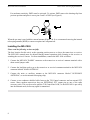
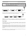
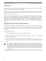
MFJ-1026 Instruction Manual
Deluxe Noise Canceling Signal Enhancer
MFJ-1026
MFJ Deluxe Noise Canceling Signal Enhancer
Instruction Manual
Introduction
To get the best performance from your MFJ-1026, read this manual. It is especially important to heed all
warnings to prevent equipment damage.
The MFJ-1026 is designed to reduce noise or interference, or improve desired signals, before the noise
affects sensitive receiver circuits. Unlike conventional noise blankers, the MFJ-1026 can be effective on
all types of noise, including interference (QRM) from unwanted signals. The MFJ-1026 allows the user
to adjust both phase and amplitude while combining two antenna inputs. The antenna inputs can be
from two external antennas, or an external antenna and the MFJ-1026 internal whip antenna. The signal
output for the receiver is the vector addition or subtraction of signals from two separate antennas. This
allows unwanted noise to be removed or desired signals to be enhanced. The MFJ-1026 is optimized
over the range of 1.8 to 30 MHz.
The phasing method of signal enhancement or null removal has several advantages over conventional
noise blankers. The advantages are:
1. Interference can be much stronger than the signal and be completely removed without affecting the
desired signal.
2. The MFJ-1026 can be effective with all types of interference and on all modes.
3. Signals can be added instead of subtracted with the simple push of a button.
The circuitry in the MFJ-1026 has exceptional phase amplitude flatness, making adjustments easy and
very repeatable. Typical phasing systems provide either limited phase adjustment range, or changes the
signal's level as phase is adjusted. In the MFJ-1026, gain changes less than 3 dB (and typically less than
1 dB) as the phase control is rotated throughout its range.
Effective and proper operation occurs only when the same noise (for nulling noise) or desired signal (for
signal enhancement) is present on both the AUXILIARY (or internal whip antenna) and MAIN antennas.
If the interfering source is not audible on the internal whip antenna, the MFJ-1026 has provisions for
using an external noise antenna (labeled "AUXILIARY ANTENNA" on the rear panel). In most cases, it
will be necessary to use the external AUXILIARY ANTENNA input.
The MFJ-1026 contains interface circuitry necessary for operation with most modern HF transceivers.
Although the MFJ-1026 contains internal T/R (transmit-receive) RF sensing, we STRONGLY
recommend using the external T/R Control line on the rear panel for keying the MFJ-1026.
1
MFJ-1026 Instruction Manual
Deluxe Noise Canceling Signal Enhancer
Failure to use the external control line can result in slow transmitter power rise, or damage to the MFJ1026 components. This is especially true when a transmitter has fast envelope rise time, or has power
"overshoot" on the leading edge of the RF envelope. Some exciters overshoot to as much as 350 watts on
key closure before settling down to rated power.
Theory of Operation
It is commonly perceived that noise interacts with an antenna differently than a "desired" signal. Noise
that propagates over even short distances is an electromagnetic wave. Noise influences the antenna
exactly the same as desired signals. Noise also follows the same rules of propagation as the signals from
our transmitters. Noise does not have to be local in origin, it can also arrive by ionospheric propagation
from distant sources. This effect can allow noise from sources thousands of miles away to accumulate at
the receiving location and "mask" weak signals.
The MFJ-1026 allows you to create a "phased antenna system" out of nearly any pair of antennas. Since
noise and signals all behave the same way before the receiver, this fully adjustable phasing box can be
used to cancel or null unwanted signals, noise, or interference as well as enhance desired signals.
IMPORTANT:
The MFJ-1026 allows almost any combination of antennas to be used as a system, but the MFJ-1026
works best when the main and noise antennas have the same basic patterns when nulling or peaking
distance noise or signals. That means the antennas should be oriented in the same direction and also have
the same basic polarization for best performance.
It is not necessary to use any special length of feedline with the antennas, or for the antennas to be
"resonant" or physically large. Lower Q and smaller antennas often produce the most stable and reliable
performance. Failure to follow this basic guideline will often decrease performance when nulling or
peaking distant signals.
The MFJ-1026 has four primary advantages over typical phased antenna systems:
1. The user can electrically "rotate" the array, even though the antennas remain physically stationary.
2. The user can adjust both direction and wave angle of the null or peak.
3. The user can change from nulling a signal to peaking a signal with the push of a button.
4. Mutual coupling effects can be ignored as phase and level controls are adjusted.
When adding desired signals, the noise and main antennas must both "hear" the desired signal. It is
preferable that both antennas be reasonably close together (within a wavelength) and of similar
polarization. Mixing a vertical antenna with a horizontal will almost always increase fading (contrary to
false rumors that it decreases fading) over an ionospheric path.
2
MFJ-1026 Instruction Manual
Deluxe Noise Canceling Signal Enhancer
When peaking or adding signals, best performance occurs when signals have equal and the best possible
signal-to-noise ratios on both antennas. When adding desired signals, it is preferable to locate both the
MAIN and AUXILIARY antennas as far from local noise sources as possible. Adding desired signals
from a "noisy antenna" into a "quiet antenna's" signal will only make things worse. In the case where one
antenna is significantly noisier than the other, use the quiet antenna for the signal and cancel any noise
with the "noisy antenna".
If the desired application is the removal of distant interference, close spacing is desirable. Close
spacing produces a wider and more stable null. Spacings of one half wavelength or less are most
desirable when nulling distant interference or peaking distant signals.
If the primary problem is removal of local noise, it is preferable the noise (AUXILIARY) antenna
"hear" the noise much louder than it hears desired signals. The noise antenna should be located as close
to the noise source as possible, so the noise antenna picks up the least amount of desired signal and
largest amount of noise possible. In this case the polarization is unimportant, and the spacing between
antennas can be any convenient distance.
Circuit Description
The MFJ-1026 contains a noise amplifier, bridge-type phasing circuit, active combiner, and transmitter
change over relay circuit. The noise pre-amplifier consists of Q9 and Q10. Two jumpers, JMP1 and
JMP2 (see Figure 1), are provided to allow the preamplifier to be used with the external AUXILIARY
ANTENNA connection.
When both JMP1 and JMP2 are "off" or not active, the front panel pre-amplifier switch selects either the
internal whip antenna (PRE-AMP ON position of SW4) or the external AUXILIARY ANTENNA (PREAMP OFF position).
The MFJ-1026 contains internal high-pass filters that begin to roll off on the 160 meter band. These
filters can be bypassed if AM broadcast band interference is not a problem., but the phasing control will
have limited range below 1.5 MHz. With suitable modification the MFJ-1026 will cover from 100 kHz
to 1.6 MHz, or any other 16:1 frequency range between 100 kHz and 35 MHz.
When JMP1 is "on" or active, the internal whip is not used and maximum external amplifier gain is
selected. When only JMP2 is "on" or activated, external AUXILIARY ANTENNA gain is moderate. In
these cases, the PRE-AMP switch either inserts or bypasses the internal amplifier consisting of Q9 and
Q10.
Q8 always drives the bridge-type phasing control.
The PHASE control, R16, allows signals from the AUXILIARY antenna (or internal whip) to be rotated
in phase nearly 180 degrees (φ >145 degrees) over the entire 1.8 to 30 MHz spectrum. PHASE switch
(SW3) allows the selection of either zero (NORMAL) or 180 degrees (INVERT) of additional phase by
selecting the signal from Q7's source or drain. The total phase shift range is the sum of the PHASE
control delay and the delay selected by the PHASE switch.
3
MFJ-1026 Instruction Manual
Deluxe Noise Canceling Signal Enhancer
Q5 and 6 form the active combiner, and Q4 is a line driver supplying output to the receiver.
Q1, Q2 and Q3 are part of RF sensing circuitry. They are included to automatically bypass the MFJ-1026
during transmissions, although we HIGHLY recommend using the rear panel T/R CONTROL line input
whenever possible.
Figure 1
Rear Panel Connections
The MFJ-1026 has a variety of connections on the rear panel. From left to right the connections are:
GND: This connection is used to connect the MFJ-1026 to the station ground buss. Always use a short
ground wire when making this connection. Always try to use solid copper wire (not braided wire) when
making a ground connection. Woven or braided wire has higher RF resistance than solid conductors.
MAIN ANTENNA: This SO-239 provides a direct connection to the RADIO connector whenever
power is removed, if the external T/R CONTROL jack is grounded, or if transmitter power is applied.
This connector should connect to the input of the station's power amplifier or to the rest of the station
accessories, such as wattmeters or antenna tuners.
4
MFJ-1026 Instruction Manual
Deluxe Noise Canceling Signal Enhancer
RADIO: This SO-239 has a direct connection to the MAIN ANTENNA connector when power is
removed, if the external T/R CONTROL jack is grounded, or transmitter power is applied. This
connector should always be connected to the receiver's input connector or to the transceiver's "antenna"
connector.
T/R CONTROL: We STRONGLY recommend using this phono connector to switch the MFJ-1026 to
the transmit (or bypass) mode. The MFJ-1026 switches out-of-circuit whenever this line is pulled low
(below one volt). Never apply negative voltages, or voltages over 15 volts positive, to this jack.
WARNING:
We strongly recommend using this connection to switch the MFJ-1026 into the
transmit mode!! Many radios have sharp transmitter rise times or power pulses
that, at times, cause damage to the MFJ-1026.
AUXILIARY ANTENNA: This SO-239 and the phono jack to its immediate right are inputs for the
auxiliary receive or noise antenna system.
POWER: This 2.1mm coaxial power connector requires a nominal supply voltage of twelve volts at
approximately 150 mA. The center pin is positive.
CAUTION: Do not reverse the power connections or damage will result. Remember, the center pin is
positive, and the outer shell is negative.
Front Panel Controls
The MFJ-1026 has several user controls on the front panel. From left to right, the front panel controls
are:
POWER ON/OFF: This switch turns the main power off and on. In the OFF (out) position, the MFJ1026 is bypassed. The RADIO and MAIN ANTENNA connectors have a direct connection between
each other whenever power is removed or this switch is turned off.
5
MFJ-1026 Instruction Manual
Deluxe Noise Canceling Signal Enhancer
T/R DELAY: This control adjusts the recovery time of the internal bypass relay. Never set this control
for QSK CW operation, always make sure the relay stays closed (you shouldn't be able to hear it click)
during a string of dots.
PRE-AMP ON/OFF: This switch serves two functions:
When both JMP1 and JMP2 are "off" or not active (Figure 2), the front panel preamplifier switch
selects either the internal whip antenna (PRE-AMP ON position) or the external AUXILIARY
ANTENNA (PRE-AMP OFF position).
When JMP1 is "on" or active (Figure 3), the internal whip is not used and maximum external
amplifier gain is selected. When only JMP2 is "on" or activated (Figure 4), external
AUXILIARY ANTENNA gain is moderate. In both of these cases, the PRE-AMP switch either
inserts (ON) or bypasses (OFF) the internal pre-amplifier (consisting of Q9 and Q10).
AUXILIARY ANTENNA GAIN: This control adjusts signal levels from the AUXILIARY antenna
connector. This control is marked from 0 to 10, with 10 having the most gain.
FREQ HIGH/LOW: This switch selects phase components for LOW frequencies (frequencies lower
than somewhere around 7-12 MHz) OUT, or HIGH frequencies (somewhere above the range of 7-12
MHz) IN. In the range of 7-12 MHz, either setting often works.
PHASE: This control is marked from 0-10, and adjusts AUXILIARY signal phase delay over a wide
range. Phase is advanced as the control is rotated clockwise (higher numbers).
PHASE NORMAL/INVERT: This switch selects either normal (IN) or invert (OUT), adding or
removing 180° of additional phase delay.
MAIN ANTENNA GAIN: This control is marked from 0-10, gain increases as the control is advanced
to ten. This control adjusts signal levels from the MAIN ANTENNA connector.
Jumper Settings
Internal Noise Antenna
JMP1 Not Installed
JMP2 Pins 1 and 2 are connected
JMP1
JMP2
The PRE-AMP switch will select either the internal WHIP (ON
position) or the AUXILIARY ANTENNA (OFF position) with
this setup.
Auxiliary Antenna
Maximum Sensitivity
Moderate Sensitivity
Installed
Not Installed
Not Installed
Pins 2 and 3 are connected
JMP1 is a 2-pin header. (Factory default: shorting clip not installed)
JMP2 is a 3-pin header with the pin numbers labeled on the PC Board. (Factory default: pins 1 and 2 are connected.)
6
MFJ-1026 Instruction Manual
Deluxe Noise Canceling Signal Enhancer
Note: MFJ supplies one shorting clip with the MFJ-1026. This shorting clip is the only one needed for
all configurations.
When using the internal noise antenna:
If JMP1 is installed, sensitivity of the internal whip antenna will decrease greatly even if the external
noise antenna is disconnected. Neither JMP1 or JMP2 should be activated when the internal WHIP
antenna is used. The PRE-AMP switch will select either the internal whip (ON position) or
AUXILIARY ANTENNA (OFF position) as long as JMP1 and JMP2 are not activated. The
following diagram (Figure 2) is the factory default setting (JMP1 and JMP2 not activated).
When using an external AUXILIARY ANTENNA:
For maximum sensitivity, internal jumper JMP1 must be activated when an external noise antenna is
used. Remove the shorting clip from JMP2 and place it on the JMP1 header as shown in Figure 3.
7
MFJ-1026 Instruction Manual
Deluxe Noise Canceling Signal Enhancer
For moderate sensitivity, JMP2 must be activated. To activate JMP2 remove the shorting clip from
previous position and place it across pins 2 and 3 of JMP2 (see Figure 4).
When the pre-amp is used with the external antenna (Figure 3 & 4) we recommend removing the internal
telescoping antenna (WHIP) to ensure reception isn't compromised.
Installing the MFJ-1026
Please read the following section carefully.
The best location for this unit is at the operating position next to or above the transceiver or receiver.
The MFJ-1026 controls must be adjusted during normal operation while listening to the receiver or
watching the receiver's S meter. For most installations, connect the MFJ-1026 as follows:
1. Connect the MFJ-1026 "RADIO" connector to the transceiver or receiver's antenna terminal with a
short coaxial jumper cable.
2. Connect the lead that used to go to the transceiver or receiver's antenna terminal to the MFJ-1026
connector labeled "MAIN ANTENNA".
3. Connect the noise or auxiliary antenna to the MFJ-1026 connector labeled "AUXILIARY
ANTENNA", or use the internal telescoping whip.
4. Connect a two-conductor shielded cable between the T/R Control connector and an external PTT
source. Many modern transceivers have an EXTERNAL PTT output pin on one of the radio
accessory ports. This can be used to pull the T/R Control line LOW, so the MFJ-1026 is put safely
into the transmit mode, before any signal is transmitted.
8
MFJ-1026 Instruction Manual
WARNING:
Deluxe Noise Canceling Signal Enhancer
If an antenna tuner is used, always install the MFJ-1026 between the transceiver
and the tuner. NEVER install the MFJ-1026 between the antenna tuner and
antenna. Never use the MFJ-1026 in conjunction with any internal antenna tuner,
unless the SWR without the tuner is less than 2:1.
When using an amplifier install the MFJ-1026 between the transceiver and the amplifier input. NEVER
install the MFJ-1026 on the output of either an amplifier or antenna tuner!
NEVER install the MFJ-1026 after an antenna tuner or an amplifier, due to the RF power and voltage
handling limits of the unit. The RF power handling limit of the MFJ-1026 is approximately 100 watts.
Power Supply
This unit requires 10 to 15 volts dc from a negative ground supply. It consumes less than 150 mA
current. The power jack is a 2.1 mm coaxial power receptacle. The outer connection is grounded and the
center pin is the positive terminal.
While we have made every effort to decouple this line for unwanted noise or RF, it is still possible for
unwanted signals to pass from the power or relay control lines to the receiving system. We recommend
testing for unwanted noise ingress by disconnecting all antennas from the unit, and listening to the noise.
You should hear only a smooth low level hiss with the unit turned on and both gain controls at
maximum.
MFJ recommends a 120 Vac to 12 Vdc (nominal voltage) adapter, model number MFJ-1312B, to power
this unit. This power supply has good RF noise immunity.
9
MFJ-1026 Instruction Manual
Deluxe Noise Canceling Signal Enhancer
Noise Antenna
Please be sure to read the section titled "Theory of Operation" Page 2 of this manual. It contains many
helpful suggestions on antenna selection and installation.
The noise antenna can be a special antenna, or simply a spare antenna not in use at the moment. When
nulling local noise, the best antenna would be one located close to the noise source that "hears" the noise
much better than any desired signals.
LAMP1 is a 50 mA 12 volt dial lamp used to protect the AUXILIARY ANTENNA input from excessive
voltage. Excessive voltage from the transmitter can, under extreme conditions, burn out LAMP1.
Illumination or failure of LAMP1 (located near the AUXILIARY antenna jack) indicates excessive RF
voltages have appeared at the AUXILIARY ANTENNA connector. If LAMP1 illuminates or burns out,
discontinue using that particular AUXILIARY antenna or relocate it further from the transmitting
antenna.
Use with Beverage or Other Low Noise Antennas
The MFJ-1026 can be used to enhance reception on 160 and 80 meters, even if the station already
employs low noise directional receiving arrays. If the receiving antennas connect to the receiver through
a special receiving antenna input connection (a receive antenna jack), the MFJ-1026 should be inserted
in that lead.
A suggested method follows:
1. Connect the MFJ-1026 RADIO connector to the receiver's input line.
2. Connect the MFJ-1026 AUXILIARY ANTENNA connector to the noise, Beverage , or other similar
low noise receiving antenna.
3. Connect the MFJ-1026 MAIN ANTENNA connector to another Beverage or another low noise
receiving array (in some cases even the transmitting antenna can be used to augment the Beverage's
signals) .
Note: The AUXILIARY ANTENNA input has different gain distribution than the MAIN ANTENNA
input. The MAIN ANTENNA input has less internal noise, but also has less available gain than
the AUXILIARY ANTENNA input. NEVER swap these connection if transmitter RF is applied
to the MFJ-1026. In some cases (where the transmitter's RF is not applied through the MFJ1026), weak signal performance may be improved by swapping MAIN and AUXILIARY
antenna inputs.
10
MFJ-1026 Instruction Manual
WARNING:
Deluxe Noise Canceling Signal Enhancer
Transmitter output applied to the RADIO connector appears only on the MAIN
antenna connector. If the transmitter RF is routed through the MFJ-1026 (in other
words, if the MFJ-1026 is connected to the normal antenna output port of your
transceiver), connections to the MAIN and AUXILIARY antennas can not be
reversed.
In order to null or peak a signal, both the MAIN antenna and the AUXILIARY antenna must "hear" the
same signal. If the same noise or signal is not present on both antennas, noise or signals can not be
properly nulled or peaked. This requirement may require installation of a special antenna near the noise
source to null unwanted local noise signals, or require installing a separate low noise receiving antenna
to enhance desired distant signals.
Grounding Considerations
Connect the MFJ-1026 to the station ground buss with a short ground connection. Always use a good
station ground connection to reduce the risk of lightning damage to station equipment, improve
performance, and to improve operator safety.
Adequate lightning protection can be obtained by burying coaxial feedlines directly in the ground for 20
feet (or more) before the feedline enters the building. In addition, the feedline's shield should be
grounded to the station ground at the point where the feedline enters the building. Failure to follow
these precautions will increase the risk of lightning damage to equipment and reduce safety.
The station's ground should consist of at least one copper ground rod driven into the earth a minimum of
6 feet. Multiple ground rods and buried wires are superior to a single rod for lightning and RF
protection.
Never use woven conductors or flexible braiding for ground connections unless absolutely necessary.
Braiding has high resistance to RF and lightning. Copper flashing, wide copper foil, or large gauge nonstranded copper conductors (even if hollow) are the best materials for use in RF and lightning grounding
applications. Never ground a two wire balanced feedline on the antenna side of the balun.
In-line coaxial lightning arrestors offer a minimal improvement in lightning protection. The best method
of protecting station equipment is to disconnect the feedline outside the building during threatening
weather or when the station is not in use.
11
MFJ-1026 Instruction Manual
Deluxe Noise Canceling Signal Enhancer
Operation
This unit requires 10 to 15 volts dc, available from your station supply or an optional MFJ-1312B
power supply.
If you have a general coverage receiver, select a strong steady signal between 1.5 and 30 MHz. The
ideal signal would be ground wave, although the time and frequency standards on 5 , 7.335, and 10 MHz
are good alternatives. It is important to select a signal with little or no fading for initial practice.
1.
Connect the MFJ-1026 to your station and a suitable power source. See the Installation instructions
on page 8.
2.
From left to right:
a. Turn the T/R DELAY control fully clockwise.
b. Press and release the POWER switch to place it in the OFF (out) position.
c. Turn the AUXILIARY ANTENNA GAIN control fully counter-clockwise.
d. Release the frequency range for operation below 7-12 MHz, or press and lock it for operation
above 7-12 MHz. In the range of 7-12 MHz, either setting may work.
e. Adjust the MAIN ANTENNA GAIN control fully clockwise.
3.
Tune in a strong steady signal.
4.
Turn the MFJ-1026 power switch on. The red LED should light and you should hear the internal
relay click.
5.
You should still hear the same signal. Look at the receiver's S meter and remember the signal
strength. Adjust the MAIN ANTENNA GAIN control counter-clockwise, signal strength should
decrease. Turn the control fully counter-clockwise.
6.
Advance the AUXILIARY ANTENNA GAIN control clockwise. You should hear signals from the
AUXILIARY antenna.
7.
Adjust the AUXILIARY ANTENNA GAIN until the signal is just exactly the same as the level
observed on the MAIN antenna, or as high as possible.
8.
Advance the MAIN ANTENNA GAIN until you just see the S meter change.
9.
Adjust the PHASE control for minimum signal. If the signal strength increases or won't null,
change the position of the PHASE switch.
10. Go back and forth between the PHASE and the GAIN control that isn't totally against the stop while
watching for a null. Adjust only one GAIN control, do not adjust the control that is fully advanced.
This step may take some practice until you get a "feel" for how the controls work..
11. Practice nulling several steady signals until you are comfortable with the action of the controls.
12
MFJ-1026 Instruction Manual
Deluxe Noise Canceling Signal Enhancer
12. Try peaking a signal. The strongest peak will usually be very near the setting of the PHASE control
that produces the deepest null for the same signal, but the PHASE switch will be in the opposite
position from the null position. When peaking a signal, never adjust gain setting. Adjust the
PHASE control and PHASE switch only.
13. After gaining experience on strong steady signals, practice nulling background noise or unwanted
signals.
Remember, you can only null a signal or noise if it is present on both the noise and main antennas.
Fading may make it difficult to obtaining a complete null on skywave signals. The most consistent null
will occur if the antennas are moderately close together (between 1/2 and 1/8 wl apart), oriented in the
same direction, and sharing the same polarization.
This device contains a circuit that automatically disables it when transmitting. The T/R DELAY control
will adjust the recovery time of this circuit. If the unit is off, or if the T/R CONTROL line is grounded,
the MAIN ANTENNA port is directly connected to the RADIO port.
WARNING:
When transmitting with high power and using external antennas located close
together, excessive RF may illuminate or burn out the fuse lamp at the AUXILIARY
ANTENNA connector. This bulb is rated at 50 mA of current. Never replace this
bulb with higher current bulbs. If fuse lamp burn out is a problem, the antennas
must be moved further apart or an external relay must be used to disconnect the
auxiliary antenna while transmitting.
Other Applications
Since this unit is really an adjustable phasing network that combines two antennas to give various
directional patterns, it can improve receiving signal levels even in the absence of strong noise. For
example:
1. Two parallel Beverage antennas spaced an eighth to quarter wave apart with an eighth to quarter
wave stagger in the desired direction can be combined to improve front to back, steer nulls, or add
desired signals.
2. Two verticals or dipoles can be combined producing a steerable array capable of peaking or nulling
signals.
3. A Beverage and a quiet main transmitting antenna can be combined to enhance weak signals.
Many other combinations are possible. The best system is found by experimentation.
13
MFJ-1026 Instruction Manual
Deluxe Noise Canceling Signal Enhancer
Technical Assistance
If you have any problem with this unit first check the appropriate section of this manual. If the manual
does not reference your problem or your problem is not solved by reading the manual, you may call MFJ
Technical Service at 601-323-0549 or the MFJ Factory at 601-323-5869. You will be best helped if you
have your unit, manual and all information on your station handy so you can answer any questions the
technicians may ask.
You can also send questions by mail to MFJ Enterprises, Inc., 300 Industrial Park Road, Starkville, MS
39759; by Facsimile (FAX) to 601-323-6551; or by email to:
[email protected]
Send a complete description of your problem, an explanation of exactly how you are using your unit, and
a complete description of your station.
14
MFJ-1026 Instruction Manual
Deluxe Noise Canceling Signal Enhancer
Schematic
15
MFJ-1026 Instruction Manual
Deluxe Noise Canceling Signal Enhancer
Settings Log
use this log to record settings
Freq
16
Direction
AUXILIARY
Antenna
Main
Antenna
AUXILIARY
gain
Phase
Rev
MAIN
gain