1
ALESIS
1622 Mixer
Reference Manual
TABLE OF CONTENTS
INTRODUCTION.................................................................................................................... 2
WHAT IS A MIXING CONSOLE?............................................................................... 2
FEATURES................................................................................................................ 2
SECTION 1
DESCRIPTION OF CONTROLS ................................................................................ 3
TOP PANEL .................................................................................................. 3
INPUT TRIM ..................................................................................... 3
EQ .................................................................................................... 3
SENDS ............................................................................................. 3
PRE-FADER SENDS............................................................ 3
POST-FADER SENDS ......................................................... 4
MASTER ASSIGN SWITCH ............................................................. 5
SUB MASTER ASSIGN SWITCH ..................................................... 5
MUTE SWITCH ................................................................................ 6
SOLO SWITCH................................................................................. 6
PAN POT.......................................................................................... 6
CHANNEL FADER............................................................................ 6
SEND MASTERS.............................................................................. 6
TAPE/MONITOR SWITCH................................................................ 6
MONITOR VOLUME ......................................................................... 6
EFFECTS RETURNS ....................................................................... 6
SUB MASTER FADERS ................................................................... 7
SUB MASTER TO MASTER ASSIGN SWITCH................................ 7
MASTER FADERS............................................................................ 7
BACK PANEL................................................................................................ 7
MIC/LINE INPUTS ............................................................................ 7
MICROPHONE INPUTS ................................................................... 7
DIRECT OUTPUTS........................................................................... 7
CHANNEL INSERTS......................................................................... 8
SENDS ............................................................................................. 8
RETURNS ........................................................................................ 8
HEADPHONE ................................................................................... 8
SUB OUT.......................................................................................... 8
SUB INSERT .................................................................................... 8
MAIN OUT ........................................................................................ 8
MAIN OUT LEVEL SELECTOR ........................................................ 8
MAIN INSERT................................................................................... 8
MONITOR OUT ................................................................................ 8
POWER SUPPLY CONNECTOR...................................................... 8
ON/OFF SWITCH ............................................................................. 9
SIGNAL FLOW IN THE 1622 ..................................................................................... 9
SECTION 2
SETTING UP THE 1622 ............................................................................................ 12
CONNECTIONS TO THE MIXER .................................................................. 12
INTERFACING TO A MULTITRACK TAPE RECORDER:
4 TRACK THROUGH 8 TRACK RECORDING ..................... 12
INTERFACING TO THE MULTITRACK TAPE RECORDER VIA A
PATCHBAY ...................................................................................... 13
INTERFACING THE 1622 MIXER TO THE MIXDOWN DECK.......... 14
INTERFACING THE 1622 MIXER TO THE CONTROL ROOM
MONITOR SPEAKERS..................................................................... 15
INTERFACING THE 1622 MIXER TO A HEADPHONE AMP ............ 15
INTERFACING THE SENDS AND RETURNS OF THE 1622 MIXER TO
EFFECTS ......................................................................................... 15
INSERT INTERFACING.................................................................... 15
HOW TO ADJUST LEVELS .......................................................................... 16
SECTION 3
APPLICATIONS ........................................................................................................ 18
MULTITRACK RECORDING ......................................................................... 18
INTRODUCTION TO MULTITRACK RECORDING........................... 18
RECORDING ....................................................................... 18
MONITORING ...................................................................... 19
MULTITRACK MIX................................................... 19
MONITOR SPEAKER (CONTROL ROOM) MIX....... 19
CUE MIX.................................................................. 19
MIXDOWN ........................................................................... 19
THE 1622 MIXER AND A 4 OR 8 TRACK TAPE DECK................................. 19
USING THE 1622 MIXER TO RECORD
A SINGLE SOURCE TO 1 TRACK ....................................... 20
TWO OR MORE SOURCES TO 1 TRACK........................... 20
2 OR MORE SOURCES TO 2 TRACKS............................... 20
RECORDING TIPS ........................................................................... 21
HOW TO PLAYBACK FROM MULTITRACK..................................... 21
HOW TO SET UP A CUE ................................................................. 22
MIXDOWN........................................................................................ 22
HOW TO CREATE A DEPENDABLE MIX........................................ 23
HOW TO GROUP SEVERAL CHANNELS TOGETHER
WHEN MIXING ................................................................................. 25
HOW TO PLAYBACK A MIX FROM THE MIXDOWN TAPE DECK .. 26
PLAYBACK TIPS.................................................................. 26
SOUND REINFORCEMENT APPLICATIONS IN MONO .................. 27
USING THE SUB MASTERS ............................................................ 28
LINE INPUTS USED AS ADDITIONAL MIC INPUTS ........................ 29
USING THE SUB MASTERS FOR SEPARATE OUTPUTS .............. 29
STAGE MONITOR MIX FROM THE PRE-FADER SENDS ............... 30
DEDICATED MIDI KEYBOARD MIXER......................................................... 30
SECTION 4
TROUBLESHOOTING .............................................................................................. 32
NO SOUND ................................................................................................... 32
NO SOUND WHEN CHANNEL IS SOLOED ..................................... 32
NO SOUND WHEN MONITOR LEVEL TURNED UP........................ 32
OVERLOAD PROBLEMS .............................................................................. 32
DISTORTION HEARD WHEN INPUT CHANNEL IS SOLOED.......... 32
DISTORTION IS BEING RECORDED ONTO TAPE, BUT DISTORTION
NOT HEARD WHEN INPUT CHANNEL IS SOLOED........................ 33
DISTORTION AT MIXDOWN MACHINE OR SOUND SYSTEM ....... 33
DISTORTION ON THE RETURNS.................................................... 33
SECTION 5
GROUNDING............................................................................................................. 33
SECTION 6
SPECIFICATIONS ................................................................................................................. 35
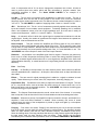
GLOSSARY ........................................................................................................................... 36
APPENDIX ............................................................................................................................. 42
INDEX .................................................................................................................................... 44
BLOCK DIAGRAM................................................................................45
Alesis 1622
Monolithic/Integrated Surface™ Audio Console
USER'S MANUAL
Alesis 1622
Monolithic/Integrated Surface™ Audio Console
INTRODUCTION
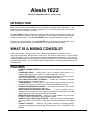
The Alesis 1622 Monolithic/Integrated Surface™ Audio Console is a 16 channel, two buss
audio mixing console which features the new Integrated Monolithic Surface™
technology. This
technology makes available a number of features at low cost which previously could only be
found in much more expensive consoles .
The 1622 MIXER provides excellent sonic qualities, with extremely low noise and crosstalk, flat
wideband frequency response, and the superb sweet sound normally associated with consoles
costing many times more. Thus the 1622 MIXER can be used as an additional "Musical Tool" .
Because of the built-in flexibility of the 1622 MIXER, the unit is at home in any application, be it
recording, sound reinforcement, post-production, or as a dedicated keyboard mixer.
WHAT IS A MIXING CONSOLE?
As the name implies, a mixing console "mixes" audio signals together from various sources
(microphones, keyboards, tape machines, reverbs, etc.). But unlike a simple "mixer", a mixing console
is really the "brain" or center of the entire sound system, regardless of the application, since it not only
mixes the signals together, but also provides routing of these signals to tape recorders, effects devices,
and other audio systems. The console also allows for adjustment of monitoring levels independent of
recording levels.
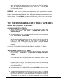
FEATURES
•
•
•
•
•
•
•
•
•
•
16 INPUT CHANNELS WITH EQ - Plenty of inputs for keyboards, microphones, or
effects
6 AUXILIARY SENDS - Sends signal to up to 6 outboard effects devices, or 4
outboard effects devices and 2 mono or 1 stereo headphone cue mixes
8 AUXILIARY RETURNS - Special dedicated inputs designed to blend the returns
of any combination of 8 mono or 4 stereo outboard effects devices
SOLO FUNCTION ON INPUT CHANNELS - Enables any overloads or unwanted
background noise to be easily detected
2 SUB MASTERS - Makes it easy to control several input channels with just one
fader (or two for stereo), or control record levels during multitrack recording
CONTROL ROOM MONITOR SECTION - Sets a level for the control room monitor
speakers that is independent of the main mix
ELECTRONICALLY BALANCED MIC INPUTS - A feature normally found on
consoles that are many times more expensive, this allows for both lower noise and
greater headroom in the most critical stage of the console
MIXDOWN TAPE DECK RETURN - Allows you to hear playback of your mix from
the stereo mixdown tape machine just by flipping a switch
INSERTS ON ALL INPUTS AND OUTPUTS - Allows for patching outboard signal
processing devices such as EQ's, compressors, and effects directly into the signal
path
8 DIRECT OUTPUTS - Allows for the quietest operation by bypassing unused
electronics and sending the channel signal directly to the input of a Multitrack Tape
Machine
2
3
SECTION 1
DESCRIPTION OF CONTROLS
TOP PANEL
INPUT TRIM
The INPUT TRIM is a variable gain control that allows the preamp stage of the mixer to boost
the level of a mic or line level signal being fed into the input. The input section of any mixer is
the most critical due to the high gain required to amplify such a low level signal (such as that of a
microphone) to a usable level. If the gain is set too high, a hot signal from a synthesizer or loud
vocalist will cause the input stage to overload and distort. If the gain is set too low, additional
gain must be added at some other point in the mixer (such as the faders) which could cause
excessive background noise at the output.
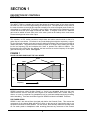
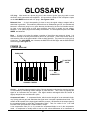
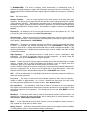
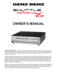
EQ
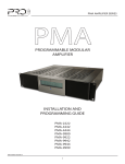
The equalizer, or EQ, section consists of simple bass and treble controls similar to that of a
guitar amp or home stereo. EQ allows for any tonal shaping that might be required by a signal.
For the technically minded, these are known as shelving equalizers and have turnover points at
10KHz and 100Hz. This means that the maximum boost or cut begins from 10KHz (and 100Hz
for the low frequency EQ) and maintains this "shelf" or plateau from 10KHz to 20KHz. The
frequencies below 10KHz are also affected, but less and less so as the frequency of the signal
gets further away from 10KHz. See Figure 1
FIGURE 1
HI AND LO SHELVING EQ OF THE 1622 MIXER
SHELF
100Hz
10KHz
+15dB
+15dB
0 dB
0 dB
-15dB
-15dB
Frequency
SENDS
SENDS (sometimes called "Auxiliary Sends" or "Aux's") are adjustable feeds from the input
channel that are used to send part of the signal to an outboard effect, like a reverb, delay, or
chorus, or to set up a separate cue (headphone) mix for musicians headphones during recording
and overdubbing. There are two different types of SENDS included in the 1622. These are:
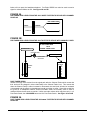
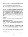
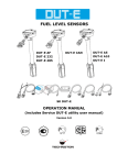
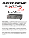
PRE-FADER SENDS
SENDS 1 and 2 are derived from the signal path before the Channel Fader. This means that
movements of the channel fader will have no effect on the amount of signal being sent to any
equipment connected to these SENDS. For this reason, these auxiliary sends are normally used
as cue sends (sends to headphones while recording) because any movement of the channel
4
faders will not upset the headphone balance. Pre-Fader SENDS can also be used to send a
signal to outboard effects as well. See Figure 2A and 2B
FIGURE 2A
PRE-FADER SEND LEVEL FROM THE 1622 MIXER TO EFFECTS DEVICE WITH CHANNEL
FADER UP
PRE-FADER SEND
SIGNAL
INPUT
FADER UP
MASTER
FIGURE 2B
PRE-FADER SEND LEVEL FROM THE 1622 TO EFFECTS DEVICE WITH CHANNEL FADER
B. PRE-FADER SEND
WITH
CHANNEL FADER DOWN
INSTRUMENT/MIC
PRE-FADER SEND
EFFECTS DEVICE
TO HEADPHONES
OR EFFECTS
INPUT
LED METER
+3
CHANNEL
0VU
FADER
-10
-20
-30
-40
-50
-60
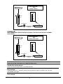
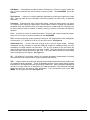
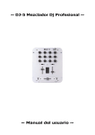
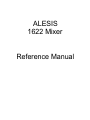
POST-FADER SENDS
SENDS 3 through 6 are derived from the signal path after the Channel Fader which means that
their levels will be changed in direct relationship to the Channel Fader level. This means that
when the Channel Fader is either increased or decreased, the send level will also be increased
or decreased and the effects (or headphones) would get louder or softer. Since this wouldn't be
too great for a headphone balance, these Post-Fader sends are normally used to send to
outboard effects devices such as reverbs. Unlike most other mixers which may have only 1 or 2
Post-Fader Sends, the 1622 MIXER has a total of 4 Post-Fader Sends. See Figure 3A and 3B
FIGURE 3A
POST-FADER SEND LEVEL FROM THE 1622 MIXER TO EFFECTS DEVICE WITH CHANNEL
FADER UP
5
A. POST-FADER SEND
WITH
INSTRUMENT/MIC
CHANNEL FADER UP
INPUT
LED METER
+3
0VU
-10
CHANNEL
-20
FADER
-30
-40
-50
-60
POST-FADER SEND
EFFECTS DEVICE
TO HEADPHONES
OR EFFECTS
FIGURE 3B
POST-FADER SEND LEVEL FROM THE 1622 MIXER TO EFFECTS DEVICE WITH CHANNEL
FADER DOWN
B. POST-FADER SEND
WITH
INSTRUMENT/MIC
CHANNEL FADER DOWN
INPUT
LED METER
+3
0VU
-10
CHANNEL
-20
FADER
-30
-40
-50
-60
POST-FADER SEND
EFFECTS DEVICE
TO HEADPHONES
OR EFFECTS
MASTER ASSIGN SWITCH
Routes the channel signal directly to the MASTER Stereo Buss.
SUB MASTER ASSIGN SWITCH
Routes the channel signal directly to the SUB MASTER.
MUTE SWITCH
Turns the channel off. The MUTE switch does not affect the signal on SENDS1 and 2 but will
mute SENDS 3 through 6.
SOLO SWITCH
6
SOLO disconnects the normal signal feed to the monitor speakers and replaces it with the signal
present at the Channel Fader. When a channel is soloed, the signal will be heard in mono
regardless of the position of the pan pot, and without any effects via the Sends and Returns.
Soloing enables the engineer to hear exactly what is being recorded by eliminating the masking
effects caused by the presence of other signals. When soloed, distortion caused by overloading
or other undesired background noises in an input channel can be heard easily.
SOLO switches can be used at any time without interrupting the signals sent to the headphones
or recorded on tape since the soloed signal is only heard through the Monitor Speakers. By
engaging additional SOLO switches, as many signals as desired can be soloed simultaneously.
PAN POT
The PAN POT places the signal of the channel anywhere in the stereo field between the left and
right channels of the MASTER or SUB MASTERS (or both) depending upon which is assigned.
If the PAN is set all the way to the left, the signal will appear only on the left SUB MASTER or
MASTER fader. If the PAN is set all the way to the right, the signal will appear only on the right
SUB MASTER or MASTER fader.
CHANNEL FADER
The CHANNEL FADER determines the overall volume level of the channel. It is normally best
to keep this FADER at about the 3/4 level for the most headroom and least background noise.
SEND MASTERS 1 through 6
This is the overall master for the corresponding SEND of each channel. Therefore, if the level of
SEND 1 was too hot and causing distortion, the overall level could be trimmed by adjusting
SEND MASTER 1, which would lower the signal without having to individually adjust each
channel SEND.
TAPE/MONITOR SWITCH
When the 1622 MIXER is used for recording, this switch will determine what you hear in the
control room monitor speakers. When in the TAPE position, the signal from the Mixdown Tape
Deck will be heard and can be adjusted from the MONITOR VOLUME pot. When in the
MONITOR position, the signal from the console, as adjusted by the MASTER Faders and
MONITOR VOLUME pot, will be heard.
MONITOR DEFEAT SWITCH
This switch will mute the signal going to the control room monitor speakers in the event that it is
necessary to monitor with headphones via the headphone jack. This switch has no effect on the
signals appearing at the MASTER Faders.
MONITOR VOLUME
The MONITOR VOLUME Control adjusts the volume level of the control room monitor speakers
only. When the 1622 is used as a recording console, it is necessary to be able to control the
level of the control room monitor speakers and the MASTER Fader output levels independently.
Without the separate MONITOR VOLUME control, both the control room speakers and the
mixdown tape level would be controlled by the MASTER Faders, which would cause either a
distorted or noisy signal going to tape when the speaker levels were correct, or too loud or soft
speaker levels when the tape machine levels were correct.
EFFECTS RETURNS
The EFFECTS RETURNS are additional inputs (besides the 16 Channel Inputs) especially for
outboard effects such as reverbs, delays, chorus, etc. These inputs eliminate the need to
connect effects to channel inputs and, therefore, keep the input channels available for additional
microphones, synthesizers, etc.
There are 8 EFFECTS RETURNS on the 1622 MIXER . RETURNS 1 through 4 each have a
PAN control which allows the the return signal to be placed anywhere in the stereo spectrum
from left to right. RETURNS 5 and 7 are permanently assigned to the Left MASTER Buss, and
RETURNS 6 and 8 are permanently assigned to the Right MASTER Buss.
SUB MASTER FADERS
7
The SUB MASTER Faders can serve several different functions, depending upon the
application. In sound reinforcement or in recording during mixdown, the SUB MASTER Faders
will act as a group master for a number of input channels. For instance, if Input Channels 1
through 8 contained drum mics, and you wanted to control the overall level of the drums with just
one fader, this could be achieved by assigning input channels 1 through 8 to the SUB MASTER
ASSIGN, and then panning each channel either hard left or hard right (for mono). The SUB
MASTERS could also be assigned in stereo by panning the input channels to any point in the
stereo spectrum, in which case the composite signal will appear on both the right and left SUB
MASTER faders. See Section 3.
During recording, the SUB MASTERS can be used to mix several signals together onto a single
track (or two tracks for stereo) by assigning those input channels to the SUB MASTERS and
connecting the SUB OUT jack to the track that you wish to record on. See Section 3.
SUB MASTER TO MASTER ASSIGN SWITCH
This switch routes the signal on the SUB MASTERS to the MASTER Faders.
MASTER FADERS
The Left and Right MASTER Faders control the main output of the console to either the mixdown
deck (in recording) or the sound system (in sound reinforcement).
MAIN STEREO METERS
The main STEREO METERS, each consisting of 7 green, 4 yellow, and 4 red LEDs, show the
relative output levels of the MASTER Faders. The METERS will also show the level of any input
channel that has its SOLO engaged.
SOLO/POWER LEDS
The SOLO LED lights whenever a solo is switched on. The POWER LED lights whenever AC
power is connected to the unit.
BACK PANEL
MIC/LINE INPUTS
Channels 1 through 16 can be accessed via a 1/4" phone jack. Normally, this would be used for
line level signals such as synthesizers or tape machines but it is also possible to feed a
microphone signal into this jack. In 4 or 8 track recording applications, channels 9 through 16
would normally be used for tape returns of tracks 1 through 8, while channels 1 through 8 would
be used for mic or instrument inputs.
MICROPHONE INPUTS
Channels 1 through 8 contain an XLR jack which provides an electronically balanced input
ideally suited for a microphone. This input is overridden should a plug be inserted in the
corresponding Input phone jack (XLR #1 is defeated if a phone plug is inserted in phone jack
#1).
DIRECT OUTPUTS
Channels 1 through 8 contain a DIRECT OUTPUT jack. Each channel routes its own input
signal, after it has been amplified and EQ'd, to the Direct Output jack. This is generally used to
feed a single track of a Multitrack Tape Deck. Because the Direct Output is the path with the
least amount of circuitry and therefore the lowest possible background noise, it is most desirable
to use when recording the signal of only a single channel.
CHANNEL INSERTS
Channels 1 through 16 each contain a stereo jack called an INSERT. This consists of an insert
send (the tip of a stereo phone plug) and insert return (the ring of a stereo phone plug) and is
used to insert an outboard effects device, such as a compressor, EQ, or chorus, directly into the
8
signal path of only that channel. A special cable consisting of a single stereo 1/4" jack on one
end and two mono 1/4" jacks on the other is required. See Section 2 - INSERT INTERFACING
SENDS
These jacks feed the signal from SEND MASTER 1 through 6 to an outboard effects device or
headphone amplifier. SENDS 1 and 2 are derived Pre-Fader while SENDS 3 through 6 are
derived Post-Fader.
RETURNS
The RETURN jacks are especially dedicated to the signals returning from any outboard effects
devices back into the 1622 MIXER. RETURNS 1 through 4 are pannable between the Left and
Right MASTER buss. RETURNS 5 and 7 are permanently assigned to the Left MASTER.
RETURNS 6 and 8 are permanently assigned to the Right MASTER.
HEADPHONE
Controlled from the MONITOR VOLUME pot, the HEADPHONE jack provides substantial level
to drive most headphones. It is not affected by the MONITOR DEFEAT switch.
SUB OUT
The outputs of the SUB MASTERS are available for connection to the inputs of a tape machine.
In certain applications, such as video post production, the SUB OUTS may also have a different
mix, such as a mix containing music and effects but minus the dialog, from the one available at
the MAIN OUTPUTS.
SUB INSERT
A ring-tip-sleeve jack that allows insertion of an outboard effects device, such as a compressor
like the Alesis MICRO LIMITER or reverb like a MICROVERB II, into the signal path of the SUB
MASTER.
MAIN OUT
The outputs of the MAIN OUT are available for connection to the inputs of a Mixdown Tape
Machine, sound system, or amplifier.
MAIN OUT LEVEL SELECTOR
This switch selects the proper level for use with either professional or semi-professional
equipment. Select the +4dBV position (switch pressed in) for most sound systems and
professional tape machines. Select the -10dBV position (switch out) for connection to guitar
amplifiers or cassette decks. Generally speaking, use the -10dBV setting if you are connecting
to a device that uses RCA jacks. Use the +4dBV setting for a device that uses XLR inputs. For
a device that uses 1/4" phone jacks, try both settings and choose the one with the lowest
background noise (hiss and hum).
MAIN INSERT
Allows for the insertion of an outboard effects device, such as the Alesis MICRO LIMITER or
the Alesis QUADRAVERB, into the signal path of the MAIN Outputs.
MONITOR OUT
The outputs of the MONITOR OUT are available for connection to the inputs of the amplifier for
the control room monitor speakers. The level is controlled by the MONITOR VOLUME pot.
TAPE INPUT
For connection of the output of a mixdown deck during recording. This will allow you to hear the
playback of your mix without repatching.
POWER SUPPLY CONNECTOR
Connection for Alesis 1622 power supply.
9
ON/OFF SWITCH
Turns power on or off to the 1622. This should always be the first device turned on in the system
and the last device turned off.
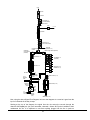
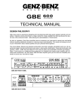
SIGNAL FLOW IN THE 1622
To help you better understand the way that the 1622 operates, the following is a Signal Flow
Diagram of the complete signal path of the 1622.
FIGURE 4
1622 SIGNAL FLOW
10
Input
Input Trim
EQ Section
Aux Sends 1 - 2
(Pre-Fader Sends)
Channel Insert
Mute
Solo
to Solo Buss
Input Fader
Aux Sends 3 - 6
(Post - Fader Sends)
Direct Out
(Channels 1 - 8)
Left/Right Pan
Control
Submaster
Assign Switch
(Channel)
Master Assign Switch (Channel)
Sub Inserts 1 - 2
Aux Returns 1 - 4
(Pannable)
Sub Faders 1 - 2
Aux Returns 5 - 8
(Hardwired L - R)
Sub Outs 1 -2
From
Mixdown
Deck
Submaster to
Master Assign
Switch
Master Inserts (L - R)
Tape/Line
Monitor
Switch
Master Faders (L - R)
Control
Room
Monitor
Volume
To
Headphone
Jack
Monitor
Outputs
(L - R)
Master Outs (L - R)
Now, using the above Signal Flow Diagram, let's see what happens to a vocal as it goes from the
input of a channel all the way to tape.
Starting at the top of the diagram, the signal from the mic enters the console through the
channel's XLR Input jack. (As you'll remember, channels 1-8 have XLR jacks in addition to their
unbalanced line ins. It is important to note that anything plugged into the line in jacks on
11
channels 1-8 will defeat the XLR jack for that channel). The signal is then boosted by the Input
Trim to a level that the board can deal with easily. Now, you can adjust the tone of the singer's
voice with the EQ Section, perhaps boosting the presence range a bit, or rolling off the low end
to compensate for close miking. After you've done this, you can grab the signal via Aux Sends
1 - 2 and send it out of the first two Send jacks. Since these are Pre-Fader sends, the level of the
signal going out of these jacks will not be affected when the input fader's level is adjusted.
Because of this, they're perfect for setting up a cue mix, allowing the singer to hear the optimum
blend of vocals, instruments, and effects.
Next comes the Channel Insert. This is a combination Send/Return accessed via the stereo
Insert jack. Since the jack contains both the send and return, a special cable must be used, with
the tip being used as the Send and the ring as the Return. Using the Channel Insert, we can
smooth out the level of the vocal with a MICRO LIMITER before it goes to tape.
After the signal passes through the Input Fader, it can be sent out the other Send jacks via Aux
Sends 3 - 6. Since these sends are taken from a point after the Input Fader, the level of the
signal going out of them will be affected when you adjust the Input Fader. These sends are more
suited to outboard effects like reverb, flanging, or delay. Later, when we mix down, we'll use
these sends to set up a cool blend of QUADRAVERB and MICROVERB II to accentuate the
performance.
Channels 1-8 each feature a Direct Out, which is generally used to feed a multitrack tape
machine. The signal that is sent out of this jack is taken from the same point as the Post-Fader
Sends. The vocal will then be sent through a Left/Right Pan Control, which determines its
position in the stereo field relative to all of the other instruments and effects. We'll use this to set
the vocal just a little off to the left of dead center in the mix, with the vocal effects panned a little
right to make the vocal sound big and spacious. Then, depending on how the Submaster and
Master Assign Switches are set, the vocal channel's signal is grouped with signal from other
channels and sent to the submaster buss, the master buss, or both.
First off, let's say the Submaster Assign Switch is enabled. Before the vocal and the other
instrument signals get to the faders that will determine their overall level, you have a chance to
send them out of the board, effect them as a group, and return them back into the SubMaster
buss using either of the Sub Inserts. We could use these to run all of the instruments through a
single reverb for overall ambience. These inserts work along the same lines as the Channel
Inserts. The only difference is that an effect inserted at this point will effect all of the channels
that have been assigned to SubMaster 1 or 2 (depending on which insert you are using). Next,
you'll set the overall level of the combined (and effected) signals with Sub Faders 1 - 2, and the
signal will then be sent out of the jacks marked Sub Outs 1-2.
Depending on how you're using the SubMaster busses, you may or may not want the grouped
Sub signals to be routed into the Master buss. You can determine whether or not this will happen
by enabling or disabling the SubMaster to Master Assign Switch.
Backing up a bit, let's say that our vocal channel's Master Assign Switch (just after the Pan
Control) is enabled. These grouped signals will be sent through an insert/fader/output jack
system similar to the one found on the SubMaster, but first they will be mixed with the aux
returns. Aux Returns 1-4 are mono returns pannable to any point in the stereo field. This is
where we'll control the level and panning of the QUADRAVERB/MICROVERB II effects blend on
the vocal during mixdown. You can use one as a mono return, or you can group together two as
a stereo return by panning them hard left and right. Aux Returns 5-8 are hardwired left and right
as shown, providing two more pairs of stereo returns.
Next on the flow chart are the Master Inserts. These work the same as the Sub Inserts, but
since the SubMasters feed into a point before the Master Inserts, any effect that is inserted into
the Master Inserts will also effect the signal coming from the SubMasters (as long as the
SubMaster to Master Assign switch is enabled).
Next are the Master Faders and Master Outs. The Faders set the overall level of the grouped
signals in the Master buss, which are then sent to the Master Out jacks. This is where we'll do the
12
long fade on the whole mix at the end of the tune. This mixed signal, however, is also sent to the
monitoring system. Since the Master Out jacks are generally connected to a stereo mixdown
deck, your monitoring system (amp/speakers, headphones, etc.) has its own set of jacks - the
Monitor Outputs - that are fed from the same source as the Main Outs.
There's also a Headphone Jack that is fed from the same source, and the volume for both of
these outputs is controlled by the Control Room Monitor Volume, which is the big knob up in
the corner of the board.
After you've finished your mix and you want to hear it back through your monitors, instead of
repatching, you can connect the mixdown deck's outputs to the Tape In jacks, flip the Tape/Line
Monitor Switch, and presto! - you're listening to your mix.
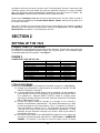
SECTION 2
SETTING UP THE 1622
CONNECTIONS TO THE MIXER
The 1622 Mixer easily interfaces to most other audio equipment. All input and output jacks, with
the exception of the dedicated microphone inputs, are 1/4" phone jacks. The microphone inputs
are standard balanced XLR type jacks. See Figure 5.
FIGURE 5
CONNECTOR TYPES ON THE 1622
INPUT
CONNECTOR
MIC INPUTS
LINE INPUTS
DIRECT OUTPUTS
INSERTS
SENDS
RETURNS
SUB-MASTER OUTPUTS
MAIN STEREO OUTPUTS
CONTROL ROOM MONITOR
TAPE RETURN
HEADPHONE
XLR
1/4" Mono
1/4" Mono
1/4" Stereo
1/4" Mono
1/4" Mono
1/4" Mono
1/4" Mono
1/4" Mono
1/4" Mono
1/4" Stereo
TYPE
BALANCED
UNBALANCED
UNBALANCED
UNBALANCED
UNBALANCED
UNBALANCED
UNBALANCED
UNBALANCED
UNBALANCED
UNBALANCED
UNBALANCED
INTERFACING TO A MULTITRACK TAPE RECORDER: 4 TRACK THROUGH
8 TRACK RECORDING
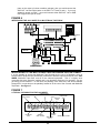
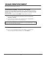
Interfacing the 1622 MIXER to your Multitrack Tape Deck is easy to do. See Figure 6.
1) Connect any microphones or instruments to be recorded into the MIC or LINE
INPUTS of Channels 1 through 8.
2) If only the signal from a single channel is to be recorded, it is also possible to
use the DIRECT OUTPUT of that channel to patch directly into the track that is
to be recorded on. Using the DIRECT OUTPUT results in a slightly quieter
signal being recorded since there are fewer electronic components in the signal
path to add background noise.
3) Connect the Inputs of Channel 9 through 16 (9 through 12 for a 4 track) to
Outputs of the Multitrack Tape Machine. This means that whenever you want
to hear the playback of the tape machine, Track 1 will appear on Channel 9,
Track 2 will appear on Channel 10, etc. This is because you will use Channels
1 through 8 for input sources such as microphones, synthesizers, or drum
machines, and use Channels 9 through 16 to monitor (listen to) the tracks of
the Multitrack Tape Deck.
4) Now connect the outputs of the SUB MASTERS (SUB OUT) to the tracks that
you wish to record the grouped instruments on. See Section 1 - SUBMASTER
FADERS. For instance, if you desire to record on tracks 3 and 4 (a stereo
13
piano or the output of a drum machine, perhaps), then you would connect the
SUB OUT Left and Right Jacks to the INPUT of Tracks 3 and 4. If you only
wanted to record on track 7, you would connect either SUB OUT Left or SUB
OUT Right to the input of track 7.
FIGURE 6
INTERFACING THE 1622 MIXER TO A MULTITRACK TAPE DECK
INPUTS
1-8
OUTPUTS
1-8
STEREO OUTPUTS
1&2
LINE INPUTS
SUB OUT
CHANNEL INSERTS
MAIN OUT
MON
MIC
DIRECT OUTPUT
TAPE
SENDS
RETURNS
MONITOR SPKR
AMPLIFIER
IN
OUT
IN
IN
MICRO CUE
AMPLIFIER
IN
OUT
MICRO LIMITER
IN
OUT
OUT
EFFECTS UNIT
MIXDOWN TAPE DECK
INTERFACING TO THE MULTITRACK TAPE RECORDER VIA A PATCHBAY
It is also possible to access the Multitrack Tape Recorder by the use of a Patchbay, which is
several rows of jacks that are permanently connected to both the inputs and outputs of the 1622
MIXER, Multitrack Tape Deck, and all of the outboard equipment. This is a slightly more
convenient but more expensive method and is not absolutely necessary for operation; you can
get along just fine without it. In this case, the patching is the same as in the above example
except that it is now done on the patchbay instead of at the rear of the Console and Multitrack
Tape Deck. See Figure 7.
FIGURE 7
A TYPICAL PATCHBAY FOR THE 1622 MIXER
SUBMASTER OUTPUTS
DIRECT OUTPUTS
SUBMASTER INSERT
SENDS
MICRO LIMITER
INPUTS
CHANNEL INSERT
SENDS
MICRO GATE
INPUTS
CONSOLE DIRECT OUPUTS
1 2 3 4
5 6 7 8
1
2
SUB
OUTS
1
2
3 4
5 6 7 8
8 TRACK INPUTS
TAPE MACHINE
INPUTS
SUB INSERT LIMITER
SENDS
INPUTS
GATE
INPUTS
CHANNEL INSERT SENDS
2 3 4
5 6 7 8
1
2
L
R
L
R
1
1
2
L
R
L
R
1 2 3 4
5 6 7 8
CHANNEL INSERT RETURNS
SUB INSERT LIMITER
GATE
RETURNS OUTPUTS OUTPUTS
MICRO GATE
OUTPUTS
SUBMASTER
INSERT RETURNS
MICRO LIMITER
OUTPUTS
14
CHANNEL INSERT RETURNS
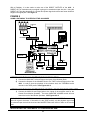
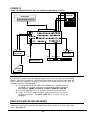
With a Patchbay, it is also easier to make use of the DIRECT OUTPUTS of the 1622. A
DIRECT OUT is used when only one signal is going to be recorded on tape at a time. Using the
DIRECT OUT has the advantage of a cleaner and quieter signal since there are fewer electronic
stages in the signal path. See Figure 8.
FIGURE 8
USING A PATCHBAY TO INTERFACE THE 1622 MIXER
OUTPUTS
1-8
INPUTS
1-8
PATCHBAY
STEREO OUTPUTS
1&2
LINE INPUTS
SUB OUT
CHANNEL INSERTS
MAIN OUT
MON
TAPE
MIC
DIRECT OUTPUT
RETURNS
SENDS
MONITOR SPKR
AMPLIFIER
IN
OUT
IN
IN
MICRO CUE
AMPLIFIER
IN
OUT
MICRO LIMITER
IN
OUT
OUT
EFFECTS UNIT
MIXDOWN DECK
INTERFACING THE 1622 MIXER TO THE MIXDOWN DECK
1) Connect the MAIN OUT Left and Right to the Inputs of the Mixdown Deck.
2) Connect the Outputs of the Mixdown Deck to the TAPE Left and Right jacks of the
1622. In order to hear the playback of the mixdown deck, the TAPE/MON switch
must be in the TAPE position. See Figures 6 & 8.
INTERFACING THE 1622 MIXER TO THE CONTROL ROOM MONITOR SPEAKERS
1) Connect the MON left and Right jacks to the inputs of the amplifier used for the
Control Room Monitor Speakers. The rotary MONITOR VOLUME control will now
control the level of the Monitor Speakers. See Figures 6 & 8.
PLEASE NOTE: If the TAPE/MON switch is in the MON position, the MASTER Faders must be
raised for signal to be heard. If the switch is in the TAPE position, only the playback signal from
the mixdown tape deck will be heard and the MASTER Faders will have no affect on the monitor
level.
INTERFACING THE 1622 MIXER TO A HEADPHONE AMP
15
There are two different sets of Sends on the 1622 MIXER. Sends 1 and 2, which are derived
before the Channel Fader, are used primarily for setting up a separate Cue mix for musicians to
overdub to, since any changes in the Channel Fader level will not affect the signal level of these
Pre-Fader Sends.
1) Connect the output of Sends 1 and 2 (SEND 1, SEND 2) to the Alesis Micro Cue
Amp or other suitable headphone amplifier. See Figures 6 & 8.
INTERFACING THE SENDS AND RETURNS OF THE 1622 MIXER TO EFFECTS
Sends 3, 4, 5, and 6 are derived post-fader which means that any changes in level in the fader
will also cause a change in level at the send as well. These sends can be used as "Effects
Sends" and connected to whatever outboard effects that are desired (reverbs, chorus, multieffects processors, delays) to be blended into the mix. These effects sends allow all 16 channels
to be processed simultaneously, as opposed to using a separate effect on each channel.
1) Connect the output of the effects sends (SEND 3, SEND 4, SEND 5, SEND
6) to the input or inputs of your outboard effects devices (MICROVERB II,
MIDIVERB III, QUADRAVERB).
2) The outputs of these effects devices are connected back into the console
through dedicated inputs called RETURNS. There are 8 returns, enough
for either 4 stereo, 8 mono, or any combination of mono or stereo devices.
If a mono device such as a delay is to be used, connect it to any of Returns
1 through 4 since these returns are pannable. Stereo effects devices can
be connected to either 1-2, 3-4, 5-6, or 7-8. See Figures 6 & 8.
PLEASE NOTE: Sends 1 and 2 can also be used as extra Effects Sends while mixing.
While sends 1 and 2 are pre-fader, and normally used for monitoring, they are perfectly suitable
as effect sends, especially during mixdown, when you will want to maximize your ability to add
effects to independent channels. Just remember that when you move a fader up or down you
won't be changing the level of the effect, since it is independent of fader movement on sends 1
and 2. As you change fader levels, you will need to make corresponding adjustments to sends 1
and 2 to maintain the desired balance between dry and effected signal.
INSERT INTERFACING
Inserts are used to connect signal processing devices into the signal path of a channel.
Normally, the device connected would be one that shapes the dynamics or tone of a signal, such
as a compressor, gate, or EQ, rather than an effects device such as a reverb.
It is also possible to insert one of these devices into the signal path of either the SUB MASTERS
or MAIN OUTPUTS since they also have INSERT jacks available. This is desirable when either
a group of instruments, or the entire mix, is to be processed.
Any INSERT jack of the 1622 MIXER is a stereo jack containing both an input and an output (the
output is the 1622's Send and the input is the 1622's Return).
1) To connect an outboard processor by way of the Insert requires a stereo plug to
operate properly.
2) The tip of the plug is the Send and will be connected to the input of the effects
device, and the ring of the plug is the Return and will be connected to the
output of the effects device or processor. See Figure 9.
FIGURE 9
16
WIRING OF INSERT CABLE
SEND (TO INPUT)
TIP (SEND)
RING (RETURN)
RETURN
(FROM
OUTPUT)
HOW TO ADJUST LEVELS
In order to ensure the cleanest signal with the least amount of background noise (hiss and hum),
it is extremely important for the proper levels to be maintained not only within the 1622 MIXER
itself, but throughout the entire audio system. Therefore, it's best to observe the following
guidelines when initially setting up your 1622 MIXER, and during daily use.
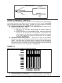
A) MAINTAIN PROPER INPUT LEVELS - To set proper input levels on either a mic or
line level signal, follow this procedure:
1) With mic or line level signal flowing through the channel, engage the
channel SOLO.
2) Observe the SOLO level on the MAIN LED Meter. Adjust the TRIM control
until the first red LED lights on the loudest peaks. If any distortion from
signal overload is still heard (due to possible brief peaks that don't register
on the meter), continue to decrease the TRIM control until the distortion
goes away. See Figure 11.
B) MAINTAIN PROPER FADER LEVELS - Ideally, both the input and output faders
should be run at about the "0" position (about the 3/4 of the way up the fader travel) if
possible. This position gives the greatest amount of headroom and lowest background
noise. It also allows for any additional increase or decrease in level that might be
required during mixing. Ultimately, the fader levels are dependent on the requirements
of the mix; the 3/4 level is only a starting point. See Figure 10.
FIGURE 10
IDEAL FADER POSITION DURING RECORDING OR MIXING
+10
+5
-5
-10
-15
-20
-25
-30
-35
1
2
3
4
CHANNEL FADERS
C)
MAINTAIN PROPER SYSTEM LEVELS - As a good rule of thumb, it is always best to
try to run most volume level controls of your other equipment as well. This will
17
decrease the possibility of overload distortion and keep the amount of background
noise to a minimum.
SEVERAL CAUTIONS!!
Even if you observe the above guidelines, it is still possible to run
into some distortion in the following instances:
1) If a large amount of EQ is used, it may be necessary to decrease either the
TRIM control, the Channel FADER, or both. The EQ is capable of adding
quite a bit of gain and is a frequent cause of overload distortion problems.
See Figure 11.
2) If several "hot" channels are assigned to a SUB MASTER, it is possible that
the SUB MASTER will overload. Once again, it may be necessary to
decrease either the TRIM controls, the Channel FADERS, or both, of each
of the channels assigned to the SUB MASTER. See Figure 11.
FIGURE 11
POSSIBLE POINTS OF SIGNAL OVERLOAD
7
1
CHANNEL, SUB MASTER,
AND MASTER INSERTS
TRIM
2
6
EQ
CONTROL ROOM
VOLUME
5
MASTER
3
FADER
CHANNEL
FADER
4
SUBMASTER
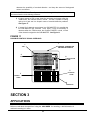
SECTION 3
APPLICATIONS
MULTITRACK RECORDING
Before we talk about the specifics of using the 1622 MIXER for recording, a brief discussion of
multitrack recording is in order.
18
INTRODUCTION TO MULTITRACK RECORDING
The function of the 1622 MIXER, or any recording console for that matter, is to provide control of
volume, tone, and spatial positioning of signals from microphones, electronic instruments, and
tape machines, then to route these signals to a monitor system and tape recorder so they can be
heard and recorded. Before the introduction of multitrack tape recorders, these signals had to be
mixed together as a "live" performance. If the desired performance wasn't correct because of a
musical mistake or balance problem, the performance had to be recorded again and again until
the performance was deemed satisfactory.
The introduction of multitrack tape machines changed this recording method forever. Most
recording today has evolved into a multi step process. These are:
RECORDING (or Tracking) - Instead of needing an entire band available to capture a live
performance, recordings can be made one instrument at a time and constructed in a building
block fashion. With the advent of drum machines and sequencers (such as the Alesis HR-16,
HR-16:B, and MMT-8) it is possible to build an entire song before ever having to record on tape.
Using this method of recording one instrument at a time also allows for fixing the mistakes
(normally called "punching in") of an incorrectly played part. By "punching in", or replacing, the
misplayed part, you can record a performance over and over again until it's perfect.
MONITORING - In order to properly record a performance, both the engineer, producer, and
all of the players must be able to hear the performance first. This is called Monitoring when
listening to the speakers in a control room, and Cue when the musicians are listening to
headphones while overdubbing.
Monitoring is a more complex operation than it might seem at first glance since there are many
mixes that can occur simultaneously. Often, there are 3 separate mixes (sometimes more)
happening simultaneously in order to complete the task of just a simple overdub. The
comprehensive systems and logistical layout of the 1622 MIXER will make it relatively easy for
you to accommodate even the most complex monitoring requirements. The following are a few
of the typical mixes that can occur during a session:
MULTITRACK MIX
The first mix would be the mix that is being recorded onto tape. This mix is
derived from the channel faders and the direct outs (channels 1-8, typically) or
the submaster outputs. These levels are normally adjusted so that the optimum
signal level reaches tape in order to insure the least amount of noise and
distortion. This level is usually about 0 VU (on the tape machine meters)
although signal levels as low as -10 VU may be appropriate for instruments with
high frequency transients, such as cymbals and snare drums.
MONITOR SPEAKER (CONTROL ROOM) MIX
If you were to only listen to the multitrack mix (see above), you would probably
find that it would be terribly out of balance since the optimum recording level is
the primary concern of that mix. Therefore, a second mix is required which is
called the monitor mix. This is a separate mix which provides the engineer with
a useful instrument balance and enables him to make changes and adjustments
to the mix (such as muting or soloing channels) without disturbing the signals
being recorded on tape. The 1622 MIXER can be configured to create a control
room mix. See Section 2 - INTERFACING TO THE MULTITRACK TAPE
RECORDER
CUE MIX
Many times a third separate mix is required as well. This mix is sent to the
musicians headphones for overdubbing and is called a CUE mix. This mix can
be radically different from what the engineer is listening to since the musician
may need certain instruments louder or even absent in the mix in order to cue
off of (hence the name). This mix is derived from the PRE-FADER SENDS,
19
which means that the headphone mix will not change if the fader level changes
while the engineer makes adjustments to his monitor mix. Since the 1622
MIXER has 2 Pre-Fader Sends, either 2 separate mono Cue mixes or 1 stereo
Cue mix can be provided.
MIXDOWN - After all of the desired musical parts have been performed and recorded
satisfactorily, the mixdown stage takes place. During this stage, the musical parts are blended
together, tonally enhanced with EQ and effects, positioned in the desired stereo spectrum with
the PAN controls, and finally recorded onto a DAT (Digital Audio Tape), 2 track reel to reel, or
cassette recorder. The 1622 MIXER provides a separate facility for both a mix to the mixdown
recorder, and for playback as well.
THE 1622 MIXER AND A 4 OR 8 TRACK TAPE DECK
USING THE 1622 MIXER TO RECORD:
A SINGLE SOURCE TO 1 TRACK
1) With a microphone or instrument connected to the desired input channel, set
the input level correctly. See Section 2, INTERFACING, and HOW TO
ADJUST LEVELS
2) Connect the DIRECT OUT of the input channel to the input of the desired tape
track. See Section 2, INTERFACING,
3) To monitor (listen to) the track through the Multitrack Tape Deck, place the
desired track of the tape machine into "source" or "input" and raise the Channel
Fader of the 1622 MIXER where the tape return from the Multitrack is
connected; i.e Track 1 to Channel 9, Track 2 to Channel 10, etc. (See Section
2, INTERFACING, and HOW TO ADJUST LEVELS) Follow instructions for
playback.
OR FOLLOW THE INSTRUCTIONS FOR TWO OR MORE SOURCES TO 1 TRACK.
TWO OR MORE SOURCES TO 1 TRACK
1) With microphones or instruments connected to the input channels, set the input
levels correctly. See Section 2, INTERFACING, and HOW TO ADJUST
LEVELS.
2) If more than 1 instrument is to be recorded on 1 track at the same time, assign
it to a SUB MASTER by switching the SUB switch to the "On" position on the
desired channel.
3) Use the PAN control on all of the assigned channels to position the channels
fully either to the left or right. If the panning is fully left, then you will be using
SUB MASTER 1 (the left). If the panning is fully to the right, then you will be
using SUB MASTER 2.
4) Connect the output of the SUB MASTER of the 1622 MIXER to the input of the
track to be recorded on the Multitrack Tape Deck.
5) The SUB MASTER Fader will now control the level going to tape. For cleanest
recording, the SUB MASTER Fader should be adjusted so that the level going
to tape should reach 0 VU on peaks on the meters of the Multitrack Tape Deck.
The exception to this would be for percussive instruments with lots of high
20
frequency information, such as cymbals, which should be recorded at -10 or -15
VU to prevent unwanted peaks which the meters won't indicate.
6) Be sure that the SUB ASSIGN switch (the one above the SUB MASTER Fader)
is in the "Off" position. Otherwise, the signal will be assigned twice to the
Master buss and may cause the signal to be too loud in the Monitor Mix.
7) To monitor (listen to) the track through the Multitrack Tape Deck, place the
desired track of the tape machine into "source" or "input" and raise the Channel
Fader of the 1622 MIXER where the tape return from the Multitrack is
connected; i.e Track 1 to Channel 9, Track 2 to Channel 10, etc. (See Section
2, INTERFACING, and HOW TO ADJUST LEVELS). Follow instructions for
playback.
2 OR MORE SOURCES TO 2 TRACKS
1) With microphones or instruments connected to the input channels, set the input
levels correctly. See Section 2, INTERFACING, and HOW TO ADJUST
LEVELS.
2) Assign the channels to a SUB MASTER by switching the SUB switch to the
"On" position on the desired channel.
3) Since the tracks are to be recorded in stereo (you will have to record
simultaneously on 2 tracks of the tape recorder), pan SUBMASTER 1 hard left,
pan SUMBASTER 2 hard right, then pan the channels to the desired position in
the stereo spectrum using the channel pan controls.
4) Connect the output of the SUB MASTERS of the 1622 MIXER to the inputs of
the 2 tracks to be recorded on the Multitrack Tape Deck.
5) The SUB MASTER Faders will now control the level going to tape. For
cleanest recording, the SUB MASTER Faders should be adjusted so that the
level going to tape should reach 0 VU on peaks on the meters of the Multitrack
Tape Deck. The exception to this would be for percussive instruments with lots
of high frequency information, such as cymbals, which should be recorded at 10 or -15 VU to prevent unwanted peaks which the meters won't indicate.
6) Be sure that the SUB ASSIGN switch (the one above the SUB MASTER Fader)
is in the "Off" position. Otherwise, the signal will be assigned twice to the
Master buss and may cause the signal to be too loud in the Monitor Mix.
7) To monitor (listen to) the track through the Multitrack Tape Deck, place the
desired track of the tape machine into "source" or "input" and raise the Channel
Fader of the 1622 where the tape return from the Multitrack is connected; i.e
Track 1 to Channel 9, Track 2 to Channel 10, etc. (See Section 2,
INTERFACING, and HOW TO ADJUST LEVELS).
Follow instructions for
playback.
CAUTION:
BE SURE OF THE FOLLOWING WHEN RECORDING!
A) Be sure that the SUB ASSIGN is NOT switched to the "On" position on the
Tape Return Channels. This will cause feedback to occur.
B) Be sure that the MASTER ASSIGN is NOT switched to the "On" position on
the Input Channels. This will cause the monitoring to be false since the
signal will be heard from two sources; the Input Channels and the Tape
Return Channels.
21
RECORDING TIPS
•
For cleanest recording, the SUB MASTER Faders (or Channel Faders if the DIRECT
OUTPUTS are being used) should be adjusted so that the level going to tape should
reach 0 VU on peaks on the meters of the Multitrack Tape Deck. The exception to this
would be for percussive instruments with lots of high frequency information, such as
cymbals, which should be recorded at -10 or -15 VU to prevent unwanted peaks which
the meters won't indicate.
•
If signal peaks cause the record meter to vary by more than 10VU, a limiter, such as the
Alesis MICRO LIMITER, should be used on that channel to even the peaks out. In
general, things will sound better if the meters remain at roughly the same level
throughout the recording.
HOW TO PLAYBACK FROM MULTITRACK
1)
Place the Multitrack Tape Deck into the "Tape" or "Playback" position.
2)
Raise the Channel Faders that are being used as Multitrack Tape
Returns.. This will usually be Channels 9 through 16. See Section 2,
INTERFACING.
3)
Assign the Channel Faders that are being used as Tape Returns by
switching their "MASTER" assign switches to the "On" position.
4)
Raise the MASTER Faders to where the peaks briefly light the red LED's.
5) Turn the rotary MONITOR VOLUME pot to the desired volume level.
The TAPE/MON switch must be in the MON position.
HOW TO SET UP A CUE MIX
The Cue mix will be created using SENDS 1 & 2 on the 1622 because the signals from these
sends are derived Pre-Fader (See Section 1). SENDS 1 and 2 will have to be connected to a
headphone amplifier such as the Alesis MICRO CUE AMP (as described in Section 2,
INTERFACING THE 1622 MIXER TO A HEADPHONE AMP) before proceeding to the following
steps.
1)
While monitoring on headphones, turn up SEND 1 and SEND 2 (for a
stereo mix), or just SEND 1 (for mono) on the Channels used as Tape
Returns until the desired Headphone Mix is obtained.
Normally, an easy headphone mix to overdub to will be similar to the
Control Room mix (See the following; "Mixdown Basics") except that the
vocal or instrument that is being recorded will be a bit louder in the mix.
Sometimes, the Kick or Snare is also raised a bit louder than normal to
make it easier to stay in time or "lay in the pocket".
2)
Use SEND MASTER 1 and 2 to increase or decrease the overall volume.
22
PLEASE NOTE: For quietest operation with the greatest headroom, it's best to run the
individual channel SENDS at about the 3/4 level and the SEND MASTERS at about half
or less.
MIXDOWN BASICS
Below is a simplified step by step way to establish a mix. For a more complex (but better
sounding) method, see the following "How to Create a Great Mix".
1) Raise the Channel Faders that are being used as Tape Returns to the
desired levels.
2)
Adjust the EQ as needed(refer to HOW TO ADJUST LEVELS in Section
2)
3)
Add the amount of effects desired by adjusting the SEND levels of each
Tape Return Channel. If required, adjust the MASTER SEND levels to
eliminate overload of outboard effects. For quietest operation with the
greatest amount of headroom, it's best to run the individual channel
SENDS at about the 3/4 level and the SEND MASTERS at about half or
less.
4)
Raise the effects RETURN level controls and pan as desired (typically
hard left and hard right).
5)
Adjust the MASTER Faders so that the desired level is sent to the
Mixdown Tape Machine.
HOW TO CREATE A DEPENDABLE MIX
Creating a mix is easy; creating a great mix, one that jumps off of the tape, is a lot harder.
There are those engineers who are in demand just for mixing because their sense of balance
between instruments causes the mix to come alive with excitement. Although outboard effects
and tonal adjustment are important, you'd be surprised at how good a dry (meaning no effects or
EQ) mix can be if the balances between the parts are right. When you add effects and EQ it will
sound that much better.
Since much of the art of mixing is totally subjective and up to the taste of the engineer, a basic
balance between instruments is necessary first before any tonal or effect enhancements can
really be effective. So we've decided to include a method to help you quickly create a
"dependable" mix; one that sounds good no matter what speakers you mix or play back on.
It would be easy to give a basic reference mixing formula just for the instruments normally found
in pop music (Kick, Snare, Hat, Percussion, Bass, Guitar, Synthesizers, etc), but with a addition
of a little orchestration theory, this method can be applied to any type of music regardless of the
instruments used.
23
A BIT OF MIXING THEORY
Any mix can be separated into 5 parts or "Elements". It is the balance between these elements
that is responsible for the mix balance. The five mix Elements can be broken down as follows:
ELEMENT 1 - RHYTHM
The Rhythm is usually just the bass guitar and drums but really can be any instruments that
keeps steady time. Too many instruments in the Rhythm element causes a mix to be too "busy"
and as few as 1 instrument can be more than sufficient in some cases. The Rhythm instruments
in our example are: Kick, Snare, and Bass.
ELEMENT 2 - MOTION
Motion is distinctly different from Rhythm. Where the Rhythm Element is responsible for
keeping the beat (and time), the Motion Element usually fills in the rhythmical spaces where the
Rhythm instruments are not playing. Motion instruments are usually Rhythm Guitars, Percussive
Keyboards such as Clavinets or pianos, or Percussion instruments. Motion instruments tend to
play double-time of the Rhythm instruments.
ELEMENT 3 - PAD
The Pad Element is usually only one instrument that plays long sustaining notes or chords that
support the other elements. These instruments are usually strings, organs, sustained guitar
chords, or a synthesizer.
ELEMENT 4 - MELODY
The Melody Element is the focal point of the mix. This is usually a lead vocal or solo instrument.
ELEMENT 5 - FILLS
Fills are instrumental or percussion (occasionally vocal) passages that occur between the melody
line.
Most of the time, only 4 Elements should occur at any one time, with the Melody and Fills
alternating between each other (they may overlap a bit) but usually never occurring at the same
time.
LET'S MIX
To create your mix, just do the following. Remember that this is only a reference point; each
song is unique and calls for different balances. Use the following as a starting point.
1)
Begin with all Faders in the "Off" position. Set the MASTER Faders to the
"0" point on their travel.
2)
Raise the Kick Drum Channel Fader until the LED meters read "-2".
3)
Now mute the Kick Drum Channel by switching the Mute Switch to the
"Off" position so the Kick can no longer be heard. DO NOT MOVE THE
FADER! Just mute the Kick Channel.
4)
Raise the Snare Drum Fader until the LED meters read "0".
5)
Mute the Snare Drum the same as the Kick.
6)
Raise the High Hat Fader until it reads "-15" on the LED meter. If any
cymbals (ride or crashes) occur in the song, set them also to read "-15".
7)
Mute the High Hat and Cymbals.
8)
Raise the Tom Channel Faders. Set so that the LED meter indicates "0".
9)
Mute the Toms
24
10) Bring up the Bass Guitar Channel Fader. Set so that the meters read "-6".
11) Mute the Bass
12) Raise the Channel Faders with the Motion instruments. Set so that the
meters read "-10 " unless percussion instruments such as cowbell, triangle,
or shaker are involved in, which case the meters should read "-15".
13) Mute the Motion instruments.
14) Raise the Channel Faders with the Pad instruments. Set so the meters
read "-30".
15) Mute the Pad instruments.
16) Raise the Channel Faders with the Melody and solo instruments. Set so the
meters read "-8".
17) Mute the Melody instruments.
18) Raise the Channel Faders with the Fill instruments. Set so the meters read
"-10".
19) Unmute all channels and make balance adjustments as necessary.
The above can be done very fast once you get the hang of it. Usually, it is done at least twice
when "getting up" a mix. The first time is without effects or EQ to see what, if anything the mix
needs, then a second time after all of the effects and EQ have been added.
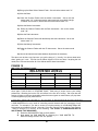
FIGURE 12
MIX LEVEL REFERENCE CHART
RELATIVE MIX LEVELS
RHYTHM
Snare
0 VU
VU
Kick
-2 VU
VU
Hat
-15 VU
Cymbals -15 VU
Bass Gtr -6 VU
MOTION
PAD
MELODY
Rhythm Gtr -10 VU Keys
-30 VU Lead Vocal -8 VU
Perc Keys -10 VU
Strings
-30 VU Solos
-8 VU
FILLS
All
Inst.-10
Toms
0
Percussion -15 VU
Once again, THIS IS ONLY A STARTING POINT. Each song is unique as are your mixing
preferences. Blending the levels, EQ, and effects is the fine art of mixing. We hope that this
section will help you achieve dependable mixes that sound good no matter where you play them
or what equipment you play them back on.
HOW TO GROUP SEVERAL CHANNELS TOGETHER WHEN MIXING
A SUB MASTERcan be very useful in controlling several channels with the movement of only
one fader. For example, if you wish to control your rhythm section via a SUB MASTERand the
instruments were located on tracks 1 through 4 (raise the Channel Faders used as Tape Returns
, faders 9 through 12 to monitor), do the following: See Section 2, INTERFACING WITH A
MULTITRACK TAPE RECORDER
1) Raise the SUB MASTER Fader to the 0 position.
2) Now assign the SUB MASTER by switching the "SUB MASTER TO
MASTER" assign switch to the "On" position.
25
3)
Unassign the Channel Faders that are being used as Tape Returns (in this
case Channels 1 through 4) by switching the "MASTER" assign switch to
the "Off" position.
4) Now assign the Channel Faders that are being used as Tape Returns by
switching the "SUB MASTER" assign switch to the "On" position.
5) Raise the Channel Faders that are being used as Tape Return to the
desired balance. The SUB MASTER Fader will now control those
channels assigned to it.
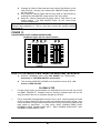
PLEASE NOTE: Ideally, the SUB MASTER Fader should always be higher than the
Channel Faders assigned to it. This is a sure way to prevent any possible overload.
See Figure 13.
FIGURE 13
PROPER FADER LEVELS DURING SUBGROUPING
(SubMaster Higher than the Channel Faders)
KICK
SNARE
1
L-DRUMS-R
2
+10
+10
+10
+5
+5
+5
-5
-5
-5
-10
-10
-10
-15
-20
-15
-20
-15
-20
-25
-30
-25
-30
-35
-35
-25
-30
-35
1
2
3
CHANNEL
FADERS
4
SUBMASTERS
HOW TO PLAYBACK A MIX FROM THE MIXDOWN TAPE DECK
1)
Place the TAPE/MON switch of the 1622 MIXER to the TAPE position.
See Section 1, TAPE/MON SWITCH, and Section 2
2)
Turn the rotary MONITOR VOLUME pot to the desired volume level. See
Section 1, MON VOLUME
PLAYBACK TIPS
•
For best mixing results, get comfortable at a reasonable level (not too loud; not too soft)
and DON'T CHANGE IT! Playback levels are extremely important since the ear can
easily be tricked if the level is constantly changed up and down.
•
Find a comfortable mixing/playback level that isn't too loud. Almost anything will sound
good if it's played back loudly but will usually not translate well at softer volumes. Also,
loud levels cause ear fatigue which means that the ear will be deceived by balances and
tonal quality of instruments.
In other words, WHAT SOUNDS GOOD LOUD,
PROBABLY WON'T SOUND GOOD SOFT; WHAT SOUNDS GOOD SOFT, WILL
PROBABLY SOUND GREAT LOUD.
26
SOUND REINFORCEMENT
The 1622 MIXER performs well in a Sound Reinforcement application. Here are some helpful
hints to help you get the most out of your unit.
SOUND REINFORCEMENT APPLICATIONS IN MONO
Most sound reinforcement applications work best in mono. This is because so few members of
the audience are actually seated in the ideal spot to hear the balance of a stereo sound system
effectively. Also, a stereo sound system is much more difficult to mix, especially if you don't
have a sound man.
There are two ways to configure the 1622 MIXER in order to achieve a mono mix.
METHOD A
1) Pan all of the input channels all the way to the left (or all the way to the right).
See Section 1, PAN POT
2) A mono mix will now be present at the Left MASTER Fader (or Right MASTER
Fader if all of the input channels were panned that way).
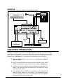
This method will make RETURNS 6 and 8 unavailable (or 5 and 7 if all of the input channels are
panned to the right) since these returns are dedicated to the right MASTER Fader. Use the
following method if all 8 RETURNS are needed.
METHOD B
1) Pan all of the input channels to the center.
2) Use a Y cord from the MAIN OUT jacks on the backpanel. The output is now
mono and all eight RETURNS are available for use. See FIGURE 14.
27
FIGURE 14
MONO OUTPUT FROM THE 1622
RETURNS
MIXER FOR SOUND REINFORCEMENT USING ALL 8
INSTRUMENTS
OR
MICROPHONES
LINE INPUTS
SUB OUT
CHANNEL INSERTS
MAIN OUT
MON
TAPE
RETURNS
SENDS
IN
"Y" LEFT AND RIGHT
TOGETHER FOR MONO
MIC
DIRECT OUTPUT
IN
IN
STAGE
MICRO LIMITER
MONITOR AMP
IN
IN
OUT
OUT
OUT
HOUSE
EFFECTS UNIT
SPKR AMP
MONITOR
SPKR
USING THE SUB MASTERS
The SUB MASTERS are extremely useful in sound reinforcement work. A SUB MASTER can
be very useful in controlling the level of several channels with the movement of only one fader.
For example, if you wished to control your group vocals via a SUB MASTER, and the vocal mics
were located on channels 1 through 6, do the following:
28
1) Raise the selected Channel Faders to the desired levels See Section 2,
HOW TO ADJUST LEVELS
2) Unassign the selected Channel Faders by switching the "MASTER" assign
switch to the "Off" position. See Section 1, MASTER ASSIGN SWITCH
3) Now assign the Channel Faders by switching the "SUB MASTER" assign
switch to the "On" position. See Section 1, SUB MASTER TO MASTER
ASSIGN SWITCH
4) Now assign the SUB MASTER by switching the "SUB MASTER TO
MASTER" assign switch to the "On" position. The SUB MASTER fader will
now control those channels assigned to it.
LINE INPUTS USED AS ADDITIONAL MIC INPUTS
The 1622 MIXER is not limited to only 8 microphone inputs. Besides the XLR connections on
Input Channels 1 through 8, Channels 9 through 16 may also be used as additional microphone
inputs. This is accomplished by using the 1/4" plug as the microphone input and will require
either an XLR to 1/4" adapter or a mic cable with a 1/4" plug on the end. See Figure 14.
USING THE SUB MASTERS FOR SEPARATE OUTPUTS
There may be situations that call for a separate controlled output level beside the ones available
from the MAIN OUTPUT, such as when the 1622 MIXER is used as an on-stage keyboard
mixer. In this case, one set of outputs will feed the keyboard players on-stage amplifier, and the
2nd set of outputs will feed the house sound system. See Figure 15.
In order to accomplish this, do the following :
1) Raise the Channel Faders to the desired levels
2) Assign the Channel Faders by switching both the "MASTER" assign switch
and the "SUB MASTER" assign switch to the "On" position.
3) Now unassign the SUB MASTER by switching the "SUB MASTER TO
MASTER" assign switch to the "Off" position. The SUB MASTER Fader
will now separately control one set of outputs while the MASTER Faders
will control the other.
29
FIGURE 15
USING THE SUB MASTERS OF THE 1622 MIXER FOR SEPARATE OUTPUTS
DRUM
MACHINE
KEYBOARDS
LINE INPUTS
SUB OUT
CHANNEL INSERTS
MAIN OUT
MON
IN
MIC
DIRECT OUTPUT
TAPE
RETURNS
SENDS
IN
IN
STAGE
MONITOR AMP
OUT
MICRO LIMITER
IN
IN
OUT
OUT
HOUSE
MIXING CONSOLE
EFFECTS UNIT
MONITOR
SPKR
STAGE MONITOR MIX FROM THE PRE-FADER SENDS
It is possible to create up to two separate stage monitor mixes by using the PRE-FADER
SENDS. Although it is possible to use the Post-Fader Sends as well, the Pre-Fader Sends are
better suited to this application since any movement of the Channel Faders will not affect the
Pre-Fader send level. See Figure 16.
1) On the Input Channels, turn SEND 1 and SEND 2 (for 2 separate mixes) or
just SEND 1 (for a single, mono mix) until the desired balance is obtained.
See Section 1, SENDS, and Section 3, HOW TO CREATE A CUE MIX
2) Use SEND MASTER 1 and 2 to increase or decrease the overall volume.
3) Usually, a 1/3 octave graphic equalizer is patched into the line to notch out
feedback frequencies. The Alesis M-EQ 230 is a perfect unit for this
application.
DEDICATED MIDI KEYBOARD MIXER
The use of the 1622 as a dedicated mixer in a MIDI keyboard setup is very similar to a sound
reinforcement application except that the MAIN OUTputs will usually be in stereo rather than
mono. See Figure 16.
30
FIGURE 16
THE 1622 MIXER USED AS A DEDICATED KEYBOARD MIXER
DRUM
MACHINE
KEYBOARDS
LINE INPUTS
SUB OUT
CHANNEL INSERTS
MAIN OUT
MON
MIC
DIRECT OUTPUT
TAPE
SENDS
IN
EFFECTS
UNIT
RETURNS
IN
IN
MIXING CONSOLE
OR
SOUND SYSTEM
OUT
MICRO LIMITER
IN
OUT
OUT
VIDEO POST-PRODUCTION
The 1622 MIXER can easily be used in editing bays or video post-production facilities. The
availability of separate output jacks on the SUB MASTERS make the unit ideal for making
simultaneous mix-minus feeds. A mix-minus feed, which is used for international versions of a
film or video, is a separate mix containing all music and effects, but no dialog (which is usually
dubbed in later). See Figure 17. To accomplish a mix-minus feed, do the following:
1) Raise the Channel Faders to the desired levels. See Section 2, HOW TO
ADJUST LEVELS
2) Assign the Channel Faders by switching both the "MASTER" assign switch
and the "SUB MASTER" assign switch to the "On" position. See Section 1
3) Unassign the Input Channels that contain the dialog (or any information not
desired in the mix-minus feed) by switching the "SUB MASTER" assign
switch to the "Off" position.
4) Now unassign the SUB MASTER by switching the "SUB MASTER TO
MASTER" assign switch to the "Off" position. The SUB MASTER Fader
will now separately control the mix-minus outputs while the MASTER
Faders will control the full composite output.
31
FIGURE 17
USING THE 1622 MIXER FOR A MIX MINUS OUTPUT
VTR'S
CART MACHINES
VTR
IN
OUT
OUT
MIX-MINUS
LINE INPUTS
SUB OUT
CHANNEL INSERTS
MAIN OUT
MON
IN
TAPE
MIC
DIRECT OUTPUT
RETURNS
SENDS
IN
IN
OUT
MICRO LIMITER
VTR
IN
IN
MONITOR
SPKR AMP
IN
OUT
OUT
EFFECTS UNIT
SECTION 4
TROUBLESHOOTING
NO SOUND
NO SOUND WHEN CHANNEL IS SOLOED
1) Plug is inserted into LINE input, which has priority over MIC input.
2) Open circuit in the INSERT signal path. Remove plug from INSERT jack.
NO SOUND WHEN MONITOR LEVEL TURNED UP
1) MONITOR MUTE is engaged. Switch to "Off" position.
2) SOLO is activated. If SOLO LED is lit, find the channel soloed and switch to "Off" position.
3) TAPE/MON Switch in the wrong position. Swith to MON position to hear the console signal.
Switch to TAPE position to hear the mixdown tape deck.
OVERLOAD PROBLEMS
DISTORTION HEARD WHEN INPUT CHANNEL IS SOLOED
1) Input too hot. Decrease TRIM level.
2) Excessive use of EQ. Decrease TRIM level or EQ levels.
3) Cable fault. Check the cable from the mic or instrument.
4) Trouble at the source. Try a different mic or instrument.
DISTORTION IS BEING RECORDED ONTO TAPE, BUT DISTORTION NOT HEARD WHEN INPUT
CHANNEL IS SOLOED
1) SUB MASTER is overloaded. Decrease the fader levels of the channels assigned to the
SUB MASTER.
32
2) Tape Machine input is overloaded. Set tape recorder input level control or SUB MASTER
levels so that the meters of the tape deck hit 0 VU or less when recording.
3) Monitor input of the 1622 MIXER is overloaded. Decrease TRIM control or output of
Multitrack Tape Deck.
DISTORTION AT MIXDOWN MACHINE OR SOUND SYSTEM
1) Input Channel is overloaded. Solo each channel until distortion is found, then decrease
either TRIM level or Fader level or both.
2) SUB MASTER is overloaded. Decrease the Fader levels of the channels assigned to SUB
MASTER.
3) MASTER Faders are overloaded. If LED meters are in the red, decrease MASTER Fader
level until distortion disappears. If LED meters are not in the red yet distortion is still heard,
decrease all Input Channel Faders.
4) Overloaded Return. Decrease output level of effects device or decrease RETURN level.
5) Effects unit is overloaded. Decrease output of SEND MASTER level or input level of
effects device.
DISTORTION ON THE RETURNS
1) Overloaded return. Decrease output level of effects device or decrease RETURN level.
2) Effects unit is overloaded. Decrease output of SEND MASTER level or input level of
effects device.
SECTION 5
GROUNDING
Grounding problems ("Ground Loops") are probably one of the most common and annoying
problems that plague not only home studios, but professional and commercial studios and sound
reinforcement systems as well. While there are methods to virtually eliminate ground loops and
stray radio frequency interference, most of the professional methods are expensive and involve
installing a separate power source just for the sound system. Since this is far from practical in
the majority of situations that the 1622 MIXER will be used in, here are some easy helpful hints
that a professional studio installer might use to keep those stray hums and buzzes to a minimum.
1) KEEP ALL ELECTRONICS OF THE SOUND SYSTEM ON THE SAME AC ELECTRICAL
CIRCUIT.
Without getting too technical, most stray hums and buzzes happen as a result of different parts
of the sound system being plugged into outlets of different AC circuits. If any noise generating
devices such as air conditioners, refrigerators, neon lights, etc. are already plugged into one of
the circuits, you then have a perfect condition for stray buzzes.
Since most electronic devices of a sound system don't require a lot of current (except for power
amplifiers), it's usually safe to run a multi-outlet box or two from a SINGLE wall outlet and plug in
all of the components of your system there.
2) KEEP AUDIO WIRING AS FAR AWAY FROM AC WIRING AS POSSIBLE.
Many hums come from audio cabling being too near AC wiring. If a hum occurs, try moving the
audio wiring around to see if the hum ceases or diminishes. If it's not possible to separate the
audio and AC wiring in some instances, make sure that the audio wires don't run parallel to any
AC wire (they should only cross at right angles if possible).
3) TO ELIMINATE A HUM IF THE ABOVE HAS FAILED:
A) Disconnect the power from all outboard devices and tape machines except
for the 1622 MIXER and control room monitor power amp.
B) If the hum still exists, flip the polarity of the plug (turn it around in the
socket) of the power amp and 1622 MIXER until the hum disappears or is
33
diminished. If the power amp has a grounded type plug (3 pin), use a 3 to
2 pin adapter (ground lift) instead of flipping the plug.
C) Plug in each tape machine and outboard effects device one at a time.
Either use a ground lifter or flip the polarity until the quietest position is
found.
D) You should've done this in the first place, but in case you haven't yet, make
sure that all of the audio cables are in working order. Cables with a
detached ground wire will cause a very loud hum!!
34
SECTION 6
SPECIFICATIONS
ELECTRICAL CHARACTERISTICS
FREQUENCY RESPONSE
HARMONIC DISTORTION
CROSSTALK
SIGNAL TO NOISE RATIO
+0/-2 dBV 20 to 20KHz
Better than .015% @ 1KHz @ 0dBV
-91 dBV Channel to Channel @ 1KHz @ 0dBV
Worst Case -78dBV Master or Monitor with 16 inputs @ unity
gain @ 0dB
INPUTS
GAIN
MAXIMUM LEVEL
IMPEDANCE
OUTPUTS
MAXIMUM LEVEL
IMPEDANCE
+70 dB Mic Input to Master Output
+17dBV
3K Mic/1M Line
+17dBV
500 All Outputs
FRONT PANEL
CONTROLS
Trim x 16
Hi EQ x 16
Lo EQ x 16
Pre-Fader Sends 1 &2 x 16
Post Fader Sends 3 - 6 x 16
Pan Control x 18
Channel Fader x 16 Send Masters 1 through 6
Return Level 1 - 8
Return Pan 1 - 4
SubMaster Faders 1 & 2
Master Faders 1 & 2 Monitor Volume
INDICATORS
Solo LED
15 Segment LED VU Meters x 2
Power LED
SWITCHES
Master Assignment x 16
Mute x 16
Tape/Master
SubMaster to Master Assignment
SubMaster Assignment x 16
Solo x 16
Control Room Defeat
REAR PANEL
JACKS
Microphone Inputs - XLR
Main Outputs - mono 1/4"
Line Inputs - mono 1/4"
Main Out Inserts - 1/4"TRS
Aux Sends - mono 1/4"
Sub Out - mono 1/4"
Channel Inserts - 1/4" TRS
Sub Out Inserts - 1/4" TRS
Direct Outs - mono 1/4" Monitor Outputs - mono 1/4"
Tape Returns - mono 1/4" Aux Returns - mono 1/4"
Power - 5 pin XLR
Headphone - 1/4" TRS
SWITCHES
Main Outputs +4/-10dBV Operation
On/Off
POWER REQUIREMENTS External 9VAC, UL approved and made in USA
DIMENSIONS (W x H x D) 19" x 21" x 1.5" - 6"
WEIGHT appx.14lbs
35
GLOSSARY
1/4" plug - Also known as a phone plug, this is the common "guitar" type plug used on most
electronic music instruments and amplifiers. All connections except for the microphone inputs
on the 1622 MIXER are done with 1/4" plugs. See Figures 9 & 30.
Balanced Line - A circuit incorporating 2 wires to carry the signal voltage, wrapped with a
shield that is grounded. This method is preferred over an unbalanced type line (see unbalanced)
because it cancels any stray hum or noise that may be induced in the line from outside sources.
An input or an output using an XLR type connector (see XLR) is usually, but not always,
balanced. A 1/4" phone plug is almost always unbalanced. The 8 microphone inputs of the 1622
MIXER are balanced.
Buss - A buss is a junction line where a number of signal lines are commonly joined. It is
similar in concept to the way that electricity arrives at your house. Each house on the block is
connected to a line on the pole outside in order to draw electricity. The power line on the pole is
a buss line. The 1622 MIXER has 4 busses; the MASTER Left and Right, and the SUB GROUP
Left and Right. See Figure 18.
FIGURE 18
A TYPICAL BUSS LINE
BUSS LINE
TO OUTPUT
JACK
BUSS MASTER
OR
SUBMASTER
CHANNEL FADERS
Chorus - A popular signal processing effect, Chorus attempts to simulate the sound of a group
of instruments by introducing minute changes in pitch and time. This is done by splitting the
signal of an instrument into two parts. One signal remains unchanged while the second is
slightly delayed in time and detuned in pitch.
Compressor/Limiter - A compressor/limiter, which can be thought of as an automatic fader,
very quickly reduces gain and attenuates the signal once it exceeds a predetermined level. The
number of dB increase of the input signal needed to cause a 1 dB increase in the output signal of
the compressor/limiter is called the "Compression Ratio". Thus, for a ratio of 4 to 1, an 8 dB
increase of the input produces a 2 dB increase in output.
A low compression ratio (2:1 to 8:1) causes the compressor/limiter to act in the compression
mode. A compressor is usually used to even out the volume differences of an instrument or
36
vocal. A compression ratio of 10:1 or above changes the compressor into a limiter. A limiter is
used to prevent short term peaks, which add little information to program material, from
overloading amplifiers or tapes.
The Alesis MICRO LIMITER is an example of a
compressor/limiter.
Cue Mix - The mix sent to musicians studio headphones is called the Cue Mix. This mix is
usually different from the one that is being heard in the control room, since the musicians
frequently require certain instruments to be of a different volume or absent altogether in order to
"cue" off of. The 1622 MIXER is capable of supplying either 2 mono or 1 stereo Cue Mix.
dBV - Decibels per Volt. This is a unit of measurement normally applied when measuring the
inputs and outputs of most modern sound equipment. Technically speaking, this is measured
when a low impedance source is fed into a high impedance input, as is the case in nearly all
current sound equipment. +4dBV = 1.4 volts AC, 0dBV = .778 volts AC.
Delay - An electronic effect in which the original signal is repeated and mixed back in with the
original signal. Usually, the number of repeats and the length of time between the repeats can
be adjusted. Also sometimes known as Echo.
Direct Outputs - This jack contains the amplified (and EQ'ed) signal of only one channel,
which has not been mixed together with other signals in the mixer. This is generally used to feed
a single track of a tape machine. Because the Direct Output is the path with the least amount of
circuitry and therefore the lowest possible background noise, it is most desirable to use. The
1622 MIXER has a Direct Output on each of the first 8 Input Channels.
Distortion - Any deviation in the amplified signal from its original. Distortion may take many
forms such as certain frequencies becoming louder or softer after being amplified (frequency
response), unwanted signal artifacts when two or more signals are amplified at the same time
(intermodulation distortion), or certain harmonics of a signal being favored over others (harmonic
distortion).
Echo - See Delay.
Edit Bay - An Edit Bay is the equivalent of a video mixdown studio, where shots from different
reels are assembled onto a master reel. At this point, video effects such as wipes and fades are
also added.
Effects - The term used for signal processing that is added to a signal to enhance its tonal
quality. These effects may be reverb, echo, EQ, compression, chorusing, flanging, etc.
Equalization (EQ) - Equalization is the ability to adjust the tonal balance of a signal. This can
be of a very broad nature, such as the bass and treble controls of a home stereo unit, or of a
finely tuned nature, such as a graphic equalizer. The 1622 MIXER has 2 bands of shelving type
EQ (see shelving) per Input Channel.
Fader - The Channel Fader determines the overall volume level of the channel. It is normally
best to keep this Fader at about the 3/4 level for best headroom and lowest background noise.
Feedback - Whenever a portion of an amplifier's output is returned to its input, and therefore reamplified, a loud howl called "feedback" is created. Most commonly, this occurs in sound
systems when the output of the loudspeakers is picked up again and again by a microphone
forming a feedback "loop".
Flanging - First used in the sixties, "flanging" was achieved by the use of two tape recorders
that would record and play back the same program in synchronization. By alternately slowing
down one tape machine, and then the other, different frequency cancellations would occur.
Since the slowing down of the tape machines was done by hand pressure against the flanges of
the tape supply reels, the term "flanging" came into being. Today, flanging can be closely
simulated by most outboard effects processors such as the Alesis MIDIVERB II, MIDIVERB III,
37
or QUADRAVERB. The effect of flanging, either electronically or mechanically done, is
achieved by slightly delaying a signal, then constantly varying the amount of time delay. The
delayed signal is then mixed back with the original signal to produce the "swishing" or "tunneling"
sound.
Gate - See "Noise Gate".
Graphic Equalizer - Seen on sound systems, some home stereos, and many guitar type
amplifiers, this device gets its name from the fact that the control settings actually form a graph
of the frequency spectrum. While shelving equalizers work on broad sections of the frequency
bandwidth, a graphic equalizer divides the frequency spectrum into sections called bands which
are normally measured in musical octaves. An example of a graphic equalizer is the Alesis MEQ 230 .
Ground Lift - An adapter for an AC line plug that converts it from 3 pin operation to 2 pin. This
is frequently used to avoid ground loops (see Ground Loops).
Ground Loops - When a sound system or recording system has a loud hum or buzz, a Ground
Loop is usually the cause. Ground Loops are created by having more than one ground point in a
sound system. (See Section 5 - GROUNDING).
Headroom - The amount of available operating level before a circuit is overloaded and begins
to distort. For example, the nominal operating level of the 1622 MIXER is +4dBV and the
maximum output level is +20dBV which means that there is 16dB of headroom available. If the
nominal operating level is -10dBV and the maximum output level is +20dBV, then there is 30dB
of headroom available.
High Impedance - Any impedance which is 10,000 ohms or more is considered a High
Impedance. The inputs of most audio devices are High Impedance. All inputs except the
microphone inputs of the 1622 MIXER are High Impedance.
Inserts - Inserts are used to connect signal processing devices into the signal path of a single
channel. Normally, this is a device that shapes the dynamics or tone of a signal, such as a
compressor, gate, or EQ, rather than an effects device such as a reverb.
An insert consists of both an input and an output and is used to place an outboard effects device,
such as a compressor, EQ, or chorus, into the signal path of only that channel. Each Input
Channel, the Sub Groups, and the Master Outputs of the 1622 MIXER have inserts.
LED - LED is an abbreviation for Light Emitting Diode and is commonly used as an indicator on
audio and musical equipment.
Line Level - The output of most mixers and outboard equipment, which may be nominally 10dBV or +4dBV, or approximately .1 to 1 volt AC. Because the signal level is so high, costly
low noise precision amplifiers are no longer required. See "Nominal Level"
Low Impedance - Any impedance 1,000 ohms or lower is considered to be Low Impedance.
The outputs of most audio devices and electronic musical instruments are Low Impedance. Most
microphone inputs are Low Impedance. The microphone inputs of the 1622 MIXER are Low
Impedance.
Mix-Minus - A mix-minus feed, which is used for international versions of a film or video, is a
separate mix containing all music and effects, but no dialog (which is usually dubbed in later).
See Section 3, VIDEO POST PRODUCTION
Mixer - A unit which blends several audio sources, such as microphones, tapes, records, or
CDs, together in a single mono or stereo output.
Mixing Console - A Mixing Console blends several audio sources together with the capability
of routing different mixes to several different output combinations.
38
Monitor - In recording, Control Room Monitors are the primary speaker for listening to either a
performance or tape playback. In sound reinforcement, a Monitor is a separate on-stage sound
system intended only for the performer so he can hear himself.
MultiTrack - A tape machine that has 4 or more independent recording tracks, and is capable
of recording on any channel while remaining in sync with previously recorded tracks.
Mute - To turn off or disengage. On a mixing console, a Mute switch is an On/Off switch for a
particular function. The 1622 MIXER has a Mute switch for each of its 16 inputs.
Noise Gate - As the name suggests, a noise gate is sort of an electronic fence gate. When
there is enough pressure on the gate (the signal is loud enough), the gate will open to let the
signal through. You can control how much level it will take to open the gate (or how much
pressure), how long the gate will stay open, and how fast it will close. Because of this amount of
control, a Noise Gate such as the Alesis MICRO GATE can be set to eliminate any noises,
clicks, or buzzes which might be a component of the signal by closing the gate (turning off) either
when a signal is not present, or when the signal drops below a preset threshold (or pressure).
The Noise Gate will not actually eliminate all noise that is a component of the signal, just the
noise that exists when the signal is not present. It can also be used for a variety of special
effects such as gating the reverb on a snare drum to achieve the popular 80's style drum sound
effect, or tightening up the sound of a live drum kit by suppressing leakage between drum mics.
Nominal Level - Typical operating level. This is usually -10dBV for semi-pro and stereo
equipment, and +4dBV for professional quality equipment. The 1622 MIXER can accommodate
either.
Outboard - Refers to any piece of equipment that is connected to a mixing console but not an
integral part of it.
Overdubbing - A basic process of multitrack recording, Overdubbing is the recording of a new
part in sync with previously recorded material.
Pan Control - The Pan Control determines the spatial positioning of a signal and places it
anywhere between the left and right speakers.
Patchbay - Refers to a row of jacks that are permanently connected to various pieces of
equipment.
This allows immediate access to inputs and outputs for fast and easy
interconnection. See Section 2, INTERFACING WITH THE MULTITRACK TAPE DECK VIA A
PATCHBAY
Patching - The process of interconnecting one piece of equipment to another.
PFL - Stands for Pre-Fader Listen. A type of solo, PFL allows the engineer to listen to the
signal as it enters the console but before it travels through much of the circuitry of the console.
Thus, if an overload occurs , the engineer can easily tell at what point in the signal path. The
1622 MIXER uses a Pre-Fader Listen scheme in that the Fader position has no bearing on the
volume of the soloed channel because the Solo signal is taken from before the Channel Fader in
the signal path.
Phase Cancellation - The change in timbre that occurs when a signal partially cancels itself
out. This frequently happens when a sound appears at a microphone at the same time as its
reflection.
Phone Plug - See 1/4" plug
Phono Plug (RCA) - A connector commonly found on hi-fi equipment and semi-pro audio
equipment. Although inexpensive, RCA phono plugs are not used in professional applications
since the connectors don't lock together and are subject to frequent accidental unplugging.
39
Post-Fader - A signal that is derived from a point in the circuitry after the Channel Fader. This
means that the Post-Fader signal is subject to any changes in volume level of the Channel
Fader; i.e. when the Channel Fader level is increased, the Post-Fader signal increases; when
the Channel Fader level is decreased, the Post-Fader signal decreases.
Post-Production - In video and film, the portion of production that occurs after the initial
shooting takes place on stage or location. This entails many phases which include editing, dialog
looping, adding sound effects, etc.
Pre-Fader - A signal that is derived from a point in the circuitry before the Channel Fader. This
means that the Pre-Fader signal is not subject to any changes in volume level of the Channel
Fader; i.e. when the Channel Fader level is increased or decreased, the Pre-Fader signal
remains constant.
Preamp - A high quality, low noise amplifier especially designed to accept low level signals
from microphones or phono cartridges and boost the signal to a more easily used Line level.
See "Line Level"
Punching In/Punching Out - The process of replacing just a part of a previously recorded part
by listening to the playback, "Punching In" to record at the desired place, and "Punching Out" of
record at the appropriate moment.
Return - A Return is an additional input besides the Channel Inputs on a mixing console that
are used especially for outboard effects such as reverbs, delays, chorus, etc. These inputs
eliminate the need to plug effects into channel inputs and therefore keep the input channels
available for additional microphones, synthesizers, etc. The 1622 MIXER is unique in that it has
8 separate Returns as opposed to the average 2 or 4.
Reverb - Reverb can be thought of as a great number of distinct echos, called reflections, that
occur so fast that our ear hears them blurred together as one. In nature, different size spaces
give distinctly different sounding reverbs, depending upon the size and shape of the space, and
the texture of the surfaces that the reflections bounce off of. Nearly any natural reverberant
space that can be imagined, and a few artificial ones as well, can be simulated by many by the
many digital signal processors on the market today including the Alesis MIDIVERB II,
MIDIVERB III, MICROVERB II, and QUADRAVERB.
Send - Sends (sometimes called "Auxiliary Sends" or "Aux's") on a mixing console are
adjustable feeds from the input channel that are used to send part of the signal to an outboard
effect (like a reverb, delay, or chorus) or to set up a separate cue mix for musicians headphones
during recording and overdubbing. The 1622 MIXER has 6 Sends.
Shelving - The most common type of equalizer is the Shelving type. This is the simple bass
and/or treble control normally found on stereo systems, guitar amplifiers, and the like. These are
called shelving because the maximum boost or cut is at its maximum (usually 100Hz for the
bass and 10KHz for treble) and maintains this maximum amplitude "shelf" or plateau on all
frequencies from this point (called the "turnover") to beyond the range of audibility. The
frequencies below the turnover point of the shelf are also affected, but less and less so the
further away from the turnover point. The 1622 MIXER has Shelving type EQ. See Figure 1.
Solo - Solo on a mixing console stops the normal Master Stereo signal feed to the monitor
speakers and replaces it with the signal present in the input fader of the channel. Soloing
enables the engineer to hear exactly what is being recorded by eliminating the masking effects
caused by the presence of other signals. When soloed, any signal overloading or other
undesired sounds in an input channel can be heard easily and corrected.
Studio Quality - Since the equipment used in a recording studio must be of the highest quality
in order to accurately reproduce every nuance of sound, any piece of equipment which measures
up to this standard is known as Studio Quality.
40
Sub Master - A Sub Master (sometimes called a "SubGroup" or "Group") is used to control the
level of several channels with the movement of only one fader. The 1622 MIXER has 2 Sub
Masters.
Tape Returns - Inputs on a console specifically dedicated to receiving the signal from a tape
deck. This may either be from a Mixdown Tape Deck (cassette, two track, DAT), or Multitrack
Tape Deck.
Transients - Extremely brief, high output audio signals, usually the attack portion of a signal.
For example, when looking at a signal meter, even though the meter of a signal may indicate an
acceptable level, the transient portion of the signal (such as a cymbal crash) can very briefly rise
far above what the meter is capable of reading, causing a moment of overload and therefore,
distortion.
Trim - A control on a mixer or console that sets or "Trims" the gain of the microphone preamp.
There is a Trim control on each Input Channel on the 1622 MIXER .
TRS - A stereo phone plug is also commonly known as a TRS plug because of the arrangement
of construction; i.e. T stands for tip, R for ring, and S for sleeve. See Figure 9.
Unbalanced Line - A circuit that uses a single wire to carry the signal voltage. Although
unbalanced circuitry is simpler to build than balanced equipment, unbalanced lines are more
susceptible to outside induced hum and noise. This is not a problem at line level where the
signal is strong and the induced hum and noise is weak. But weak microphone level signals
would suffer from outside induced hum and noise. This is why balanced lines are nearly always
used for microphone level signals. See Figure 19.
VU - VU stands for Volume Units, which is one common standard of measurement of metering
on professional audio equipment such as tape recorders and consoles.
XLR - A mating male and female jack and plug used for balanced operation and normally found
on professional audio equipment. These are desirable because of their locking feature (making
them difficult to accidentally disconnect) and sturdy construction. Most professional applications
use the 3 pin type which are a requirement for balanced operation (see Balanced), although
others with more pins are used for other applications. The 8 microphone inputs of the 1622
MIXER use XLR type connectors.See Figure 19.
41
APPENDIX
There may be situations that arise that the 1/4" type outputs of the 1622 MIXER must be
interfaced to a balanced XLR type input. This is fairly easy to do and will have no effect on the
performance of the unit. There are two methods to accomplish this since there is currently no
adhered to international standard.
METHOD A
The published Audio Engineering Society standard for the pin out of an XLR connector is:
Pin 1
Pin 2
Pin 3
Ground
+
-
To change this connection from balanced to unbalanced, simply solder pins 1 and 3 together.
See Figure 17A.
This convention is followed throughout most of the world, except for the United States. If you
are connecting the 1622 MIXER to a device of European origin, chances are it is probably wired
this way. Check your owners manual to be sure.
METHOD B
The typical way that an XLR connector is wired in North America is:
Pin 1
Pin 2
Pin 3
Ground
+
To change this connection from balanced to unbalanced, simply solder pins 1 and 2 together.
See Figure 17B.
This convention is followed only in the United States. If you are connecting the 1622 MIXER to
a device made for the American market, chances are it is probably wired this way. Check your
owners manual to be sure.
If you have chosen the wrong method of wiring, DON'T WORRY since you cannot harm your
1622. The audio quality may suffer slightly, however, due to possible phase cancellation. If you
are unsure, try both ways and chose the one that sounds best!
FIGURE 19
WIRING OF UNBALANCED XLR
METHOD A - EUROPEAN EQUIPMENT
HOT
SHIELD
2
1
3
METHOD B - AMERICAN EQUIPMENT
HOT
SHIELD
2
1
3
42
43
INDEX
A
I
Aux Returns, 13
Aux Send Master, 13
Aux Sends, 8, 13, 25, 32
Auxiliary Sends, 6, 7, 48
Insert Return, 12
Inserts, 12, 17, 26, 36, 43
B
Line Input, 36
Line level, 18, 44, 47
Low Impedance, 44
L
Balanced, 15, 16, 40
Buss, 7, 10, 13, 28, 40
M
C
Channel Fader, 7, 8, 19, 25, 27, 31, 32, 34, 35, 42, 47
Compressor, 12, 13, 14, 26, 40, 44
Cue mix, 6, 25, 41, 48
Cue, 21
D
Direct Outputs, 12, 23, 24, 41
Distortion, 18, 35, 41
E
Effects Device, 12, 44
Effects Returns, 9
Effects Sends, 25
Effects, 7, 13, 22, 25, 28, 35, 42
EQ, 6, 12, 19, 22, 26, 28, 35, 42, 44
Main Insert, 14
Main Out Level Selector, 14
Main Outputs, 13, 14, 24, 26, 30, 31, 33
Master Assign, 27
Master Faders, 8, 9, 10, 11, 25, 27, 29, 32, 34, 35
Mix-Minus, 33, 44
Mixdown Deck, 13, 14, 24, 28, 48
Mixdown, 22, 28
Monitor Defeat, 9, 13
Monitor Mix, 21
Monitor Mute, 36
Monitor Out, 14
Monitor Volume, 9
Monitor, 13, 25, 28, 29, 44
Mono, 10, 29
MultiTrack, 45, 48
Mute, 7, 45
N
F
Feedback, 32, 42
Noise Gate, 45
Nominal Level, 45
G
O
Gate, 26, 43, 44
Graphic Equalizer, 32, 42, 43
Ground Lift, 38, 43
Ground Loops, 37, 43
Overdub, 21, 25
Overdubbing, 45
P
Pan Pot, 8, 10, 46
Patchbay, 23, 46
PFL, 46
Phase Cancellation, 16, 46
H
Headphones, 7, 13, 25, 28, 41, 48
Headroom, 8, 42, 43
High Impedance, 43
44
Phone Plug, 46, 49
Phono Plug (RCA), 14, 46
Post-fader, 7, 13, 25, 46
Power LED, 11
Pre-Fader, 7, 13, 25, 32, 47
Punching In, 20, 47
Q
1/4 " plug, 31, 40
1/4" phone jack 11, 14, 15
R
Returns, 8, 17, 25, 26, 29, 30, 35, 36, 47
Reverb, 6, 9, 13, 14, 25, 26, 42, 44, 47
S
Send Master, 8, 28, 32, 35, 36
Send, 7, 17, 26, 48
Shelving, 6
Signal-to-Noise Ratio, 8, 42
Solo LED, 11, 36
Solo, 7, 11, 18, 35, 36, 48
Sound Reinforcement, 11, 29
Stereo Meters, 11
Sub Assign, 7, 10, 27
Sub Out, 10, 13, 22
SubGroup, 8, 10, 13, 19, 22, 26, 28, 29, 30, 31, 33, 34,
35, 48
T
Tape Return, 11, 27, 28, 48
TAPE/MON Switch, 9, 24, 28, 29, 36
Transients, 21, 49
Trim, 5, 18, 19, 35, 49
TRS, 49
U
Unbalanced, 16, 40, 49
V
VU, 21, 35, 49
X
XLR, 12, 15, 16, 31, 49
45