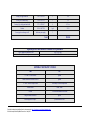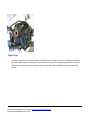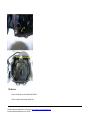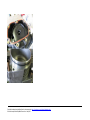
1
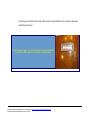
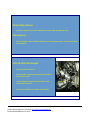
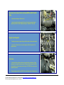
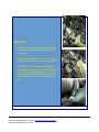
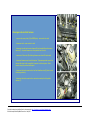
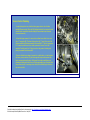
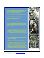
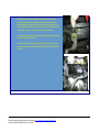
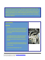
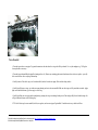
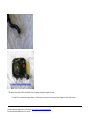
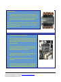
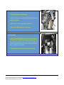
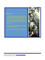
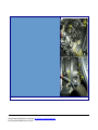
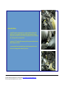
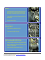
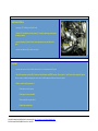
BMW 540i (E39, pre-VANOS) Maintenance:
- Intake System Gaskets and seals
- Valley pan
Breathing new life into your M62's leaky intake system, and fixing that nagging
valley pan coolant leak.
BACKGROUND
At around 82k miles my engine was clearly showing signs of minor air leaks in the intake system: rough idle when cold,
occasional miss at idle, periodic extended cranking times during starting, etc. Additionally, a BMW tech pointed out that
my valley pan seal was leaking a small amount of coolant, a common occurence on these motors.
There is some good news here: these two problems, leaky intake seals/gaskets and seeping valley pan, appear to have
nothing in common except, perhaps, for mileage. However, even if you're only trying to fix one, it's an easy task to take
care of the other on a pre-emptive basis while you're in there. In the case of the intake manifold, the only additional work is
R&R of the water manifold/plumbing and the valley pan. Total additional cost is around $50, a little more if you replace
the two hoses that attach to the manifold. Conversely, if you're after the valley pan in the first place, the manifold
gaskets/seals come along "for free."
I reviewed the BMW TIS documents and decided this would be a fairly straightforward procedure: no special tools
required, and less than a day's work. So I headed over to the dealer with parts list in hand.
Originally developed and published here by unknown author: http://members.cox.net/rlacm/IntakeIndex.htm
Recovered and published by BMW-Planet.com – May 2012
Note that a good majority of the required parts had to be special ordered, so plan your time accordingly. The entire job
took me just over six hours and included taking numerous photos for this writeup and a trip to the dealer since I hadn't
planned on the valley pan heat shield being too brittle to swap to the new pan. Additionally, I made several stupid mistakes
(hey, I had pneumonia when I did this work, so cut me some slack, ok?) which are noted in the text by "Dork Alert!".
Together these cost me at least 30-45 minutes, so I'm sure the job could be done in less than five hours if you were really in
a hurry.
Just to keep things fair, I've got many years experience as a shadetree mechanic, so it's difficult to say with certainty the
skill level required to complete this job. However, there are no particularly significant skills required to perform the work.
Look thru the information provided here and determine if your own experience level is appropriate for the task. I followed
the BMW TIS procedures verbatim, and the job went very smoothly with only minor surprises.
DO YOU NEED TO PERFORM THESE TASKS?
Valley Pan: Determining whether your valley pan is leaking or not is pretty easy. Does your car inexplicably lose small
amounts of coolant over time, yet you are unable to find the source of the leak after carefully checking all the usual
suspects? Simply remove the engine cover and, using a flashlight, look carefully behind the intake manifold down at the
engine block. Locate the water manifold which bolts to the back of the block for reference (two heater hoses attach to it),
then look forward an inch or two along the block/head interface on the passenger side until you find the valley pan, which
sits about an inch deeper in the engine block. If it's leaking, you'll see a buildup of cooked coolant in the corner(s) - no
matter where the pan is leaking, the coolant will settle back here over time and slowly bake from repeated heat cycles.
Note that the equivalent area on the driver's side of the block contains a drainage hole and the view is blocked by the engine
vent tube. You can also see the valley pan/block seam by looking down past the manifold at the front corners.
Intake System leaks: This one is a bit tougher to diagnose, unless you have a really bad leak. Rough idle on cold mornings
is common, along with a subtle bog when increasing throttle setting. I was also experiencing very subtle "hiccups" usually
when idling at a red light - the engine would just sort of skip a beat then resume running smoothly. Finally, my motor was
starting a bit more slowly at times than normal - by this I do not mean the starter was turning the engine over slowly - but
that the engine, instead of catching within one second of turning the key, would sometimes take 2 or 3. Nothing really
drastic - just when it happened, it would give me pause. If you suspect a leak, you can sometimes prove one by carefully
spraying appropriate liquid (Berryman's, etc.) on the suspect seal with the engine running. If you find a leak, the liquid will
Originally developed and published here by unknown author: http://members.cox.net/rlacm/IntakeIndex.htm
Recovered and published by BMW-Planet.com – May 2012
momentarily seal it and the RPM will increase for a short time. Note this is not a guaranteed method, and you can make a
mess of your paint if you get the spray on the wrong areas.
The information provided here is supplemental and is not intended to be used as a sole guide when performing the tasks
described. By providing this information I accept no responsibility whatsoever for your safety or the success of your work.
You are responsible for ensuring your safety and the proper use of all tools, jacks, supports, etc., proper care when handling
flammable liquids, and for the proper installation and assembly of components. Failure to do so can result in damage to your
vehicle and/or serious injury or worse to your person.
Originally developed and published here by unknown author: http://members.cox.net/rlacm/IntakeIndex.htm
Recovered and published by BMW-Planet.com – May 2012
On this page you'll find all the parts (with prices!) that I replaced during this job. Additionally, I've included lists of
special BMW-supplied tools, and general tools I used. Be sure to read the section following these tables...
REQUIRED PARTS
These parts should be good for all model year E39 540/6s with build dates from 6/96 to 9/98, but you should
verify with your parts department when ordering.
Prices current as of January 2005
Description
Part Number
Quantity
Price
Screw, throttle body to intake manifold
11-14-1-460-752
3
0.31 ea.
Cover, valley pan heat shield
11-14-1-736-106
1
12.75
Cap w/ Seal (valley pan)
11-14-1-742-042
1
41.40
Profile Gasket, vent pipe rear seal
11-15-1-702-291
1
6.88
O-Ring, vent tube rear seal
11-15-1-736-140
1
3.80
O-Ring, vent tube front seal
11-15-1-747-978
1
4.44
O-Ring, water pipe seal
11-53-1-710-048
2
2.40 ea.
O-Ring, water pipe seal
11-53-1-710-055
2
1.22 ea.
Gasket, Asbestos-free, water manifold
11-53-1-731-833
2
2.20 ea.
Profile Gasket, intake manifold-head
11-61-1-433-328
4
16.33 ea.
Blind Plug, brake booster hose
11-61-1-704-792
1
3.30
Profile Gasket, intake manifold front seal
11-61-1-729-727
1
7.02
Profile Gasket, intake manifold rear seal
11-61-1-729-728
1
7.02
Spacer, intake manifold mount
11-61-1-736-648
10
5.84 ea.
Originally developed and published here by unknown author: http://members.cox.net/rlacm/IntakeIndex.htm
Recovered and published by BMW-Planet.com – May 2012
O-Ring, vent pipe front seal
11-61-1-745-195
1
3.05
O-Ring, ASC throttle body
13-54-1-747-475
1
2.75
Covering Cap, valley pan heat shield
13-71-1-741-097
4
0.21 ea.
Coolant
82-14-1-467-704
1 gal.
25.30
Screw-type hose clamps, small
local auto parts supply
3
Total
$254.84
Optional parts which should be evaluated for replacement
Hose, engine inlet and water valve
Hose, radiator and engine return
64-21-8-391-005
64-21-8-391-013
GENERAL MECHANICS TOOLS
Tool
Use
1/2" and 1/4" drive ratchets
general
Various extensions for each size drive
general
1/2" drive "clicker" torque wrench
re-assembly of critical components
Metric sockets
11mm, 10mm
Torx Bit
T-30 for intake manifold cover bolts
Long flat-blade screwdriver
pry bar
Silicon spray lube or equiv.
pre-lubricate new seals
Originally developed and published here by unknown author: http://members.cox.net/rlacm/IntakeIndex.htm
Recovered and published by BMW-Planet.com – May 2012
Loc-Tite or equivalent (I always use the blue stuff)
various bolts/nuts (see text)
A word about the prices
I bought most of these parts "on a whim" while at San Diego BMW - my regular dealer is Cunningham. I did not
research the prices, since the total amount isn't very high. However, after seeing that I was charged $25 for a gallon of
coolant, and knowing that I paid around half that the last time I purchased coolant at Cunningham, I suspect I may have
been suckered. I've given SD-BMW several chances, and this will likely be the last time I spend any money there.
Caveat emptor.
The attached procedures are copyright BMWAG. I have not asked for permission to post these procedures: if BMW asks
me to remove them, I will.
As mentioned previously, I followed the BMW TIS procedures verbatim, and this worked very well for me. On this page
I have separated the tasks into two major headings, Disassembly and Assembly. Within each major heading are subtasks. Finally, within each subtask you will find links to each pertinent TIS procedure (all TIS procedures are in PDF
format). Detailed notes and photographs appear elsewhere. Note that some procedures call others from within the
procedure, so that you only perform a certain number of steps in one before moving to another. The list below follows
this calling procedure, and therefore contains duplicate links to the same procedure. The steps to be followed for a given
link in the list are noted at the end of each link.
Also note that for reassembly, the same procedures are followed in reverse. This is again noted in each link. The first
time a procedure is listed, its full TIS document number is shown: subsequent listings omit this information.
Originally developed and published here by unknown author: http://members.cox.net/rlacm/IntakeIndex.htm
Recovered and published by BMW-Planet.com – May 2012
Main Task
Sub-Task
TIS Procedure or Notes
Battery, etc.
TIS 11 53 325 - Removing and Installing Coolant Manifold
TIS 12 00 - Instructions for Disconnecting and Connecting Battery
Disassembly
Intake Manifold
TIS 11 61 050 - Removing and Installing Intake Manifold, M62 (all steps)
Coolant Manifold and plumbing
Valley pan
Valley pan
Assembly
Coolant manifold and plumbing
TIS 11 53 325 - Removing and Installing Coolant Manifold
Intake manifold
TIS 11 61 050 - Removing and Installing Intake Manifold, M62
Coolant fill
Battery
TIS 12 00 - Instructions for Disconnecting and Connecting Battery
Coolant flush
Review work, test drive
I spent six hours on this job, which included several stupid mistakes and one trip to the dealer. Hopefully the information
here will allow you to perform this work in five hours or less.
TORQUE SPECIFICATIONS
The only BMW-specified torque specifications for the parts involved in this procedure is 22Nm for the intake manifold to
head mounting nuts. For all other assembly, rely on your experience and remember that you are working with aluminum
components. See the text for additional information.
Originally developed and published here by unknown author: http://members.cox.net/rlacm/IntakeIndex.htm
Recovered and published by BMW-Planet.com – May 2012
On this page we'll attend to all the items which need to be disassembled to allow removal of the intake
manifold and valley pan.
Most of the required parts... note that I didn't realize the heat shield would
be so brittle, so didn't have one on hand prior to beginning work.
Originally developed and published here by unknown author: http://members.cox.net/rlacm/IntakeIndex.htm
Recovered and published by BMW-Planet.com – May 2012
Disconnect battery positive lead.
- make sure your seats/mirrors are in their #1 saved position so you can return them after reapplication of power.
Remove engine cover.
- Note that I realized three of the four foam donuts that sit on the cover’s mounting pegs were gone - I later found them sitting down
on the intake manifold.
Remove Idle Control Valve if so equipped
- disconnect wire harness from valve (A)
- disconnect plumbing (at both ends) running between valve and intake flex
hose, move aside for now (B)
- carefully disengage (don’t break off mounting feet) rubber hose clamp
surrounding valve from bracket (C)
- rotate valve upward to disconnect from throttle body, set valve aside.
Originally developed and published here by unknown author: http://members.cox.net/rlacm/IntakeIndex.htm
Recovered and published by BMW-Planet.com – May 2012
Disconnect and remove flex line between MAF and ASC throttle
body.
- release hose clamps on both ends (A)
- reach underneath and disconnect flex hose from intake resonator box by
supporting resonator while steadily pulling up on underside of hose (B)
Engine Cover Supports
- Carefully disconnect red snap fitting at throttle cables (it will probably break)
- remove four 10mm bolts, two on each support (A). Don’t drop bolts. Set
supports aside
Fuel Lines
- remove fuel lines at driver’s side rear of engine block (four places). Grasp
hose portion and push toward connector. Using other hand, press black lock
ring toward hose, then release hose from pipe. CAUTION: fuel may be under
significant pressure.
- Using a baggie and zip tie on EACH of four fuel pipes, seal off pipes (two on
Originally developed and published here by unknown author: http://members.cox.net/rlacm/IntakeIndex.htm
Recovered and published by BMW-Planet.com – May 2012
intake manifold and two on fender well). Place removed hoses in a clean
environment - ie., inside a large ziplock bag.
Driver’s side electrical harness
- remove valve cover plate (A) - carefully pry up two small plastic covers to gain
access to mtg bolts. Remove 10mm bolts. Pry plate away from valve cover with
hands. Remove and set aside.
- disconnect coils (B). On each of four coils, lift silver-gold connector lock clip,
then disconnect harness connector from coil.
- disconnect circular knock sensor harness (C) (there may be two such
connectors on VANOS motors. Also on VANOS motors I think there is a
second cam position sensor harness).
- remove two 10mm nuts (D) attaching harness covering (black plastic
rectangular box) to head. Set nuts aside.
- disconnect electronic harness from rear-most injector (E) - working from
bottom of connector, press metal retaining clip upward to release.
- disconnect harness cover from fuel injectors. The driver’s side cover is
essentially one large connector, providing electrical connection to the front
three injectors on this side. Grasp the cover/box with both hands and pull
directly up and away from the injectors (straight away from the injectors, a 45
degree angle from the vertical) - try to disconnect the cover from all three
injectors at the same time. Be prepared for the release: stop pulling as soon as
Originally developed and published here by unknown author: http://members.cox.net/rlacm/IntakeIndex.htm
Recovered and published by BMW-Planet.com – May 2012
the cover comes free. Allow cover to simply lay on head at this point.
Originally developed and published here by unknown author: http://members.cox.net/rlacm/IntakeIndex.htm
Recovered and published by BMW-Planet.com – May 2012
Accelerator Cables
- move main throttle lever backward with one hand while disconnecting both
accelerator and cruise control cable ends from lever - the plastic retainers
unsnap forward (A).
- remove throttle cable bracket from front of throttle body - 2x T30 Torx bolts
(B). This way you don’t need to readjust the cable position when you’re done.
- move ASC throttle lever (C) (on underside of secondary throttle body)
backward (clockwise looking down) to create slack in the ASC cable. Remove
the cable from the lever by unsnapping barrel end from lever and threading
cable thru slot. Pull ASC cable from mounting lug (D) on lower-right side of
secondary throttle body. You do not need to remove any more of the ASC
cable.
Originally developed and published here by unknown author: http://members.cox.net/rlacm/IntakeIndex.htm
Recovered and published by BMW-Planet.com – May 2012
Passenger side electrical harness
- remove valve cover plate (A) (the BMW plate) - same as driver’s side.
- disconnect coils - same as driver’s side.
- disconnect circular knock sensor harness (B) and crankshaft position sensor
harness (C) - lay each harness out of way toward front of motor.
- remove two 10mm nuts (D) attaching harness cover head. Set nuts aside.
- disconnect harness cover from fuel injectors. The passenger side cover is the
same as the driver’s side except that it connects to all four injectors. Allow
cover to simply lay on head at this point.
- disconnect electrical connector from fuel tank breather valve (E) (driver’s side
front of engine block)
- disconnect electrical connector from main and secondary throttle position
sensors (F).
Originally developed and published here by unknown author: http://members.cox.net/rlacm/IntakeIndex.htm
Recovered and published by BMW-Planet.com – May 2012
Vacuum Control Plumbing
- locate black pipe that runs front/back along upper driver’s side of intake
manifold. Remove single 10mm bolt (A) holding bracket at front-center of intake
manifold (note: rear bracket should already be loose when driver’s harness
cover was removed).
- follow black pipe rearward - it connects to a rubber hose, which in turn runs
into a ‘T’ connector (B). The hose that runs from this ‘T’ over to the rear of the
intake manifold must be disconnected at the manifold (C). This is a large pressfit ‘L’ connector which runs into a rubber grommet in the rear face of the
manifold. Carefully work the ‘L’ fitting loose from the grommet, twisting and
pulling it rearward from the manifold.
- Return to the black pipe where it connects to a rubber hose - cut and remove
the factory crimp connector (D) (don’t damage the hose) and disconnect the
black vacuum pipe from the hose. At this point the intake manifold vacuum
plumbing is disconnected from the car. During reassembly you will replace this
crimp connector with a screw-type hose clamp. Allow the black pipe to rest on
the intake manifold.
Originally developed and published here by unknown author: http://members.cox.net/rlacm/IntakeIndex.htm
Recovered and published by BMW-Planet.com – May 2012
Engine Vent Tube
- PITA Alert! The vent tube is located under the intake manifold (dotted lines in
photo), runs along the driver’s side head/block, and connects the block to the
intake manifold. This tube must be disconnected from the intake manifold prior
to the manifold’s removal.
- Remove the driver’s side air duct between the cabin air filter box and firewall at the filter box, release the retainer strap, then rotate the duct 45 degrees
counterclockwise and pull forward away from the firewall. Set duct aside.
- The vent tube mounts to the intake manifold (A) via an o-ring sealed slip fit.
The tube is retained by a spring clip (B), which snaps around the tube (C) and
clips over the manifold’s fitting (A). This clip is accessed at the driver’s side rear
of the intake manifold, down low. Using a small screwdriver, gently pry this clip
up away from the tube. If the clip slides forward on the tube under the manifold,
don’t worry - you’ll retrieve it later. If it falls off down into the motor, get it now
before you forget.
- Now slide the vent tube (C) forward off the connector fitting - it will probably
be stuck, so judicious use of a large screwdriver to help pry it away may be
called for. Work slowly and don’t break anything. Slide the tube all the way
forward until you see that it is completely disconnected from the fitting.
Here's where we'll actually remove the intake manifold, water manifold and plumbing and, finally, the valley
pan.
Originally developed and published here by unknown author: http://members.cox.net/rlacm/IntakeIndex.htm
Recovered and published by BMW-Planet.com – May 2012
Intake Manifold
- Find the vacuum line that runs from the fuel tank breather valve (A) (pete's T) under
throttle body and over to left-lower corner of throttle body. Disconnect this line
(cut/remove factory crimp connector) at the throttle body (B).
- There are ten 11mm nuts (C), five per side, retaining the manifold. Remove each
one, one at a time, being careful not to drop them down into motor.
- Remove each of ten mounting spacers from studs (C).
- Gently pry manifold up away from block just enough to ensure any seal is broken.
- PITA Alert! The engine wiring harnesses and black boxes make it difficult to remove
the manifold, however I did not want to disconnect all those wires, so I essentially slid
the manifold/throttle bodies forward out from underneath the harnesses. This is done
in two or three stages, as follows:
1. Locate the point at which the passenger side harness enters the firewall (D) (via
the flexible ducting). Lift the weather seal running along the top of the firewall up
away from this point, exposing the duct retainer. Pull this retainer straight up and
out, and set aside. Now raise the duct up in the firewall "slot" as much as possible
- maybe an inch or two. This allows additional clearance at the rear of the intake
manifold, without which you would not be able to remove it.
2. "Fold" the driver’s harness and box forward toward the fan. This again provides
clearance at the rear of the manifold.
3. BE CAREFUL, WORK SLOWLY, WATCH FOR WIRE HARNESSES, etc.
NOTE: you will be removing the intake manifold, throttle body, secondary throttle
body, fuel pipe/injectors, vacuum pipe and forward hoses/Tee all as a single
assembly. Grasp the manifold/throttle bodies and attempt to lift it off the block raise it as far as you can until you encounter obstructions - note what they are and
if possible, move them. You will eventually be able to lift the manifold up high
enough to allow moving it forward an inch or so, resting it on the mounting studs.
Originally developed and published here by unknown author: http://members.cox.net/rlacm/IntakeIndex.htm
Recovered and published by BMW-Planet.com – May 2012
4. Now "unfold" the driver’s wire harness/box, laying back in its original position.
Carefully continue to work the manifold forward until it is clear of the wiring
harnesses and remove from vehicle. Work slowly and ensure the manifold
assembly really is disconnected - there is nothing worse than thinking a part is
free, moving it away from the car only to have a wire or tube catch and yank it out
of your hands, causing it to crash down on your bodywork. Set aside.
5. Immediately wedge clean rags or paper towels into each intake port (E), doing
your best to keep foreign matter out.
6. Remove vent tube by sliding rearward off fitting in block. Remove o-ring from
front end of vent tube and discard. REMOVE RETAINER CLIP FROM TUBE. Set
both aside.
Originally developed and published here by unknown author: http://members.cox.net/rlacm/IntakeIndex.htm
Recovered and published by BMW-Planet.com – May 2012
At this point, inspect the area around the valley pan - that black plate is a plastic heat shield which snaps to the pan.
The retainer clips will undoubtedly break when unsnapped, so plan on replacing the shield if you replace the pan. If you
see any trace of (dried) coolant in this area, replace the valley pan. In fact, given that the plate and heat shield only cost
about $50, you should replace them as a preventative measure while the manifold is off. The seal on my original pan
was a traditional flat gasket while the new one uses an o-ring (apparently this is a common failure mode and has been
addressed with an updated part).
VALLEY PAN REMOVAL
Water Manifold
- Heater hoses. There are two heater hoses (A) which must be disconnected at the
manifold. Now would be a perfect time to replace these hoses, depending on the
condition of yours. The long one historically fails with a pinhole right at the top of the
first bend. Remove both hoses from the manifold (coolant will escape when these
hoses are removed).
- The manifold (B) is bolted to the block via six (three per side) 10mm bolts. These
bolts run straight forward into the rear face of the block. Using a combination of
deep and standard 1/4" drive sockets, along with a short (1") extension on the
passenger side, remove all six bolts. More coolant will escape once the manifold
seal is broken.
- The two water pipes which run between the water pump and the manifold (C) use
o-ring seals at each end. Work the pipes off the manifold, and remove the manifold
from the vehicle: set aside.
- Work the two pipes out of the water pump housing: set aside.
Originally developed and published here by unknown author: http://members.cox.net/rlacm/IntakeIndex.htm
Recovered and published by BMW-Planet.com – May 2012
Valley Pan
- Clean up as much gunk from the area around the valley pan and intake ports as
possible. The intent is to avoid contaminating the remaining coolant which will be
exposed once the valley pan is removed. Of course, it is imperative to keep debris
from entering the intake ports during this operation. A small screwdriver is useful for
loosening the gunk, followed up with a shop vac (don’t hoover up the paper towels
from the intake ports). I used a brush attachment on my shop vac, which did a good
job of getting rid of the dirt which had accumulated on the sides of the heads. If it is
really dirty, a solution of water and laundry detergent may be sprayed everywhere,
followed by toothbrush and hose to rinse it off (obviously you don’t want to get water
in the intake ports - just use low pressure to rinse the mess out the back of the
block.
- Once everything is clean and dry, remove the twenty 10mm bolts (A) attaching the
valley pan to the block. Dork Alert! Note that beneath the black heat shield, the
valley pan can hold a large amount of water (if you used water during the cleanup
process). Don’t allow this water to drain out into the block when removing the pan.
- Gently pry (use small screwdriver as necessary) the valley pan to loosen its seal.
Once loose, work the pan/shield up past the knock sensors (B), and remove the
valley pan.
Originally developed and published here by unknown author: http://members.cox.net/rlacm/IntakeIndex.htm
Recovered and published by BMW-Planet.com – May 2012
VALLEY PAN INSTALLATION
Valley Pan
- Spend a bit more time cleaning up the area, keeping debris from entering the coolant in the block (and the intake ports). Carefully clean the valley pan sealing
surface - use a light solvent (eg., WD40) on a paper towel to wipe clean. I also ran a piece of 2,000-grit sandpaper over this surface as insurance. The surface
should be nice and shiny when suitably clean.
- Dork Alert! Attach the new heat shield to the new valley pan PRIOR to installation of the pan: failure to do so will require removal of the pan, as the shield will
not fit past the knock sensors if the valley pan is already installed. Take care when handling the new valley pan not to disturb the attached seal.
- Clean all twenty bolts. Apply a small drop of threadlok to each bolt, near the bottom.
- Install valley pan/heat shield - it only fits one way. Loosely install two bolts, one on each side, in the middle of the block. Loosely install two bolts, one on each
end, to align pan. Once you are sure the pan is aligned, snug but do not tighten the first two bolts.
- Install the remaining sixteen bolts, working from the center outward, snugging each bolt, but do not tighten. When all twenty bolts are snug, tighten each, again
working from the center outward.
Originally developed and published here by unknown author: http://members.cox.net/rlacm/IntakeIndex.htm
Recovered and published by BMW-Planet.com – May 2012
Water Manifold
- Clean and inspect the two water pipes. Pay particular attention to the ends where the o-ring seals will be positioned. Use very fine sandpaper (eg., 2,000 grit) to
clean up the ends as necessary.
- Clean and inspect the manifold and engine block mating surfaces (A). Remove any remaining gasket material and ensure these surfaces are spotless - you really
don’t want a leak here after everything is buttoned up.
- Carefully remove all four old o-rings - two from the manifold, and two from the water pump. Don’t nick the sealing surfaces.
- Carefully install four new o-rings - two in the water pump housing, and two in the water manifold. Make sure the o-rings are fully seated and not twisted. Apply a
light coat of suitable lubricant (eg., silicon spray) to each o-ring.
- Carefully install the two water pipes into the pump housing, ensuring the o-ring is not damaged in the process. Push each pipe fully forward in the housing - this
will give additional clearance in the following step.
- PITA Alert! In this step, the water manifold, six bolts, two gaskets, and two water pipes all get installed. I found the easiest way to do this as follows:
Originally developed and published here by unknown author: http://members.cox.net/rlacm/IntakeIndex.htm
Recovered and published by BMW-Planet.com – May 2012
1. Insert one bolt into the driver’s side upper mounting hole of the manifold. Install one gasket onto this bolt - gasket only fits one way (hold manifold such
that bolt doesn’t slide out, and gasket doesn’t fall off). Position manifold on engine block and start threads of first bolt - get it threaded maybe 3-4 turns. Be
careful not to let the gasket fall off or the bolt slide out - if this happens you’ll spend ten minutes fishing it off the top of the header. You want as much play
in the manifold as possible without risking pulling the bolt out of the hole.
2. Repeat this process with one bolt and remaining gasket on the passenger side. Note that you SHOULD be able to get the bolt threaded while still leaving
enough slop in the manifold-to-block clearance to allow positioning of the water pipes in the manifold. Make sure you put the gasket on correctly. At this
point your work should look as shown at B.
3. Now draw the manifold forward toward the block with one hand while guiding the tubes into their respective sockets with your other - when the pipes hit
the o-rings they will hold themselves in place. Twist each pipe slightly to ensure proper seating - don’t pull them backward or they may back out of the water
pump housing.
4. Making certain the gasket is correctly positioned, insert a second bolt into the manifold on the driver’s side and snug it up - do not tighten yet. Repeat this
procedure for the passenger side.
5. Finally, insert the third bolt into the driver’s side of the manifold, snugging both it and the first bolt. Repeat for passenger side.
6. Finally, tighten all six water manifold bolts evenly. Once the manifold is tight, grasp and twist each pipe to center it between the water pump and
manifold.
7. Once everything is happy, use a flashlight to check one last time that the gaskets are correctly aligned. Now stand up straight and stretch out your aching
back muscles.
- Reinstall both water hoses, adjusting hose clamps so that the screws are accessible from above after everything is reinstalled (ie., plan for the worst - it IS possible
to replace these hoses with the intake manifold installed).
Originally developed and published here by unknown author: http://members.cox.net/rlacm/IntakeIndex.htm
Recovered and published by BMW-Planet.com – May 2012
Originally developed and published here by unknown author: http://members.cox.net/rlacm/IntakeIndex.htm
Recovered and published by BMW-Planet.com – May 2012
Originally developed and published here by unknown author: http://members.cox.net/rlacm/IntakeIndex.htm
Recovered and published by BMW-Planet.com – May 2012
INTAKE MANIFOLD DISASSEMBLY AND SEAL/GASKET REPLACEMENT
Vacuum Plumbing
- Locate the black vacuum pipe/hose assembly which came away from the car with the intake manifold. Follow the hose to where it connects to the lower right
corner of the primary throttle body (A). Remove this hose (cut/remove factory crimp connector) and separate the vacuum plumbing from the manifold.
Secondary Throttle Body Disassembly
- Remove three T-30 TORX bolts hold secondary throttle body to main throttle body (B).
- Gently break seal and remove throttle body using a twisting motion
Throttle Body Disassembly
- Remove six T-30 TORX bolts (C) holding throttle body to intake manifold. PITA Alert! the lower three bolts (or more) will likely be stuck, and the heads will
strip making traditional removal with the Torx tool impossible . If this occurs, use a small pair of vice grips to carefully break the bolt(s) loose, then remove with
the Torx tool.
- Gently break seal and remove throttle body from manifold.
Originally developed and published here by unknown author: http://members.cox.net/rlacm/IntakeIndex.htm
Recovered and published by BMW-Planet.com – May 2012
Rear Manifold Cover
- Remove vacuum hose (A) between fuel pipe and rear cover (leave attached to diaphragm on fuel pipe). Using a baggie and zip tie, seal off this hose (on fuel pipe
side).
- Remove seven T-30 Torx bolts (B) from rear cover.
- Carefully break the seal between rear cover and manifold. Pull rear cover back and off of manifold.
Originally developed and published here by unknown author: http://members.cox.net/rlacm/IntakeIndex.htm
Recovered and published by BMW-Planet.com – May 2012
Engine Vent Pipe
- The vent pipe runs up thru the center of the intake manifold, between the front and rear covers. It attaches to the rear cover via a rubber grommet, and clips into
the front of the manifold. Gently press this retaining clip (A) inward toward the center of the pipe to release, and push the pipe out thru the back of the manifold.
Note that this pipe is telescopic - it comprises two sections which join in the center and allow the pipe to expand slightly. This will become important during
reassembly.
Originally developed and published here by unknown author: http://members.cox.net/rlacm/IntakeIndex.htm
Recovered and published by BMW-Planet.com – May 2012
Miscellaneous
- Remove the front and rear seals from the Intake Manifold.
- Remove o-ring from front of primary throttle body.
Originally developed and published here by unknown author: http://members.cox.net/rlacm/IntakeIndex.htm
Recovered and published by BMW-Planet.com – May 2012
- Remove the o-ring from the front of the vent pipe.
- Remove black vent pipe seal (black) from inside center of rear cover (A).
- Remove vent tube seal (blue) from lower driver’s side corner of rear cover (B).
- Remove brake booster grommet (red/orange) from rear cover (C).
Originally developed and published here by unknown author: http://members.cox.net/rlacm/IntakeIndex.htm
Recovered and published by BMW-Planet.com – May 2012
Originally developed and published here by unknown author: http://members.cox.net/rlacm/IntakeIndex.htm
Recovered and published by BMW-Planet.com – May 2012
This completes disassembly of the intake manifold. Clean all components thoroughly, noting the following:
- Use Simple Green, water/laundry detergent mixture, or a mild automotive parts cleaner to loosen grime from all components. Rinse with fresh water.
Originally developed and published here by unknown author: http://members.cox.net/rlacm/IntakeIndex.htm
Recovered and published by BMW-Planet.com – May 2012
- Avoid getting water/cleaning solution in vent assembly on rear cover.
- Avoid getting injector nozzles in intake manifold ports wet (not a disaster if this occurs).
- Ensure all sealing surfaces are perfectly clean - especially the intake manifold runners and front/rear cover seal grooves.
- Dry all parts with forced air or lintless cloth/paper towels.
When all components are perfectly clean and dry, continue with reassembly.
Originally developed and published here by unknown author: http://members.cox.net/rlacm/IntakeIndex.htm
Recovered and published by BMW-Planet.com – May 2012
INTAKE MANIFOLD SUBASSEMBLY
Vent Tube
- Carefully install new o-ring into front of vent tube, apply light coat of lubricant to o-ring,
then install vent tube into engine block. Push tube all the way toward front of engine. Dork
Alert! Make sure spring clip is removed from tube - if you leave it on tube it will be virtually
impossible to retrieve it once intake manifold is installed.
Vent Pipe
- Carefully install new o-ring onto front end of vent pipe; lightly lubricate.
- Working from rear of intake manifold, insert vent pipe into receiver hole in front of
manifold, using alignment lug. Push pipe forward until retainer clip snaps into place. Ensure
rear end of pipe is correctly positioned in manifold.
Rear Manifold Cover
- Install new seal into rear face of intake manifold.
- Install new vent pipe seal into center inside face of rear cover. Lubricate.
- Install new o-ring onto vent tube fitting at lower-left corner of cover (blue). Lubricate.
- Install new booster grommet (red/orange) into rear cover. Lubricate.- Verify that vent pipe
remains correctly positioned in rear of manifold, and install rear cover onto manifold (7x T30 bolts).
Originally developed and published here by unknown author: http://members.cox.net/rlacm/IntakeIndex.htm
Recovered and published by BMW-Planet.com – May 2012
NOTE: refer to previous photo for locations of these seals.
- Working from the front of the intake manifold, reach into manifold and gently grasp rear
half of vent pipe. Push pipe backward (telescoping it slightly) onto rear cover seal, ensuring
pipe is completely seated at each end.
Primary Throttle Body
- Install new seal into front face of intake manifold - ensure seal is properly seated.
- Install primary throttle body to intake manifold using new bolts as necessary, tightening in
a star pattern (6x T-30 bolts) (C).
Secondary Throttle Body
- Install new o-ring onto front of primary throttle body: lightly lubricate.
- Install secondary throttle body (3x T-30 Torx bolts) (B).
- Dork Alert! Failure to complete this step will really piss you off later. Position black vacuum
control pipe onto manifold using front bracket and single nut (don’t tighten). Locate hose at
front (connected to T network) which was removed from nipple at lower-right corner of
primary throttle body. Reconnect to nipple (A) using new screw-type hose clamp,
positioning screw so that it faces up on right side of nipple.
Originally developed and published here by unknown author: http://members.cox.net/rlacm/IntakeIndex.htm
Recovered and published by BMW-Planet.com – May 2012
Intake Manifold Seals
- Turn manifold assembly upside down and install four new seals into mating grooves,
positioning each seal so that the section which connects the seals is on the outer edge of
the manifold. PITA Alert! During installation of the manifold these seals may fall out of their
grooves. Be sure they are correctly seated prior to final positioning of manifold.
At this point we’re ready to reinstall the intake manifold. Reinspect all work completed thus far, as
a final check. Pay attention to the engine block and sealing surfaces, and make sure all wiring
harnesses are positioned out of the way.
INTAKE MANIFOLD INSTALLATION
- Remove paper towels from intake ports in heads.
- Move driver’s side engine harness toward back of engine compartment, resting on
valve cover and firewall. Move passenger side harness as far rearward as possible.
Ensure knock sensor harnesses run forward along the bottom of the valley, draping
over front of engine block.
- Position intake manifold assembly onto motor, as far back as possible (A) until
interference with engine harnesses is encountered. Note in this photo how one of
the intake seals has dropped down out of its mounting groove.
- Now reposition driver’s side harness to the front of compartment, "folding" it back
forward. Reposition driver’s harness forward as much as possible.
- Now carefully work intake manifold rearward until you can lay it down over
mounting studs.
- Once the manifold is located on the mounting studs, use a suitable lever (B) (eg.,
ratchet wrench handle) to wedge the manifold up off the engine. Carefully ensure
all intake manifold seals are correctly positioned in their grooves. Do this
Originally developed and published here by unknown author: http://members.cox.net/rlacm/IntakeIndex.htm
Recovered and published by BMW-Planet.com – May 2012
both visually and by touch!
- Carefully lower manifold onto engine block/heads.
- Install ten new mounting spacers, repositioning manifold slightly and as necessary
to attain correct alignment.
- Install ten 10mm hex nuts onto mounting studs, snugging each.
- Torque each nut to 22Nm, working from the center outward.
Vent Tube Installation
- Position a large flat-blade screwdriver on front edge of vent tube (accessible at
front/lower/left corner of intake manifold). Using fingers of right hand, position vent
tube such that it is aligned with fitting on rear cover of manifold. Using left hand and
screwdriver, gently pry vent tube backward onto rear cover fitting. Ensure o-ring
seal is not damaged during this procedure.
- Snap spring retainer onto rear end of vent tube and over rear cover fitting.
Originally developed and published here by unknown author: http://members.cox.net/rlacm/IntakeIndex.htm
Recovered and published by BMW-Planet.com – May 2012
Vacuum Plumbing Installation
- PITA Alert! Access is difficult for this step. Pre-adjust a small screw-type hose
clamp and, using a pair of needle nose pliers, position clamp over nipple at lowerleft corner of primary throttle body (B, 1st photo pair) so that screw will be facing up
on the left side of nipple. Locate vacuum line from fuel tank breather valve (A, 1st
photo pair) (pete’s T) and working from under secondary throttle body, press hose
onto nipple and into hose clamp. Tighten clamp using second screwdriver to hold in
place as necessary.
- Reconnect hose from brake booster network to back end of black vacuum pipe
(D). Secure using new screw-type hose clamp.
- Insert ‘L’ connector on vacuum hose into grommet in rear intake manifold cover
(C).
Originally developed and published here by unknown author: http://members.cox.net/rlacm/IntakeIndex.htm
Recovered and published by BMW-Planet.com – May 2012
Originally developed and published here by unknown author: http://members.cox.net/rlacm/IntakeIndex.htm
Recovered and published by BMW-Planet.com – May 2012
Passenger side electrical harness Installation
- connect electrical connectors to main and secondary throttle position sensors (F).
- connect electrical connector to fuel tank breather valve (E) (driver’s side front of
engine block)
- connect harness cover to fuel injectors. Align each of the four connectors to the
injectors and firmly press the cover down using both hands.
- install two 10mm nuts and two washers (D), attaching harness cover head,
making sure cover is correctly aligned.
- connect circular knock sensor (B) and crankshaft position sensor (C) connectors
to passenger side cover, being careful to correctly route each harness.
- connect each of the four coils by lifting the locking plate and inserting the
connector down over the coil - ensure the lock plate is securely fastened.
- Install valve cover plate (2x 10mm bolts, A). Carefully install two small plastic
covering plates.
Originally developed and published here by unknown author: http://members.cox.net/rlacm/IntakeIndex.htm
Recovered and published by BMW-Planet.com – May 2012
Accelerator Cables
- Insert ASC cable into mounting lug (D) on secondary throttle body. Move ASC
throttle lever (C) (on underside of secondary throttle body) backward (clockwise
looking down). Feed cable thru slot in lever and snap barrel end into lever. Release
lever, ensuring cable is correctly positioned.
- remove two T-30 Torx bolts (B) from primary throttle body and install throttle cable
bracket, replacing Torx bolts.
- move main throttle lever backward with one hand while inserting throttle cables
into lever and snapping plastic retainers (A) into place.
Originally developed and published here by unknown author: http://members.cox.net/rlacm/IntakeIndex.htm
Recovered and published by BMW-Planet.com – May 2012
Driver’s side electrical harness
- connect electronic harness to rear-most fuel injector (E).
- connect harness cover to three foremost fuel injectors. Align each of the three
connectors to the injectors and firmly press the cover down using both hands.
- Install cover using two 10mm nuts and one washer (D) (front mounting post),
making sure to capture the rearward bracket of the black vacuum pipe’s rearward
bracket on the rear mounting post. Tighten nut at front vacuum pipe mounting
bracket.
- connect circular knock sensor harness (C).
- connect coils.
- Install valve cover plate using 2x 10mm bolts (A). Carefully install two small
plastic covering plates.
Originally developed and published here by unknown author: http://members.cox.net/rlacm/IntakeIndex.htm
Recovered and published by BMW-Planet.com – May 2012
Fuel Lines
- Remove baggies and zip ties from four fuel lines and from hose at left-rear of
fuel pipe. Install fuel lines (on my motor the ends of the hoses with the yellow
marks connected to the car-side of the fuel system, red marks to engine side).
- Connect rubber hose from end of fuel pipe to fitting on upper-left corner of rear
intake manifold cover.
- Reinstall driver’s side cabin air duct.
Engine Cover Supports
- Using four 10mm bolts (A), install engine cover supports.
- Carefully connect red snap fitting at throttle cables.
Intake Flex line between MAF and ASC throttle body.
- Position flex hose between secondary throttle body, MAF, and intake resonator
chamber. While supporting resonator, press connector (B) on bottom of flex hose
into resonator until it snaps into place.
- Position and secure both ends of flex hose with hose clamps (A).
Originally developed and published here by unknown author: http://members.cox.net/rlacm/IntakeIndex.htm
Recovered and published by BMW-Planet.com – May 2012
Idle Control Valve
- Insert grey ICV bushing into throttle body.
- Position ICV and rubber mounting clamp (C), carefully capturing mounting ears
of clamp in bracket.
- connect plumbing (B) (at both ends) running between valve and intake flex
hose.
- connect wire harness (A) to valve connector.
Coolant
- Loosen vent screw at top of radiator tank and in front of expansion tank fill pipe.
- Slowly fill expansion tank with 50/50 mixture of distilled water and BMW coolant. Allow coolant to "settle" and refill as required. Repeat
until no more air is heard escaping from vent screw. Install expansion tank cap but do not tighten.
- Perform careful visual inspection of:
- Water pipes at water pump
- Water pipes at water manifold
- Water manifold to engine block
- Heater hose connections
Originally developed and published here by unknown author: http://members.cox.net/rlacm/IntakeIndex.htm
Recovered and published by BMW-Planet.com – May 2012
Connect battery positive lead.
- After power is reapplied, turn key to RUN position but do not start engine.
- Store current seat/mirror settings to #1 position (#2 and #3 will be lost). Reset clock, calendar, and speed limit gong. Reinitialize sunroof.
Start Engine, Check for Leaks
- Start engine and allow to idle. Note that it may be difficult (eg., 5-10 seconds) to get motor running initially.
- Quickly observe motor, listening for vacuum leaks and looking for coolant leaks. CAUTION: the fan will hurt you if you forget it is running.
You do not want to run the motor too long yet, since you still need to purge the cooling system of air.
- Stop engine.
Assuming all is well, proceed to Cooling System Purge. Otherwise, correct problems as necessary.
Cooling System Purge
- Turn key to RUN but do not start engine.
- Close vent screw at top of radiator tank. Make sure expansion tank cap is on but not tight.
- Set cabin temperature controls (both sides) to max temperature.
Originally developed and published here by unknown author: http://members.cox.net/rlacm/IntakeIndex.htm
Recovered and published by BMW-Planet.com – May 2012
- Set fan to minimum speed (not "off").
- Start engine, and immediately:
- quickly rev engine to ~ 4,500RPM and immediately allow return to idle,
- repeat 2x.
- Stop engine.
- Observe coolant level, adding 50/50 mix as required. Repeat engine startup/rev/stop/coolant level check procedure until no more coolant
is needed.
- Tighten expansion tank cap and reset cabin temperature controls to desired settings.
With engine OFF, complete final visual inspection of all work. Once satisfied, reinstall engine cover.
GOOD LUCK, and HAVE FUN!!!
Originally developed and published here by unknown author: http://members.cox.net/rlacm/IntakeIndex.htm
Recovered and published by BMW-Planet.com – May 2012