1
Notice for Users in the USA
FCC Statement
WARNING - FCC Regulations state that any unauthorized changes or modifications
to this equipment not expressly approved by the manufacturer could void the user’s
authority to operate this equipment.
Note: This equipment has been tested and found to comply with the limits for a Class
B digital device pursuant to Part 15 of the FCC Rules.
These limits are designed to provide reasonable protection against harmful
interference in a residential installation. This equipment generates, uses and can
radiate radio frequency energy and, if not installed and used in accordance with the
instructions, may cause harmful interference to radio communications. However,
there is no guarantee that interference will not occur in a particular installation. If
this equipment does cause harmful interference to radio or television reception,
which can be determined by turning the equipment off and on, the user is encouraged
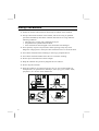
to try to correct the interference by one or more of the following measures:
•
•
•
•
Reorient or relocate the receiving antenna.
Increase the distance between the equipment and receiver.
Connect the equipment into an outlet on a circuit different from that to which the
receiver is connected.
Consult the dealer or an experienced radio / TV technician for help.
A shielded I/F cable is required to insure compliance with FCC regulation for Class
B computing equipment.
* As an Energy Star Partner, SHARP has determined that this product meets the
Energy Star guidelines for energy efficiency.
i
About Modem
This equipment PC-9080 complies with Part 68 of FCC rules. On the bottom of this
equipment is a label that contains, among other information, the FCC registration
number and ringer equivalence number (REN) for this equipment. If requested, this
information must be provided to the telephone company.
The modem jack of this equipment complies with Sub-part F of Part 68 of FCC
rules.
The REN is used to determine the quantity of devices which may be connected to the
telephone line. Excessive RENs on the telephone line may result in the devices not
ringing in response to an incoming call. In most, but not all areas, the sum of the
RENs should not exceed five (5.0). To be certain of the number of devices that may
be connected to the line, as determined by the total RENs contact the telephone
company to determine the maximum REN for the calling areas.
If the terminal equipment causes harm to the telephone network, the telephone
company will notify you in advance that temporary discontinuance of service may be
required. But if advance notice isn't practical, the telephone company will notify the
customer as soon as possible. Also, you will be advised of your right to file a
compliant with the FCC if you believe it necessary.
The telephone company may mark changes in its facilities, equipment, operations, or
procedures that could affect the operation of the equipment. If this happens, the
telephone company will provide advance notice in order for you to make the
necessary modifications in order to maintain uninterrupted service.
It trouble is experience with this equipment, please contact Sharp Electronics Corp.
for repair and (or) warranty information (Refer to the end of this section). If the
trouble is causing harm to the telephone network, the telephone company may
request you remove the equipment from the network until the problem is resolved.
The equipment cannot be used on public coin service provided by the telephone
company. Connection to Party Line Service is subject to state tariffs. (Contact the
state public utility commission, public service commission or corporation
commission for information.)
ii
The Telephone Consumer Protection Act of 1991 marks it unlawful for any person to
use a computer or other electronic device, including fax machines, to send any
message unless such message clearly contains in a margin at the top or bottom of
each transmitted page or on the first page of the transmission, the date and time it is
sent and an identification of the business or other entity, or other individual sending
the message and the telephone number of the sending machine or such business,
other entity, or individual. (The telephone number provided may not be a 900
number or any other number for which charges exceed local or long-distance
transmission charges.) To program this information, refer to the manual of the
communication software.
CAUTION
Danger of explosion if battery is incorrectly replaced. Replace only with the same or
equivalent type recommended by the manufacturer. Discard used batteries according
to the manufacturer's instructions.
Copyright
It is the intent of Sharp that this product be used in full compliance with the
copyright laws of the United States and that prior permission be obtained from
copyright owners whenever necessary.
Product Information and Customer Assistance
For Product Information and Customer Assistance:
Call: 1-800-BE-SHARP (237-4277)
Sharp Electonics Corp.
Sharp Plaza
Mahwah, NJ
07430
iii
Notice for Users in Canada
About Modem
The Load Number of your modem is 6.
The Industry Canada label identifies certified equipment.
This certification means that the equipment meet certain telecommunications
network protective, operational and safety requirements. The department does not
guarantee the equipment will operate to the user's satisfaction.
Before installing this equipment, users should ensure that it is permissible to be
connected to the facilites of the local telecommunications company.
The equipment must also be installed using an acceptable method of connection. In
some cases, the company's inside writing associated with a single line individual
service may be extended by means of a certified connector assembly (telephone
extension cord). The customer should be aware that compliance with the above
conditions may not prevent degradation of service in some situations.
Repairs to certified equipment should be made by an authorized Canadian
maintenance facility designated by the supplier. Any repairs or alterations made by
the user to this equipment, or equipment malfunctions, may give the
telecommunications company cause to request the user to disconnect the equipment.
Users should ensure for their own protection that the electrical ground connections
of the power utility, telephone lines and internal metallic water pipe system, if
present, are connected together. This precaution may be particularly important in
rural areas.
CAUTION Users should not attempt to make such connections themselves, but
should contact the approprlate electric inspection authrity, or electrician, as
appropriate.
iv
“The Load Number (LN) assigned to each terminal device denotes the percentage
of the total load to be connected to a telephone loop which is used by the device. To
prevent overloading, the termination on a loop may consist of any combination of
devise subject only to the requirement that the total of the Load Numbers of all the
devices does not exceed 100.”
This digital apparatus does not exceed the Class A Limits for radio noise emissions
from digital apparatus as set out in the Radio Interference Regulation of the
Canadian Department to Communications.
v
Notice for Users in Australia
Service Inquiries
Please contact your dealer for service if required or contact Sharp Corporation of
Australia on 1-800-807820 (free call) for referral to your nearest Sharp authorised
Service Centre. Details can be found on the warranty card inserted with the
documentation.
CAUTION
Danger of explosion if battery is incorrectly replaced. Replace only with the same or
equivalent type recommended by the manufacturer. Do not dispose of large
quantities of used Lithium batteries at the same time.
Copyright
Copyright may exist in material you wish to record. Copying or broadcasting such
material without permission of the relevant licensees or owners of the copyright is
prohibited by law.
SHARP is not in a position to authorise the copying or broadcasting of copyright
materials and nothing in this OPERATION MANUAL should be implied as giving
that authority.
vi
Notice for Users in the UK
IMPORTANT
The wires in this mains lead are coloured in accordance with the following code:
BLUE:
Neutral
BROWN: Live
As the colours of the wires in the mains lead of this apparatus may not
correspond with the coloured markings identifying the terminals in your plug
proceed as follows.
The wire which is coloured BLUE must be connected to the terminal which is
marked with the letter N or coloured black.
The wire which is coloured BROWN must be connected to the terminal which
is marked with the letter L or coloured red.
This apparatus must be protected by a 3A fuse in the mains plug or
distribution board.
“WARNING: THIS APPARATUS MUST BE EARTHED”
This apparatus is approved under approval number NS/G 1234/J/100003 for indirect
connection to the public telecommunication system in the United Kingdom.
Copyright
Recording and playback of any material may require consent, which SHARP is
unable to give. Please refer particularly to the provisions of the Copyright Act 1956,
the Dramatic and Musical Performers Protection Act 1958, the Performers
Protection Acts 1963 and 1972 and to any subsequent statutory enactments and
orders.
vii
Notice for Users in Europe
This equipment complies with the requirements of Directives
89/336/EEC and 73/23/EEC as amended by 93/68/EEC.
Dieses Gerät entspricht den Anforderungen der EG-Richtlinien
89/336/EWG und 73/23/EWG mit Änderung 93/68/EWG.
Ce matériel répond aux exigences contenues dans les directives
89/336/CEE et 73/23/CEE modifiées par la directive 93/68/CEE.
Dit apparaat voldoet aan de eisen van de richtlijnen 89/336/EEG en
73/23/EEG, gewijzigd door 93/68/EEG.
Dette udstyr overholder kravene i direktiv nr. 89/336/EEC og
73/23/EEC med tillæg nr. 93/68/EEC.
Quest' apparecchio è conforme ai requisiti delle direttive 89/336/EEC e
73/23/EEC, come emendata dalla direttiva 93/68/EEC.
´
´
´
´
Η εγκατασταση
αυτη ´ανταποκρινεται
στιζ απαιτησειζ
των οδηγιων τηζ
´
Ευρωπαïκηζ Ενωσηζ 89/336/EOK κατ 73/23/EOK, óπωζ οι κανονισµοι
´
´
´
αυτοι συµπληρωθηκαν
απó την
οδηγια 93/68/EOK.´
Este equipamento obedece às exigências das directivas 89/336/CEE e
73/23/CEE, na sua versão corrigida pela directiva 93/68/CEE.
Este aparato satisface las exigencias de las Directivas 89/336/CEE y
73/23/CEE, modificadas por medio de la 93/68/CEE.
Denna utrustning uppfyller kraven enligt riktlinjerna 89/336/EEC och
73/23/EEC så som komplette ras av 93/68/EEC.
Dette produktet oppfyller betingelsene i direktivene 89/336/EEC og
73/23/EEC i endringen 93/68/EEC.
Tämä laite täyttää direktiivien 89/336/EEC ja 73/23/EEC vaatimukset,
joita on muutettu direktiivillä 93/68/EEC.
viii
CAUTION:
TO PREVENT ELECTRICAL SHOCK, DISCONNECT THE AC CORD AND
THE BATTERY BEFORE SERVICING.
CAUTION:
FOR A COMPLETE ELECTRICAL DISCONNECTION, PULL OUT THE MAIN
PLUG AND THE BATTERY.
VORSICHT:
UM DIE STROMZUFUHR VOLLSTÄNDIG ZU UNTERBRECHEN, DEN
NETZSTECKER HERAUSZIEHEN UND DIE BATTERIE ÈNTFERNEN.
ATTENTION:
POUR UN ARRET TOTAL DU SYSTEME, DECONNECTEZ LE FIL DE LA
BATTERIE.
VARNING:
FÖR TOTAL ELEKTRISK URKOPPLING, KOPPLA UR KONTAKTEN OCH
TA UR BATTERIET.
PRECAUCION:
PARA UNA COMPLETA DESCONEXION ELECTRICA DESENCHUFE LA
CLAVIJA DE LA RED Y LA BATERIA.
ix
Safety Precautions
•
•
•
•
•
•
•
•
•
x
Follow all cautions and instructions which may be marked on the notebook.
Except as described elsewhere in this manual, refer all servicing to qualified
personnel. Immediately shut off the notebook and refer for servicing under the
following conditions:
• when the power cord or plug is damaged or frayed
• if liquid has been spilled on the notebook
• if the notebook has been dropped or the cabinet has been damaged
Never push any objects of any kind into cabinet openings. They may touch
dangerous voltage points or short parts that could result in fire or electrical shock.
Turn off the notebook before installing or removing a peripheral device.
Turn off the notebook and disconnect the AC cord before cleaning.
Do not expose the notebook to direct sunlight.
Keep the notebook away from any magnetic devices and TVs.
Do not drop the notebook.
Since this product is not waterproof, do not use it or store it where fluids, for
example water, can splash onto it. Raindrops, water spray, juice, coffee, steam,
perspiration, etc. will also cause malfunction.
About This Manual
Notice
Information in this manual is subject to change without notice and does not represent a
commitment on the part of Sharp Corporation.
Sharp Corporation shall not be liable for technical or editorial errors or omissions contained
herein; nor for incidental or consequential damages resulting from the furnishing,
performance, or use of this material.
Sharp strongly recommends that separate permanent written records be kept of all important
data. Data may be lost or altered in virtually any electronic memory product under certain
circumstances. Therefore, Sharp assumes no responsibility for data lost or otherwise rendered
unusable whether as a result of improper use, repairs, defects, battery replacement, use after
the specified battery life has expired, or any other causes.
Sharp assumes no responsibility directly or indirectly, for financial losses or claims from
third persons resulting from the use of this product and any of its functions, such as stolen
credit card numbers, the loss of or alteration of stored data, etc.
Edition
1st Edition, July 1996.
Copyright
© 1996 Sharp Corporation
This document contains or refers to proprietary information which is protected by copyright. All rights
are reserved. Copying or other reproduction of this document is prohibited without the prior written
permission of Sharp Corporation.
Trademarks
Pentium is a registered trademark of Intel Corporation.
IBM and PS/2 are trademarks of International Business Machines Corporation.
IntelliLink is a registered trademark of IntelliLink Corporation.
Microsoft, MS-DOS, Windows, and the Windows Logo are registered trademarks of Microsoft
Corporation.
GlidePoint is a registered trademark of Cirque Corporation.
Sound Blaster is a trademark of Creative Technology Ltd.
TranXit is a trademark of Puma Technology.
Netscape Navigator is a trademark of Netscape Communications Corporation.
SuperVoice is a trademark of Pacific Image Communications, Incorporated.
PC-cillin ‘95 Virus Scanner is a registered trademark of Trend Micro Devices, Incorporated.
Video Work is a registered trademark, and ProImage Plus is a trademark, of Prolab Technology Co.,
Ltd.
All other brand and product names are trademarks or registered trademarks of their respective holders.
xi
Recording the Information
For future reference, please record the following information in the spaces provided
below.
Model Number:
Serial Number:
BIOS Version
Number:
Date of purchase:
Dealer’s Name:
Place of purchase:
Password:
The serial number is printed on a sticker located on the bottom of the notebook. You
will see the BIOS Version number on the middle line of the LCD screen when you
turn on the notebook.
xii
How to Use this Manual
This manual describes your new notebook and contains all the information you need
to set up and use the notebook. Whether you are a new or an experienced user, you
will benefit more from this manual if you are familiar with its organization.
The manual is divided into four chapters, plus appendixes.
Chapter 1 Quick Setup provides step-by-step instructions to help you setup and
begin using the notebook as quickly as possible. You should read this chapter first
before you do any operations.
Chapter 2 Customizing Your Notebook provides an introduction to the notebook’s
Setup Utility, detailed descriptions of many configuration and power management
options it affords.
Chapter 3 Using Your Notebook provides important information on the daily use
of the notebook, covering topics such as power sources, keyboard, floppy disks,CDROM and hard disk drives, and use of the GlidePoint, video, PC Cards and other
features of the notebook.
Chapter 4 Connecting Peripherals provides detailed instructions on expanding the
capabilities of the notebook. Topics covered include connecting a printer, attaching a
serial device, and replacing the hard disk drive.
Appendixes provide advice on the routine care and maintenance of the notebook, a
guide to troubleshooting problems that may arise in the use of the notebook, detailed
specifications on your notebook and the built-in ports. For your convenience, an
index is provided at the end of this manual.
In addition to this manual, you may want to consult the Windows 95 manual, and the
manuals for your software applications. The Sharp Online Manual accessible from the
Windows 95 Help button will also help your computing.
xiii
Manual Conventions
Throughout this manual we have used a set of style conventions. These conventions
are described below.
Keyboard Keys
Key labels, when referred to in the instructions, are shown in boldface as below:
Press Enter to continue.
When more than one key are pressed simultaneously, the key labels are separated by
a plus (+) sign, as shown below:
Restart your notebook by pressing Ctrl+Alt+Delete.
This means hold down the Ctrl and Alt keys, and press Delete simultaneously.
Important key combinations are highlighted throughout this manual by enlarged and
iconic representations of the keys you must press to perform an operation, e.g.,
Fn
F5
Notes and Cautions
Icons and italicized text are used for notes and cautions, to make important
information stand out.
An information icon alerts you to a special technique or information that
may help you perform a task or better understand a process.
A caution icon alerts you to something that may cause problems or
damage to hardware, software or data.
xiv
Words/Texts on Screen
Words and texts displayed on the screen, such as window titles or possible
paramenters, are italicized in this manual. For example,
Double-check this icon to display the Power Properties window.
Set the item to Enabled.
Sample Entries/Screens
In the following case, press the Enter key after you type the command.
C:\>FORMAT A: Enter
Note that the screens reproduced in this manual may differ slightly from the screens
you see on your notebook.
File Names
References to commands, utilities, device drivers, directory and file names in this
manual are printed in upper case, as shown below:
Type in the PHDISK command.
Section Titles
Section titles in other parts of the manual are italicized, as shown below:
Refer to Video Subsystem section in Chapter 3.
xv
Table of Contents
Notice for Users in the USA ................................................................. i
Notice for Users in CANADA ............................................................ iv
Notice for Users in Australia .............................................................. vi
Notice for Users in the UK ................................................................ vii
Notice for Users in Europe ............................................................... viii
Safety Precautions................................................................................ x
About This Manual ............................................................................. xi
Recording the Information ................................................................. xii
How to Use this Manual.................................................................... xiii
Manual Conventions ......................................................................... xiv
Table of Contents.............................................................................. xvi
Appearance of the Notebook .......................................................... xviii
Chapter 1
Quick Setup
Getting Started .................................................................................. 1-1
Unpacking the Notebook .................................................................. 1-2
Installing the Battery Pack ................................................................ 1-3
Connecting to AC Power .................................................................. 1-5
Opening the Notebook ...................................................................... 1-7
Turning on the Power........................................................................ 1-8
Adjusting Screen Brightness ............................................................. 1-9
Setting up Windows 95 ................................................................... 1-10
Setting Initial Condition.................................................................. 1-11
Shutting Down the System .............................................................. 1-12
Chapter 2
Customizing Your Notebook
Running the Setup Utility.................................................................. 2-1
Power Management........................................................................... 2-9
Changing Power Configuration Settings ......................................... 2-13
xvi
Chapter 3
Using Your Notebook
Status Indicator LEDs .......................................................................3-1
Power Sources...................................................................................3-3
CD-ROM Drive.................................................................................3-7
Floppy Disk.....................................................................................3-11
Hard Disk Drive ..............................................................................3-13
Keyboard.........................................................................................3-14
GlidePoint .......................................................................................3-16
Video Subsystem.............................................................................3-19
PC Cards and Devices.....................................................................3-21
Infrared Communications................................................................3-23
Modem ............................................................................................3-24
Audio System ..................................................................................3-25
Chapter 4
Connecting Peripherals
Handling Precautions ........................................................................4-1
Installing a Memory Module.............................................................4-2
Changing the Hard Disk Drive ..........................................................4-5
Changing the Battery.........................................................................4-7
Connecting a Printer..........................................................................4-8
Connecting an External Monitor .....................................................4-10
Connecting a Serial Device .............................................................4-11
Connecting a Keyboard or Mouse...................................................4-12
Connecting Audio/TV/Video Equipment........................................4-13
Port Replicator ................................................................................4-16
Appendixes
Care and Maintenance...................................................................... A-1
Recreating the Suspend-to-Disk Partition ........................................ B-1
Troubleshooting ............................................................................... C-1
System Mapping............................................................................... D-1
Port Pin Assignments ....................................................................... E-1
Technical Specifications ...................................................................F-1
Index
xvii
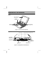
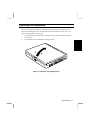
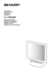
Appearance of the Notebook
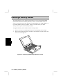
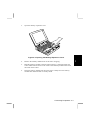
Front
Color LCD Screen
(See page 3-19)
Keyboard
(See page 3-14)
Stereo Speakers
(See page 3-25)
GlidePoint
(See page 3-16)
Figure 1. The Front of the Notebook
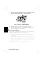
Right Side
Audio Volume
Audio Connectors (See page 3-26)
PC Card Slot
Eject Button
(See page 3-21)
PC Card Slot
(See page 3-21)
S-Input Connector
Floppy Disk Drive
(See page 4-14)
(See page 3-11)
Modem Jack
Video Input Jack
(See page 3(See page 4-14)
24)
Telephone Jack
Figure 2. The Right Side of the Notebook
xviii
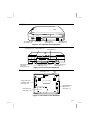
Left Side
AC Adapter Jack
(See page 1-5)
Cooling Fan
CD-ROM Drive
(See page 3-7)
Power Switch
(See page 1-8)
Figure 3. The Left Side of the Notebook
Rear
CRT Connector
(See page 4-10)
PS/2 Keyboard/Mouse
Connector
(See page 4-12)
Bottom
Video Output Jack
(See page 4-13)
Parallel Port
(See page 4-8)
Expansion Bus Connector
(See page 4-16)
RS-232C Serial Port
(See page 4-11)
Figure 4. The Rear of the Notebook
Reset Switch
(See page 1-11)
Stand
Floppy Disk Drive
or Battery Pack
(See page 1-3)
CD-ROM Drive or
Battery Pack
(See page 1-3)
Hard Disk Drive
(See page 3-13)
Figure 5. The bottom of the Notebook
xix
CHAPTER
1
Quick Setup
Your notebook is designed and pre-configured for easy setup and use. This chapter
describes the steps you should follow to get the notebook up and running as quickly
as possible. You should read this chapter first.
Getting Started
This chapter explains the whole procedure to get your notebook up and running in
the following sequence.
1.
Unpacking the Notebook
2.
Installing the Battery Pack
3.
Connecting to AC Power
4.
Opening the Notebook
5.
Turning on the Power
6.
Adjusting Screen Brightness
7.
Setting up Windows 95
8.
Setting Initial Condition
9.
Shutting Down the System
1
Quick Setup 1-1
Unpacking the Notebook
Your notebook comes securely packaged in a sturdy cardboard shipping carton.
Upon receiving your notebook, open the carton and carefully remove the contents. In
addition to this Operation Manual, the shipping carton should contain the following
items:
1
•
•
•
•
•
•
•
•
•
•
•
•
•
•
•
•
•
•
•
Notebook computer
AC power cord
Lithium-ion battery pack
Audio connection cable
TV connection cable
S terminal video cable
Blank battery filler cover
Windows 95 CD-ROM
Backup CD-ROM
CD-ROM Setup Boot Disk
Windows 95 manual and license
Reinstallation Instructions
TranXit Quick Reference Guide
IntelliLink Import/Export User’s Guide
PC-cillin ’95 Virus Scanner User’s Guide
Phoenix PowerPanel User’s Guide
Modem cable (US only)
Super Voice User’s Guide (US only)
AT Command Reference Manual (US only)
Carefully inspect each component to make sure nothing is missing or damaged. If
any of these items is missing or damaged, notify your dealer immediately. Be sure to
save the shipping materials and carton in case you need to ship or store the notebook
in the future.
1-2 Unpacking the Notebook
Installing the Battery Pack
The notebook has been shipped with the battery separate to preserve battery life.
You can install up to two battery packs, one into the CD-ROM drive slot and the
other into the 3.5-inch floppy disk drive slot.
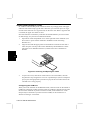
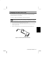
The following steps describe how to install the battery pack into either the CD-ROM
drive slot or the floppy disk drive slot:
1.
Make sure the notebook is not connected to AC power.
2.
Place the notebook on a flat surface, then lift the notebook by the left side and
turn it upside down.
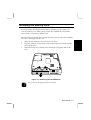
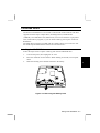
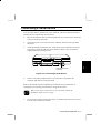
3.
Slide the retaining levers inward on the desired slot, then gently slide out the
drive.
Figure 1-1. Removing the CD-ROM Drive
You can remove the floppy disk drive similarly.
Quick Setup 1-3
1
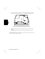
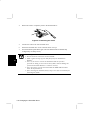
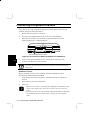
4.
If you have selected the CD-ROM slot, slide the supplied blank battery filler
cover into place as shown. This cover is not needed for the floppy disk drive.
1
Figure 1-2. Installing Blank Battery Filler Cover
5.
With the bottom of the battery pack facing up, insert the connector into the
notebook.
When the battery pack clicks into place, slide the retaining levers outward.
When using the battery pack for the first time, connect the notebook to an AC power
source and charge the battery pack fully.
1-4 Installing the Battery Pack
Connecting to AC Power
The notebook can be powered by either the rechargeable battery pack or the built-in
AC adapter. You will find detailed instructions on using both power sources in
Chapter 3, but to get the notebook up and running for the first time, follow the steps
below to prepare the battery pack and attach the AC cord.
Before using the notebook for the first time, charge the battery pack by attaching the
AC cord, as follows.
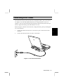
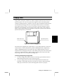
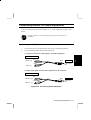
1.
Connect the female end of the AC cord to the AC jack on the left side of the
notebook.
2.
Connect the male end of the AC cord to a wall outlet.
Figure 1-3. AC Cord Connections
Quick Setup 1-5
1
When you connect the AC cord to the notebook and to a wall outlet, the outlet
supplies power to the notebook and recharges the battery.
Whenever possible, keep the AC cord plugged into the notebook and a wall outlet to
recharge the battery. Although not necessary, it is also a good idea to protect the
display panel by always lowering it when the notebook is powered off.
It is important for the notebook to be located near the electrical outlet
while connected, and for the AC plug to be easily removable.
1
Always hold the plug (not the cord) when pulling out the AC cord from
the outlet.
1-6 Connecting to AC Power
Opening the Notebook
At the front of the notebook you will find a retaining button on the display panel
which locks the display in the closed position when the notebook is not in use. To
raise the display follow these steps:
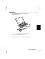
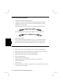
1.
Press the display lock latch until the display panel releases, and then raise the
LCD screen.
2.
Tilt the display to a comfortable viewing position.
1
➁
➀
Figure 1-4. Raising the Display Panel
Quick Setup 1-7
Turning on the Power
You can find the power switch near the center of the left side of the notebook. Press
the switch firmly to turn it on.
The power switch does not operate with only a light touch.
1
After a few seconds, the notebook begins to execute the Power-On-Self-Test (or
POST) which is automatically run whenever the notebook is turned on. It checks the
memory, keyboard, system board and other components of your notebook before the
notebook begins normal operation.
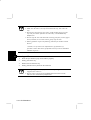
The notebook may alert you with a message that the configuration is
invalid. Press the F2 key to enter the Setup Utility. To load the default
configuration, press the F9 key. Then press the Esc key, select “Save
Change & Exit,” and press the Enter key twice.
1-8 Turning on the Power
Adjusting Screen Brightness
If you have trouble reading the screen, you can adjust the display through the use of
special key combinations. The display control key combinations are as follows:
Fn
F6
This key combination decreases LCD screen brightness incrementally.
Fn
F7
This key combination increases LCD screen brightness incrementally.
1
Quick Setup 1-9
Setting up Windows 95
The first screen lets you know what is happening by the following steps:
•
•
•
Gathering information
Configuring your computer
Restarting your computer
To set up Windows 95, follow the instructions on the screen. It takes approx. 20
minutes to complete all of the Setup procedures.
1
1-10 Setting up Windows 95
Setting Initial Condition
After setting up Windows 95, you need to set the initial condition of this notebook in
the following procedure.
1.
2.
Double-click the Sharp Startup icon at the upper right corner of the screen.
When the message appears, click OK. The system restarts, and the initial
condition is set.
In this condition, several programs are set in the StartUp folder, and the SHARP
original wallpaper is displayed on the screen as default.
The instructions in the documents attached to the notebook premises that
you have set the initial condition.
Quick Setup 1-11
1
Shutting Down the System
To power off the notebook, from the Start menu, select Shut Down and then click
Yes. The notebook turns off automatically.
If the notebook becomes hot during the operation, the cooling fan will
continue to turn around until the temperature is low enough after you
shut down the system.
If You Cannot Shut Down
1
Software Reset
You can reset the software when you encounter software problems which lock up the
notebook. To reset the system or “reboot,” press the Ctrl+Alt+Delete keys
simultaneously. Then, follow the instructions on the screen: press the
Ctrl+Alt+Delete keys again. The notebook restarts. This is known as a “warm
boot.”
Resetting may cause the data loss. Use the software reset only if the
normal Windows 95 Shut Down does not work because of software
malfunction. Although resetting will not damage the system, you may lose
the data you are processing.
Power Switch
You can turn off the notebook with the power switch when you encounter hardware
or software problems which lock up the system. Press the power switch on the left
side of the notebook for five seconds. The notebook shuts down.
Hardware Reset
You can use the hardware reset switch only if the power switch does not turn off the
notebook. The switch is in the small hole at the bottom of the notebook. Press this
switch with the tip of a pencil or ballpoint pen. The notebook shuts down.
Before turning it back on, wait at least 10 seconds after turning off the
notebook. Turning the power off and on in rapid succession can damage
the notebook’s electrical circuitry.
1-12 Shutting Down the System
CHAPTER
2
Customizing Your Notebook
As with most other computers, your notebook employs a Setup Utility that stores the
basic bootup configuration and power management settings. This chapter describes
how to customize your notebook using the Setup Utility.
Running the Setup Utility
Your notebook has been properly set up and configured prior to delivery. However,
you may find it is necessary to use the notebook’s Setup Utility to change system
configuration information, such as time and date, port assignments, passwords or
power management settings. The Setup Utility can be accessed when “Press <F2> to
enter setup” appears at boot time.
The settings you specify with the Setup Utility are recorded in a special area of
memory called CMOS RAM. This memory is backed up by an independent backup
battery so that it will not be erased when you turn off or reset the system. Whenever
you turn on the power, the system reads the settings stored in CMOS RAM and
compares them to the equipment check conducted during the power-on-self-test
(POST). If an error occurs, an error message is displayed on screen, and you are
prompted to run the Setup Utility.
The Setup Utility consists of four menu pages and the Exit page, as follows:
1.
Main: basic system configuration (time/date, disk drive and memory settings)
2.
Advanced: device interface configuration (I/O ports, sound settings)
3.
Security: password settings
4.
Power: Power management (battery saving settings)
5.
Exit: exit the Setup Utility
Using the Setup Utility
The following keys are used to maneuver among Setup options and to change values:
Use the cursor keys to move from one option to another.
PgUp
Press these keys to move to the first or last item.
PgDn
Customizing Your Notebook 2-1
2
Press this key to increase the numeric value or change to the
next value of an option.
Press this key to decrease the numeric value or change to the
previous value of an option.
2
Esc
Press this key to enter the Exit menu. From the Exit menu, you
can make default settings or load previous values and so on.
F9
Press this key to replace only the settings on the current setup
page with their default values (date and time are not changed).
F10
Press this key to restore the values you previously saved (date
and time are not changed).
Press this key to display online help for the Setup Utility.
F1
2-2 Running the Setup Utility
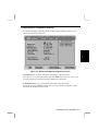
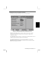
Changing Main Configuration Settings
The Main setup page of the Setup Utility which is illustrated below allows you to
change the following information.
2
Figure 2-1. Setup Utility Main Configuration Screen
System Time Allows you to change the system time, using the format
hour:minute:second (24-hour format). Press the Enter key to move the cursor. You
can also change the system time from the Windows Control Panel.
System Date Allows you to change the system date, using the format
month/day/year. Press Enter to move the cursor. You can also change the system
date from the Windows Control Panel.
Customizing Your Notebook 2-3
Diskette A This setting should generally be set to 1.44MB,3½".
Hard Disk Type Determines the type of the internal hard disk. If it is set to Auto, the
type of the new hard disk will automatically be identified when the hard disk is
replaced.
Boot Sequence Determines where the boot program will look for operating system
files. The default is C: then A:, which checks the hard disk first, and only checks the
floppy disk drive if no system files are found on the hard disk.
Other options for this setting are A: then C:, which check the floppy disk drive (A:)
first, and if no system disk is found in the drive, the system boots from the hard
drive; C: only, which never checks for system files on the floppy disk drive.
2
Internal Numlock If you are using an external keyboard, you may want to use the
external keyboard’s NumLock key. The NumLock key of the external keyboard also
effects the built-in keyboard, and the built-in keyboard turns on the NumLock status.
To avoid this, set this option to Disabled before using the NumLock key on an
external keyboard.
Key Click Enables or disables audio feedback of key click.
Video Input Determines whether you use the built-in capture board or the ZV port.
System Memory Indicates the size of ‘conventional’ memory to be made available
directly to MS-DOS. It always shows 640 KB.
Extended Memory Indicates the size of extended memory found by the BIOS
during its POST. The value displayed is the amount of memory located above 1MB
in the microprocessor’s memory address map. Because the notebook ships with a
minimum of 16MB of memory as standard, this value will not be less than 15360KB.
The notebook automatically updates the value here when you enter the Setup Utility
after you add an optional memory module.
2-4 Running the Setup Utility
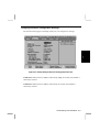
Changing Advanced Configuration Settings
The Advanced setup page of the Setup Utility lets you configure I/O settings.
2
Figure 2-2. Setup Utility Advanced Configuration Screen
COM1 Port Indicates the I/O address and interrupt (IRQ) to be used when COM1 is
selected by software.
COM2 Port Indicates the I/O address and interrupt to be used when COM2 is
selected by software.
Customizing Your Notebook 2-5
COM1/COM2 Function Determines which combination of Serial Port, FAX
modem or IR is assigned to the COM1 and COM2.
IR Type Determines the communications compatibility mode for the infrared port.
However, this setting should be fixed at IrDA 1.1. To change the IR type, refer to the
section of Infrared Communications in Chapter 3.
LPT Port Indicates the I/O address and interrupt to be used when printer port LPT1
is selected by software.
LPT Mode Allows you to configure the notebook’s parallel port as an Output Only
printer port, a Bi-Directional port, or as an Extended Capabilities port (ECP).
2
Diskette Controller This setting should be Enabled whenever the internal floppy
disk drive is installed. If you remove the drive, for example, to install a battery, this
setting should be Disabled.
Internal Audio Enables or disables the internal audio. It sets the I/O Channel, IRQ
Channel, 8bit DMA Channel, and 16bit DMA Channel.
Plug & Play O/S The default value is No. You can set it to Yes if necessary.
If your notebook, connected with peripheral devices such as a PC card, is
not working well, set Plug & Play O/S to Yes. The change of the setting
may solve the problem. In this case, however, you cannot use a PC card
after starting up the notebook in MS-DOS.
Large Disk Access Mode Available settings are DOS (the default), or Other. Use
the DOS setting unless you install another operating system, such as UNIX.
2-6 Running the Setup Utility
Changing Security Configuration Settings
The Security setup page of the Setup Utility lets you set passwords.
2
Figure 2-3. Setup Utility Security Configuration Screen
Supervisor Password is Indicates whether a Supervisor Password is required
(Enabled) or not. If enabled, the password will be required to change certain
configuration settings.
User Password is Indicates whether a User Password is required (Enabled) or not. If
enabled, the password will be required to use the notebook.
Set Supervisor Password Select this field and press Enter to set a password.
Passwords can be up to seven characters in length, and can be cleared by pressing
Enter without typing any characters.
Customizing Your Notebook 2-7
Set User Password Select this field and press Enter to set a password. Passwords
can be up to seven characters in length, and can be cleared by pressing Enter
without typing any characters.
In order to set the User password, the Supervisor password must be set in advance.
If you lose your password, you will be unable to access the notebook or
change the configuration. Make sure to select a password you will never
forget, or write it down and protect it in a secure place. Otherwise, you
will have to contact your dealer for assistance.
Password on boot Defines whether the system prompts you for the password during
the bootup. If having set this option to Enables, you need to input the supervisor
password or user password when booting.
2
Power Management Security If you set this setting to Enabled, when the notebook
resumes from the Suspend to Disk mode, you will be prompted to enter the
password.
Diskette access Limits read/write access to floppy disks according to password entry
at the last bootup. If set to Supervisor, floppy disk access will be enabled only if the
Supervisor password was entered when the notebook was last booted. If set to User,
access is enabled if either the Supervisor or User password was entered.
Fixed disk boot sector Prevents possible virus infections from making disks
inaccessible. When this selection is Write protect, write access to the boot sector of
hard and floppy disks is inhibited. However, note that some types of viruses can still
cause damage to program and data files. To change the partitioning of the hard disk
or to install a new file system, this setting must be Normal.
If you set the conditions below, you cannot access the floppy disk drive
• Supervisor password is set,
• Password on boot is disabled, and
• Diskette access is set to Supervisor.
2-8 Running the Setup Utility
CHAPTER
3
Using Your Notebook
This chapter describes basic features and procedures for using the notebook. Topics
covered include power sources, using CDs, diskettes and the hard disk drive, the
GlidePoint, PC Cards and devices, the video subsystem, and enjoying the audio
capabilities of the notebook.
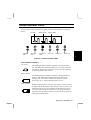
Status Indicator LEDs
The nine status indicator LEDs are located just above the keyboard, as illustrated
below.
AC Power
Battery Power
Battery Status
N
CD-ROM
Drive
Hard Disk
Drive
Floppy Disk
Drive
Num Lock
A
Caps Lock
Scroll Lock
3
Figure 3-1. Status Indicator LEDs
Power Status Indicators
AC Power
This LED lights green when the notebook is being powered by
AC, and blinks when Suspend to RAM is active using AC power.
The LED is off when the notebook is off or powered by batteries,
or when Suspend to Disk is active.
Battery Power
This LED lights green when the notebook is being powered by
batteries, and blinks when Suspend to RAM is active using
battery power. The LED is off when the notebook is off or
powered by AC, or when Suspend to Disk is active.
Battery Status
During normal operation, this LED stays off as long as the battery
is charged. When the battery charge drops to 20% of capacity, the
LED lights red and a 10-second alarm sounds. When this occurs,
save your work to disk, and connect AC to recharge the battery.
Please note that no alarm sounds if you are using the computer in
the Suspend to RAM mode.
Using Your Notebook 3-1
If the battery is allowed to discharge further during operation,
this LED starts blinking red and a continuous alarm sounds,
indicating a critical battery condition. During Suspend to RAM,
however, the alarm does not sound.
The Suspend to Disk mode activates automatically, and you will
have to connect AC or replace the battery with a charged pack to
resume working.
When AC is connected, this indicator glows green if the battery
pack is fully charged, or orange if the battery is being charged. If
a fault occurs with the battery or charger, this indicator blinks
orange. Try removing the battery pack, then re-installing it. If the
indicator still blinks orange, there may be a problem with the
notebook or the battery pack.
Other Indicator LEDs
CD-ROM Drive
This indicator glows green while the CD-ROM is being accessed.
Wait for this indicator to turn off before removing the CD-ROM.
3
Hard Disk Drive
This indicator glows green while the hard disk drive is being
accessed. To avoid data loss, never remove the drive, or turn off or
reset the notebook when this indicator is lit.
Floppy Disk Drive
This indicator glows green while the floppy disk drive is being
accessed. To avoid data loss, never remove the diskette from the
drive, or turn off or reset the notebook when this indicator is lit.
Num Lock
This indicator glows green when the keyboard Num Lock function
is engaged, to activate the keyboard’s embedded numeric keypad.
Caps N
Lock
This indicator glows green when the keyboard Caps Lock function is
engaged, causing characters to be entered in upper case.
Scroll Lock
A
This indicator glows green when the keyboard Scroll Lock function is
engaged, causing text to scroll without altering the cursor position on
screen.
3-2 Status Indicator LEDs
Power Sources
The notebook is designed to operate with one of the following power sources:
•
•
AC power from a wall outlet
one or two Lithium-ion battery packs
Use AC power whenever possible, relying on the battery pack only when AC power
is unavailable.
Using AC Power
An AC adapter is built into the notebook, to provide power for operation and to
charge the batteries when the AC cord is connected to a wall outlet. The AC input
voltage can range anywhere from 100 to 240 volts, making it suitable for use
virtually anywhere in the world with the appropriate plug adapter. The battery pack
automatically recharges while your notebook is connected to AC. If the notebook is
not powered on, total recharge time for a completely discharged battery is
approximately three hours (or five hours for two packs).
The status indicator LEDs above the keyboard indicate the state of the built-in AC
adapter, as described in the previous section.
The AC power cord provided with the notebook is appropriate for the
voltage of your local area. If you attempt to connect the notebook a wall
outlet other than your local area, check the voltage of the outlet and use
an AC power cord appropriate for the outlet.
Using Your Notebook 3-3
3
Using Battery Power
The rechargeable lithium-ion battery pack allows you to operate the notebook
without an external power source. When fully charged, a single battery pack can
supply power to your notebook for up to 2 hours; much longer periods of time may
be possible if the notebook’s advanced power management features have been
activated. You can also install a second battery pack in place of the floppy disk drive
or CD-ROM drive, to double the capacity.
The amount of time a battery charge will last will depend on the notebook
usage. Applications which heavily use the peripherals, like the floppy disk
or the CD-ROM drive, will experience shorter power on time.
3
Low Battery Indication
When your notebook senses that the battery only has enough charge to continue for a
few minutes, it will alert you to a low battery condition by blinking the red battery
status LED and sounding a battery low warning beep. The remaining operating time
depends on the power you are consuming: if you are using the audio system, PC
Card slots, CD-ROM or hard and floppy disk drives, your notebook might run out of
charge very quickly. You should always respond to the battery low indication by
connecting to AC power or turning off your notebook, or suspending your notebook
to disk. If you do not do so, the notebook will automatically suspend to disk
(regardless of the setting of the Suspend Mode option in the Setup Utility) and turn
off. The contents of the memory will be stored in the suspend-to-disk partition. You
will be unable to restart the notebook until you have connected to AC or installed a
fresh, charged battery.
If the notebook is in the Suspend to RAM mode when the battery is
critically low, the notebook will attempt to Suspend to Disk (if enabled in
the Setup Utility), and then turn off.
Charging the Battery
To recharge the battery, connect AC to the notebook as described in the previous
section and turn off the notebook. Approximately three hours are required to fully
charge a low battery(or five hours if two batteries are installed). The Battery Status
Indicator lights in orange while the battery is charging. The indicator flickering in
the recharge may indicate some trouble. Disconnect the notebook, extract the battery
pack, re-insert it, and connect the notebook to AC again. If the indicator still flickers,
the system has a problem.
3-4 Power Sources
• If you have not used the notebook for a long time, the battery may
become completely discharged. In such a case, recharging will take
more time than usual.
• If you use the notebook for a while, the battery will become hot. The
notebook starts recharging after getting back to the normal
temperature.
Maintaining the Battery Pack
You should discharge the battery pack if you do not use the notebook for a long time
and should recharge it fully before use. If the battery is fully charged and left unused
for a long time.
• The battery will discharge itself slowly, and
•
The life of the battery will be shortened.
Lithium-ion batteries do not have so-called “memory effect,”and you do
not have to deep discharge the battery pack before charging it.
3
Disposing of Battery Packs
The capacity of a battery pack is gradually decreasing while used repeatedly.
Although the deterioration rate depends on the operating temperature and
environments, the pack can sufficiently be used for 500 times, after which you
should consider purchasing a replacement battery pack that is identical to the battery
pack.
Your local area may have rules which you should follow regarding battery disposal.
In addition to the main lithium-ion battery, you should remember the small backup
battery located under the keyboard. Bring your notebook to a local dealer for
replacement of this backup battery if your notebook begins to lose its time and date
setting.
Backup batteries
The notebook has two backup batteries. The rechargeable NiMH battery prevents
loss of data during replacement of the lithium-ion battery while in the suspend mode.
However, this will not work if the battery level of the NiMH battery is low.
Therefore, power-off or suspend to disk is recommended when replacing the lithiumion battery.
The other backup battery is a non-rechargeable coin type Lithium battery for RTC.
Using Your Notebook 3-5
Battery Precautions
Handling
•
•
•
•
•
3
•
•
•
Never put the battery pack in a fire, as it could explode and cause injury.
Do not attempt to open or alter the battery pack.
Do not place the battery where it might get hotter than 60°C (140°F).
Do not allow metal objects such as jewelry to short across the battery terminals, as
it could heat up and explode.
The battery includes a circuit breaker to help protect against short circuiting.
However, covering or pressing this breaker switch hard could cause the battery to
malfunction.
Do not allow liquids to come in contact with the battery pack.
Avoid dropping the pack, or other violent shock.
Do not solder to the battery terminals.
Charging
•
Charge the battery pack only with the notebook’s built-in AC adapter.
Discharging
•
Do not use the battery pack for any purpose other than powering the notebook
computer.
Storage
•
•
Store the battery pack in a cool and dry place. Never allow the temperature to
exceed 60°C (140°F) during storage.
Recharge the battery pack after storage, before use.
3-6 Power Sources
CD-ROM Drive
The built-in CD-ROM drive is accessible on the left side of the notebook. The drive
supports all of the major compact discs, including CD-DA, CD-ROM XA
(ADPCM), CD-I and Photo CD (multisession). You can use the drive to play music
CDs, install and run programs, or you can install a battery pack in place of the CDROM drive.
The Sharp Player software provided with the computer allows you to use CDs. See
the online help included with the software for use instructions.
Installing the CD-ROM Drive
Follow the steps below to replace a battery pack with the CD-ROM drive.
1.
Turn off the power, then unplug the AC cord.
2.
Place the notebook on a flat surface. While holding its left side, turn it upside
down.
3.
Slide the retaining levers inward and remove the battery.
Figure 3-2. Removing the Battery Pack
Using Your Notebook 3-7
3
4.
Slide out the supplied blank battery filler cover.
Figure 3-3. Removing the Blank Battery Filler Cover
3
5.
Make sure the bottom of the CD-ROM drive is facing up, then push the
connectors all the way into the notebook until the CD-ROM drive clicks into
place; the retaining levers will slide out automatically.
Figure 3-4. Inserting the CD-ROM Drive
3-8 CD-ROM Drive
Inserting a CD
1.
Press the eject button to pop out the CD tray slightly.
2.
Gently pull out the tray.
3
Figure 3-5. Opening the CD Tray
3.
Place your CD, label side up, into the tray.
4.
Slightly press the center of the CD until it clicks into place.
5.
Gently push the CD tray back into the notebook.
Using Your Notebook 3-9
• When inserting a CD, do not use force.
• Make sure the CD is correctly inserted into the tray, then close the
tray.
Do
not leave the CD tray open. Also, avoid touching the lens in the
•
tray with your hand. If the lens becomes dirty, the CD-ROM may
malfunction.
• Do not wipe the lens with materials with rough surface (such as paper
towel). Instead, use a cotton swab to gently wipe the lens.
• FDA regulations require the following statement for all laser-based
devices:
“Caution, Use of controls or adjustments or performance of
procedures other than those specified herein may result in hazardous
radiation exposure.”
3
Removing a CD
1.
Press the eject button to pop out the CD tray slightly.
2.
Gently pull out the tray.
3.
Remove the CD from the tray.
4.
Gently push the CD tray back into the notebook.
• When opening the CD tray, if the CD is still spinning, wait until it has
stopped, then remove it.
• Do not remove the CD if the CD-ROM indicator LED is still lit;
otherwise the notebook may malfunction.
3-10 CD-ROM Drive
Floppy Disk
Floppy disks used by the notebook are made of magnetic material and enclosed in a
protective plastic case. The case protects the magnetic surface of the disk against
scratches, bending and dust. A shutter on the case opens automatically when inserted
into the notebook’s floppy disk drive, exposing the disk to the drive’s read/write
head, which can then retrieve, record or erase data on the disk’s magnetic surface.
When the system attempts to access a floppy disk, the disk starts to spin within its
plastic casing, and the read/write head moves to the proper position on the disk and
performs the operation you requested.
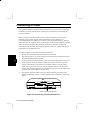
Write Protect Tab
High Density Notch
Figure 3-6. 3.5-Inch Floppy Disk
The notebook is equipped with a high-density 3.5-inch floppy disk drive, which can
read and write to either double-density (2DD) 720KB floppy disk or high-density
(2HD) 1.44MB floppy disk. Notice that both types of floppy disk have an arrow
imprinted on the front upper left corner, and a sliding write-protect tab on the bottom
left corner, as illustrated above. When opened, the write-protect tab prevents data
from being written to, or erased from, the floppy disk.
Inserting and Ejecting Floppy Disk
1.
To insert a floppy disk, hold it with the arrow facing up and towards the drive.
Slide the disk into the drive until it clicks into place.
2.
To eject a floppy disk, first ensure that the FDD indicator LED above the
keyboard is off, and then press the eject button on the drive. When the floppy
disk pops out of the drive, remove the floppy disk and store it properly.
Using Your Notebook 3-11
3
Formatting a Floppy Disk Using Windows 95
Insert a new floppy disk into the floppy disk drive, double-click My Computer then
click 3½ Floppy [A:]. From the File menu, click Format. A dialog box appears to
allow you to select some settings. Click Start to begin formatting. After completed,
the floppy disk is now ready to use.
• Never turn off or reset the notebook while the FDD indicator LED is
on.
• Insert a floppy disk properly and gently.
• Do not give an impact on the FDD.
• Always store your disks in a safe, clean container, to protect them
from the environment and magnetic fields.
• Do not install the floppy disk drive in the CD-ROM slot. The FDD
can become stuck in the slot.
3
3-12 Floppy Disk
Hard Disk Drive
Unlike a floppy disk, a hard disk drive is rigid and completely sealed in a protective,
dust-free environment. A hard disk drive works very much the same as a disk, but it
can retrieve and record data much faster and has a much larger storage capacity.
The notebook is equipped with a removable 2.5-inch integrated drive electronics (or
IDE) hard disk drive. This type of drive embodies the latest in fast, reliable mass
storage by integrating all the control circuitry necessary for operation directly onto
the drive itself. This allows the drive manufacturer to carefully optimize drive
performance.
You can also easily replace the hard disk drive, as it is installed in a special
compartment to make it easily removable. Refer to Chapter 4 for details on how to
replace the hard disk drive.
• Make regular backups of your data files from your hard disk to
floppy disks or other media.
• Never try to insert or remove the hard disk while the system is
powered on. Doing so can result in loss of data, and can damage the
system and the hard disk drive’s sensitive circuitry.
• Never turn off or reset the notebook while the HDD indicator LED
above the keyboard is lit.
• When your hard disk drive is removed from the notebook, always store
it in a safe environment free from magnetic fields.
Using Your Notebook 3-13
3
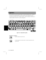
Keyboard
The notebook provides all the functionality of a full-sized desktop 101- or 102-key
keyboard. You should familiarize yourself with the special notebook function
keystrokes which allow you to quickly and easily control and adjust such features as
display brightness and access to power management.
Esc
F1
~
`
F3
2
3
F4
F5
F6
I
1
Q
Tab
Caps
Lock
Fn
4
S
Z
Ctrl
D
X
Alt
B
7
i
8
8
U
J
N
F10
F9
7
H
G
V
F8
Y
T
F
C
F7
O
6
5
R
E
W
A
Shift
3
F2
4
1
M
9
9
5
I
K
0
O
2
<
,
F12
F11
L
_
j*
+
=
-
3
: +
;
>
.
?
/
Alt
Ins
Scroll
Lock
Backspace
}
]
{
[
P -
6
Prt Sc
Sys Rq
Num
Lock
"
'
Home
PgUp
Enter
Shift
Del
Figure 3-7. Keyboard Layouts
Windows Logo Keys
opens the Windows Start menu.
provides application-specific short-cut menu equivalent to the
right button.
3-14 Keyboard
Pause
Break
PgDn
End
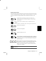
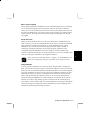
System Function Keys
The notebook has special system function keys which activate key functions printed
on keys serving dual functions. When pressed in conjunction with the Fn or Ctrl key,
these keys set specific system parameters and are sometimes referred to as “hot
keys”.
toggles between video display output to the LCD screen,
external CRT monitor, SimulScan (display on both), and the
video out jack.
F5
Fn
• When you play video or animation, this key combination may not
funktion.
• Do not use this key combination when connecting the notebook to TV.
Ctrl
Fn
F6
decreases LCD brightness.
Fn
F7
increases LCD brightness.
Fn
F11
Fn
F12
Alt
3
toggles the display on or off.
puts the notebook in suspend mode (RAM or Disk, according to
the setup selection). To resume normal operation from Suspend
to RAM, press any key. To resume from Suspend to Disk, press
the power switch.
Del
halts all operation of your notebook and commands it to reset.
This is known as a “warm boot”. The notebook will halt current
operations and restart afresh. This key combination may be
useful if you encounter hardware or software problems which
“lock up” your notebook.
Using the Ctrl+Alt+Del may result in loss of data from open
applications.
Using Your Notebook 3-15
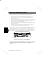
GlidePoint
Your notebook features GlidePoint, an integrated pointing device, connected
internally to a PS/2 port and compatible with the Microsoft Mouse and IBM PS/2
mouse. The GlidePoint combines high resolution fingertip control and an ergonomic
design equally suitable for left-handed and right-handed users. Most software
applications will require use of the “left” button.
3
Figure 3-8. The Integrated GlidePoint
Using the GlidePoint
Take a moment to become familiar with how the GlidePoint works.
Place Your Fingertip
Place your left or right hand next to the GlidePoint, resting your wrist naturally in a
relaxed manner. Place your thumb or forefinger on the GlidePoint.
3-16 GlidePoint
Move Your Fingertip
The rectangular pad of the GlidePoint acts like a miniature duplicate of your display.
As you slide your fingertip across the pad, the pointer on the screen, called the
cursor, moves in the same direction across the screen as your fingertip moves across
the pad. The GlidePoint is very sensitive and you don’t need to exert much pressure
on the pad at all. You’ll get the best results by sliding your fingertip over the pad
very lightly.
Point and Click
When you have placed the cursor over the icon, menu item or command that you
wish to execute, you can press the left button once or twice to execute the command.
This procedure is called “point and click” or “point and double-click”. On the
GlidePoint, you can execute point and clicking even more rapidly. Instead of
clicking by pressing the left button, you can just tap gently anywhere on the
rectangular pad of the GlidePoint. Tap twice rapidly to execute a double-click.
Unlike a traditional pointing device, the whole pad acts as if it were a left button and
each tap on the pad is equivalent to pressing the left button.
If you swap the left and right buttons, “tapping” on the GlidePoint as an
alternative method of pressing the left button will no longer be valid.
Drag and Drop
You can execute commands or move files by using “drag and drop”. In drag and
drop, you activate a file by pointing to it and clicking. However, when you click the
button, you do not release the button but instead hold it down. You can then drag the
active file around the screen by moving your finger around the pad. When you have
placed the file where you want it, for example in a new directory, release the left
button. The file will drop into the new location. You can also do drag and drop
operations using the GlidePoint as a large left button. Position the cursor over the
item that you want to drag. Gently tap twice on the pad. On the second tap, keep
your finger in contact with the pad. You can then drag the selected object around the
screen by moving your fingertip across the pad. When you lift your fingertip from
the pad, the selected object will drop into place.
Using Your Notebook 3-17
3
Changing the Configuration
Double-click the Mouse icon in the Windows Control Panel. The Mouse Properties
window allows you to change various configurations. For example, if you are a lefthanded user, you can swap the buttons over so that you can use the right button to
generate events that are normally generated by the left button. You can also change
the size of the on-screen pointer, the speed of the pointer and so on.
Connecting an External PS/2 Mouse
If you connect an external PS/2 mouse to the notebook, both the GlidePoint and the
PS/2 mouse are available for use.
Refer to the section of Connecting a Keyboard or Mouse in Chapter 4.
3
3-18 GlidePoint
Video Subsystem
The built-in display is an active matrix which is adjustable to provide comfortable
viewing.
Connecting an External Monitor
The notebook is equipped with a CRT connector for connecting an external monitor.
See Chapter 4 for instructions on connecting your notebook to an external monitor.
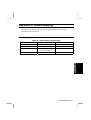
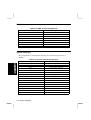
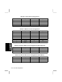
Changing Resolution and Number of Colors
To change the resolution and the number of colors,
1.
From the Start menu, select Setting - Control Panel.
2.
Double-click Display.
3.
Click the Settings tab.
4.
Select the number of the colors in the Color palette, and select the resolution in
Desktop area. Refer to the table on the next page.
5.
Click OK twice.
• You can select High Color (16 bits) or True Color (24 bits) in the Color Palette.
High Color means 65536 colors; True Color means 16,770,000 colors. If you
select True Color (24 bits), however, the LCD can display only 262144 colors.
• If you select True Color, the drawing speed of screen is decreased,
screen noise may occur, and video capturing does not work.
• For the simultaneous display of CRT and LCD, use a monitor with
1024×768 resolution capability.
• If you select 640×400 resolution, a part of a window or dialog box may
not be displayed in the screen area.
Using Your Notebook 3-19
3
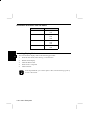
Resolution and Colors You can Select
Resolution
Colors
640 × 400
256
64K
640 × 480
256
64K
16M
800 × 600
256
64K
16M
1024 × 768
256
64K
Switching Display Mode
3
You can switch the display mode in the following procedure.
1.
From the Start menu, select Setting - Control Panel.
2.
Double-click Display.
3.
Click the Monitor tab.
4.
Select Center or Expand.
5.
Click OK twice.
In the Expand mode, you cannot capture video, and the drawing speed of
screen is decreased.
3-20 Video Subsystem
PC Cards and Devices
The notebook is equipped with two PC Card slots which can accommodate two Type
II or one Type III card conforming to the standards of the PCMCIA (Personal
Computer Memory Card International Association). The slots accept a variety of PC
Cards including ZV-port compliant cards. Some examples of PC Cards are:
•
•
•
•
•
•
Fax/Modem Card A device that connects the notebook to the telephone line for
use as a fax and/or a modem.
Network Interface Card A device that connects the notebook to a local area
network (LAN) such as an Ethernet or IBM 3270 network.
SCSI Interface Card A device that enables you to connect SCSI devices such as
MO drives, CD-ROM drives and scanners to your notebook through a SCSI
connector on the SCSI card.
Sound Card A device for sound recording and playback features (although one is
already built in).
ATA Device An AT Attachment, rotating or solid-state mass-storage device that
works like an IDE hard disk drive. An ATA device does not require an external
power source to maintain data when removed from the notebook’s PC Card slot.
SRAM Memory Card A static RAM memory device that can be formatted as a
diskette, with a write-protect switch on the edge of the card. An on-card battery
maintains the data when it is removed from the notebook’s PC Card slot.
• When using PC card utilities or drivers based on MS-DOS are located
in the directory of PCM320. For their usage, refer to the file named
MANUAL.DOC. Word for Windows or WordPad can read and print
this file although some lines may not be displayed appropriately in
WordPad.
• You cannot use ZV-port compliant cards in the upper slot nor with the
port replicator.
Using Your Notebook 3-21
3
Inserting and Ejecting PC Cards
PC Cards are inserted and ejected in much the same way as floppy disks. The upper
and lower slots both accept Type II cards. Therefore, you can insert up to two Type
II cards at the same time. For Type III card, use the lower slot. When a Type III card
is inserted, the upper slot cannot be used.
Note that some PC Card memory cards must be formatted before you can use them
for data storage; see your PC Card manual for details.
1.
Open the PC Card compartment cover on the right side of the notebook. (You
do not have to power off the notebook to handle PC Cards when using
Windows 95.)
2.
Align the card with the appropriate slot and slide the card into the slot until it
locks into place. The top of the card is identified by the manufacturer’s label.
The upper slot is identified as Socket 2, and the lower slot is identified as
Socket 1.
3
Figure 3-9. Inserting and Ejecting PC Cards
3.
To eject a PC Card, click the PC Card Control icon on the taskbar, then the
Stop button to stop using the PC card. Use a pointed object (such as a ballpoint
pen) to press the appropriate eject button to pop out the card. Then remove the
card and store it away properly.
Configuring the COM Port
When you use the notebook in the MS-DOS mode, some PC Cards use the COM3 or
COM4 port which may conflict with the COM1 or COM2 port already used by other
devices in the notebook. If your PC Card uses COM3, set the COM1 Port: in the
Setup Utility to Disabled. If your PC Card uses COM4, set the COM2 Port: to
Disabled or IR Type: to Disabled.
3-22 PC Cards and Devices
Infrared Communications
Using the IR port located on the right side of your notebook, you can wirelessly
communicate with a Sharp electronic organizer, infrared-equipped computers and
printers. Refer to the manual or online help of each application for the detail.
Positioning and Preparing the Notebook and the Target Device
Before you establish wireless communication, both the notebook and the target
device should be properly positioned. Locate your notebook in a flat place and then
place the target device so that their IR ports are in line and within approximately 30
inches (80 cm) of each other.
When using a Sharp electronic organizer, make sure they are within 15
inches (40 cm) apart.
Settings for Each Application
You need to set the IR type for each communication application.
Application
IR Type
TranXit (Variable mode)
Zrlink
Import/Export
Windows 95 Communication Application
(Direct Cable Connection, etc.)
IrDA
ASK
ASK
IrDA
Windows 95 IrDA
Communication
Disabled
Disabled
Disabled
Enabled
To adjust IR type,
1. From the Start menu, select Settings - Control Panel.
2. Double-click the IR type icon.
3. Select the appropriate IR type (ASK or IrDA).
4. Click OK.
Do not use the Setup Utility to adjust the IR type.
Enabling or disabling Windows 95 IrDA communication
Windows 95 IrDA communication is disabled by default. To enable it,
1. From the Start menu, select Settings - Control Panel.
2. Double-click Infrared.
3. Select Options.
4. Check the item of Enable infrared communication on.
5. Click OK.
Using Communication Applications in Windows 95
Your notebook assigns the physical IR port to COM2 while the Windows 95 assigns
the logical IR port to COM4 as default. To use Windows 95 communication
applications such as the Direct Cable Connection, you need to select COM4 for the
logical IR port in the application. Refer to Windows Help for details.
Using Your Notebook 3-23
3
Modem
You can use the modem built in your notebook, for data transfer, fax communication
and voice communication.
Connecting the Modem to Telephone Line
1.
Connect one end of the attached modem cable to the modem jack on the right
side of your notebook.
2.
Connect another end of the cable to the telephone line.
Using Communication Software
To use communication software,
3
1.
Turn on your notebook.
2.
Press the F2 key when the message Press <F2> to enter Setup appears.
3.
On the Advanced page of the Setup Utility, set the COM1/COM2 Function to
FAX Modem/IR or Serial Port/FAX Modem.
4.
If you assign the modem to COM1, set the COM1 Port to 3F8, IRQ4. If you
assign the modem to COM2, set the COM2 Port to 2F8, IRQ3.
5.
On the Power page of the Setup Utility, set Suspend Mode to Suspend to RAM.
6.
Set Modem Power when Suspend RAM to Enabled.
7.
Set Auto Suspend to Disk to Disabled.
8.
Press the Esc key and select Save Changes & Exit.
9.
In the communication software, set the items such as COM ports, baud rate, etc.
Refer to the software manual or online help or the manual of Windows 95.
(When using commands, refer to AT Command Reference Manual.)
The modem is available in the U.S. only.
3-24 Modem
Audio System
The audio capabilities of the notebook’s stereo speakers add sound to your software
applications, including features like an FM synthesizer, and digital recording and
playback. It is compatible with the Sound Blaster 16, and includes a number of
applications which allow you to record, compress, store and playback voice, sound
and music in the Windows environment. You can hear all the digital sound effects
and voice recordings used by the latest entertainment software.
Audio Hardware
Let’s take a look to the notebook’s built-in speakers, microphone and audio jacks.
Stereo Speakers
On either side of the LCD screen hinges are stereo speakers. The speakers are
connected internally to the notebook’s integrated audio system.
Microphone
The microphone allows you to record voice annotations and attach them to
documents using the notebook’s integrated audio system with supported software
applications.
You can greatly improve the fidelity of your audio output and input by
using external speakers and microphones.
Using Your Notebook 3-25
3
Audio Connectors
Audio Output
Jack
Audio Input
Jack
External Microphone
Jack
Figure 3-10. The Audio Connectors
You can find the audio connectors on the right side of the notebook, just above the
floppy disk slot.
3
External Microphone Jack
You can connect an external dynamic microphone for use in place of the notebook’s
built-in microphone.
Audio Input Jack
You can feed an audio signal, such as from a compact disc or tape recorder, into the
notebook’s integrated audio system through this jack.
Audio Output Jack
You can connect a set of headphones, external speakers with amplifier or an audio
recording device to this jack.
3-26 Audio System
Audio Features
The notebook’s audio capabilities include the following features:
•
•
•
•
•
Digitized audio playback capability (up to 44kHz), which faithfully plays back
and reproduces all kinds of digitized sounds with a 16-bit Digital-to-Analog
Converter (DAC). The audio system works with a number of applications that
utilize the digital voice channel to deliver realistic human speech and sound
effects.
Digitized audio recording capability (up to 44kHz) allowing digitization and
recording of any kind of sound through the notebook’s built-in microphone or an
external source.
High quality sound, dynamically filtered for low noise digital recording and
playback. Input from the notebook’s built-in microphone uses Automatic Gain
Control (AGC) to compress sound input to adapt dynamically to different
recording conditions.
Audio compression which offers real-time compression and decompression of
digital audio. Compression turns large sound files into smaller files that can easily
be stored and transferred to a diskette or even sent over a network.
Built-in power amplifier and speaker, including volume control, and an audio out
port for connection to an external pair of stereo headphones or speakers.
1. When using the built-in microphone
• For recording, make sure AGC is on and turn down the speaker
volume to avoid audio feedback.
• For playback, with AGC off, turn down the speaker volume or
mute the microphone to avoid audio feedback.
2. When using an external microphone, make sure AGC is on.
Using Your Notebook 3-27
3
Turning on Automatic Gain Control
1.
From the Start menu, select Programs - Accessories - Multimedia - Volume
Control.
2.
Select Options - Properties.
3.
Select Recording in Adjust volume for and check Microphone in Show the
following volume controls:.
4.
Click OK.
5.
Check Advacned Controls in the Options menu. The Advanced button appears.
6.
Click the Advanced button.
7.
Check 1 Automatic Gain Control.
8.
Click Close.
To turn off the AGC, uncheck 1 Recording Input Monitor in the step 7.
3
Adjusting Volume
In addition to the software controls in Windows 95, the volume control on the right
side of the notebook can be turned to adjust volume.
Audio Software
The audio system supports a large library of third party software. Most third party
software packages include music/sound drivers. All you have to do is select the
correct music/sound driver when you install the package, or follow the package’s
instructions for selecting the driver. You may select the Windows Sound System, or
Sound Blaster 16.
3-28 Audio System
CHAPTER
Connecting Peripherals
This chapter describes how to attach optional devices to your notebook. You can
attach a printer, connect an external monitor and keyboard, a mouse or modem, or
any other peripheral device that connects to a parallel, serial or PS/2
keyboard/mouse port.
4
Handling Precautions
The notebook’s components are easily damaged by static electricity. Observe the
following precautions while handling components and performing upgrades:
•
•
•
•
•
•
Power off the notebook before you do any system expansion.
Before handling system components, carefully discharge static electricity from
your body by touching an unpainted metal area. While performing upgrades,
ground yourself frequently to discharge any static electricity that may accumulate
on your body.
Avoid touching the integrated circuits on a memory module. Handle all
components by the edges.
Do not handle a component at a place where static electricity is easily generated,
such as on carpet.
Store a memory module in the anti-static wrapping or other conductive shield
such as aluminum foil.
Keep a memory module in the anti-static wrapping until installing it.
Connecting Peripherals 4-1
4
Installing a Memory Module
The notebook allows you to expand system memory via two on-board SO-DIMM
(Small Outline Dual Inline Memory Module) sockets. The SO-DIMM sockets are
easily accessible and can accept optional CE-501B (4MB×2), CE-502B (8MB×2), or
CE-503B (16MB×2) memory modules, which are available from your dealer.
Always install in pairs of two memory modules.
To upgrade memory on the notebook follow the steps below:
1.
Review the section on handling precautions at the beginning of this chapter.
2.
Pull out the locking knob on the left side of the notebook, and open the PC card
slot cover on the right side.
4
Figure 4-1. Unlocking the Memory Expansion Cover
4-2 Installing a Memory Module
3.
Open the memory expansion cover.
Figure 4-2. Opening the Memory Expansion Cover
4.
Remove the memory module from its anti-static wrapping.
5.
Hold the memory module so that the edge connector is pointed towards the
socket. Make sure the notch on the corner of the memory module mates with
the notch on the socket.
6.
Insert the memory module into the lower socket. Gently move the memory
module back and forth until it is firmly seated.
Connecting Peripherals 4-3
4
7.
Slowly move the memory module to a horizontal position until the locking tabs
snap into the retaining notches or holes at each end of the module.
Figure 4-3. Securing the Memory Module
4
8.
Repeat the same for the other memory module into the upper socket.
9.
Close the memory expansion cover. Then close the PC card slot cover and
return the locking knob to its original position.
Removing Memory Modules
To remove a pair of memory modules, for example, when you replace the pair with
another pair of modules of a larger capacity, follow these steps:
1.
Open the memory expansion cover as described in the Installing a Memory
Module section.
2.
When removing, be gentle and always start from the memory module on the
top.
3.
Push the retaining notches which secure the memory module outwards until the
memory module comes out of the nothces. Gently move the memory module
upward and remove it.
4.
Repeat the same with the other memory module of the pair.
4-4 Installing a Memory Module
Changing the Hard Disk Drive
You can easily remove the hard disk drive for upgrade or exchange with another
optional hard disk drive (CE-A40HD).
To remove or replace the hard disk drive, follow the steps below.
Before changing the hard disk drive, be sure to power off the notebook
and wait 10 seconds or more. Not doing so could damage the system and
hard disk drive’s sensitive electrical circuitry, and result in loss of data.
1.
Power off the notebook, then disconnect the AC cord.
2.
Position the notebook on a flat surface, then lift the notebook by the left side
and turn it upside down.
3.
Remove the hard disk drive screw and gently take out the hard disk drive.
4
Figure 4-4. Removing the Hard Disk Drive
Connecting Peripherals 4-5
4.
Detach the cable to completely remove the hard disk drive.
Figure 4-5. Detaching the Cable
4
5.
Connect the cable to the new hard disk drive.
6.
Fasten the hard disk drive screw removed earlier in step 3.
7.
Turn the notebook upside down again. The new hard disk will be automatically
configured by the Setup Utility.
• Do not give a shock to the hard disk.
• Do not touch the connectors on the hard disk.
• Make regular backups of your data files from your hard disk to
diskettes.
• Never try to insert or remove the hard disk while the system is
powered on. Doing so can result in loss of data, and can damage the
system and the hard disk drive’s sensitive circuitry.
• Never turn off or reset the notebook while the HDD indicator LED
above the keyboard is lit.
• After removing the hard disk, always keep it in a safe environment free
from magnetic fields.
4-6 Changing the Hard Disk Drive
Changing the Battery
If you plan to make frequent and prolonged use of the battery pack while traveling,
you may want to consider the purchase of an optional CE-A40EB battery pack from
your dealer, and keep it with you in fully charged state as a backup. Install the
second battery pack in place of the CD-ROM drive or the 3.5-inch floppy drive.
There is danger of explosion if the battery is incorrectly replaced.
Replace the battery only with Sharp’s optional battery packs. Discard
used batteries according to the dealer’s instructions.
Battery Life
The following table summarizes the battery life.
Installed Battery Pack
One
Two
Charge Time Required
(From Fully Discharged
to Fully Charged)
About 3 hours
About 5 hours
Battery Life
(When Fully Charged)
2 hours
4 hours
The battery life depends on the power management settings, application software,
etc. For details on installing the battery pack, see the Installing the Battery Pack
section in chapter 1.
Sharp sells other battery packs, but use only the CE-A40EB.
Changing the CD-ROM Drive or Floppy Disk Drive
The CD-ROM drive and the floppy disk drive are interchangeable with the battery
packs. Installation is the same as described above for the battery pack. When the
floppy drive is installed, it is accessible as drive A: to DOS and the Windows
Explorer. When the CD-ROM drive is installed, it is accessible as drive R:. Refer to
the section of CD-ROM Drive or Floppy Disk in Chapter 3.
Connecting Peripherals 4-7
4
Connecting a Printer
The notebook has both a parallel and a serial interface. You can easily connect your
notebook to a printer that has either of these types of interfaces, by following the
instructions below.
Before you begin, read the manual of your printer and determine the type of its
interface. If your printer supports both a parallel and a serial interface, it is
recommended that you configure your printer to use the parallel interface, which is
faster and easier to configure than a serial interface. Note that the notebook’s parallel
port also supports the latest EPP and ECP parallel port protocols for improved
performance and versatility with compliant printers. However, you need the special
printer driver to use EPP protocols.
To connect a printer to the notebook, follow these steps:
4
1.
Be sure both the notebook and the printer are turned off.
2.
Open the I/O port cover at the rear of the notebook with your finger and locate
the ports labeled parallel and serial.
3.
If you are using a parallel interface, connect the 25-pin male connector of your
printer cable to the 25-pin female parallel port on your notebook. If you are
using a serial interface, connect the 9-pin female connector of your printer
cable to the 9-pin male serial port on your notebook. Note that if your serial
printer cable is equipped with a 25-pin connector, you will need an adapter that
converts 9-pin serial output to 25-pin output.
4.
If necessary, attach the other end of your printer cable to your printer, and
tighten any retaining screws. A typical parallel printer connection is illustrated
below.
Printer Connector (Parallel Port)
Figure 4-6. Connecting a Printer (Parallel Port)
4-8 Connecting a Printer
5.
Power on the printer and any other peripheral devices you may have connected
to the notebook, and then turn on the notebook.
6.
If necessary, run the notebook’s Setup Utility to configure the parallel port to
respond as required by your printer and software operating environment.
7.
The newly connected printer must be configured in Windows. Refer to the
Windows 95 manual for details on setting up a printer. You can also refer to the
manual which accompanied your printer for instructions on configuring your
operating environment and application software to use the printer.
4
Connecting Peripherals 4-9
Connecting an External Monitor
Follow the instructions below to use an external monitor with the notebook.
4
1.
Be sure that both the notebook and the external monitor are turned off.
2.
Open the I/O port cover at the rear of the notebook and locate the 15-pin
female CRT connector.
3.
Connect the appropriate end of the monitor cable to the CRT connector on your
notebook. Connect the other end of the monitor cable to your monitor and
tighten monitor cable connector retaining screws.
4.
Connect the monitor power cable to the monitor, and plug the monitor power
cable into a wall outlet.
5.
Power on the monitor as well as any other peripheral devices you may have
connected to the notebook, and then turn on the notebook.
You can switch the display output by pressing Fn+F5 key combination in the order:
CRT (when connected) → LCD → CRT&LCD →CRT. For the simultaneous
display of CRT and LCD, use a monitor with 1024 × 768 resolution capability. Refer
to Video Subsystem section in Chapter 3 for the possible resolutions for the CRT.
CRT Connector
Figure 4-7. Connecting an External Monitor
You can also connect a composite video monitor, such as is used for TV signals, to
the video out jack. However, the resolution available at this jack is limited to 640 ×
400 pixels. The signal at this jack is also selectable with the Fn+F5 key
combination.
4-10 Connecting an External Monitor
Connecting a Serial Device
You can easily attach a serial device to the notebook, such as an external modem or
pointing device, by following the steps below.
1.
Be sure the notebook and any other peripheral devices you may have connected
to the notebook are turned off.
2.
Open the I/O port cover at the rear of the notebook and locate the 9-pin male
serial port.
3.
Attach the interface cable from your serial device to the notebook’s serial port.
If necessary, attach the other end of the interface cable to your serial device.
Tighten down any retaining screws.
RS-232C Serial Port
Connector
Figure 4-8. Connecting a Serial Device
4.
Power on any other peripheral devices you may have connected to the
notebook, and then turn on the notebook.
Refer to the manual which accompanied your serial device for instructions on
configuring your operating environment to recognize the device.
When connecting a serial mouse to your notebook, disable the
GlidePoint. Refer to the next page.
5.
On the Advanced page of the Setup Utility, set COM1/COM2 function to Serial
Port/IR or Serial Port/Fax modem.
Connecting Peripherals 4-11
4
Connecting a Keyboard or Mouse
If you wish to use a full size desktop keyboard or external PS/2 mouse with your
notebook, follow the instructions below.
1.
Be sure that the notebook is turned off.
2.
Locate the PS/2 keyboard/mouse port on the rear of the notebook.
3.
Attach the PS/2 cable from your mouse or keyboard cable to the PS/2
keyboard/mouse port, as illustrated below.
PS/2 Keyboard/Mouse Connector
Figure 4-9. Connecting an External Keyboard or PS/2 Mouse
4
4.
Power on any other peripheral devices you may have connected to the
notebook, and then turn on the notebook.
Never connect or disconnect PS/2 devices to the PS/2 keyboard/mouse
port when the notebook is powered on. This may cause the notebook to
malfunction.
GlidePoint Control
When connecting a mouse to your notebook, disable the GlidePoint. When
disconnecting, enable back the GlidePoint.
1.
From the Start menu, select Programs - SHARP Applications - GlidePoint
Control.
2.
Select Disables or Enables GlidePoint.
3.
Click OK.
• Make sure the mouse is enabled before disabling the GlidePoint. If the
mouse is not enabled, the cursor does not move when you move the
mouse.
• If the system enters the suspend mode while the GlidePoint is disabled,
the GlidePoint becomes enabled after resuming from the suspend
mode.
4-12 Connecting a Keyboard or Mouse
Connecting Audio/TV/Video Equipment
You can connect the notebook to an audio, TV, or video equipment, using the steps
below.
In some countries, the video output jack of your notebook is not
available.
Connecting Audio Equipment
1.
Turn off the power to the notebook as well as any connected peripherals.
2.
Use the following audio cable for the connection:
To output the notebook’s audio signal to the audio equipment:
Audio Equipment
Red
Black
LINE IN (R)
Notebook
Audio Output
Jack
White
LINE IN (L)
To input audio signal from the audio equipment to the notebook:
Audio Equipment
Red
Black
LINE OUT (R)
Notebook
Audio Input
Jack
White
LINE OUT (L)
Figure 4-10. Connecting Audio Equipment
Connecting Peripherals 4-13
4
Connecting Video Equipment
1.
Turn off the notebook and its peripherals.
2.
Connect one end of an attached cable to the output terminal of the video
equipment, and connect the other end to the video input jack or S video
connector of your notebook.
When inputing normal video signals to the notebook, use the TV cable.
When inputing S-video signals to the notebook, use the S-video cable.
4
3.
Turn on the notebook.
4.
Press the F2 key when the message Press <F2> to enter SETUP appears.
5.
On the Main page of the Setup Utility, set Video Input to Video Capture.
6.
Press the Esc key and select Save Changes & Exit. The system restarts.
Connecting TV
1.
Turn off the power to the notebook as well as any connected peripherals.
2.
Plug one end of the video cable into the video output jack on the notebook.
3.
Plug the other end into the video input jack of the TV.
4.
Turn on the power to the TV as well as the peripherals.
5.
Power up the notebook.
6.
Switch the TV to the video mode.
7.
From the Windows Start button, select Settings - Control Panel.
8.
Double-click Display.
9.
Select Settings.
10. Set Color palette to 256 Color or High Color (16 bit), and Desktop area to 640
× 400 pixels. Then click OK.
4-14 Connecting Audio/TV/Video Equipment
11. Click Yes to restart the system.
12. From the Start menu, select Settings - Control Panel - Display.
13. Select Monitor.
14. In Monitor Select, select TV.
15. Click OK. The screen is switched from the LCD to the TV.
16. To the question “Do you want to keep this setting?” click Yes. Switching is
completed.
• To output to a TV using the video output jack, do not connect an
external monitor to the CRT connector.
• If your country applies the broadcast and video standard as NTSC
(National Television Standards Committee), you cannot connect a TV
to your notebook in the country whose standard is PAL (Phase
Alternate Line).
Restoring to LCD Display
1.
From the Start menu, select Settings - Control Panel - Display.
2.
Select Monitor.
3.
In Monitor Select, select Panel.
4.
Click OK.
Connecting Peripherals 4-15
4
Port Replicator
If you need additional ports for the notebook, you can attach the CE-A40PR Port
Replicator to the expansion bus connector on the back while the notebook is turned
off. This allows you to quickly detach or re-attach your system from or to your office
or work desk apparatus.
To install the port replilcator
1.
Turn off the notebook.
2.
Push down to open the cover of the expansion bus connector on the rear side of
the notebook.
Figure 4-11. Opening the cover of the expansion bus connector
4
3.
Connect the port replicator to your notebook. Refer to the manual provided
with the port replicator.
• If your country applies PAL (Phase Alternate Line) as the broadcast
and video standard you cannot use vido output jack on your port
replicator.
• When using PC card slots of the port replicator, use the PC card
driver preinstalled in your notebook. Do not use the driver in the
supplemental disk attached to the port replicator.
4-16 Port Replicator
Appendixes
The appendixes which follow contain additional and more advanced information on
the use and care of your notebook as well as detailed technical specifications.
Appendix A: Care and Maintenance
This appendix provides you with information on how to maintain the notebook in top
working condition.
Environment
When using or storing the notebook, try to ensure that the temperature and humidity
of the surroundings are within the following ranges:
Temperature
Operating:
Storage:
10°C to 35°C (50°F to 95°F)
–20°C to 60°C (–4°F to 140°F)
Relative Humidity (Non-condensing)
Operating
Storage
20% to 80%
10% to 90%
Travel
The notebook is designed for portability. For safety and convenience when traveling,
please follow these guidelines.
•
•
•
•
•
•
Before traveling, save your data by backing it up onto diskettes.
Take along an extra backup copy of your data.
Do not travel with a diskette in the drive.
Do not travel with the notebook powered on. This may result in loss of data
and/or damage to the hard disk drive.
Disconnect AC from the notebook.
Take along a spare, fully charged battery pack, or AC cord.
When carrying the notebook, take care not to bump it into things.
Care and Maintenance A-1
Maintenance
The notebook requires little physical maintenance. As with any piece of electrical
equipment, however, you should follow a few simple maintenance routines and
precautions so that your notebook could provide outstanding performance for many
years to come.
•
•
•
•
•
•
•
Check the AC power cord and power connectors periodically for damage. Replace
the power cord immediately if damage is found.
Keep your notebook away from rain, snow, excessive humidity, direct sunlight,
high temperatures, and extreme cold.
Try not to smoke near your notebook.
Try not to eat or drink near your notebook to avoid spillage.
Try to avoid dusty environments since dust can cause damage to your disks and
drives.
Never subject your notebook to sudden shocks or extreme vibration. Do not drop
it or hit it with other equipment.
If you suddenly move your notebook from a cold place to a warm place,
undesirable moisture may condense inside the unit. After sudden temperature
changes, allow the notebook to come to room temperature before you begin using
it. This allows any moisture inside the notebook to evaporate.
The LCD Screen
•
•
•
•
Avoid scratching the surface of the screen.
Do not leave water droplets on the screen. Water can cause permanent staining.
Do not expose the LCD screen to bright sunlight or ultra-violet radiation.
Do not expose the LCD screen to extreme temperatures. Freezing and liquefaction
of the liquid crystals may result in damage to the display.
A-2 Care and Maintenance
Cleaning the Notebook
Cabinet
Apply a small amount of dust remover to a dry, lint-free cloth and wipe the cabinet
with the cloth.
• Do not use alcohol, benzene, thinner or other strong chemical agents
that may damage the cabinet.
• Never clean the notebook while it is powered on.
Screen
The surface of the screen may become smeared and accumulate dust during use. Try
not to touch the screen with your fingers when using the system. Apply a small
amount of dilute neutral detergent to a dry, lint-free cloth, and gently rub the surface
of the screen with the cloth.
IR Port
Always keep the IR port clean, as dust on the port will interfere with data transfer.
Use a soft, dry cloth to wipe the IR port.
GlidePoint
Use a soft, dry cloth to wipe the GlidePoint.
CD
Use a soft, dry cloth to wipe a CD straight out from its center. Do not wipe in any
other directions or the disc may become damaged. Also, do not use for cleaning the
following materials such as chemicals, cleanser, record spray, anti-static spray etc.
Care and Maintenance A-3
Appendix B:
Recreating the Suspend-to-Disk Partition
51MB of your hard disk space has been reserved as the suspend-to-disk partition
when shipped from the factory. This means you can safely suspend to disk if the
notebook has 48MB of installed memory, 16MB of default plus 32MB of additional
memory module. The extra 3MB allows for the overhead of the program and data
held in video memory.
If you have destroyed the suspend-to-disk partition for any reason, you can create the
partition by the following steps.
You can back up your data in several ways, depending on the kind of
software and hardware you have access to. The backup described below
uses the Backup tool of Windows, and the floppy disk drive. This may not
be the most convenient backup method, but it does not require any
software or hardware that is not supplied with the notebook.
Carefully follow the steps below to create a new suspend-to-disk partition. Since
creating a new suspend-to-disk partition destroys all the data on the hard disk, you
must first backup all the data on the hard disk drive.
The entire procedure includes the following steps:
•
•
•
•
•
Backing up all the data of the hard disk
Deleting the current suspend-to-disk partition
Deleting the partition that contains current files
Creating the new suspend-to-disk partition
Restoring the system
Recreating the Suspend-to-Disk Partition B-1
You should prepare the following items:
•
•
•
Backup CD-ROM.
CD-ROM Setup Boot Disk.
Two or more boxes of 1.44 MB diskettes, depending on how much you have used
your hard disk.
Backing up all the data of the hard disk
1.
2.
3.
From the Start menu, select Help.
Open the topic on Backup.
Start Backup from the Help windows.
Deleting the current suspend-to-disk partition
1.
2.
3.
4.
5.
6.
7.
8.
9.
Insert the CD-ROM Setup Boot Disk into the floppy disk drive.
Reboot the notebook.
Press F2 when the message Press <F2> to enter SETUP appears.
On the Main page of Setup Utility, set Boot Sequence to A: Then C:.
On the Security page, set Fixed disk boot sector to Normal.
Press the Esc key and select Save Changes & Exit.
When the system restarts, the following message appears:
Do you want to set up Windows 95?
(To change the suspend-to-disk partition, select N.)
[Y/N]
Press the N key. A:\ prompt appears.
Type PHDISK /DELETE /PARTITION and press Enter.
Deleting the partition that contains current files
Following the above steps,
1. Type FDISK and press Enter.
2. Select 3. Delete partition or Logical DOS Drive and press Enter.
3. Select 1. Delete Primary DOS Partition and press Enter.
4. Press the Enter key, input the volume label and press the Enter key again.
5. Press the Y key and then the Enter key.
6. Press the Esc key twice.
7. Press the Ctrl+Alt+Del keys simultaneously to restart the system.
8. Press the N key.
B-2 Recreating the Suspend-to-Disk Partition
Creating the new suspend-to-disk partition
At the A:\ prompt, type PHDISK /CREATE /PARTITION and press Enter.
Creating the new suspend-to-disk partition
The size of the suspend-to-disk partition is automatically difined as the
total of the current memory size and extra 3 MB. If expanding the
memory size after creating the suspend-to-disk partition, you should
recreate the partition to renew its size.
Restoring the System
1.
2.
3.
4.
Re-install Windows 95, consulting Re-installation Instructions attached to your
notebook.
Restore the backup data according to Windows Help.
On the Main page of Setup Utility, set Boot Sequence back to C: Then A:.
On the Security page, set Fixed disk boot sector back to Write protect.
Recreating the Suspend-to-Disk Partition B-3
Appendixes
Appendix C: Troubleshooting
This appendix provides information on pinpointing and solving common problems
that you may encounter using the notebook.
Problems with your notebook can be caused by something as minor as an unplugged
power cord or as major as a damaged hard disk drive. The information in this
appendix is designed to help you find and solve minor problems. If you still have a
problem after trying all the suggested remedies in this appendix contact your dealer.
The problems that you might encounter can be divided into two basic categories:
hardware and software. Hardware problems can be further divided into being of an
electrical or a mechanical nature. You will know you have a hardware problem if, for
example, the screen is blank, the notebook cannot recognize the disk drives, or you
get an error message during the Power-On Self Test (POST).
Software problems can occur at several levels. Both your operating system and your
software application programs are capable of generating errors and error messages.
If you encounter a software error, try to determine if the error message is from your
operating system or from an application program, and refer to the appropriate
manual for possible remedies.
You can also refer to the Windows 95 manual or Windows Help program to solve
the problem. To access the Help program, click the Start button, then point to Help.
It also gives you Troubleshooting tips and Index.
Common Problems
Successful troubleshooting is the result of careful observation, deductive reasoning,
and an organized approach to solving the problem. If you encounter a problem,
begin by performing a careful visual inspection. Check the exterior of the notebook
first. If no lights are displayed, check the battery charge or power outlet, the plug and
power cord, and any power switches that may affect your notebook. If the notebook
has been connected to any peripheral devices, look for loose or disconnected cables.
You may also need to check the fuses and breakers in your electric box.
A few common problems and suggested solutions are presented in the examples
which follow.
Question: Why doesn’t the power switch function?
•
The power switch does not accept just a light touch. Depress the switch firmly.
Troubleshooting C-1
•
•
If operating from a battery, it may be discharged. Connect the AC cord.
Disconnect any peripherals such as an external mouse or keyboard, depress the
hardware reset switch on the bottom side of the notebook to reset the notebook.
Question: Why can’t I start up the notebook?
•
Use a diagnostics software available commercially to check the notebook. If you
find the hard disk is damaged, you can format the hard disk by executing the
FORMAT command from the CD-ROM Setup Boot Disk, then restore the
software using the created disks (you will lose any data files you have not backed
up). If the Windows system files on your hard disk are damaged, re-install
Windows 95 from the CD-ROM Setup Boot Disk and Backup CD-ROM.
Question: Why is the screen blank?
•
•
•
•
•
•
Press the Spacebar to see if any power management feature has blanked the
screen to save power.
Check the indicator LEDs above the keyboard to verify that the notebook is
getting power. If the power indicator is not lit, check the electrical outlet, the plug
and power cord, and any power switches that may affect your notebook.
If you are using a battery pack, make sure it has a charge remaining, and that it is
installed correctly.
Check the brightness controls for your display.
Reset the notebook by pressing the Ctrl+Alt+Delete keys.
Turn the notebook off, wait a few seconds, and then turn the notebook back on.
C-2 Troubleshooting
Question: Why can’t I use a floppy disk?
•
•
•
•
The floppy disk may not be formatted, or could be corrupted.
If you can’t write to a floppy disk, the disk may be write-protected. Eject the disk
and ensure that the write-protect tab covers the detection hole.
If you can’t write to a floppy disk, the disk may be full. Use another disk.
The system BIOS boot settings for the floppy disk drive type is incorrect. In the
Setup Utility, ensure that Drive A: is set to the proper type (1.44 MB) and that
Diskette Controller is enabled.
Question: Why do I get a non-system disk or disk error message?
•
•
•
You may have inserted a non-bootable disk in Drive A: (either a defective disk or
one without an installed operating system). Remove the disk.
Check the Setup Utility to ensure that the drive types are correctly identified.
If this message is issued when you attempt to boot from your hard disk drive,
insert a bootable disk and check the integrity of your hard disk drive.
Question: Why is the date and/or time incorrect?
•
•
Correct the date and time using the Windows Control Panel or the Setup Utility.
If the date and time are still incorrect when you reboot, contact your dealer to
change the CMOS backup battery on the system board.
Question: Why can’t I recharge the battery?
•
If the notebook has been left unused for a long time, the battery may have become
completely discharged. In this case, it may be necessary to connect AC for a few
hours before the battery begins to recharge normally.
Troubleshooting C-3
Question: Why can’t I communicate through the built-in modem?
•
•
•
•
Confirm the telephone line is properly connected tothe modem jack.
Confirm the COM1/COM2 Function in the Advanced Menu of the Setup Utility is
set to FAX modem/IR or Serial Port/FAX modem.
If using the notebook in the MS-DOS mode, confirm the setting of the
communication port in the communication software is complied with the one in
the Advanced Menu of the Setup Utility. When you set the COM1/COM2
Function to FAX modem/IR, the communication port is COM1; when you set it to
Serial Port/FAX modem, the communication port is COM2.
Read also Troubleshooting in the modem manual.
Question: Why can’t I print?
•
•
•
Double-click My Computer, then Printers. Confirm your printer is installed here.
If not, click Add Printer to install your printer.
Double-click My Computer, then Printers. Confirm printer output is set to
MSFax.
See also the Printer Problems section in the Windows Help Index.
Question: Why does the PC Card not function when I use the
COM interface?
•
The card may be attempting to use COM3 or COM4 ports in a manner that
conflicts with the COM1 or COM2 port being used by another device. You may
be able to resolve the conflict by running the Setup Utility to change the COM
port settings. If your PC Card uses COM3, set the COM1 Port: setting to
Disabled. If your PC Card uses COM4, set the COM2 Port: setting to Disabled or
IR Type: setting to Disabled.
Question: Why can’t I use an SRAM or Flash card?
•
To use an SRAM or Flash card, you need to enable the card drivers. Remove
“REM” from the following lines of CONFIG.SYS file, using Windows Notepad,
then save the file and reboot.
REM device = C:WINDOWS\SYSTEM\CSMAPPER.SYS
REM device = C:WINDOWS\SYSTEM\CARDDRV.EXE /SLOT=2
When the port replicator is connected to the notebook, the slot number
has to be “4”.
C-4 Troubleshooting
Question: Why can’t I produce sound?
•
•
•
Confirm the sound driver is installed. From the Windows Control Panel, click
System, Device Manger tab, then Sound, video and game controllers. Verify the
Audio Driver is installed. If not, install the driver from the Add New Hardware
applet in the Control Panel.
Check the Windows volume control and mute button. Click the speaker symbol
beside the clock on the taskbar to open the Volume Control window.
Is the Volume control on the right side of the notebook turned down?
Question: Why does the communication software not function?
•
To use some communication software, you have to turn off the power
management. In the Windows Control Panel, double-click the Power icon, and
set Power management to Off. After using the communication software, set Power
management back to Advanced or Standard.
The POST Error Messages
The notebook performs the Power-On Self Test (POST) every time you turn on or
reset the system. The POST is a series of system checks that verifies the correct
operation of your notebook’s hardware.
If the POST detects a critical error (e.g., a system board failure), the notebook will
halt and generate an audible alarm. If a failure is detected in an area other than the
system board (such as the keyboard), a non-critical error message is displayed on the
screen and testing is stopped. You can continue testing when a non-critical error
occurs by pressing the F1 key.
When the POST encounters an error that requires you to correct something, either a
beep code will sound or a message will be displayed in a box in the middle of the
screen. If you need to enter the Setup Utility to correct a problem, press F2.
Otherwise, press F1 to continue the boot process and ignore the error.
Troubleshooting C-5
Appendix D: System Mapping
The tables below list the memory map and system interrupt/DMA channel
assignments for the notebook.
Memory Map
Table D-1: Upper Memory Address Map
Memory Address
Description
Size
A0000-BFFFFh
Used - VGA graphics
128KB
C0000-C7FFFh
Used - Video BIOS
32KB
C8000-EFFFFh
Available (UMB and
PCMCIA Window)
160KB
F0000-FFFFFh
Used - System ROM
64KB
System Mapping D-1
DMA Channels
Table D-2: DMA Channel Assignments
DMA Channel
Assignment
DMA 0
Available
DMA 1
Used - Audio
DMA 2
Used - Floppy Disk Drive
DMA 3
Available
DMA 4
System Reserved
DMA 5
Used - Audio
DMA 6
IrDA1.1
DMA 7
Available
System Interrupts
IRQ assignments can be changed by Windows 95. The following are fixed, or
defaults.
Table D-3: System Interrupt Assignments
IRQ
Assignment
IRQ0
Used - System Timer
IRQ1
Used - Keyboard
IRQ2
Used - Slave Interrupt
IRQ3
Used - COM2, COM4
IRQ4
Used - COM1, COM3
IRQ5
Used - Audio
IRQ6
Used - Floppy Disk Controller
IRQ7
Used - LPT1
IRQ8
Used - RTC
IRQ9
Used - Software redirect VGA
IRQ10
System Reserved
IRQ11
Available
IRQ12
Used - PS/2 mouse
IRQ13
Used - NPU
IRQ14
Used - HDD
IRQ15
Used - CD-ROM
D-2 System Mapping
I/O Address Map
Table D-4: I/O Address Map
Address
000-01F
020-021
040-05F
060-06F
070-07F
080-08F-091
092-09F
0A0-0A1
0C0-0DF
0F0-0FF
1F0-1FF
170-17F
200-207
200-20F
240-253
2F8-2FF
330,331
350-35F
376,377
378-37A
388-38B
3B0-3BB
3CO-3DF
FCFC-FCFF
3F0-3F7
3F8-3FF
CF8-CFF
Device
DMA Controller 1
Interrupt Controller 1
Timer/Counter
Keyboard Controller
RTC & NMI Mask
DMA Page Register
System Control Port
Interrupt Controller 2
DMA Controller 2
Math Coprocessor
Hard Disk Controller
CD-ROM
Game port
System Controller Register
Audio Chip
Serial Port 2
MIDI
IrDA1.1
CD-ROM
Parallel Port
Audio Chip
VGA Controller
VGA Controller
PCMCIA Chip
Floppy Disk Controller
Serial Port 1
PCI Bus
System Mapping D-3
Appendix E: Port Pin Assignments
The tables below lists the pin assignments for the notebook’s various ports.
Table E-1: Parallel Port Pin Assignments
Pin
Standard
EPP
ECP
1
Strobe
Write
Strobe
2
PData 0
PData 0
PData 0
3
PData 1
PData 1
PData 1
4
PData 2
PData 2
PData 2
5
PData 3
PData 3
PData 3
6
PData 4
PData 4
PData 4
7
PData 5
PData 5
PData 5
8
PData 6
PData 6
PData 6
PData 7
9
PData 7
PData 7
10
Ack
Intr
Ack
11
Busy
Wait
Busy, PeriphAck(3)
12
PE
(NU)
PError,
nAckReverse(3)
13
Select
(NU)
Select
14
Autofd
Datastb
AutoFd, HostAck(3)
15
Error
(NU)
Fault(1),
PeriphRequest(3)
16
Init
(NU)
Init(1),
ReverseBost(3)
17
Selectin
Addrstrb
Selectin(1,3)
18-25
Ground
Ground
Ground
Port Pin Assignment E-1
Table E-2: Serial Port Pin Assignments
Pin
Signal
Pin
Signal
1
DCD
6
DSR
2
RD
7
RTS
3
SD
8
CTS
4
DTR
9
RI
5
GND
Table E-3: Monitor Port Pin Assignments
Pin
Signal
Pin
Signal
1
Red
9
NC
2
Green
10
GND
3
Blue
11
NC
4
NC
12
SDA
5
GND
13
HSYNC
6
R-RTN
14
VSYNC
7
G-RTN
15
SCL
8
B-RTN
Table E-4: External PS/2 Port Pin Assignments (PS/2 Keyboard)
Pin
Signal
Pin
Signal
1
KBDATA
4
VCC
2
NC
5
KBCLOCK
3
GND
6
NC
Table E-5: External PS/2 Port Pin Assignments (PS/2 Mouse)
Pin
Signal
Pin
Signal
1
MSDATA
4
VCC
2
NC
5
MSCLOCK
3
GND
6
NC
E-2 Port Pin Assignment
Appendix F: Technical Specifications
The table below shows the physical and technical characteristics of the notebook.
Table F-1: Notebook Specifications
Specification
CPU
PC-9080
Intel Pentium 133MHz
System BIOS
256KB Flash EPROM
On board Memory
16MB EDO RAM standard (max. 48MB)
Expandable with the pair of 4, 8 or 16MB memory modules
(2 sockets)
L2 Cache
256KB PBSRAM
CD-ROM
6-time speed, interchangeable with battery pack
Floppy disk drive
3.5", 1.44MB floppy disk drive, interchangeable with battery pack
Hard disk drive
Removable 2.5" hard disk drive
Display
12.1" TFT Active Matrix 64k-Color LCD panel
1024 × 768 resolution
Video Controller
PCI-bus SVGA controller with Windows 95 DCI accelerator.
Simultaneous LCD/CRT display capability, up to 1024 × 768
resolution for CRT, 2MB Video memory.
Keyboard
Windows 95 87/88-key keyboard
Pointing device
GlidePoint (touch-sensitive control pad) with 2 buttons
PC Card slots
PCMCIA 2.1 Type II × 2 or Type III × 1, ExCA compliant, ZV-port
compliant (only one slot)
Audio
Sound Blaster 16 compatible sound board, Built-in microphone and
stereo speakers, External microphone jack, stereo line-in and lineout jacks
Video
Video output jack for composite video monitor, Video input jack
and S-input connector
I/O Ports
RS-232C serial port, Parallel port
CRT connector, PS/2 keyboard/mouse port
IR port (IrDA:115Kbps/4Mbps, ASK:9600bps)
Expansion connector (Port Replicator)
Modem (US only)
28.8 Kbps FAX/Modem with modem jack and telephone jack
Technical Specifications F-1
Power supply
One or two 2500-mAh rechargeable Lithium-ion battery
packs (in place of CD-ROM and/or floppy drive), or built-in
AC adapter (must be used when both CD-ROM and floppy
drives are installed).
Second Battery Pack is an option.
Battery life: approx. 500 charge/discharge cycles with
1.5-2.5 hours operation per cycle, per pack (3-5 hours with
two)
AC Adapter
Built-in auto-switching AC adapter
(100V to 240V, 50/60 Hz)
Dimensions
11.69 (w) × 9.65(d) × 2.28(h) inches (297 × 245 × 58 mm)
Weight
7.5 1b. (3.4 kg)
Table F-2: Optional Memory Module Specifications
Specification
CE-501B
CE-502B
CE-503B
Capacity
4MB (Eight 1M × 4,
70ns DRAMs) × 2
8MB (Four 2M × 8,
70ns DRAMs) × 2
16MB (Eight 4M ×
4, 70ns DRAMs) × 2
Size
2.35(w) × 1(d) × 0.15(h) inches (59.69 × 25.4 × 3.8 mm)
Weight
0.013 1b. (6.0 g)
0.012 1b. (5.5 g)
0.017 1b. (7.5 g)
Table F-3: Optional Hard Disk Drive Specifications
Specification
CE-A40HD
Capacity
1.1GB
Size
2.95(w) × 4.53(d) × 0.98(h) inches
(75 × 115 × 25 mm)
Weight (including cover)
0.40 lb. (180 g)
F-2 Technical Specifications
Table F-4: Optional Battery Pack Specifications
Specification
CE-A40EB
Capacity
2500mAh
Size
5.18(w) × 4.57(d) × 0.98(h) inches
(131.5 × 116 × 24.8 mm)
Weight
0.95 lb. (430 g)
Table F-5: Optional Port Replicator Specifications
Specification
CE-A40PR
Ports
One PC Card Type III (two PC Card Type II),
One each serial, parallel, VGA, PS/2 keyboard,
PS/2 mouse, MIDI/Joystick, Stereo Line-in,
Stereo phones-out, Video Out
Powered by notebook supply
Size
11.7(w) × 5.7(d) × 3.03(h) inches
(298 × 145.3 × 77 mm)
Weight
3.43 1b. (1.55 kg)
Technical Specifications F-3