1
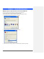
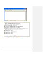
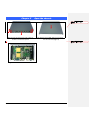
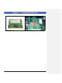
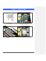
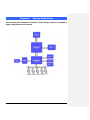
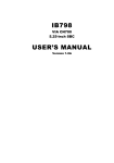
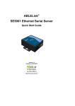
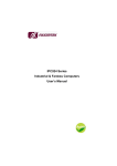
FWA7304 Series
Network Appliance
User′s Manual
Version: 1.0
Table of Contents
Chapter 1
Introduction ................................................................................................................... 3
Chapter 2
System Specification ................................................................................................... 4
Chapter 3
Hardware Configuration.............................................................................................. 5
Chapter 4
Console Mode Information ......................................................................................... 6
Chapter 5
Opening the chassis .................................................................................................... 8
Chapter 6
Removing and Installing CompactFlash Card ....................................................... 9
Chapter 7
Installing the Mini-PCI card ...................................................................................... 10
Chapter 8
Installing the 2.5” HDD .............................................................................................. 11
Chapter 9
System Architecture .................................................................................................. 12
FWA7304 Series User’s Manual
1
Foreword
To prevent damage to the system board, please handle it with care and follow the measures below,
which are generally sufficient to protect your equipment from static electricity discharge:
When handling the board, use a grounded wrist strap designed for static discharge elimination grounded
to a metal object before removing the board from the antistatic bag. Handle the board by its edges only;
do not touch its components, peripheral chips, memory modules or gold contacts.
When handling processor chips or memory modules, avoid touching their pins or gold edge fingers.
Return the Network Appliance system board and peripherals back into the antistatic bag when not in use
or not installed in the chassis.
Some circuitry on the system board can continue to operate even though the power is switched off.
Under no circumstances should the Lithium battery cell used to power the real-time clock be allowed to
be shorted. The battery cell may heat up under these conditions and present a burn hazard.
WARNING!
1. "CAUTION: DANGER OF EXPLOSION IF BATTERY IS INCORRECTLY REPLACED.
REPLACE ONLY WITH SAME OR EQUIVALENT TYPE RECOMMENDED BY THE
MANUFACTURER. DISCARD USED BATTERIES ACCORDING TO THE
MANUFACTURER’S INSTRUCTIONS"
2. This guide is for technically qualified personnel who have experience installing and configuring
system boards. Disconnect the system board power supply from its power source before you
connect/disconnect cables or install/remove any system board components. Failure to do this can
result in personnel injury or equipment damage.
3. Avoid short-circuiting the lithium battery; this can cause it to superheat and cause burns if touched.
4. Do not operate the processor without a thermal solution. Damage to the processor can occur in
seconds.
5. Do not block air vents at least minimum 1/2-inch clearance required.
6. In case explosion, you should change battery with same specification.
FWA7304 Series User’s Manual
2
Chapter 1
Introduction
The FWA7304 series was specifically designed for the network security &
management market.
Network Security Applications:
• Firewall
• Virtual Private Network
• Proxy Server
• Caching Server
Network Management Applications:
• Load balancing
• Quality of Service
• Remote Access Service
The FWA network appliance product line covers the spectrum from offering
platforms designed for :
• SOHO
• SMB
• Enterprise
Each product is designed to address the distinctive requirements of its
respective market segment from cost effective entry-level solutions to
high throughput and performance-bound systems for the Enterprise level.
FWA7304 Series User’s Manual
3
Chapter 2
System Specification
Processor
VIA Eden V4 CPU, 1GHz L2 Cache: 128K
Memory
DDR2 So-DIMM x 1
Chipset
Expansion slots
Ethernet
Front I/O
VIA CN700 North Bridge
Hardware Monitor
Input Rating
Power Supply
Dimensions
Voltage, Temperature, fan
32bit/33MHz Mini-PCI slot x 1
Realtek RTL8100C Fast Ethernet controllers x 4 , 10/100 Base-T
USB 2.0 ports x 2
Power LED x 1
Status LED (GPO) x 2 , Alarm LED (GPO) x 2 ,
DC == 5V, 4A
20W power adaptor. 100-240V, 50-60Hz
225mm (D) x 156mm (W) x 35mm (H)
FWA7304 Series User’s Manual
4
Chapter 3
Hardware Configuration
CPU board layout
Jumper Setting
JBAT1: Clear CMOS Contents
Use JBAT1, a 3-pin header, to clear the CMOS contents
JBAT1
Setting
Function
Pin 1-2
Short/Closed
Normal
Pin 2-3
Short/Closed
Clear CMOS
JP3: HDD UDMA Selection
JP4
Setting
Pin 1-2
Short
Pin 1-3
Short
Pin 2-4
Short
Function
BIOS Detect
Upper
UDMA33
UDMA33 Only
(Default)
JP4: CF Card Master / Slave Selection
JP4
Setting
Function
Pin 1-2
Master
Short
Pin 1-2
Slave
Open
FWA7304 Series User’s Manual
5
Chapter 4
Console Mode Information
FWA7304 supports output information via Console in BIOS level.
Prepare a computer as client loaded with an existing OS such Windows XP.
Connect client computer and FWA7304 with NULL Modem cable.
Follow the steps below to configure the Windows Hyper Terminal application setting:
1. For executing the Hyper Terminal, issue command “hypertrm”.
2. Customize your name for the new connection.
3. Choose the COM port on the client computer for the connection.
4. Please make the port settings to Baud rate 19200, Parity None, Data bits 8, Stop bits 1
FWA7304 Series User’s Manual
6
5. Power up the FWA7304, and the screen will display the following information.
6. Press <Tab> key to enter BIOS setup screen in Console mode.
Press <Del> key to enter BIOS setup screen in VGA mode.
FWA7304 Series User’s Manual
7
Chapter 5
Open the chassis
格式化: 項目符號及編號
1.
Fig. 5-1 Loosen the four screws of the chassis on
the back to remove the top lead.
Fig. 5-2 The top lead (Fig. 5-2) can be removed
from the base stand (Fig. 5-3).
格式化: 項目符號及編號
2.
Fig. 5-3 The base stand
FWA7304 Series User’s Manual
8
Chapter 6
Removing and Installing CompactFlash Card
格式化: 項目符號及編號
1.
Fig. 6-1 Compact Flash Card
FWA7304 Series User’s Manual
Fig. 6-2 Insert Compact Flash Card into the CF
interface
9
Chapter 7
Fig. 7-1 Mini-PCI card.
FWA7304 Series User’s Manual
Installing Mini-PCI Card
Fig. 7-2 Install the Mini-PCI card.
10
Chapter 8
Install 2.5” HDD
Fig. 8-1 Fasten the four screws to lock HDD
and bracket together.
Fig. 8-2 Fasten the four stands-off to lock IB798.
Blue portion for long stands-off.
Red portion for short stands-off.
Fig. 8-3 Connect IDE cable between 3.5” HDD
and IB798.
Fig. 8-4 Fix all four screws back
FWA7304 Series User’s Manual
11
Chapter 9
System Architecture
The following block diagram illustrates a basic design reference of IB798, a
highly integrated system solution.
FWA7304 Series User’s Manual
12