1
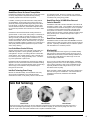
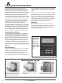
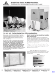
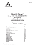
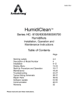
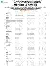
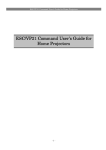
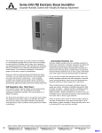
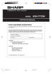
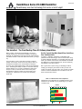
Bulletin 583
HumidiClean Series HC-6000 Humidifier
Revolutionary ionic bed technology that carries a lot of weight
The Ionic Bed. The Final Resting Place Of Ordinary Humidifiers.
Brace yourself. The Armstrong HumidiClean™ is going to
change everything you know about humidifiers. The process
starts with an extraordinary technology that will make traditional
humidifiers obsolete. Leave them dead in their tracks, you might
say.
The ionic beds you see on this page are made of a fibrous
medium: the ionic bed. There are six such beds per tank in a
HumidiClean humidifier (more in the Models HC-6500 and
HC-6700). They attract solids from the water as its temperature
rises – minimizing the buildup of solids on inner tank walls and
heating elements. So you have a humidifier that stays clean
except, of course, for the ionic beds. And once they have
absorbed their capacity of solids, the unit even tells you to
change them. It takes about 15 minutes and is absolutely
hassle free.
See For Yourself How Much HumidiClean Could Save
Over Traditional Units
As Table 1-1 illustrates, maintaining a HumidiClean with
patented ionic bed technology is more economical than caring
for either traditional cleanable or non-cleanable electronic units.
When you combine costs for labor and materials and calculate
the differences for seasonal maintenance, the new Armstrong
HumidiClean is the obvious winner.
But to get an idea of just how big your advantage could be,
multiply your savings by the number of units you have and
project your answer over a few years. Can you think of a better
reason to choose HumidiClean? We can’t either, but we can
think of several more reasons.
Table 1-1. Maintenance Cost Comparison
Maintenance cost comparison for a humidifying season using
Model HC-6100. Results may vary depending on your parts
and labor costs.
Dollars
$0 50 100 150 200 250 300 350 400 450
HumidiClean
$215 Per Season
Cleanable
$350 Per Season
Non-Cleanable
$450 Per Season
Parts
1
Labor
Armstrong Humidification Group, 816 Maple St., Three Rivers, MI 49093 – USA Phone: (269) 273-1415 Fax: (269) 273-9500
www.armstronginternational.com
HumidiClean Passes No Current Through Water
HumidiClean’s resistance-type design has a proven track record
for safety. Totally different compartments keep plumbing
completely separated from electrical components.
is to eliminate sodium. Since this is typically only necessary
approximately once every 12 hours, the unit wastes much less
hot water,thereby saving energy dollars.
In addition, Armstrong has built several other safety features
into HumidiClean. These include a key-locked access door,
password protected programmable keypad, diagnostic indicating LCD display, continual-checking diagnostic routines, highand low-water level detection, internal tank temperature sensing, overcurrent protection and connections for a Class 2 alarm
device.
HumidiClean Series HC-6000 Offers Enhanced
Control of Room RH
HumidiClean uses submersed electric heating elements to
generate steam. In other words, water quality or conductivity do
not affect the unit’s ability to generate full output on demand.
Although normally used with tap water, HumidiClean can, upon
request, be installed with deionized, demineralized, softened or
reverse osmosis water sources. Said another way: You get the
benefit of a humidifier capable of operating over a wide range of
water quality without frequent replacement of parts or bothersome, messy cleaning.
Less Scale Means Greater Efficiency
HumidiClean uses SCR controls as standard on all units for full
modulation of steam output. The humidifier's responsiveness to
increased demand is enhanced through the use of an aquastat
to maintain a minimum water temperature in the tank during
short periods of no demand. The unit also modulates fill of
makeup water into the tank to prevent reduction of steam output
during the fill cycle for consistent and responsive output of
produced steam.
HumidiClean Communications Capability
HumidiClean Series HC-6000 offers native MODBUS communications protocol as well as a Class II alarm circuit for monitoring
purposes. Optionally, HumidiClean may be ordered to operate
with either BACnet or LonWorks protocols.
Capacity is the first victim of the scale that quickly builds up in
traditional evaporative or steam-generating humidifiers. As
scale gathers in the pan or on heating elements or electrodes,
output declines. This gradually leads to a loss of humidity control. From this point on, things get steadily worse – until cleaning or the replacement of parts occurs.
Why Humidify?
HumidiClean with its remarkable ionic bed technology builds up
deposits on its ionic bed inserts instead of tank walls or heating
elements. As a result, it operates efficiently longer, its tank stays
cleaner longer, and it maintains nearly maximum output
throughout its service life.
Dry air can also increase static electricity buildup, potentially
impacting production or the use of office equipment. Computer
rooms, printing operations, clean rooms and laboratories are
especially sensitive to static charges due to dry air. Low RH
also affects indoor air quality.
Ionic Bed Technology Saves Energy
Steam is virtually a sterile medium offering many sanitation benefits over other types of humidification. It is recommended for
essentially all commercial, institutional and industrial
applications.
Because of carbonate buildup, most humidifiers drain every
20-45 minutes. HumidiClean’s ionic beds attract these
carbonates from water, so the primary reason to drain the tank
As the temperature of indoor air goes up, its relative humidity
(RH) goes down. When RH falls to levels commonly found in
heated indoor environments, moisture-retaining materials such
as wood, paper, textile fibers and a wide range of food and
chemicals begin to deteriorate.
Ionic Bed Technology
New ionic bed
After 400 hours
After 800 hours
These microscopic photos show how the ionic bed fibers (magnified 52.5X) collect solids throughout their service life. A
new ionic bed weighs approximately 1/3 pound. When it reaches its capacity, an ionic bed may weigh more than 2-1/2
pounds. A light on the control panel indicates when to replace HumidiClean’s beds.
Armstrong Humidification Group, 816 Maple St., Three Rivers, MI 49093 – USA Phone: (269) 273-1415 Fax: (269) 273-9500
www.armstronginternational.com
12
How HumidiClean Works
When power is supplied to the unit, the water fill valve
energizes, and water enters the tank. Once the level reaches
the low-water switch, the heating elements are energized
(assuming there’s a call for steam output). The unit continues to
fill until the high-water switch is energized. The humidifier then
produces steam in response to the humidistat’s input signal.
The tank will fill at regular intervals if all conditions remain
constant. Periodic tank drainage is based on active time of the
heating elements, but may be field-adjusted to water conditions.
The HumidiClean power module accepts a proportional signal
and, in response, pulses power to the heating elements to
provide fully modulated output. Steam output is continuously
adjusted to satisfy necessary humidity requirements.
The standard HumidiClean includes the Armstrong modulating
control humidistat with a 0-10 Vdc control signal. The unit is
field-adustable to accept any of the following common control
signals as the main control signal: on/off (SPST relay), 0-10
Vdc, 4-20 milliamp, 0-5 Vdc. Additional input terminals are provided for on/off air flow and duct high-limit humidity controls.
the tank, sliding them out through the access opening. Further
cleaning of the tank or heating element surface is typically not
required.
Install new beds in the same manner, sliding them through the
access panel and positioning them on the holding pins. After all
beds have been replaced, replace the tank access panel and
outer cover. Turn the power on at the main power disconnect.
Toggle to and reset EOL. Unit will fill with water and return to
normal operation. Total service time is usually no more than 15
minutes. (Used ionic beds contain no environmentally hazardous material and may simply be thrown away.)
Drying Cycle
If there is no demand for steam for a continuous 72-hour
period, HumidiClean initiates a routine to dry ionic beds by
draining and energizing the heating elements for short intervals.
This drying cycle eliminates standing water concerns and
improves indoor air quality.
Completing A Service Life Cycle
After the ionic beds have absorbed 90% of their capacity, the
LCD display will flash the “EOL” (end of life) message. (See
control panel photo.) If the HumidiClean is not serviced by
replacing the ionic beds and re-setting the EOL, the unit will
continue to produce steam on demand for the remaining 10% of
ionic bed capacity. During this period, the unit will display a
flashing “EOL” message. After the ionic beds have reached
100% capacity, the unit will shut down by draining the tank and
will not respond to any call for humidity. Servicing the unit is
now required. The service life cycle is field-adjustable to accommodate varying water quality and the specifics of the individual
application.
Simple Bed Removal
Toggle from “STEAM GENERATION” on the LCD to “MANUAL
DRAIN”. This will cause the unit to drain. When this drain is
complete, turn the main power off at the disconnect. Use
caution as tank will still be quite warm. Remove screws from
outer cover. Remove wingnuts from access panel.
Remove old beds by pulling them up and off the holding pins in
Series HC-6000
Control Panel
The HumidiClean
control panel is
designed to quickly
and simply display
operating conditions.
If an error is detected,
a diagnostic display
indicates the specific
condition.
Service As Easy As One, Two, Three
Step 1. Remove HumidiClean outer
cover and remove tank access panel.
Remove the old ionic bed inserts.
13
Step 2. Install new inserts in place of
the old ones.
Step 3. Reinstall tank access panel and
outer cover. Restart HumidiClean.
Armstrong Humidification Group, 816 Maple St., Three Rivers, MI 49093 – USA Phone: (269) 273-1415 Fax: (269) 273-9500
www.armstronginternational.com
Selection and Ordering Procedure
Consider the following factors to select and order the
proper unit.
1. Compute the capacity required.
You must compute the maximum amount of moisture required
to determine that HumidiClean is properly sized for service.
For detailed information on calculating humidification loads,
refer to the Humidification Engineering section of this catalog or
Armstrong’s Humid-A-ware™ humidification sizing and selection
software. Both may be downloaded from Armstrong’s web site
at www.armstrong-intl.com. Humidification loads are generally
sized on a worst-case basis where design conditions exist for a
limited time and do not require a safety factor. HumidiClean is
designed to drain infrequently, because accumulation of tank
solids is not as problematic as with other humidifiers. This
conserves water and energy. There will be a short period during
this drain cycle when there will be no steam output. Consult
your Armstrong Representative or the factory if this poses a
control problem for your system.
Example: Assume the humidification load is 38 lbs/hr (17.3
kg/hr) and available power supply is 480 volt/3 phase. Referring
to Table 8-3, Page 8, we find a 15 kW Model HC-6100
HumidiClean is required. The branch circuit should be rated for
25 amps. See Table 8-2, Page 8.
using insulated copper tubing. The maximum recommended
distance is 40 feet (12 meters) of equivalent length copper
tubing. See Installation, Operation and Maintenance Bulletin
539 for additional guidelines.
5. Specify spare ionic bed inserts.
If HumidiClean is going to be in continuous service on a yearround basis, Armstrong recommends the purchase of a spare
set of beds.
Duct Unit
6. Specify steam dispersion tube (Table 4-1).
Select the proper steam dispersion tube that meets the duct
requirements. As an example, if the duct in which you are
installing the humidifier has a width between 17” and 22”, you
should use the steam dispersion tube(s) D-1.5 (DL-1.5 for
HC-6300, HC-6500 or HC-6700).
Alternatively, specify HumidiPack™ and indicate the following:
• Duct height and width
• CFM
• Duct air temperature
• Final duct RH%
• Non-wettable vapor distance available
• Maximum allowable air pressure drop (inches W.C.)
Figure 4-1. Dispersion Tube
2. Specify electrical characteristics of unit required.
L
Specify the voltage, kW, phase and cycles for unit on the order.
Determine total amperage for installation purposes.
Forcapacities
cap acities
For
to to
40
(18(18
kg/hr)
40lb/hr
lb/hr
kg/hr)
3. Specify the humidity level and range.
The standard Armstrong humidistat is 0-10 Vdc control and is
adjustable by a front-mounted dial from 5-95% RH. Specify
room or duct type humidistat. Or you may provide your own
humidistat and/or controller. If you are providing your own
controller, specify control signal type.
2"
L
2"
4. Use proper connecting materials.
Two short hose cuffs per dispersion tube are provided to be
used with 2” (nom.) hard copper tube to connect the tank to the
steam dispersion tube (if applicable). Armstrong recommends
Forcapacities
cap acities
above
For
above
40 lb/hr (18 kg/hr)
40 lb/hr (18 kg/hr)
Table 4-1. Selecting Proper Steam Dispersion Tube
Steam Disp. Tube Model #
HC6100, HC6100DI
HC-6300, HC-6300DI,
HC-6500, HC-6500DI,
HC-6700, HC-6700DI
Steam Disp.
Tube Length
Duct Width
Min.
in
12
18
24
36
48
60
72
84
96
108
120
mm
304
457
609
914
1219
1524
1829
2133
2438
2743
3048
in
11
17
23
35
47
59
71
83
95
107
119
D-1
DL-1
D-1.5
DL-1.5
D-2
DL-2
D-3
DL-3
D-4
DL-4
D-5
DL-5
D-6
DL-6
D-7
DL-7
D-8
DL-8
D-9
DL-9
D-10
DL-10
HC6100, HC6100DI Model "D" Diameter is 1-1/2".
HC6300, HC6300DI, HC6500, HC6500DI, HC6700, HC6700DI Model "DL" Diameter is 2-3/8".
Models HC6500 and HC6700 require a minimum of (2) dispersion tubes.
Weight
Max
mm
279
432
584
889
1194
1499
1803
2108
2413
2718
3023
in
16
22
34
46
58
70
82
94
106
118
130
mm
406
559
864
1168
1473
1778
2083
2388
2693
2998
3302
lb
3
3
4
6
8
9
10
11
12
13
14
kg
1.4
1.4
2
3
3.6
4
4.5
5
5.5
6
6.4
All dimensions and weights are approximate. Use certified print for exact dimensions. Design and materials are subject to change without notice.
Armstrong Humidification Group, 816 Maple St., Three Rivers, MI 49093 – USA Phone: (269) 273-1415 Fax: (269) 273-9500
www.armstronginternational.com
14
Selection and Ordering Procedure, continued…
•
7. Specify water source.
Specify if the service will include tap, deionized, demineralized,
softened or reverse osmosis water.
8. Specify options required.
•
Duct high-limit humidistat. (Recommended). You may
order a duct high-limit stat. A typical setting for the high-limit
stat is 85% RH. Stat opens when relative humidity exceeds
settings. A modulating high-limit stat is also available for VAV
systems.
Figure 5-1. HC-6100 or HC-6300 Duct Type Distribution
Fan interlock. (Recommended). You may order a duct
pressure switch to activate the humidifier by sensing air flow
in a duct system. The pressure switch prevents humidifier
operation if there is insufficient air movement in the duct
system.
Area Unit
9. Specify a fan package for each HumidiClean.
The EHF-3 offers a remote mounted, direct area discharge
option for use with HumidiClean (See Figure 5-3). EHF-3
offers capacities to 120 lbs/hr (54 kg/hr). A minimum of two
EHF-3 fan units are required for Model HC-6500 or HC-6700.
Please consult factory when applying EHF-3 fan
package with Model HC6700.
Air
Flow
Figure 5-4. HC-6100 or HC-6300 HumidiClean
Piped to HumidiPack
Air
Flow
10” Water Seal (min.)
Figure 5-2. HC-6100 or HC-6300 with
Duct Located below HumidiClean
6”
Min.
Figure 5-5. HC-6100 or HC-6300
General Installation Concept
3/8” OD
Tubing “P” Trap
Water Seal
Steam Piping 1”/12”
Pitch Piping Back
Figure 5-3. HC-6100 or HC-6300 with
EHF-3 Fan Package Mounted on Wall
Duct
4”
Min.
Close to
Main
Power
Disconnect
Dispersion
Tube
Valved Water
Supply
Maximum Piping Run 20 Feet
1”
1”
Pitch Drain Piping 1”/12”
on Horizontal Runs
15
Armstrong Humidification Group, 816 Maple St., Three Rivers, MI 49093 – USA Phone: (269) 273-1415 Fax: (269) 273-9500
www.armstronginternational.com
Installation Concepts
Electronic steam humidifiers must be installed in locations
that allow routine inspection and accessibility for
maintenance operations.
Do not place electronic steam humidifiers in locations
where unusual instances of malfunction of the humidifier
or the system might cause damage to non-repairable,
unreplaceable or priceless property.
Duct Type Distribution
Where an existing duct system is available, steam is commonly
discharged into the duct through a dispersion tube. Selection of
the dispersion tube should meet the duct requirements in Table
4-1, Page 4. If the steam dispersion tube is to be located
below the humidifier, install a drip leg with water seal (See
Figure 5-2, Page 5).
Note: A minimum of two EHF-3 fan units are required for
Models HC-6500 and HC-6700.
Note: Models HC-6500, HC-6500DI, HC-6700 and HC-6700DI
are shipped as freestanding units. They are not intended to be
wall mounted.
Note: For all Series HC-6000 units: Please contact factory
for duct applications offering high static pressure (>4” W.C.)
or velocities over 2,000 FPM. Avoid placing dispersion
tubes in downward, high-velocity airflow. Please contact
your local Armstrong representative with questions.
Figure 6-1.
HC-6500 or HC-6700 HumidiClean Piped to HumidiPack
Alternative for Shortened Non-Wettable Vapor Trail…
HumidiPack™
Use of a traditional dispersion tube (See Figures 4-1, Page 4,
5-1 and 5-2, Page 5) typically provides satisfactory
non-wettable vapor trail performance in duct applications with
HumidiClean. However, for applications with particularly limited
downstream absorption distance, HumidiPack may be
considered. HumidiPack is a prefabricated separator/header
and multiple dispersion tube assembly (See Figures 5-4,
Page 5, and 6-1). It provides uniform distribution and a
shortened non-wettable vapor trail. Refer to Page 82 of
Bulletin 596 or contact your Armstrong Representative for
more information.
Air Flow
10” Water Seal (Min.)
Area Distribution Method
The Armstrong EHF-3 fan package provides humidity distribution
where an air handling system is not available. The fan package
(See Figure 5-3, Page 5) is designed to be hung on a wall
to operate as a remote-mounted, direct area discharge option for
use with HumidiClean. The EHF-3 incorporates a blower rated at
120 V-2.90 amps. CFM rating is 465. The standard fan package
requires a separate 120 volt power supply. The EHF-3 can be
used (upon request) with power supplied to HumidiClean through
a step-down transformer.
Figure 6-2.
HC-6500 or HC-6700
Duct Type Distribution with Dispersion Tubes
Please consult factory when applying EHF-3 fan
package with Model HC6700.
Armstrong Humidification Group, 816 Maple St., Three Rivers, MI 49093 – USA Phone: (269) 273-1415 Fax: (269) 273-9500
www.armstronginternational.com
16
Suggested Specification for
HumidiClean™ Series HC-6000
Steam humidifier for steam distribution of humidity (steam
vapor) into air handling system or directly into space shall be of
the self-contained, electrically controlled design.
A. Vapor shall generate steam from demineralized, deionized,
reverse osmosis, softened, or ordinary tap water (specify DI
model for DI or RO water)
B. Humidifier shall utilize disposable ionic bed inserts for tap
water service to attract solids from boiling water. Ionic beds
assist in ensuring control through responsive and consistent
steam production regardless of water quality and minimize
downtime required for tank cleaning.
C. Humidifier shall have all internal components contained in a
steel cabinet with key-locked access doors to prevent unauthorized access.
D. Humidifier shall come standard with insulated, painted tank
enclosure.
E. Humidifier shall monitor tank operating history, and display
will indicate when unit needs ionic bed replacement. Service
life cycle may be field adapted to match water quality.
F. Humidifier shall have SCR modulating control to provide 0%100% of maximum capacity. Humidifier is field adaptable to
utilize onboard PID controller for use with 0-5Vdc, 0-10Vdc,
4-20mA sensors or can accept an input signal from external
controller/humidistat (0-5Vdc, 0-10Vdc, 4-20mA or on/off).
G. Tank drain shall cycle based on operating history in order to
conserve water and energy. Drain cycle shall be field
adjustable and drain will be tempered by the fill valve.
H. Humidifier includes end of season drain to empty tank during
72 hours of no demand. Tank pitched to assist with
complete drainage.
I. Unit shall monitor tank water level and will shut down power
to the heating elements to prevent unsafe operation upon
failure of the drain system, fill system, or upon an overcurrent condition
J. Humidifier shall utilize a thermal sensing device that senses
temperature within a heating element to prevent overheating.
K. Humidifier shall incorporate stainless steel conductanceactuated probes with Teflon insulation for liquid level control
on tap water service. For deionized (DI) or reverse osmosis
(RO) water, humidifier shall have float switches for liquid
level control
L. Humidifier shall include a password protected programmable
keypad with backlit alphanumeric display offering menu
selectable diagnostics, ionic bed service life selection, and
tank drain program.
M. Keypad functions to include:
a. RH Graph of previous 30 days of trend data.
b. Real Time Clock.
c. Error list log showing all previous errors experienced in
past 30 days, timed stamped.
N. Humidifier fill water line shall have an air gap to prevent
back-flow (siphoning) of tank water into the potable water
supply system
O. Humidifier shall modulate fill of makeup water into tank to
prevent reduction of steam output during fill cycle for consistent and responsive output of produced steam
P. A minimum tank temperature to be maintained during short
periods of no demand through use of an aquastat to improve
responsiveness to increases of demand
Q. Humidifier shall incorporate electrical terminals for installation of controlling stat/sensor, duct high-limit stat/sensor, fan
interlock switch, and Class 2 alarm device
R. Humidifier shall be supplied with integral Emergency Manual
Stop for quick shut down.
S. Humidifier shall be supplied with stainless steel steam dispersion tube(s) which provide uniform steam distribution
over the entire tube length and shall be supplied at various
lengths (through 10') to adequately span the widest dimension of the airstream. Alternatively, humidifier shall be supplied with HumidiPack prefabricated separator/header and
multiple dispersion tube assembly designed for the application in order to shorten the non-wettable vapor trail.
T. When applicable, humidifier shall have provisions for discharging steam vapor directly into room area using factoryavailable fan distribution units as an accessory. These units
shall be designed for remote mounting from the humidifier.
U. Humidifier shall be supplied with hose cuffs for connection to
hard copper tube (customer supplied). Stainless steel pipe
required for DI/RO water.
V. Humidifier tank shall be constructed of 14 ga. 304 stainless
steel and the heating elements shall include an incoloy
sheath for tap water service or stainless steel sheath for RO
(reverse osmosis) or DI (deionized) water.
W. Humidifier is interoperable through native MODBUS communications protocol. Upon request, humidifier may be supplied interoperable through BACnet or LonWorks communications protocol.
X. Additional options include VAV control (modulating high limit
All dimensions and weights are approximate. Use certified print for exact dimensions. Design and materials are subject to change without notice.
17
Armstrong Humidification Group, 816 Maple St., Three Rivers, MI 49093 – USA Phone: (269) 273-1415 Fax: (269) 273-9500
www.armstronginternational.com
Physical Data, Capacities and Dimensional Drawings
Table 8-2. Recommended Branch Circuits
Table
8-1. Tank
List Of Materials
Generator
Generator Tank Gasket
Cabinet Material
Cabinet Finish
Elements
Ionic Bed Material
Ionic Bed Frame
Hose Cuffs
Dispersion Tubes
304 Stainless Steel
Closed Cell Sillicone
18 Ga. Steel
Powder Coating
Incoloy
Inert Fiber
304 Stainless Steel
EPDM (Ethylene Propylene) Rubber
Type 18-8 Stainless Steel
Weights
HC-6100/6300
HC-6500/6700
Approx. Shipping Weight
176 lbs / 80 kg
330 lbs / 150 kg
Unit Weight - Dry
154 lbs / 70 kg
286 lbs / 130 kg
Maximum Operating
234 lbs / 106 kg
507 lbs / 230 kg
Weight - Full
EHF-3 Fan Package
33 lb / 15 kg
33 lb / 15 kg *
*Minimum of (2) EHF-3 fan packages are required for the HC-6500 and
HC-6700 units. Consult factory when applying EHF-3 fan packages with
Model HC-6700.
Nominal
Amp Rating
1 - 12
13 - 15
16 - 20
21 - 24
25 - 32
33 - 40
41 - 48
49 - 64
65 - 80
81 - 100
101 - 120
121 - 140
141 - 160
Wire
(Gage)
14
12
10
10
8
8
6
4
3
1
0
0
0
MM2
3
4
6
6
10
10
16
25
35
50
50
70
95
Circuit
Breaker
15
20
25
30
40
50
60
80
100
125
150
175
200
Table 8-3. Steam Capacities And Nominal Amp Ratings
Models HC-6100 and HC-6100DI
3 kW Unit
Nominal
Steam
Voltage
Amps
Output
(Vac)
Single
Three
lb/hr
Phase
Phase
(kg/hr)
208
13.3
7.7
8.3 (3.8)
240
12.9
7.5
400
—
4.7
9.0 (4.1)
480
—
3.8
600
—
3
Models HC-6100 and HC-6100DI
9 kW Unit
15 kW Unit
Nominal
Steam
Nominal
Steam
Amps
Output
Amps
Output
Single
Three
lb/hr
Three
lb/hr
Phase
Phase
(kg/hr)
Phase
(kg/hr)
39
23
24 (11)
37
40 (18)
38
22
36
—
14
23
27 (12)
45 (20)
—
11
18
—
9
15
Models HC-6300 and HC-6300DI
18 kW Unit
30 kW Unit
Nominal
Steam
Nominal
Steam
Amps
Output
Amps
Output
Three
lb/hr
Three
lb/hr
Phase
(kg/hr)
Phase
(kg/hr)
46
48 (22)
74
80 (36)
44
72
28
46
54 (25)
90 (41)
22
36
18
30
Note: Capacities may vary in proportion to power supply.
Table 8-3. Continued. Steam Capacities And Nominal Amp Ratings
Voltage
(Volts)
208
240
400
480
600
30 kW Unit
Nominal
Steam
Amps
Output
Three
lb/hr kg/hr
Phase
84
90
41
—
—
—
—
—
—
—
—
—
—
—
—
Model HC-6500 and HC-6500DI
33.5 kW Unit
40 kW Unit
45 kW Unit
48 kW Unit
Nominal
Steam
Nominal
Steam
Nominal
Steam
Nominal
Steam
Amps
Output
Amps
Output
Amps
Output
Amps
Output
Three
Three
Three
Three
Phase lb/hr kg/hr Phase lb/hr kg/hr Phase lb/hr kg/hr Phase lb/hr kg/hr
—
—
—
—
—
—
125
135 61
—
—
—
—
—
—
96
120
54
—
—
—
—
—
—
51
100
45
—
—
—
—
—
—
73
144
65
—
—
—
—
—
—
—
—
—
58
100
45
—
—
—
—
—
—
—
—
—
47
100
45
50.3 kW Unit
Nominal Steam
Amps
Output
Three lb/hr kg/hr
Phase
—
—
—
—
—
—
77
150
68
—
—
—
—
—
—
Note: Capacities may vary in proportion to power supply.
Table 8-4. Continued. Steam Capacities And Nominal Amp Ratings
Volts
(Vac)
240
400
480
600
HC6500 and 6500DI
60 KW Unit
72KW Unit
Rating Amps
Steam Output
Rating Amps
Steam Output
Three Phase
lbs/hr (kg/hr)
Three Phase
lbs/hr (kg/hr)
144
180 (82)
—
—
—
—
110
216 (98)
—
—
87
—
—
70
HC6700 and 6700DI
67KW Unit
96 KW Unit
Rating Amps
Steam Output
Rating Amps
Steam Output
Three Phase
lbs/hr (kg/hr)
Three Phase
lbs/hr (kg/hr)
—
—
—
—
102
201 (91)
145
288 (130)
—
—
116
—
—
93
Note: Capacities may vary in proportion to power supply.
All dimensions and weights are approximate. Use certified print for exact dimensions. Design and materials are subject to change without notice.
Armstrong Humidification Group, 816 Maple St., Three Rivers, MI 49093 – USA Phone: (269) 273-1415 Fax: (269) 273-9500
www.armstronginternational.com
18
Physical Data, Capacities and Dimensional Drawings
Figure 9-1. Models HC-6100 and HC-6300
D
K
1” Drain
E
Electrical
Supply
G
M
Knock-Out for
Humidistat
L
A
H
Knock-Out for
Humidistat
C
H
F
B
R
J
Table 9-1. Physical Data
HC-6500, HC-6700
and HC-6700DI
HC-6100 and HC-6300
"A"-Width
"B"-Height
"C"-Depth
"D"-Drain - Back
"E" Drain - Side
"F"-Steam Discharge Tube
"G"-Steam Outlet - Side
"H"-Steam Outlet - Front
"J"-Supply Water - Bottom
"K"-Water Supply - Front
"L"-Electrical Supply - Side
"M"-Electrical Supply - Back
"Q"-Steam Dispersion Outlets
Water Supply Connection
Inches
21-15/16
32-1/16
22-1/3
20
9-1/8
2-3/8
7-1/2
14-1/3
1-27/32
2-13/32
18
10-3/16
—
3/8 compression fitting
mm
557
814
576
508
232
60
190
364
47
61
457
254
—
10
Inches
26
56-3/18
32-3/32
29-3/16
11-1/2
2-3/8
9-1/2
12-7/8
1-7/8
2-3/8
22-1/16
16-1/4
12-3/16
1/2 compression fitting
mm
660
1428
815
748
293
60
241
328
47
60
560
413
310
12
All dimensions and weights are approximate. Use certified print for exact dimensions. Design and materials are subject to change without notice.
19
Armstrong Humidification Group, 816 Maple St., Three Rivers, MI 49093 – USA Phone: (269) 273-1415 Fax: (269) 273-9500
www.armstronginternational.com
Physical Data, Capacities and Dimensional Drawings
Figure 10-1. Models HC-6500 and HC-6700 — Front, Side, Top Views
L
M
Electrical Supply
(Under Cabinet)
Water Supply
Port (Under
Cabinet)
Q
G
1” Drain
(Under Cabinet)
E
K
A
D
H
C
F
Knock-Out
for Humidistat
B
Knock-Out
for Humidistat
J
All dimensions and weights are approximate. Use certified print for exact dimensions. Design and materials are subject to change without notice.
Armstrong Humidification Group, 816 Maple St., Three Rivers, MI 49093 – USA Phone: (269) 273-1415 Fax: (269) 273-9500
Bulletin 583
11/06
www.armstronginternational.com
10