1
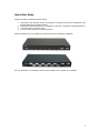
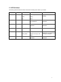
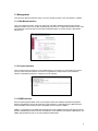
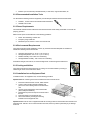
IntraCore™ 65120 Series
Gigabit Ethernet Switches
User’s Manual
Quick Start Guide
Follow these steps to install the IntraCore 65120:
1.
2.
3.
4.
Open the box and check the contents. See Chapter 2.1 Package Contents for a complete list of the
items included with your IntraCore 65120.
Install the IntraCore 65120 switch in an equipment or wall rack, or prepare it for desktop placement.
Connect the power cord to the switch.
Connect network devices to the IntraCore 65120.
Refer to Chapters 3 and 4 to configure the IntraCore 65120 for management capabilities.
For more information on installing the IntraCore 65120, please refer to Chapter 2.2 Installation.
2
IntraCore™ 65120 Series
Gigabit Ethernet Switches
User’s Manual
Asanté Technologies, Inc.
821 Fox Lane
San Jose, CA 95131
USA
SALES
800-662-9686 Home/Office Solutions
800-303-9121 Enterprise Solutions
408-435-8388
TECHNICAL SUPPORT
801-566-8991 Worldwide
801-303-3787 FAX
www.asante.com
[email protected]
Copyright © 2001 Asanté Technologies, Inc. All rights reserved. No part of this document, or any associated
artwork, product design, or design concept may be copied or reproduced in whole or in part by any means
without the express written consent of Asanté Technologies, Inc. Asanté is a registered trademark and the
Asanté logo and IntraCore are trademarks of Asanté Technologies, Inc. All other brand names or product
names are trademarks or registered trademarks of their respective holders. All features and specifications
are subject to change without prior notice.
57-10027-00 Rev. A
3
Table of Contents
Quick Start Guide
2
Chapter 1 Introduction
6
1.1 Front Panel Descriptions
1.2 LED Definitions
1.3 Management
Chapter 2 Installation and Setup
2.1 Package Contents
2.2 Installation Overview
2.3 Setup
2.4 Password Protection
2.5 IP Assignment
2.6 SNMP Host Access
Chapter 3 Web-Based Management
3.1 Web Pages
3.2 Introduction
3.3 System Manager
3.4 Port Manager
3.5 Address Manager
3.6 Spanning Tree
3.7 VLAN Setup
3.8 Port Trunking
3.9 Port Mirroring
3.10 SNMP (Simple Network Management Protocol) Management
3.11 IGMP (Internet Group Management Protocol) Management
3.12 Statistics
Chapter 4 Console Interface
4.1 User Interface
4.2 Characteristics
4.3 Main Menu
4.4 System Manager
4.5 Port Manager
4.6 Address Manager
4.7 Spanning Tree
4.8 VLAN Setup
4.9 Port Trunking
4.10 Port Mirroring
4.11 Simple Network Management Protocol (SNMP) Management
4.12 Internet Group Management Protocol (IGMP) Management
4.13 Statistics
6
7
8
10
10
10
12
13
14
15
16
16
17
17
20
20
21
22
23
24
24
26
26
28
28
28
28
29
31
31
32
33
33
34
34
35
35
Chapter 5 Firmware Update Procedure
36
Chapter 6 Switching Concepts
37
6.1 Spanning Tree Protocol
6.2 Full Duplex, Flow Control and Auto-negotiation
37
38
Appendix A: Troubleshooting
40
Appendix B: VLAN Description and Examples
41
Appendix C: Features, Defaults and Specifications
44
4
Appendix D: FCC Compliance and Safety Statements
46
Appendix E: Online Warranty Registration
47
5
Chapter 1 Introduction
Thank you for purchasing the Asanté IntraCore 65120 Series Gigabit Ethernet switch. In addition to the
traditional console and telnet interface, this switch can also be configured and managed through a userfriendly web browser interface. With an on-board HTTP server, users can access the box with the use of
popular browsers such as Netscape Navigator and Microsoft I.E (Netscape Navigator 4.0 and IE 4.01 or
higher required). The IntraCore 65120 also supports firmware updates using the TFTP protocol.
This manual is designed for System Administrators, Information Technologies Professionals, and other
users who are familiar with the setup and operation of managed networks. This chapter describes the
functional overview of the Gigabit Ethernet switch:
•
•
•
Front/Rear Panel Description
LED Definitions
Management
1.1 Front Panel Descriptions
The front panel contains all the Ethernet ports, Console port, and LEDs. There is one System LED, four
LEDs for each copper port (model 65120-2G only), and one LED for each GBIC port. Detailed definitions
can be found Table 1-1.
Figure 1-1: 65120-2G
Figure 1-2: 65120-12G
6
1.2 LED Definitions
The following Table describes the LEDs, which allows monitoring of the status of your switch:
Port
N/A
LED
Color
Power/System Green
ON
Power is up
Amber
Booting
OFF
Power is off or system is
initializing
10/100/1000
1G Link
Red
Green
Failure
A valid 1000 Mbps link has
been established
No 1000 Mbps link has been
established
10/100/1000
10/100 Link
Green
A valid 10/100 link has been
established
No 10/100 Mbps link has been
established
10/100/1000
Activity
Blinking Green
Traffic detected
No traffic detected
10/100/1000
FDX/HDX
Solid Green
Full Duplex
Blinking Green
Collisions occurring in halfduplex
No Full Duplex link has been
established, or no collisions are
occurring in half-duplex
Green
A valid link has been
established
GBIC
Link
No GBIC link has been
established
Table 1-1 LEDs
7
1.3 Management
There are three different methods by which a user can manage the switch: web, console/telnet, or SNMP.
1.3.1 Web-Based Interface
Users can configure the switch, monitor the LED panel, and display statistics graphically with Netscape
Navigator browser version 4.0 or higher and Microsoft IE version 4.01 or higher. With Internet access, users
can link directly to the local switch’s home page. Detailed description is found in Chapter 3 Web-Based
Management.
1.3.2 Console Interface
Users can also access the switch in a more traditional way by connecting a PC or terminal to the console
port or by telnet across the network. The menus are organized in a manner similar to the web-based
interface. A detailed description is in Chapter 4 Console Interface.
1.3.3 SNMP Interface
Since the switch supports SNMP, users can manage the switch with an SNMP-compatible management
station running platforms such as HP OpenView. It also supports a comprehensive set of MIB extensions
along with MIB II, Ethernet MIB, the 802.1d bridge MIB, and the 4 groups of RMON.
SNMP v.1 is implemented. The SNMP agent decodes the incoming SNMP messages and responds to these
requests with MIB objects that are stored in the database. For the statistics and counters of MIB Objects, the
SNMP agent periodically (every 5 seconds) updates the MIB Objects.
8
1.3.4 Management Information Bases (MIBs)
The system supports the following MIBs:
1. MIB II (RFC 1213)
2. Ethernet Interface MIB (RFC 1643)
3. Bridge MIB (RFC 1493)
4. 4 groups of RMON (RFC 1457)
• The Ethernet Statistics Group
• The Ethernet History Group
• The Alarm Group
• The Event Group
5. Enterprise MIB
• CommGroup: Allows users to configure the community database
• HostGroup: Allows users to configure the hosts
• MiscGroup: Allows users to configure miscellaneous items
• SpanGroup: Allows users to configure the Spanning Tree
• ConfigGroup: Allows users to configure the system
9
Chapter 2 Installation and Setup
This chapter provides the following information:
•
•
•
•
•
•
Package Contents
Installation
Setup
Password Protection
IP Assignment
SNMP Host Access
2.1 Package Contents
The IntraCore 65120 package contains the following:
•
•
•
•
•
•
IntraCore 65120 Series Gigabit Ethernet switch
Getting Started Guide (printed)
Power Cord
Self-adhesive rubber feet for desktop placement
Rack mount kit for rack installation
IntraCore 65120 CD-ROM with user’s manual, utilities and product information
If any of these items are missing, contact your dealer immediately.
2.2 Installation Overview
The switch may be installed into an equipment or wall rack, or it may be placed on a level and stable
desktop surface.
The following guidelines will help you prepare to install the switch in such a way that it has the proper power
supply and environment.
2.2.1 Safety Overview
The following information provides safety guidelines to ensure your safety and to protect the switch
from damage.
Note: Be aware, however, that this information is intended as a guideline, and may not include every
possible hazard to which you may be exposed. Use caution when installing this switch.
•
•
•
•
•
Only trained and qualified personnel should be allowed to install or replace this equipment.
Always use caution when lifting heavy equipment
Keep the unit clean
Keep tools and components off the floor and away from foot traffic
Avoid wearing rings or chains (or other jewelry) that could get caught in the switch. Metal objects
can heat up and cause serious injury to persons and damage to the equipment. Avoid wearing
loose clothing (i.e. ties or loose sleeves)
When working with electricity, follow these guidelines:
•
•
•
•
•
Before accessing the interior of the switch, locate the emergency power-off switch for the room you
are in
Disconnect all external cables before installing or removing the cover
Do not work alone when working with electricity
Always check that the power has been disconnected from the circuit
Do not tamper with the equipment
10
•
Examine your work area for potential hazards (I.e. wet floors, ungrounded cables, etc.
2.2.2 Recommended Installation Tools
You will need the following tools and equipment (not included) to install the IntraCore 65120 switch:
•
•
Number 1, number 2 and 3/16-inch flat-blade screwdrivers
Antistatic mat or foam
2.2.3 Power Requirements
The electrical outlet should be located near the IntraCore 65120 and be easily accessible. It must also be
properly grounded.
Make sure the power source adheres to the following guidelines:
•
•
•
Power: Auto Switching 110/240 VAC
Frequency range: 50/60 Hz
Maximum input AC Current: 1.0A at 115 VAC full load
2.2.4 Environmental Requirements
The IntraCore 65120 must be installed in a clean, dry, dust-free area with adequate air circulation to
maintain the following environmental limits:
•
•
•
•
Operating Temperature: 0° to 40° C (32° to 104° F)
Storage Temperature: -20° to 70° C (-4° to 158° F)
Relative Humidity: 10% to 90% non-condensing
Storage Relative Humidity: 10% to 95% non-condensing
Avoid direct sunlight, heat sources, or areas with high levels of electromagnetic interference.
2.2.5 Cooling and Airflow
The IntraCore 65120 uses internal fans for air-cooling. Do not restrict airflow by covering or
obstructing air vents on the sides of the switch.
2.2.6 Installation into an Equipment Rack
To install the unit in an equipment rack, use the following procedure:
Important! Before continuing, disconnect all cables from the IntraCore 65120.
1.
2.
3.
4.
5.
6.
Place the IntraCore 65120 on a flat, stable surface.
Locate a rack-mounting bracket (supplied) and
place it over the mounting holes on one side of the
unit.
Use the screws (supplied) to secure the bracket
(with a Phillips screwdriver).
Repeat the two previous steps on the other side of
the unit.
Place the switch in the equipment rack.
Secure the switch by securing its mounting
brackets onto the equipment rack.
Important! Make sure the unit is supported until all the mounting screws for each bracket are secured to the
equipment rack. Failure to do so could cause the unit to fall, which may result in personal injury or damage
to the unit.
11
2.2.7 Equipment Rack Guidelines
•
•
•
Size: 17.25 x 10.0 x 1.7 inches
423 x 245 x 43 mm
Ventilation: Ensure that the rack is installed in a room where the temperature remains below 40° C
(104° F). Be sure that there are no obstructions, such as other equipment or cables, blocking
airflow to or from the IntraCore 65120 vents.
Clearance: In addition to providing clearance for ventilation, ensure that there is adequate
clearance for servicing the IntraCore 65120 from the front.
2.3 Setup
The following sections describe the various methods for setting up and managing the switch.
2.3.1 Connecting to a Console or Workstation
When attaching a workstation to the device, a standard straight-through CAT5 cable may be used, even
when the workstation is attached via a patch panel. However, when attaching to another switch or attaching
workstations via hubs, a crossover cable will need to be used. It is recommended that the switch be kept off
the network until proper IP settings have been set.
To connect the switch to a console or computer, setup the system in the following manner:
1.
2.
3.
Plug power cord into the back of unit.
Attach a straight through serial cable between the RS232 port and a COM port on the PC.
Setup a Hyperterminal (or equivalent terminal program) in the following manner:
•
•
•
•
•
•
Choose the appropriate COM port (COM1, COM2, etc)
Set the data rate to 9600 Baud
Set data format 8 data bits, 1 stop bit and no parity
Set flow control to NONE
In setting under Properties, choose VT100 for Emulation mode
Select Terminal keys for Function, Arrow and Ctrl keys. Be sure the setting is for Terminal
keys, NOT Windows keys
Now that terminal is setup correctly, power on the switch (boot sequence will display in terminal).
2.3.2 Connecting Via the Web Browser Interface
To connect to the switch via your web browser, you must first have configured your computer’s IP address to
be on the same IP address subnet as the switch (192.168.0.x). For more information on how to configure
your TCP/IP settings, please refer to your computer manufacturer’s user’s manual.
You may now launch your web browser and enter the switch’s default IP address into the address field. The
Introduction page will appear, and you may proceed through the pages to configure each variable. Password
Protection is disabled by default. If this feature is enabled (via console or telnet) without having set your own
password, the default password is Asante. Asante is case sensitive and must appear exactly as it is shown
here. See Chapter 3 Web-Based Management for more information on configuring the switch via your web
browser.
2.3.3 Connecting Via Telnet
To connect to the switch via a telnet session, you must first have configured your computer’s IP address to
be on the same IP address subnet as the switch (192.168.0.X). For more information on how to configure
your TCP/IP settings, please refer to your computer manufacturer’s user’s manual.
You may now run a telnet session to configure and manage your switch. The Main Menu will appear (unless
you have enabled the Password Protection feature), allowing you to select the variables that you wish to
configure. See Chapter 4 Console Interface for more information on configuring the switch via telnet.
12
2.4 Password Protection
The Password Protection feature is disabled by default, allowing immediate access to ANYONE on the
network. To protect your switch from unauthorized changes to the configuration, you must enable the
protection feature. It can only be enabled through the console interface.
To set a password via telnet, follow these steps:
Note: Use the arrow keys to move within a menu. Press Enter to proceed, and press the Esc. Key to return
to the previous screen. Use the spacebar to toggle between highlighted choices. Please refer to Chapter 4.2
for more detailed description of the common keystrokes used within the menus.
1.
From the Main menu, use the arrow keys to select a. System Manager and press Enter.
2.
Select c. Security Administration.
3.
Use the arrow keys to highlight a field. Press the spacebar to enable Password Protection.
13
4.
5.
6.
Now enter your password, pressing Enter when done.
Enter the password again to confirm, pressing Enter when done.
Press Ctrl+W to save.
2.5 IP Assignment
To assign an IP address (other than the default IP address):
1.
2.
From the Main Menu, select a. System Manager.
Select b. IP address.
3.
In the first field enter the proper IP address for this system (consult your network administrator).
4.
5.
Enter the address of the default gateway for the network to which the switch is attached.
Finally enter the appropriate network mask for this network (again consult your network
administrator).
14
6.
7.
8.
Press Ctrl-W when done to save these changes.
After making IP changes, the system needs to be reset. Press the Esc key to return to the System
Manager Menu.
Go to System Manager/Reset. Use the arrow keys to select Yes to proceed with Reset.
2.6 SNMP Host Access
When the reset is complete the box should be seen on the network. If not, check the IP information again
with your network administrator to ensure that all the data is correct. By default, any PC on the network can
manage the switch via the Web Interface. However, if this is not desired, you may enable Host
Authorization, allowing only hosts that are listed in the SNMP Host Table to access the box.
Follow these steps to configure Host Access:
1.
2.
Choose a. System Manager from the Main Menu.
Next choose h. SNMP Management.
3.
4.
Select Host Table by using the arrow keys and pressing Enter.
Enter the host name and IP address. Repeat this for as many hosts as necessary. Enter Web
Interface for the community string. Press the spacebar when Disabled is highlighted. The status will
change to Active.
When done entering hosts, press Ctrl+W to save this data.
5.
For other management tasks, please refer to Chapters 3 and 4. To review switching concepts, please refer
to Chapter 6.
15
Chapter 3 Web-Based Management
Web-Based Management allows switch configuration changes to be made using an Internet Web browser.
This interface also allows for system monitoring of the Switch.
Buttons featured are:
•
•
Reload: Pulls that screen’s data from current
values on the system
Apply: Submits change request to system and
refreshes screen data
Please refer to Chapter 6 Switching Concepts to review any features that are not familiar to you.
3.1 Web Pages
Connect to the switch through your web browser (i.e. Netscape Navigator) by using the default IP address
192.168.0.1. A login screen will appear prompting for an administrator password (only if the password is
enabled). The User Name will always be root. Enter the password to access the switch’s management
mode. Once the password is entered correctly, the front page will appear.
Note: Password protection is optional and can only be enabled through the console interface. If the
password protection is enabled without having set your own password, the default password is Asante.
Asante is case sensitive and should be entered exactly as shown.
There are eleven menu options available:
•
•
•
•
•
•
•
•
•
•
•
Introduction
System Manager
Port Manager
Address Manager
Spanning Tree
VLAN Setup
Port Trunking
Port Mirroring
SNMP Management
IGMP Management
Statistics
16
3.2 Introduction
This page briefly describes the web-based management features, device management and Interface
operation. It contains a product overview and product features.
3.3 System Manager
The system manager contains all system operations and general information. It is organized with several
sub-folders:
•
•
•
•
•
General Info: General system information and administration
IP Settings: IP parameters
NVRAM Admin: Save configuration or reset to factory defaults
Firmware Update:TFTP the latest firmware for update
Reset: Reset the switch
3.3.1 General Info
The following fields are accessible under the general info page:
•
•
•
•
•
System Description
System Name
System Contact
System Location
MAC Address
The Media Access Control (MAC) address and the System Description are not configurable.
17
3.3.2 IP Settings
There are three tunable parameters to be set by the system administrator:
•
•
•
Enter site-specific IP address, Gateway address and Network mask
Click Apply to change the IP settings
Save Configuration to NVRAM and reset the system to implement the changes
3.3.3 NVRAM Admin
After making any changes to the screens within the Web Interface, users must save the changed settings to
Non-Volatile Random Access Memory (NVRAM). This is done in the system administration screen in order
for the new settings to remain after a system reboot.
Save Configuration to NVRAM
•
Click on the Save button to save configuration to NVRAM
Restore Defaults
•
Click on Restore Defaults to reset the switch’s parameters to their original default settings. In
order for changes to occur, you must reset the switch.
Note: Network IP settings (i.e. IP address, Gateway Address, Network Mask) will not be affected by
this command.
Restore Defaults without Boot Parameters
•
Click on Restore Defaults without Boot Parameters to reset MOST of the switch’s parameters,
but leaves the IP address information and the boot loader configuration alone, so that the switch is
still up and manageable.
18
3.3.4 Firmware Update
On the Firmware Update screen, the system can be configured to download and boot from a new image off
the network (Please refer to Chapter 5 when updating software). Choose from the following options:
Net option:
This option allows the user to try out a new image before upgrading. It requires a TFTP server and a server
IP address to retrieve the specified image from the given IP address. The new image will not overwrite the
one in the flash (This option is the default setting.).
Net & save option:
This option requires the same setup as the Net option, i.e. TFTP server and a new image. However, it
copies the image to the flash directly and the system boots from the flash afterwards.
Last Saved option:
This option will automatically show up after the Net & save option is selected and the unit is reset. Save the
configuration to NVRAM and reset the switch. The image will load automatically after the switch resets.
Enter the TFTP Server IP Address and Filename information in the appropriate fields.
3.3.5 Reset
In this screen the user can reset the switch. This is primarily used to update the firmware or restore defaults.
19
3.4 Port Manager
This page will allow access to the port parameters. The configurable parameters are available as follows:
•
•
•
•
•
•
Port Name
Port Enable
Auto Negotiation
Operating Parameters
Flow Control
HOL Blocking
3.5 Address Manager
The Address Manager allows you to add or remove static address entries as well as change the dynamic
address aging times.
3.5.1 Static Addresses
Any system whose MAC address and the port number are listed in this screen will not be purged from the
system’s forwarding table by the Aging process.
Add a new entry:
•
•
Enter the MAC address and port in the appropriate boxes (You must enter the MAC address in the
form XX:XX:XX:XX:XX:XX)
Click Add
20
Remove an existing entry:
•
•
Highlight that entry in the table, by clicking on the MAC address
Choose Remove
3.5.2 Address Aging
Aging Time is a variable that must be configured. Its purpose is to determine the amount of time an entry is
held in the forwarding tables.
The default value is set to 300 seconds (5 minutes).
•
•
The administrator may change this value to any value between 10 and 1,000,000 seconds
After changing the value, click Apply
3.6 Spanning Tree
Spanning Tree can be enabled or disabled in this screen (it is enabled by default).
3.6.1 Bridge Settings
Enable: There are four other tunable parameters to be addressed.
•
•
•
•
Hello Time: Interval between configuration messages sent by the spanning tree algorithm
Max Age: Amount of time before a configuration message is discarded by the system
Forward Delay: Amount of time system spends in “learning” and “listening” states
Bridge Priority: Priority setting among other switches in the spanning tree
Disable: Disable spanning tree algorithm on the system.
Click Apply after setting your parameters.
21
3.6.2 Port Settings
For the Port Settings options, you can specify spanning tree parameters for each port. These parameters
include port priority and path cost.
3.7 VLAN Setup
The VLAN tagging option is a standard set by the IEEE to facilitate the spanning of Virtual Local Area
Networks (VLANs) across multiple switches (Reference: IEEE standard 802.1Q-1998 Virtual Bridged Local
Area Networks).
This page has two options: Membership and PVID Settings.
3.7.1 Membership
The VLAN Membership option allows users to define VLAN groups. Under the Show VLAN pull-down
menu, the Add a new VLAN option will create a new VLAN.
Add VLAN Group:
•
•
•
Click on the Add a new VLAN under the Show VLAN menu
Enter the VLAN ID and name under the Add a new group option
Click Apply
Remove VLAN Group:
•
•
•
Select the VLAN you want to remove from the Show VLAN menu
Check the Remove VLAN
Click Apply
22
Add VLAN Membership:
•
•
Select the VLAN you want to modify
Click the box below the port number on the line of the VLAN, so that a “T” (tagged) or “U”
(untagged) appears
Remove VLAN Membership:
•
Click the box again until a blank box appears. This will remove VLAN membership from the port
3.7.2 Port VLAN ID (PVID) Settings
All untagged packets entering the switch will by default be tagged with the ID specified by the port’s PVID.
This screen allows you to specify the PVID for each port (the PVID range is 1 – 4094).
3.8 Port Trunking
Note: Please make sure that Spanning Tree is disabled before you set up Port Trunking.
Port Trunking is a feature that allows multiple links between switches to work as one virtual link or aggregate
link. Trunks can be defined for similar port types only. For example, a 10/100 port cannot form a port trunk
with a gigabit port. For 10/100 ports, trunks can only be formed within the same cluster. A cluster is a set of
eight ports.
23
3.9 Port Mirroring
Port mirroring is a feature to help in the debugging of a network. This web interface page allows enabling or
disabling of port mirroring and the setting of source and monitor ports. The Monitor port will show a copy of
every packet that arrives or leaves the source port.
3.10 SNMP (Simple Network Management Protocol) Management
The SNMP menu contains the following sub-menus:
•
•
•
Community Table
Host Table
Trap Settings
3.10.1 Community Table
In the Community Table the administrator can create different community strings with customized access by
choosing combinations of GET, SET and TRAP rights. Click Apply after you’ve entered the new
parameters.
24
3.10.2 Host Table
The SNMP Host Table screen allows you to add and remove hosts from access rights that have been
granted to community groups. The permissions GET, SET and TRAP are assigned to a community name
and then these permissions are assigned to individual machines by adding those machines and their IP
address to the appropriate community string. Host Authorization can be enabled or disabled.
3.10.3 Trap Settings
The SNMP Trap Setting allows for the enabling or disabling of authentication traps:
•
•
Enable: The system will generate a SNMP trap upon a host authorization failure
Disable: Authentication traps will not be generated
All hosts in communities with TRAP privileges will be notified when a trap condition occurs.
25
3.11 IGMP (Internet Group Management Protocol) Management
IGMP is the Internet control protocol used by IP hosts to report their multicast group memberships to any
neighboring multicast router. Enable IGMP to achieve automatic multicast filtering for efficient bandwidth
utilization.
3.12 Statistics
The statistics page allows the administrator to chart different system data. There are three options on this
page:
•
•
•
Comparison Chart
Group Chart
History Graph
All charts have a maximum ceiling of 2 31 –1. Click on any line or bar on the charts to see its value.
3.12.1 Comparison Chart
This chart allows you to look at all of the ports and graph information on one type of statistic. There are three
parameters to set: Statistic, Refresh Rate and Color.
•
•
•
Statistics: The type of system data to be monitored
Refresh Rate: The time interval between automatic refreshes
Color: The color setting for the chart
When all of the variables are set, click Draw.
26
3.12.2 Group Chart
This chart tracks the types of errors that have occurred on one port. Enter the port selection, the refresh rate
and the color.
When all of the variables are set, click Draw. Click Reset to start again.
3.12.3 History Graph
This page will graph data over time, allowing you to compare each port’s activity. Select the type of data to
monitor. Choose a color for each port and click Add to include that port in the graph. Click Draw when all
the desired ports are entered. To remove a port from the graph, highlight the correct line and click Remove.
27
Chapter 4 Console Interface
The console, using VT100 terminal emulation, can be accessed from the RS232 serial port or a telnet
connection. The switch offers password protection for this interface. All of the following examples of the
Console’s User Interface show a screen capture from a telnet session.
When attached to the User Interface via a telnet session, make sure that your telnet application is configured
to use VT100 emulation.
Please refer to Chapter 6 Switching Concepts to review any features that are not familiar to you.
4.1 User Interface
The switch offers a menu-driven interface. The initial welcome screen requires a password entry in order to
proceed. If there is no password set on the system, the Main Menu will be displayed and access is granted
immediately. By default, password protection is disabled. If enabled, the default password is Asante. To
enable password protection, see Chapter 2.4.
Note: Asante is case sensitive and must appear exactly as it is shown here.
4.2 Characteristics
There are several characteristics to the User Interface pages that are necessary to know before proceeding
to use it. The arrow keys may be used to move within menus and sub-screens. At the bottom of every
screen are some key commands available to the user for that particular screen, as well as some helpful
information. The common keystrokes and their definitions and intricacies are listed below:
•
•
•
•
•
•
•
ESC
Ctrl-L
Ctrl-D
Ctrl-W
Spacebar
Enter
Ctrl-X
Return to the previous menu or screen, or abort editing
Refresh the screen
Log off
Saves current configuration to NVRAM
Toggles between possible settings for a field
Select a menu item, edit a field, or accept a value after editing a field
Delete a table entry
4.3 Main Menu
The main menu displays all the sub-menus that are available. By pressing Enter at a highlighted option you
will confirm the choice of the specified sub-menu. There are ten menu items to choose from:
•
•
•
•
•
•
•
•
•
•
System Manager
Port Manager
Address Manager
Spanning Tree
VLAN Setup
Port Trunking
Port Mirroring
SNMP Management
IGMP Management
Statistics
To log out of the user interface, press Ctrl+D at anytime during your telnet session. You will be brought back
to the login screen.
28
4.4 System Manager
This menu contains all the options needed for basic configuration of the switch. Menu items are:
•
•
•
•
•
•
General Info
IP Settings
Security Admin
NVRAM Admin
Firmware Update
Reset
4.4.1 General Info
This screen displays the following:
•
•
•
•
•
System Description
System Name- user definable
System Contact-user definable
System Location-user definable
MAC Address
4.4.2 IP Settings
This menu manages the IP related information of the
system.
•
•
Enter a site-specific IP address, Gateway
Address, and Network Mask (or subnet mask).
Consult your network administrator for the
information
Press Ctrl+W to save any changes made
4.4.3 Security Admin
This screen allows the user to setup the following security features:
•
•
Web access—The web browser interface is
disabled by default. Use the arrows on the
keyboard to highlight this field and press the
spacebar to enable this feature.
Password Protection—Anyone on the network
can access the switch via telnet until you’ve
enabled the password protection feature.
Highlight this field and press the spacebar to
enable this feature. Enter your new password,
enter it again to verify, and press Ctrl+W to
save your changes.
29
4.4.4 Non-Volatile Random Access Memory (NVRAM) Admin
This screen allows the user to save any configuration
changes that are made, or to restore the default
settings (choosing Restore Defaults without Boot
Parameters will reset most defaults, but not the IP
address and boot loader configuration). Highlight the
desired choice and press Enter. Select Yes to
confirm. You may also save any changes to NVRAM
at each sub-menu by pressing Ctrl+W and selecting
Yes to confirm.
4.4.5 Firmw are Update
This screen allows users to select an image file and the location from where it can be downloaded using
TFTP. There are three options: Net, Net & Save, and Last Saved (Please refer to Chapter 5 when updating
software.).
•
•
•
Net option—This option allows the user to try
out a new image before upgrading. It
requires a TFTP filename and a server IP
address to retrieve the specified image from
the given IP address.
Net & Save option—This option requires the
same setup as the Net option, i.e. TFTP
server and a new image. However, it copies
the image to the flash directly and the
system reboots from the flash afterwards.
Last Saved option—This option will
automatically take effect after the Net & Save option is selected and the unit is reset.
Note: The previous image in the flash will be lost when the procedure completes.
4.4.6 Reset
To reset the switch to its original default settings,
select Reset from the System Manager menu. Select
Yes to proceed, and press Enter.
30
4.5 Port Manager
The Port Manager screen allows the user to arrange the port characteristics related to link operations. Select
a. All Ports to arrange multiple port configurations, or b. Port Specific to configure one port at a time. Use the
spacebar to toggle between selections.
4.5.1 All Ports
From the All Ports screen, the following characteristics
can be configured:
•
•
•
•
•
Admin field: Allows Administrator to Enable or
Disable the port
Auto-Neg: Allows the Administrator to enable or
disable the auto-negotiation for the port
Duplex field: Offers the choice of Full, Half, or
Auto (will auto-detect the value of the attached
device and set the port duplex accordingly)
Flow Control: Flow control stops the sender
from sending data until the receiver can accept it
Comments: Allows the administrator to name the port or make comments
4.5.2 Port Specific
The options here are similar to those in the All Ports menu. The difference is that only the specified port will
be changed.
The upper half of this screen shows the current status for the following parameters:
•
•
•
•
Link Status
Duplex
Data Rate
Port State
From the Port Specific screen, the following
characteristics can be configured:
•
•
•
•
•
•
•
•
Auto-Negotiation
Data rate
Duplex
Flow Control
Comments
Admin Status
HOL Prevention
Port VLAN ID
4.6 Address Manager
This screen allows the user to configure the Static Bridge Table and to set the Aging time.
4.6.1 Static Addresses
Systems whose MAC address and port number are
listed in this screen will not be purged from the
forwarding table by the Aging process. Enter the
desired MAC Addresses and port numbers and press
Ctrl+W to save your changes.
31
4.6.2 Address Aging
Aging Time is a variable that must be configured. Its
purpose is to determine the length of time an entry is
held in the forwarding tables. The default value is set
at 300 seconds (5 minutes).
The Administrator may change this value to any value
between 10 and 1,000,000 seconds.
4.7 Spanning Tree
Spanning Tree can be enabled or disabled in this screen.
4.7.1 Bridge Settings
Enable: There are four other parameters to set when
Spanning Tree is enabled.
•
•
•
•
Hello Time: Interval between configuration
messages sent by the spanning tree
algorithm
Max Age: Amount of time before a
configuration message is discarded by the
system
Forward Delay: Amount of time system
spends in “learning” and “listening” states
Bridge Priority: Priority setting among other
switches in the spanning tree
Disable: Disable spanning tree algorithm on the system.
4.7.2 Port Settings
On this screen, you can specify spanning tree
parameters for each port. These parameters include
port priority and path cost.
32
4.8 VLAN Setup
The VLAN tagging option is a standard set by the IEEE to facilitate the spanning of VLANs across multiple
switches (Reference: IEEE standard 802.1Q-1998 Virtual Bridged Local Area Networks).
4.8.1 VLAN Administration
In this screen the user can add new VLAN groups by
entering the VLAN ID and name.
4.8.2 VLAN Membership
Here the user can define VLAN groups by marking
each port “T” (tagged) or “U” (untagged). Use the
space bar to select “T” or “U”. Leaving a space blank
will remove VLAN membership from the port.
4.8.3 Port VLAN ID (PVID) Settings
All untagged packets entering the switch will by
default be tagged with the ID specified by the port’s
PVID. This screen allows the user to specify the PVID
for each port.
4.9 Port Trunking
Note: Please make sure that Spanning Tree is
disabled before you set up Port Trunking.
Port Trunking is a feature that allows multiple links
between switches to work as one virtual link or
aggregate link. Trunks can be defined for similar port
types only. For example, a 10/100 port cannot form a
port trunk with a gigabit port. For 10/100 ports, trunks
can only be formed within the same cluster. A cluster
is a set of eight ports.
33
4.10 Port Mirroring
Port Mirroring is a feature to help in the debugging of
a network. This screen allows for the enabling or
disabling of port mirroring and the setting of source
and monitor ports. The monitor port will show a copy
of every packet that arrives or leaves the source port.
4.11 Simple Network Management Protocol (SNMP) Management
This management protocol allows the user to configure the Community Table, Host Table and Trap Settings
for the network.
4.11.1 Community Table
In the Community Table the administrator can create
different community strings with customized access
by choosing combinations of GET, SET and TRAP
rights.
4.11.2 Host Table
The SNMP Host Table screen allows the user to add
and remove hosts from access rights that have been
granted to community groups. The permissions GET,
SET and TRAP are assigned to a community name
and then these permissions are assigned to individual
machines by adding those machines and their IP
addresses to the appropriate community string.
4.11.3 Trap Settings
The SNMP Trap Settings allows for the enabling or
disabling of an authentication trap:
•
•
Enable: The system will generate a SNMP
trap upon a host authorization failure
Disable: The authentication traps will not be
generated
All hosts in community strings with TRAP privileges will be notified when a trap condition occurs.
34
4.12 Internet Group Management Protocol (IGMP) Management
IGMP is the Internet control protocol used by IP hosts
to report their multicast group memberships to any
neighboring multicast router. Enable IGMP to achieve
automatic multicast filtering for efficient bandwidth
utilization.
4.13 Statistics
This screen views the statistics for each port.
35
Chapter 5 Firmware Update Procedure
The application firmware is field-updateable. The update procedure and the required equipment are
described in this chapter.
Note: Once the system is up, it is controlled by an executing application image residing in the flash memory.
No firmware update is possible during this mode. The update can only be done when the system is
resetting. To initiate this sequence, the user must set the boot mode configuration parameter to Boot from
Net during normal operation, and then perform a reset. When the Boot from NET option is set, Bootstrap can
start the system with an image residing on a TFTP server on the network. Be sure that the TFTP server
residing on the network is accessible by the switch.
Note: It is highly recommended, though not necessary, to use a RS232 serial port connection to the switch
during the firmware updating procedure. When using a telnet Session or web interface alone, your
connection to the switch will not be available until the switch has entered forwarding mode. This takes
approximately three minutes. Once completed, the software version should be verified in the Firmware
Update page. If the older version of the software has not been replaced, the unit was unable to reach the
new software and booted from the old “flash” version.
The upgrade procedure is as follows:
1.
2.
3.
4.
5.
6.
Go to System Manager/Firmware Update (in the Web or Console Interface).
Set Boot from Net option during the normal operation.
Verify information such as the IP address for the TFTP Server, Gateway IP address, and the file
name and its path of the new image, and then press the Submit button, in the Web, or Ctrl+W, in
the console interface.
Restart the system with Boot from Net set.
Bootstrap will retrieve the new image then pass control to it.
The system executes the new image.
Note: The previous image in the flash will not be replaced by the new image using this option.
The image in the flash will be over-written if Boot from Net and Save option is selected.
7.
8.
9.
If you decide to upgrade to the new image, go to Firmware Update again. Set Boot from Net and
Save option, and press the Submit button, in the Web, or Ctrl+W, in the console interface.
Restart the system with Boot from Net and Save set.
The new image should over-write the old image in the Flash memory. Verify it by going to the
Firmware Update screen and checking the Software Release information.
36
Chapter 6 Switching Concepts
The following sections provide brief explanations of some of the concepts related to switching. If more
information is required, please refer to networking textbooks, online resources (i.e. www.oreillynet.com) or
your MIS manager.
6.1 Spanning Tree Protocol
The Spanning Tree Protocol (STP) is part of the IEEE 802.1D standard. It provides for a redundant network
without the redundant traffic through closed paths. For example, in a network without spanning tree protocol,
the same message will be broadcast through multiple paths, which may start an unending packet-passing
cycle. This in turn causes a great amount of extra network traffic, leading to network downtime. The STP
reduces a network like this, with multiple, redundant connections, to one in which all points are connected,
but where there is only one path between any two points (the connections span the entire network, and the
paths are branched, like a tree).
6.1.1 How It Works
All of the bridges (a switch is a complex bridge) on the network communicate with each other using special
packets of data called Bridge Protocol Data Units (BPDUs). The information exchanged in the BPDUs allows
the bridges on the network to do the following:
•
•
•
•
•
Elect a single bridge to be the root bridge
Calculate the shortest path from each bridge to the root bridge
Select a designated bridge on each segment, which lies closest to the root and forwards all traffic
to it
Select a port on each bridge to forward traffic to the root
Select the ports on each bridge that forward traffic, and place the redundant ports in blocking states
6.1.2 Spanning Tree Parameters
The operation of the spanning tree algorithm is governed by several parameters. You should attempt to set
these parameters only if you have experience with the 802.1D specification. To set the parameters listed
below, access the Spanning Tree/Bridge Settings screen (console or telnet), or the Spanning Tree/Bridge
Settings page (in the web interface).
Bridge Priority
Setting the Bridge Priority to a low value will increase the likelihood that the current bridge will become the
root bridge. If the current bridge is located physically near the center of your network, you may wish to
decrease the Bridge Priority from its default value of 32768 to make it become the root bridge. If the current
bridge is near the edge of your network, it is best to leave the value of the Bridge Priority at its default
setting.
Hello Time
This is the time period between BPDUs transmitted by each bridge. The default setting is 2 seconds.
Maximum Age
Each bridge should receive regular configuration BPDUs from the direction of the root bridge. If the
maximum age timer expires before the bridge receives another BPDU, it assumes that a change in the
topology has occurred, and it begins recalculating the spanning tree. The default setting for Maximum Age is
20 seconds.
37
Forward Delay
After a recalculation of the spanning tree, the Forward Delay parameter regulates the delay before each port
begins transmitting traffic. If a port begins forwarding traffic too soon (before a new root bridge has been
selected), the network can be adversely affected. The default value for Forward Delay is 15 seconds.
Note: The above parameters (Hello Time, Maximum Age and Forward Delay) are constrained by the
following formula:
(Hello Time + 1) <= Maximum Age <= 2 x (Forward Delay – 1)
In general, reducing the values of these timers will make the spanning tree react faster when the topology
changes, but may cause temporary loops as the tree stabilizes in its new configuration. Increasing the
values of these timers will make the tree react more slowly to changes in topology, but will make an
unintended reconfiguration less likely. All of the bridges on the network will use the values set by the root
bridge. It is only necessary to reconfigure that bridge if you wish to change the parameters.
6.1.3 Spanning Tree Port Configuration
To set the Port Priority and Port Path Cost values for STP, access the Spanning Tree/Port Settings screen
(console or telnet), or the Spanning Tree/Port Settings page (in the web interface).
Port Priority
The port priority is a spanning tree parameter that ranks each port, so that if two or more ports have the
same path cost, the STP selects the path with the highest priority (the lowest numerical value). By changing
the priority of a port, you can make it more, or less, likely to become the root port. The default value is 128,
and the value range is 0 – 255.
Port Path Cost
Port path cost is the spanning tree parameter that assigns a cost factor to each port. The lower the assigned
port path cost is, the more likely that port will be accessed. The default port path cost for a 10 Mbps or 100
Mbps port is the result to the equation:
Path cost = 1000/LAN speed (in Mbps)
Therefore, for 10 Mbps ports, the default port path cost is 100. For 100Mbps ports, it is 10. To allow for
faster networks, the port path cost for a 1000Mbps port is set by the standard at 4.
6.2 Full Duplex, Flow Control and Auto-negotiation
These switching concepts are all related to maintaining a high rate of data transmission necessary for an
efficient network.
6.2.1 Full Duplex
Traditionally, Ethernet has operated in half duplex mode, meaning that a node or workstation could either
send or receive data, but not both simultaneously. Now, with the use of structured wiring using Unshielded
Twisted Pair cabling, and switched Ethernet, a workstation may operate in full duplex mode, sending and
receiving data at the same time. The ability to use full duplex mode can potentially double the basic capacity
of the channel, so that a Fast Ethernet connection may carry up to 200Mbps.
In order to use full duplex, an Ethernet station must have separate channels to send and receive data. UTP
cabling provides this, whereas the older coaxial Ethernet did not. The station must also have a direct
connection to a switched port. A station connected to only a repeater cannot operate in full duplex mode.
Also, it is critical that both ends of the Ethernet link “agree” on whether the link will operate in full or half
duplex. See 6.2.3 Auto-negotiation for more details.
38
6.2.2 Flow Control
With a link operating at a high data rate, a switch may experience occasional limitations in the buffer space
used to store Ethernet frames before forwarding them. In this situation, if the sending station continues to
send frames, the switch will have no option but to discard the frames. This may quickly lead to unacceptable
delays in upper-level protocols.
In order to avoid unnecessarily dropping frames, a switch may implement Flow Control. Flow control is a
feature that allows the switch to recognize when the buffer space is limited, and to send an Ethernet PAUSE
frame to its link partner to cease transmission for a specified period. As with a full duplex link, both ends of
the link must understand flow control for the mechanism to operate properly.
6.2.3 Auto-Negotiation
As discussed above, you need to make sure that both ends of a link agree about the duplex and flow control
settings to be used (as well as the speed of the connection). In even a mid-sized network, making sure that
all the links agree on all these parameters would be too big a job if the network manager had to configure
every connection manually.
To make configuration as automatic as possible, the IEEE has defined standards so that most connections
can be automatically configured by the hardware, without manual intervention. Devices can agree on the
speed, duplex mode and flow control settings for each individual connection. The possible links states are
ranked:
1000Mbps/Full Duplex
1000Mbps/Half Duplex (never used)
100Mbps/Full Duplex
100Mbps/Half Duplex
10Mbps/Full Duplex
10Mbps/Half Duplex
With auto-negotiation, the link partners will configure the link to operate at the highest speed and duplex
state that both support.
Auto-negotiation is supported on IntraCore switches on all UTP ports. GBIC ports operate at 1Gbps only,
and only in full duplex mode, so auto-negotiation is disabled for GBIC ports.
Note: If an Ethernet device that is capable of auto-negotiation is connected to a port that has autonegotiation turned off, the auto-negotiating device will default to half duplex mode. If the port that is not using
auto-negotiation is set to full duplex, the link will have a duplex mismatch, and will so slow that it may be
unusable. If you configure an Ethernet port to operate in full duplex mode, you must also configure the link
partner to operate in full duplex. It is almost always better to let auto-negotiation take care of this for you.
39
Appendix A: Troubleshooting
In the unlikely event your network does not operate properly, follow the troubleshooting tips below:
CHECK YOUR POWER CONNECTION. Is the Power LED on? If not plug the power cord into another
known working AC outlet.
CHECK YOUR NETWORK CABLE. Are the LINK LEDs on? If not, check the cable connections. Are the
connectors seated correctly in each port? Make sure that the correct type of cable is connected to each port.
CHECK YOUR GBIC CONNECTOR. Are the cables inserted correctly? The receiving and transmitting plugs
must be inserted into their respective receptacles correctly in order to establish a link.
40
Appendix B: VLAN Description and Examples
Packets received by the switch will be treated in the following way with regard to the Switch’s VLAN settings:
1.
2.
3.
4.
5.
6.
7.
When an untagged packet enters a port, it will be automatically tagged with the port’s default VLAN
ID tag number. Each port has a default VLAN ID setting that is user configurable (the default setting
is 1). The default VLAN ID setting for each port can be changed in that port’s respective screen in
the Port Specific sub-menu (Port Manager/Port Specific).
When a tagged packet enters a port, the tag for that packet will be unaffected by the default VLAN
ID Setting.
The packet will now proceed to the VLAN specified by its VLAN ID tag number.
If the port in which the packet entered does not have membership with the VLAN specified by the
packets VLAN ID tag, the packet will be dropped. Port VLAN membership settings are changed in
the VLAN Membership page (VLAN Setup/VLAN Membership).
If the port has membership to the VLAN specified by the packet’s VLAN ID, the packet will be able
to be sent to other ports with the same VLAN ID membership.
Packets leaving the switch will be either tagged or untagged depending on the setting specified for
that port’s membership properties.
A ‘U’ for a given port and VLAN will mean that packets leaving the switch from that port and VLAN
will be Untagged. A ‘T’ for a given port and VLAN will mean that packets leaving the switch from
that port and VLAN will be tagged with the respective VLAN ID in which it participated in.
Two examples of VLAN setup will be given. Example 1 will step through a simple two-group VLAN setup.
Example 2 will step through a more elaborate setup illustrating all possible scenarios for a comprehensive
understanding of tagged VLANs. These examples are shown from the Console interface.
Example 1
1.
In the VLAN Administration page, add a new VLAN to the list, shown below as “New” with a VLAN
ID value of 2.
2.
In the VLAN Membership page, use the space bar to toggle matrix until the desired ports are all
members of the selected VLAN.
41
3.
To allow untagged packets to participate in the ‘New’ VLAN, make sure to change the Port VLAN
IDs for the relevant ports. To access the Port VLAN ID page choose c. PVID Settings from the
VLAN Setup menu. Use the space bar to add an ‘X’ indicating which PVID is assigned to which
port.
Example 2
1.
Setup the following VLANs:
2.
Configure the VLAN membership as follows:
3.
Setup the Port VLAN IDs as follows (Note: The Port One PVID is set to 2. This must be done in the
port specific page since there is no VLAN with ID 2):
42
The specific ports shown above have the following Port VLAN ID settings (The Port VLAN ID settings for
each port are configured in their respective Port Specific screen (in the Port Manager Menu) or in the VLAN
Administration page):
Port 01: 2
Port 02: 15
Port 03: 1
Port 04: 1
Port 05: 5
Port 06: 1
Port 07: 1
Port 08: 1
Port 09: 10
Port 10: 1
Port 11: 10
Port 12: 10
The following scenarios will produce results as described below:
1.
If an untagged packet enters Port 4, the switch will tag it with a VLAN tag value of 1. However,
since Port 4 has membership with VLAN ID 5, the packet will be dropped.
2.
If a tagged packet with a VLAN tag value 5 enters Port 4, the packet will have access to Ports 5
and 1. If the packet leaves Port 5 and/or 1, it will be stripped of its tag becoming an untagged
packet as it leaves the switch.
3.
If an untagged packet enters Port 1, the switch will tag it with a VLAN tag value of 2. It will then be
dropped since Port 1 has no membership with VLAN ID 2.
4.
If a tagged packet with a VLAN tag value 10 enters Port 9, it will have access to Ports: 1, 11, and
12. If the packets leave Port 1, they will be tagged with a VLAN ID value of 10. If the packet leaves
Ports 11 or 12, it will leave as an untagged packet.
5.
If a tagged packet with a VLAN tag value 1 enters Port 9, it will be dropped since Port 9 does not
have membership with VLAN ID 1.
43
Appendix C: Features, Defaults and Specifications
The IntraCore 65120 is shipped with the following factory default settings and specifications:
•
•
•
•
•
•
•
•
•
•
•
•
Switching Method: Store-and-forward
System Packets Buffer Size: 1.5MB
MAC Address Table: 8000
Full-Duplex: Standards-based auto-negotiation enabled
VLAN: 64 port-based VLANs, with IEEE 802.1Q tagging
Spanning Tree Protocol: 802.1D, enabled
Priority: 802.1p, 8 levels mapped to 2 queues
RMON: 4 Groups
SNMP: MIB-II, Bridge MIB, RMON MIB
Console Baud Rate: 9600
Password: Asante (default)
IP Address: 192.168.0.1 (default)
The following is a summary of features of the 65120 Series Gigabit Ethernet Switch:
•
•
•
•
•
•
•
•
•
•
•
•
•
•
•
•
•
•
•
•
•
•
Model 65120-12G: 12 1000Base GBIC ports, which supports 802.3z Gigabit Ethernet 1000BaseSX
or LX, and 802.3ab Gigabit Ethernet 1000BaseT
Model 65120-2G: 10 Gigabit Ethernet switched ports with RJ-45 Twisted Pair (TP) connectors,
which supports 10/100/1000BaseT Ethernet. Each port is capable of detecting 10, 100, or
1000Mbps automatically; 2 1000Base GBIC ports, which supports 802.3z Gigabit Ethernet
1000BaseSX or LX, and 802.3ab Gigabit Ethernet 1000BaseT
8K-entry MAC address cache
Back pressure flow control for half-duplex operation
IEEE 802.3x flow control for full duplex operation
IEEE 802.1Q based VLAN
QoS through dual priority and support for IEEE 802.1p
IGMP support
Port Trunking support
Port Mirroring
Hardware assisted RMON statistic collection
Extensive system LED and per port LEDs
Console port (VT100)
Telnet remote login
Web-based management
On-Board HTTP Server
Network boot/software download via TFTP
SNMP-based network management
o MIB ll (RFC1213)
o Ethernet Interface MIB (RFC1643)
o Bridge MIB (RFC1493)
o 4-Group RMON (RFC1757)
o Enterprise private MIB
o IGMP upgradeable
o Manageable by HP Open View
Transparent bridge (IEEE 802.1D)
o Spanning tree protocol
o Hardware assisted address learning
o Auto aging
o Static address entry
Supports a “Store and Forward” switching engine
Multimedia support
An intelligent address recognition mechanism enables forwarding at full wire speed
44
•
•
•
Supports up to 64 virtual LANs
17-inch and standard 1U chassis high
Internal power supply
45
Appendix D: FCC Compliance and Safety Statements
FCC Compliance Statement
This equipment generates and uses radio frequency energy and if not installed and used properly, that is, in
strict accordance with the instructions provided with the equipment, may cause interference to radio and TV
communication. The equipment has been tested and found to comply with the limits for a Class A computing
device in accordance with the specifications in Subpart B of Part 15 of FCC rules, which are designed to
provide reasonable protection against such interference in a residential installation. However, there is no
guarantee that interference will not occur in a particular installation.
If you suspect this equipment is causing interference, turn your Ethernet Switch on and off while your radio
or TV is showing interference, if the interference disappears when you turn your Ethernet Switch off and
reappears when you turn it back on, there is interference being caused by the Ethernet Switch.
You can try to correct the interference by one or more of the following measures:
1. Reorient the receiving radio or TV antenna where this may be done safely.
2. To the extent possible, relocate the radio, TV or other receiver away from the Switch.
3. Plug the Ethernet Switch into a different power outlet so that the Switch and the receiver are on different
branch circuits.
If necessary, you should consult the place of purchase or an experienced radio/television technician for
additional suggestions.
Caution: Do not use a RJ-11 (telephone) cable to connect your network equipment.
Important Safety Instructions
1. Read all of these instructions.
2. Save these instructions for later use.
3. Follow all warnings and instructions marked on the product.
4. Unplug this product from the wall outlet before cleaning. Do not use liquid cleaners or aerosol cleaners.
Use a damp cloth for cleaning.
5. Do not use this product near water.
6. Do not place this product on an unstable cart or stand. The product may fall, causing serious damage to
the product.
7. The air vent should never be blocked (i.e. by placing the product on a bed, sofa, rug, etc). This product
should never be placed near or over a radiator or heat register. This product should not be placed in a builtin installation unless proper ventilation is provided.
8. This product should be operated from the type of power source indicated on the marking label. If you are
not sure of the type of power available, consult your dealer or local power company.
9. This product is equipped with a three-wire grounding type plug, a plug having a third (grounding) pin. This
plug will only fit into a grounding type power outlet. This is a safety feature. If you are unable to insert the
plug into the outlet, contact your electrician to replace your outlet. Do not defeat the purpose of the
grounding type plug.
10. Do not allow anything to rest on the power cord. Do not place this product where persons will walk on
the cord.
11. If an extension cord is used with this product, make sure that the total ampere ratings on the products
into the extension cord do not exceed the extension cord ampere rating. Also make sure that the total of all
products plugged into the wall outlet does not exceed 15 amperes.
12. Never push objects of any kind into this product through air ventilation slots as they may touch
dangerous voltage points or short out parts that could result in a risk of fire or electric shock. Never spill
liquid of any kind on the product.
13. Do not attempt to service this product yourself, as opening or removing covers may expose you to
dangerous voltage points or other risks. Refer all servicing to service personnel.
46
Appendix E: Online Warranty Registration
Before calling Asanté Technical Support, please register your switch online at
www.asante.com/support/registration.html. By doing so, you’ll be entitled to special offers, up-to-date
information and important product bulletins.
47