1
INSTALLATION AND OPERATING INSTRUCTIONS
TAMARRON
HEAT RECIRCULATIVE GAS FIREPLACE
MODEL : TR36 – NG Natural Gas
TR36 – LP Propane
These gas appliances have been tested in accordance
with National Safety Standards, and have been certified
by Intertek for installation & operation as described in
these Installation and Operating Instructions in the
United States.
Check with your local building code agency before you
begin your installation to ensure compliance with local
codes, including the need for “permits” and follow-up
inspections. If any problems are encountered regarding
code approvals, or if you need clarification of any of the
instructions contained here, contact:
ALPINE GAS FIREPLACES
#801-768-8411 / www.alpinefireplaces. com
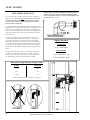
WARNING:
If the information in these
instructions are not followed exactly, a fire or
explosion may result causing property
damage , personal injury or loss of life.
Improper installation, adjustment, alteration,
service or maintenance can cause property
damage, personal injury or loss of life.
FOR YOUR SAFETY
Do not store or use gasoline or other
flammable vapors and liquids in the vicinity
of this or any other appliance.
WHAT TO DO IF YOU SMELL GAS:
• Do not try to light any appliance.
• Do not touch any electrical switch; do
not use any phone in your building.
• Immediately call your gas supplier from
a neighbor’s phone. Follow the gas
supplier’s instructions
• If you cannot reach your gas supplier,
call the fire department.
INSTALLATION AND SERVICE MUST
BE PERFORMED BY A QUALIFIED
INSTALLER, SERVICE AGENCY OR THE
GAS SUPPLIER.
INSTALLER: PLEASE LEAVE THIS MANUAL WITH THE CUSTOMER
HOMEOWNER: PLEASE KEEP THESE INSTRUCTIONS FOR FUTURE REFERENCE
Alpine Gas Fireplaces
782 West State Street
Lehi, Utah 84043
7/04
Tested by:
TABLE OF CONTENTS
GENERAL INFORMATION
Rating Plate........................................ 2
LOG AND EMBER INSTALLATION
Log/Ember Placement………………20/21
Before Starting....................................3
General Safety Information ................3
System Specifications .........................4
Derating the Burner ............................4
GLASS AND LOUVER INSTALLATION
Glass Trim Installation…..………...22
Louver Installation………………...22
OPERATING INSTRUCTIONS
INSTALLATION REQUIREMENTS
Aeration Adjustment……………22/23
Locating the Fireplace ........................ 4
Remote Control/Thermostat……….23
Gas Line Installation........................... 5
Operation Instruction Plate...............24
Clearances........................................... 5
First Fire ...........................................25
Mantel Clearances .............................. 5
Lighting Procedure ...........................25
Hearth Materials ................................. 5
Shutdown Procedure.........................25
Framing and Finishing........................ 6
FIREPLACE MAINTENANCE
Maintenance Instructions ...............25
VENTING
Cleaning the Glass ............................25
Venting Planning ................................ 7
Cleaning the Logs.............................25
Venting Components List................... 7
Cleaning the Valve Chamber............25
Vent Termination Clearances ............. 8
Cleaning Gold /Brass Trims .............25
Horizontal /Vertical Components....... 9
SERVICE
Horizontal Venting Installation ........ 10
Log Replacement..............................26
Vertical Venting .........................10/11
Inspecting the Pilot ...........................26
Horizontal Venting ………….…12-14
Removing/Installing the Valve.........27
Horizontal Installation………….15/16
Replacement Parts List..................... 28
Vertical Installation…………….16/17
Flex Venting……………………….18
TROUBLESHOOTING GUIDE
Gas Control System ......................... 29
WIRING
Blower Wiring .............................19/20
WARRANTY
Millivolt System ............................... 20
Warranty……………………………30
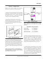
Alpine TR36 Direct Vent Gas Fireplace
1
2
WC
WC
WC
DMS
BTU/h
BTU/h
Ft
Model TR36-LP
Model TR36-NG
Alpine TR36 Direct Vent Gas Fireplace
Minimum supply pressure
11”
Manifold pressure high
10.0”
Manifold pressure low
6.4”
Orifice Size
# 52
Minimum input
25,000
Maximum input
33,000
Altitude
2500 – 6500
WC
WC
WC
DMS
BTU/h
BTU/h
Ft
PROPANE : TAMARRON TR36-LP
Made in USA
Field Converted
Alpine Gas Fireplaces
Lehi, Utah
VENTED GAS FIREPLACE HEATER NOT FOR USE WITH SOLID FUEL.
Use Only Simpson Dura-Vent GS System . Use only Simpson vent cap #0991 on vertical applications. This appliance must be installed in accordance
with the manufacturer’s installation instructions and with local codes, if any; if not, follow the current ANSI Z223.1 in the USA.
This vented gas fireplace heater is not for use with air filters.
Electrical supply 120VAC, 3.5 Amps, 60Hz.
This appliance is only for use with the type of gas indicated on the rating plate and may be installed in an aftermarket, permanently located
manufactured home (USA only) or mobile home, where not prohibited by local codes. See owner’s manual for details. This appliance is not convertible
for use with other gases, unless a certified kit is used.
This appliance approved for bedroom installations.
Minimum supply pressure
4.5”
Manifold pressure high
3.5”
Manifold pressure low
2.2”
Orifice Size
# 40
Minimum input
23,000
Maximum input
31,000
Altitude
2500 – 6500
NATURAL GAS : TAMARRON TR36-NG
Listed:
DIRECT VENT GAS FIREPLACE HEATER
Tested to: ANSI Z21.88a-2003/CSA2.33a-2003
VENTED GAS FIREPLACE HEATER.
Report No. 3060953 (Jun.04)
Serial Number: TAMARRON TR36-
DO NOT REMOVE THIS LABEL
This appliance may be recessed until
the front of the unit is flush with any
combustible facing material. Non
combustibles may overlap.
1 1/2” Clearance to Vertical Pipe
Flue clearances are as follows:
Horizontal Pipe
2” to combustibles – Top
1” to combustibles – Sides
1/2” to combustibles – Bottom
This appliance must be installed in
accordance with the following
minimum clearances:
2” to combustibles – Top
1/2” to combustibles – Sides
1” to combustibles – Back
0” to combustibles – Bottom
18” from top of stove – Ceiling
24” from top of stove-Ceiling (flex)
6” to combustible Mantel projecting 6”
from wall. Add 1” of height for every 1”
of projection after the 6” minimum.
GENERAL INFORMATION
GENERAL INFORMATION
IMPORTANT:
SAVE THESE INSTRUCTIONS
The TR-36 Direct Vent Fireplace must be installed in
accordance with these instructions. Carefully read all
the instructions in this manual first. Consult the
“authority having jurisdiction” to determine the need
for a permit prior to starting the installation. It is the
responsibility of the installer to ensure this fireplace is
installed in compliance with the manufacturer’s
instructions and all applicable codes.
BEFORE YOU START
Safe installation and operation of this appliance
requires common sense, however, we are required by
ANSI Standards to make you aware of the following:
INSTALLATION AND REPAIR SHOULD BE
DONE BY A QUALIFIED SERVICE PERSON.
THE APPLIANCE SHOULD BE INSPECTED
BEFORE USE AND AT LEAST ANNUALLY BY
A PROFESSIONAL SERVICE PERSON. MORE
FREQUENT CLEANING MAY BE REQUIRED
DUE TO EXCESSIVE LINT FROM
CARPETING, BEDDING MATERIAL, ETC. IT
I S IM P ER A T IV E T H A T CO N T RO L
COMPARTMENTS,
BURNERS
AND
CIRCULATING AIR PASSAGEWAYS OF THE
APPLIANCE BE KEPT CLEAN.
DUE TO HIGH TEMPERATURES, THE
APPLIANCE SHOULD BE LOCATED OUT OF
TRAFFIC AND AWAY FROM FURNITURE
AND DRAPERIES.
WARNING: FAILURE TO INSTALL THIS
APPLIANCE CORRECTLY WILL VOID YOUR
WARRANTY AND MAY CAUSE A SERIOUS
HOUSE FIRE.
CHILDREN AND ADULTS SHOULD BE
ALERTED TO THE HAZARDS OF HIGH
SURFACE TEMPERATURES, ESPECIALLY
THE FIREPLACE GLASS, AND SHOULD STAY
AWAY TO AVOID BURNS OR CLOTHING
IGNITION.
YOUNG
CHILDREN
SHOULD
BE
CAREFULLY SUPERVISED WHEN THEY ARE
IN THE SAME ROOM AS THE APPLIANCE.
CLOTHING OR OTHER FLAMMABLE
MATERIAL SHOULD NOT BE PLACED ON
OR NEAR THE APPLIANCE.
GENERAL SAFETY INFORMATION
1) The appliance installation must conform with
local codes or, in the absence of local codes, with
the current National Fuel Gas Code, ANSI
Z223.1 installation code.
2) The appliance when installed, must be electrically
grounded in accordance with local codes, or in
the absence of local codes with the current
National Electrical Code, ANSI/NFPA 70.
3) This appliance must be connected to the specified
vent and termination cap to the outside of the
building envelope. Never vent to another room or
inside a building. Make sure that the vent is fitted
as per venting instructions.
4) Inspect the venting system annually for blockage
and any signs of deterioration.
5) Venting terminals shall not be recessed into a
wall or siding.
6) Any safety glass removed for servicing must be
replaced prior to operating the appliance.
7) To prevent injury, do not allow anyone who is
unfamiliar with the operation to use the fireplace.
8) Wear gloves and safety glasses for protection
while doing required maintenance.
9) Be aware of electrical wiring in locations in walls
and ceilings when cutting holes for termination.
10) Under no circumstances should this appliance be
modified. Parts that have been removed for
servicing should be replaced prior to operating
this appliance.
11) Installation and any repairs to this appliance
should be done by a qualified service person. A
professional service person should be called to
inspect this appliance annually. Make it a practice
to have all of your gas appliances checked
annually.
12) Under no circumstances should any solid fuels
(wood, paper, cardboard, coal etc.) be used in this
appliance.
13) The appliance area must be kept clear and free of
combustible materials, gasoline and other
flammable vapors and liquids.
14) If the pilot goes out for any reason, turn the
control knob to the off position. Wait five
minutes before attempting to re-light pilot.
15) Never obstruct the flow of ventilation and
combustion air to the fireplace.
Alpine TR36 Direct Vent Gas Fireplace
3
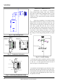
GENRAL INFORMATION/INSTALLATION REQUIREMENTS
SYSTEM SPECIFICATIONS
LOCATING THE FIREPLACE
Burner Inlet Orifice Sizes:
(2500 TO 6500 feet altitude )
Natural Gas: #40
Propane: #52
1) When selecting a location for your Gas Fireplace,
ensure that the clearances outlined in this manual are
adhered to strictly.
Max. Input Rating –
Natural Gas
Propane
31,000 Btu/h
33,000 Btu/h
2) Ensure that the Positive Pressure Blower will be
accessible for post-installation maintenance.
Min. Input Rating –
Natural Gas
Propane
23,000 Btu/h
25,000 Btu/h
Min. Supply Pressure
Natural Gas
Propane
4.5” w.c.
11.0” w.c.
3) The fireplace must be installed on a flat, solid,
continuous surface. If the appliance is to be raised
off the floor on a platform, it must be securely
fastened to a sturdily constructed platform.
Natural Gas
Propane
8.0” w.c.
13.0” w.c.
Max. Supply Pressure
Manifold Pressure
Natural Gas
Propane
3.5” +/-0.2” w.c.
10” +/-0.2” w.c.
4) If the appliance is to be installed on carpeting,
combustible vinyl tiling, or any other combustible
surface other than wood flooring, a wood panel or
metal panel must be installed on top of the existing
flooring. The panel must extend the full width and
depth of appliance.
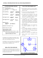
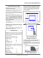
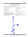
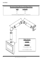
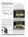
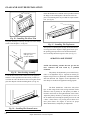
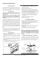
5) The Alpine TR36 fireplace can be installed into
many different applications. See Figure 1 for
examples.
Minimum Gas Line Pipe Size: 1/2”
Electrical: 120 V.A.C. System
Amperage Rating: .62 Amps
Optional Fan Kit : #431-917
Venting: Simpson Duravent Direct Vent (4” x 6 5/8”)
Must use high wind termination on vertical
applications (Simpson part # 0991)
6) Lay out fireplace dimensions on installation site
before proceeding with installation. This will ensure
proper clearances and assist in identifying potential
problems before installation.
7) Make sure to review the vent termination and
positive pressure system requirements before
proceeding.
This appliance may be installed in an aftermarket, permanently located, manufactured home (USA only) or mobile
home, where not prohibited by local codes.
This appliance is only for use with the type of gas indicated
on the rating plate. This appliance is not convertible with
other gases, unless a certified kit is used.
DERATING THE BURNER
The fireplace has been designed to operate at elevations up
to 4500 ft. above sea level. The fireplace will need to be
derated at elevations above 6500 ft. The orifice will need to
be reduced one number drill size.
4
Fig. 1 – Installation Placement Options
Alpine TR36 Direct Vent Gas Fireplace
INSTALLATION REQUIREMENTS
GAS LINE INSTALLATION
IMPORTANT: Gas piping should be installed only by
trained and qualified technicians.
The appliance and its individual shut-off valve must be
disconnected from the gas supply piping system during any
pressure testing of that system in excess of 1/2” psi.
The appliance must be isolated from the gas supply piping
system by closing its individual shutoff valve during any
pressure testing of the gas supply piping system at test pressures
equal to or less than 1/2” psi.
The gas line can be brought through the left side of the
appliance. The 1/2” service gas line must connect to the
flexible appliance connector which is attached to the main
control valve. DO NOT MAKE THIS CONNECTION
UNTIL ALL PRESSURE TESTING OF THE GAS
PIPING SYSTEM IS COMPLETE. FAILURE TO
DO SO WILL RESULT IN DAMAGE TO THE
MAIN CONTROL VALVE.
Gas piping must conform to the current National Fuel Gas
Code, ANSI Z223.1.
Always consult with the local code official for additional local
codes applicable in your area.
IMPORTANT: Always check for gas leaks with a soap
and water solution or gas leak detector. Never use open
flame for leak testing.
NOTE: If the appliance is to be installed on carpeting,
vinyl tiling, or any other combustible material other
than wood flooring, the appliance must be installed on
a metal or wood panel extending the full width and
depth of the appliance.
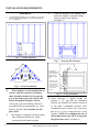
6 "m in
Fig. 2 – Clearance to an adjacent wall
12
10
14
8
6
4
CLEARANCES
8
6
4
2
0
IMPORTANT: Clearances listed in this manual must
be adhered to strictly. Failure to maintain these listed
clearances of the fireplace and venting system can result in a house fire.
Clearance to Combustibles from:
Fireplace Spacers
0”
Fireplace Floor
0”
Ceiling
18”
Ceiling (Flex Vent)
24”
Side Mantel Leg
6”
Mantel Clearance:6” minimum height for a 6”
projection. Add 1” of height for each additional
1” of projection.
Horizontal Vent Pipe
Top of Pipe
Sides of Pipe
Bottom of Pipe
Vertical Vent Pipe
2”
1”
1/2”
1 1/2”
0
1 2 " M a n te l
S h e e tr o c k
12
10
NOTE: To properly check gas pressure, both inlet and
manifold pressures should be checked using the valve
pressure ports on the control valve.
2
6"
M a n te l
12 "
6"
Top of
F ir e p la c e
S id e V ie w o f
F ir e p la c e
Fig. 3 – Mantel Clearances
HEARTH MATERIALS
A Hearth is not mandatory with the TR 36 fireplace, but
is recommended for aesthetics and for added safety .
Non-combustible materials such as Tile, Brick, Rock, and
Slate are recommended.
In constructing a hearth, hearth material thickness must
be taken into consideration. Avoid using any material that
will block the front of the valve access door at the bottom
of the appliance.
Fig. 4 – Hearth Clearances
Alpine TR36 Direct Vent Gas Fireplace
5
INSTALLATION REQUIREMENTS
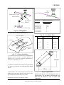
FRAMING
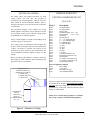
1)
4)
A rough framed opening of 37 1/2” wide by 33 1/2” high
will be required for installation. The minimum depth is
21”. ( see figure 5 )
Center the fireplace in the framing and
anchor the fireplace, using the nailing
strips provided, to the framing.
(see figure 7)
33-1 2 "
height
NAILING TABS MUST BE BENT
OUT BEFORE FIREPLACE IS
INSERTED INTO FRAMING
THERE ARE FOUR NAILING TABS
37-1 2 "
w idth
Fig. 5 – Framed Opening
Fig. 7 – Securing The Fireplace
45"
tile or other non
combustible facing may
be placed against the
fireplace or even
overlap the fireplace
face.
64"
Fig. 6– Corner Installation
2)
If the fireplace is to be installed into an
exterior wall, the enclosure or fireplace
chase should be insulated to the same degree as the home to prevent cold air infiltration through the fireplace chassis.
Check with your local building official for
any additional local requirements ( e.g. vapor
barriers, drywall). Never insulate the fireplace itself.
3)
The fireplace is equipped with four nailing
tabs, which must be bent out before
inserting into the framed opening.
6
sheetrock and other
combustibles may be
brought to within 1/2"
of the fireplace face
but may not overlap or
even contact the
fireplace.
Fig. 8 – Facing Clearances
5) When sheetrock is applied around the
fireplace a 1/2” gap must be maintained
between the fireplace face and the sheetrock
or any other combustible material. Noncombustibles such as brick, tile or stone may
butt up to or even overlap the face of the
fireplace. NOTE: If overlapping the face of
the fireplace make sure not to overlap into
the glass frame area. (see figure 8)
Alpine TR36 Direct Vent Gas Fireplace
VENTING
VENTING PLANNING
SIMPSON DURAVENT
The Alpine TR-36 uses Simpson Duravent Co Axial
venting systems. The inner tube vents products of
combustion away from the appliance, while the outer tube
draws outside air into the combustion chamber. This is a
closed system and uses no air from the interior of the home
for combustion.
VENTING COMPONENTS LIST
Never attach this fireplace vent to another vent serving
another appliance. Each direct vent gas appliance must use
its own separate venting system. Common venting systems
are prohibited for use with this appliance.
Always vent the fireplace to outside of the building. Never
vent into a garage or enclosed area.
This venting system, in combination with the Alpine TR36 Direct Vent Gas Fireplace, has been tested and listed as
a direct vent heater by Intertek. The location of the
termination cap must conform to the requirement in the
Vent Termination Clearances diagram on page 8 of this
manual.
Before proceeding with installation, carefully examine the
chart on page 8 of this manual for options regarding proper
placement of the vent termination.
(4”x6 5/8”)
Stock #
Description
09384
09383
09310
09311
09312
09325
09183
09381
09382
09341
09033
09372
09373
09374
09422
09422
09317
09375
09380
09388
09387
09376
45 Degree Elbow
90 Degree Elbow
Storm Collar
Standard Flashing 0/12 – 5/12
Steep Flashing
6/12 – 12/12
Wall Strap
Firestop Spacer
11” - 14” Adjustable pipe
17” - 24” Adjustable pipe
6” Adjustable pipe
9” Adjustable pipe
12” pipe
24” pipe
36” pipe
48” pipe
6 5/8 pipe
Vertical Termination Cap
Horizontal Termination Cap
Wall Thimble
14” Snorkel Termination Cap
36” Snorkel Termination Cap
Vinyl Siding stand-off
Parts not supplied by Simpson
09362
Flue Adapter
09364
Vent Guard
09367
Horizontal Firestop
09301
Attic Insulation Shield
CLEARANCE TO
COMBUSTIBLES ON
HORIZONTAL PIPE IS
2" FROM TOP
1 " FROM SIDES
1/2" BOTTOM
In all cases, adequate combustion and ventilation air must
be available for the fireplace. Never block the termination cap. Make sure foliage does not grow around the
termination cap. In all cases, follow the clearances listed
on page 8 of this manual.
CLEARANCE
FROM
VERTICAL
PIPE TO
COMBUSTIBLES
IS 1-1/2"
NOTE: Never connect this gas appliance to a chimney
flue serving a separate solid-fuel burning appliance.
Figure 9 – Clearance to Venting
Alpine TR36 Direct Vent Gas Fireplace
7
8
V
P
E
V
M
24"
V Vent terminal
B
F
Alpine TR36 Direct Vent Gas Fireplace
H= Not to be installed above a meter / regulator assembly within (3’)
G= Clearance to inside corner (12”)
F= Clearance to outside corner (19”)
E= Clearance to unventilated soffit (min. 15”)
D= Vertical clearance to ventilated soffit located above the terminal
within a horizontal distance of (24”) from the centerline of the
terminal (min. 18”)
(recommended to prevent condensation on window)
C= Clearance to permanently closed window (12”)
B= Clearance to window or door that may be opened (12”)
V
B
B
V
Openable
V
A
K
B
A
24"
Vertical
Termination
H
J
N
Area where terminal is not permitted
B
V
18"
V
L
A
Matthew Hobby is the coolest!
- Only permitted if veranda, porch, deck, or balcony is
fully open on a minimum of two sides beneath the floor.
- A vent shall not terminate directly above a sidewalk
or paved driveway which is located between two single
family dwellings and serves both dwellings.
Note:
P= Clearance to obstructions in front of the termination such as bushes,
fences, sheds, decks, other structures is (24”)
N= Clearance under a veranda, porch, deck, or balcony (min. 12”)
M= Clearance above paved sidewalk or a paved driveway located on
public property (min. 84”)
A Air supply outlet
Openable
V
B
Fixed
Closed
C
V
V
A
G
Inside
corner detail
A= Clearance above grade, veranda, porch, deck, or balcony (min. 12”)
D
Vertical
Termination
VENTING
VENT TERMINATION CLEARANCES
VENTING
SIMPSON DURAVENT VENTING
Horizontal or Vertical Terminations
The Simpson Dura Vent System offers a complete line of component parts for both horizontal and vertical installations.
Read installation instructions included within the termination cap box.
The following is a list of components required for a basic
horizontal termination installation.
The following is a list of components required for a basic
vertical termination installation.
1 Horizontal Termination Cap
1 90 Degree Elbow
1 Flue Adapter (installed on unit from factory)
1 Horizontal Firestop
1 12” Pipe
1 17” -24” Adjustable Pipe
If vinyl or is to be used, a vinyl siding standoff should
also be used. If brick or rock is to be applied to the
exterior of the home, make sure that the cap is extended
to the thickness of the brick or rock. The Terminal must
never be recessed into the wall. A brick standoff is
available for this application.
1
1
1
2
1
Vertical Termination Cap
Storm Collar
Roof Flashing *
36” vent pipe
Flue Adapter (installed on unit from factory)
* If the home has a chase projecting above the roof line, a
roof flashing will not be needed.
The vertical termination should project above the finished
chase a minimum of 10”. See local codes for other venting requirements in your area.
Alpine TR36 Direct Vent Gas Fireplace
9
VENTING
Vertical Venting
Maximum Vertical Height 37 FT.
Minimum Vertical Height 4 FT.
Up to eight (8) 45 Degree elbows may be used
NOTE: A vent restrictor must be installed in the
fireplace if the vertical height is more than 12 feet.
Only Simpson Duravent GS Piping (4” x 6 5/8”)
May be Used on This Appliance.
Piping Clearances
Vertical Pipe
1 1/2” to Combustibles
Horizontal Pipe
2” To Combustibles—Top
1” To Combustibles—Sides
1/2” To Combustibles—Bottom
10
Alpine TR36 Direct Vent Gas Fireplace
VENTING
Piping Clearances
Vertical Pipe
1 1/2” to Combustibles
Horizontal Pipe
2” To Combustibles—Top
1” To Combustibles—Sides
1/2” To Combustibles—Bottom
Venting With Four (4) 90 Degree Elbows
V (min)
H (max)
V1 (min)
H1 (max)
V2 (min)
1 FT
3 FT
5 FT
3 FT
3 FT
2 FT
5 FT
5 FT
5 FT
3 FT
3 FT
10 FT
5 FT
10 FT
3 FT
NOTE: Horizontal Piping Must Maintain a 1/4” Rise Per Foot.
Alpine TR36 Direct Vent Gas Fireplace
11
12
Alpine TR36 Direct Vent Gas Fireplace
1/2” To Combustibles—Bottom
1” To Combustibles—Sides
2” To Combustibles—Top
Horizontal Pipe
1 1/2” to Combustibles
Vertical Pipe
Piping Clearances
16 FT
8 FT
3 FT
Horizontal
NOTE: Horizontal piping must maintain a 1/4” rise per foot .
3 FT
2 FT
1 FT
Vertical
Horizontal Venting With One 90 Degree Elbow
VENTING
VENTING
Horizontal Venting With Three (3) 90 Degree
Elbows
V (min)
H (max)
H + H1 (max)
1 FT
3 FT
6 FT
2 FT
4 FT
8 FT
3 FT
6 FT
12 FT
4 FT
8 FT
16 FT
5 FT
16 FT
16 FT
NOTE: Horizontal Piping Must Maintain A 1/4” Rise Per
Foot.
Note: V1 must be at least a 1 foot length.
Piping Clearances
Vertical Pipe
1 1/2” to Combustibles
Horizontal Pipe
2” To Combustibles—Top
1” To Combustibles—Sides
1/2” To Combustibles—Bottom
Alpine TR36 Direct Vent Gas Fireplace
13
VENTING
Horizontal Venting With Two (2) 90 Degree Elbows
V (min)
H + H1 (max)
3 FT
8 FT
4 FT
10 FT
5 FT
12 FT
NOTE: Horizontal Piping Must Maintain A 1/4” Rise Per Foot.
Piping Clearances
Vertical Pipe
1 1/2” to Combustibles
Horizontal Pipe
2” To Combustibles—Top
1” To Combustibles—Sides
1/2” To Combustibles—Bottom
14
Alpine TR36 Direct Vent Gas Fireplace
VENTING
VENTING – HORIZONTAL
Install the vent system according to the instructions
included in the venting kit received with the fireplace.
1. With the unit in the desired location, check to determine
if wall studs or roof rafters will obstruct the venting system
when attached. If this is the case, you may want to adjust
the location of the unit or consult with your framing
contractor for options in adjusting the framing.
2. Determine where the horizontal vent pipe will exit
through the exterior wall. Frame a 10” x 10” opening at the
exit location and mount the horizontal firestop. This
firestop will assure that all clearances to the vent pipe are
maintained . (See fig. 10)
Mill-pac
Sealant
Silicone Sealant
Fig. 11 – Applying Sealant
NOTE: Clearances to combustibles from the vent pipe
must be adhered to. See the table below for proper
clearances.
Horizontal Venting Clearances
Fig. 10 – Horizontal Firestop
3. To properly assemble the Simpson Vent pipe a high
heat sealant , such as Mil-Pac or Dap High Heat Mortar,
should be used to ensure an airtight vent. Apply the sealant
to the inner collar of the pipe, line up the lugs on the outside of the pipe, slip the pipe together and then twist the
pipe to lock the lugs together (see fig 11). Wrap the outer
seam of the vent pipe with aluminum tape or seal with silicon.
NOTE: All pipe joints must be sealed with Mill-pac or
Dap High Heat Mortar on the inner pipe and aluminum
tape or Silicone on the outer joint.
TOP OF PIPE
2” to combustibles
SIDES OF PIPE
1” to combustibles
BOTTOM OF PIPE
1/2” to combustibles
4. Install the vertical pipe needed, followed by the elbow to
achieve the pre-determined exit height and than extend the
horizontal section of vent through the pre-mounted
horizontal firestop. The pipe extending through the
exterior wall should not extend beyond the surface, which
the termination cap will be mounted to, more than 1” but
needs to be at least flush with this surface ( see fig. 12).
5. Carefully slide the vent termination over the vent pipe
from the outside and flush it up against the exterior wall.
Level the termination cap for appearance sake, making sure
the arrow is pointing upward on the termination cap (see
fig. 13). Carefully fasten the termination cap to the exterior
wall (see fig. 14) using the screws provided in the
termination box. You may seal around the termination cap
with a quality silicone for insulation purposes.
Alpine TR36 Direct Vent Gas Fireplace
15
VENTING
VERTICAL TERMINATION
1.
Maintain the 1-1/2” clearances to combustibles
when passing through ceilings, walls, roofs, enclosures,
attic rafters, or other nearby combustible surfaces. See the
diagrams on page 11 of this manual for the maximum
vertical rise of the venting and the maximum horizontal
offset limitations.
Fig. 12– Pipe Through Wall
2.
With the gas appliance in its desired location,
drop a plumb bob from the ceiling to the position of the
appliance flue exit and mark the location where the vent
will penetrate the ceiling. Drill a small hole at this point.
Next, drop a plumb bob from the roof to the hole
previously drilled in the ceiling and mark the spot where
the vent will penetrate the roof. Determine if ceiling joists,
roof rafters, or other framing will obstruct the venting
system. You may choose to relocate the fireplace or offset
the venting to avoid cutting framing members (see figure
16).
Make Sure Arrow
is pointing up.
Wall Penetration
Heat Shield
F la s h in g
HOT
F ire s to p
Fig. 13– Termination Orientation
Fig. 15– Vertical Venting
3. A Firestop spacer must be installed in the floor or ceiling
of every level. To install the Firestop spacer in a flat ceiling
or wall, cut a 10 inch square hole. Frame the hole as
shown in (Figure 17) and install the firestop.
FIRESTOP
4. Assemble the desired lengths of pipe and elbows. Ensure
that all pipes and elbow connections are in the fully twist–
locked position and sealed with Stove Mate brand sealant
on the inside collar and aluminum tape on the exterior. An
air tight must be created.
Fig.14– Anchoring Termination to Wall
16
Alpine TR36 Direct Vent Gas Fireplace
VENTING
Vent Height
P lu m b e r s T a p e
W a ll S tr a p
4 5 d e g re e
E lb o w
Roof Pitch
F ir e s to p
Flat to 9/12
9/12 to 10/12
10/12 to 11/12
11/12 to 12/12
12/12 to 14/12
14/12 to 16/12
16/12 to 18/12
Fig. 16– Venting Offsets
Minimum Vent Height
Above Roof Line
2’
2-1/2’
3-1/4’
4’
5’
6’
7’
See Offset Table for additional details (fig. 19).
Fig. 18 – Vent Height Table
10" x 10" Square
Hole
Offset
Pipe Length (L)
Height
Framing
Firestop
Spacer
Fig. 17 – Firestop Installation
5. Cut a hole in the roof centered on the small drilled hole
placed in the roof in Step 2. The hole should be of
sufficient size to meet the minimum requirements for
clearance to combustibles of 1 1/2”.
4-3/4”
0”
13-1/4”
9”
6”
17-1/2”
11-1/4”
9”
19-1/2”
L
H eight
6. Continue to complete the assembly of the pipe lengths.
See (figure 18) for proper vent height projecting through
the roof.
7. Ensure that the vent is vertical and secure the base of the
flashing with roofing nails. Slide the storm collar over the
pipe section and seal with a mastic type sealant.
8. Install the vent cap by twist locking it in place.
O ffset
Fig.19 – Offset Table
NOTE: If the pipe is to pass through any closets or
storage spaces, the vent must be enclosed. The vent
must never be allowed to come in contact with
combustibles
Alpine TR36 Direct Vent Gas Fireplace
17
FLEX VENTING
INSTALLING FLEX VENT
Flex vent may be used in a number of basic installations to simplify the
installation process. It must be noted that the use of flex vent increases
the height of the ceiling (as shown in the illustration below right) by
6”. It also needs to be noted that all firestopping practices must be
adhered to with flex venting also.
There are spacers Provided to maintain the orientation between the
two liners. The spacers need to be utilized at the beginning and the
end of a 90° transition and also at 12” intervals during the horizontal
run of the flex vent. ( see below)
It is recommended that a high temperature sealant such as Mill Pac or Dap
High Heat Mortar be used to seal the center flex liner to the appliance vent
nipple as well as the vent nipple on the termination cap. Aluminum tape
or silicone is recommended to seal the outer flex liner to the appliance and
to the vent termination. All four points of connection should be fastened
with a band clamp.
As noted in the venting chart below, there must be a minimum of 1’ of
vertical rise before the transition into the horizontal . 1’ of vertical rise
will provide a maximum of 2’ horizontal run, which will accomplish
most exterior wall applications. 2’ of vertical rise will accommodate up to
3’ of horizontal run, which is the maximum horizontal run allowable with
flex vent. Only one 90° transition may be used with the flex vent taking it
from the vertical to the horizontal. Offsetting in the horizontal plane is not
allowed.
The maximum horizontal run may be 3’ with a minimum vertical rise of
3’ as shown in the chart below. A maximum vertical run of 8’ may be
utilized. If your vertical run is greater than 3’ you may incorporate up to
two bends into the vertical run. The bends must not exceed 45°.
Piping Clearances
Vertical Pipe
1 1/2” to Combustibles
Horizontal Pipe
2” To Combustibles—Top
1” To Combustibles—Sides
Horizontal Venting With One 90 Degree Elbow
Vertical
Horizontal
1 FT
2 FT
2 FT
3 FT
3-8 FT
3 FT
2"
NOTE: Horizontal piping must maintain 1/4” rise per foot.
24"
12"
INCORRECT
18
CORRECT
Alpine TR36 Direct Vent Gas Fireplace
WIRING
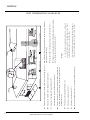
WIRING THE FIREPLACE
NOTE: Electrical wiring must be installed by a licensed
electrician.
NOTE; The appliance must be electrically grounded in
accordance with the local codes, or in the absence of
local codes with the current National Electrical Code,
ANSI/NFPA 70.
OPTIONAL BLOWER
The fireplace needs to have a 110-120 VAC power supply,
preferably on a switch, wired to the factory installed junction box before the fireplace is permanently installed. The
optional blower requires this power source to operate.
Use blower kit 430-917
High Temperature Wire
With Fiberglass Shield
Secured to Floor
Ground
Black
Black
White
Appliance Cord
w/Fiberglass Shield
Secured to Floor
2 Conductor
Plug &Recepticle
120 v. Power Source
(Switched)
NOTE: Proper grounding must be maintained on the
appliance and on the blower assembly.
The appliance is also equipped with a millivolt system that
NOTE: Do not allow any wiring to rest against the
appliance as fire danger may result.
strand wire set needs to be routed from the main gas
NOTE: DO NOT connect any electricity to the main
gas control valve wiring. Valve damage will certainly
occur.
NOTE: Electrical wiring must be installed by a
licensed electrician.
controls the main gas control valve. A low voltage two
control valve to the desired position of the wall switch.
Some prefer the switch be co-located with the power
switch for the optional blower.. If this choice is made, a
DIVIDED double gang electrical box must be installed. (A
standard (non-divided) double gang box cannot be used.)
Alpine TR36 Direct Vent Gas Fireplace
19
WIRING/LOG INSTALLATION
When installing the low voltage wiring. It is essential that
the wires be marked so as to never have 110 volt /24 volt
power attached to them. If power is attached to the control
valve, damage will certainly occur.
The appliance generates the millivoltage needed to operate
the gas control system. A standard wall toggle switch or a
millivolt thermostat may be used to control the main gas
valve.
LOG INSTALLATION
Carefully remove logs from their packaging . You will
notice that your Alpine Gas Fireplace logs are extremely
lightweight and are very fragile, care must be taken when
handling. It is also important to note that the positioning of
the logs in the fireplace is very critical , the logs must be
installed as instructed in this manual to maintain an attractive and clean burn. NOTE: DO NOT CHANGE THE
LOGS ORDER OF INSTALLATION IN ANY WAY.
The millivolt system has limitations on the distance it can
be installed from the fireplace. The greater the distance
from the fireplace, the larger the wire size must be to
prevent loss of the millivoltage. See the table below for
recommendations.
Wire Guage
Maximum Length
9’
22 ga.
13’
20 ga.
20’
18 ga.
30’
16 ga.
50’
14 ga.
Fig. 21 – Back Log
Millivolt thermostats and remote controlled millivolt
thermostats are available from your Alpine dealer.
Locate the back log (36-1) and position it over the locating
pins on the back of the burner. ( fig.21)
See (figure 20) for wiring illustration of the control valve.
A snug connection must be made at the control valve and
the switch location to ensure reliable operation. Do not
over tighten the screws at the control valve, they will strip.
Note: Local codes need to be followed when installing
any electrical appliance. If conflicts between this
manual and local electrical codes exist. Local codes
always prevail.
To thermopile
TP TH
TP
HI
LO
To wall switch,
remote control
or thermostat
TH
PILOT
Fig. 20 – Millivolt System
20
Fig. 22 – Side Logs
Locate the left side log (36-2) and place it so the flat side
faces the left side wall. Push it back against the back log
and swing the front towards the center of the firebox until
the log hits the grate. Locate the right side log (36-3) and
position it so the flat side faces the right side wall. Push it
back against the back log and swing the front towards the
center of the firebox until the log hits the grate. ( fig.22)
Alpine TR36 Direct Vent Gas Fireplace
LOG INSTALLATION
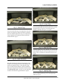
Fig. 25 – Center Twig
Fig. 23– Bottom Twigs
Locate the center twig (36-7) and place its single end into
the receiving hole/pad on the back log and rest its Y end on
the bottom twigs (36-4 & 36-5). The center grate iron
should be centered in the logs Y. ( see fig.25)
Locate the bottom left twig (36-4) and position it onto the
left pair of locating pins with the burned face towards the
front. Next find the right bottom twig (36-5) and position it
onto the right pair of locating pins with the burned face
towards the front. (fig.23)
Fig. 26 – Right Top Twig
Locate the right top twig (36-6) and place its Y into the pad
on the right side log (36-3) and let its single end rest on the
burner . There is a dead spot on the burner for the log. (see
fig.26)
Fig. 24 – Ember Placement
The ember placement is critical for the appearance of the
fireplace as it is burning but can also cause improper combustion if not applied correctly. Take small dime sized
pieces of ember material and place it directly behind the
burner ports along the front of the burner. NOTE: DO NOT
COVER BURNER PORTS. You may cover the dead areas
on either side to hide the log pads and burner. (fig.24)
Fig. 27 – Left Top Twig
Locate the top left twig (36-8) and place it on the left side
log (36-2) and left bottom twig (36-4) onto the pads provided. (see fig. 27)
Alpine TR36 Direct Vent Gas Fireplace
21
GLASS AND LOUVER INSTALLATION
Fasten the bottom louver with the screws provided. Anchor
the hinges to the mounting tabs at the bottom of the fireplace. The mounting holes are provided for simple installation. (see fig.30)
Fig. 28 – Installing The Glass Trim
The glass trim hangs on the top rail and rests on the sealing
surface of the fireplace. ( see fig. 28)
Pull hook forward
and up to slot
on door bracket
Fig. 31 – Installing The Top Louver
The top louver is held in place by drop in tabs that fit into
receiving slots on the fireplace. Simply place louver up to
the opening, push up on the louver and back and let the
louver tabs drop into their respective slots. (see fig. 31)
AERATION ADJUSTMENT
NOTE: The following assumes that the gas line has
been connected and leak tested by a qualified
technician.
Fig. 29 – Door Locking Assembly
Locate the door hooks in the control area of the appliance
and one at a time pull the hook out towards you until you
can insert the end of the hook into the receiving hole on the
glass trim. Repeat with the remaining hook. (see fig. 29)
The primary air adjustment is preset at the factory.
Little or no adjustment may be required for natural gas.
Propane will perform very differently at different altitudes
and from different fuel suppliers. Some adjustment will
most likely be needed for an appliance burning propane.
The flame should have a blue base with yellow
tips. A dark orange flame with sooting and black smoke
indicates a lack of primary air. The primary air shutter is
located in the firebox on the right hand side of the burner.
Adjust the primary mixture by loosening the set screw on
the air shutter and increasing the opening for more air and
a bluer / cleaner flame, or by closing the air shutter for a
more yellow flame. See (figures 32 and 33) for proper
flame characteristics, and primary air adjustment.
Fig. 30 – Installing The Bottom Louver
22
Alpine TR36 Direct Vent Gas Fireplace
AERATION ADJUSTMENT/REMOTE CONTROL & THERMOSTAT
REMOTE CONTROL (Optional)
An Alpine Remote Control Kit (08501) may be installed on
this fireplace. The remote control kit comes with a hand
held transmitter, a receiver, a wall mounting plate, and a
wall mounted transmitter cradle. The remote control is
thermostatically controlled so you can set the fireplace to
the desired room temperature, and have that temperature
maintained. The remote control is battery powered and will
require periodic maintenance to keep the system working
properly.
Venturi
Venturi Set Screw
1. Choose a convenient location on the wall to install the
receiver unit. A standard electrical box may be used. Run
wires from the fireplace valve to the desired wall location.
See the millivolt lead table on page 14 of this manual for
maximum wire runs.
2. Connect the wires to the gas valve (see figure 34).
Fig. 32 – Primary Air Adjustment
3. Follow the installation instructions included with the
remote control kit.
To thermopile
PILOT
TH
HI
YELLOW TIPS
BLUE FLAME
TP TH
TP
LO
To wall switch,
remote control
or thermostat
Fig. 34 – Gas Valve Connection
BURNER BASE
Fig. 33 – Proper Flame Characteristics
WALL THERMOSTAT (Optional)
A wall thermostat may be installed if desired. Follow the
wire routing instructions on page 14 of this manual. Alpine
offers two types of wall mounted thermostats. One is a
basic heating type thermostat (part # 08260). The other is a
programmable model (part # 08261). See your Alpine
dealer for additional information on the thermostats.
NOTE: If a Wall Thermostat is desired, there is no
need to install a wall junction box. The thermostat wire
will simply need to be routed to the desired location of
the wall thermostat and made accessible through a
small hole in the drywall. Both types of thermostats are
surface mounted on the finished wall. They should not
be installed until painting is complete.
Alpine TR36 Direct Vent Gas Fireplace
23
OPERATING INSTRUCTIONS
FOR YOUR SAFETY READ BEFORE LIGHTING
This appliance must be installed in accordance with local codes, if any;
If not, follow the current ANSI Z223.1
WARNING: If you do not follow these instructions exactly, a fire or
explosion may result causing property damage, personal injury or loss of
life. Improper installation, adjustment, alteration, service or maintenance
can cause injury or property damage. Refer to the owner’s information
manual provided with this appliance. For assistance or additional
information consult a qualified installer, service agency or gas supplier.
A) This appliance has a pilot which must
be lighted by hand. When lighting the
pilot, follow these instructions exactly.
B) BEFORE LIGHTING smell all around
the appliance area for gas. Be sure to
smell next to the floor because some
gas is heavier than air and will settle
on the floor.
WHAT TO DO IF YOU SMELL GAS
−
Do not try to light any appliance
−
Do not touch any electrical switch, do
not use any phone in your building.
−
Immediately call your gas supplier from
a neighbors phone. Follow the gas
suppliers instructions.
−
If you cannot reach your gas supplier,
call the fire department.
C) Use only your hand to push in or
turn the gas control knob. Never use
tools. If the knob will not push in or
turn hand, don’t try to repair it, call
a qualified service technician. Force
or attempted repair may result in a
fire or explosion.
D) Do not use this appliance if any part
has been under water. Immediately
call a qualified service technician to
inspect the appliance and to replace
any part of the control system and
any gas control which has been
under water.
This appliance needs fresh air for safe
operation and must be installed so there are
provisions for adequate combustion and
ventilation air.
CAUTION: Hot while in operation. Do not touch. Keep children, clothing,
furniture, gasoline and other liquids having flammable vapors away. Keep
burner and control compartment clean. See installation and operating
instructions accompanying appliance.
LIGHTING INSTRUCTIONS
STOP! Read the safety information above on
this label.
1) Push in gas control knob slightly and turn
clockwise to “OFF”. Knob cannot be
turned from “PILOT” to “OFF” unless
knob is pushed in slightly. Do not force.
2) Wait five (5) minutes to clear out any gas.
If you then smell gas STOP! Follow “B”
in the safety information above on this
label. If you don’t smell gas, go to the next
step.
3) Turn knob on the gas control
counterclockwise to “PILOT”.
Pilot Burner
Clockwise to “OFF”
THERMOPILE
4) Push in control knob all the way and hold
in. Continually push and release the red
button on the spark ignitor until pilot
lights. Continue to hold the control knob
in for about 1/2 minute after the pilot is
lit. Release knob and it will pop back up.
Pilot should remain lit. If it goes out,
repeat steps 1 to 4. If knob does not pop
up when released, stop and immediately
call your service technician or gas supplier. If the pilot will not stay lit after
several tries, turn the gas control knob to
“OFF” and call your service technician or
gas supplier.
5) Turn gas control knob counterclockwise
to “ON”
6) Use the toggle switch to operate main
burner.
TO TURN OFF GAS APPLIANCE
1) Push in the gas control knob slightly and
turn clockwise to “OFF”. Do not force.
2) Turn off all electric power to the appliance
if service is to be performed.
DO NOT REMOVE THIS INSTRUCTION PLATE
24
Alpine TR36 Direct Vent Gas Fireplace
LX-999-1
OPERATING INSTRUCTIONS
OPERATING INSTRUCTIONS
SHUTDOWN PROCEDURE
1) The first fire in your fireplace will help cure the painted
surfaces. To ensure that the paint is properly cured, it is
recommended that you burn your fireplace for at least
four (4) hours the first time you use it with the fan on.
When first operated, the unit will release an odor caused
by the curing of the paint and other components. Smoke
detectors may go off during this initial break-in period.
Open windows or doors in the area of the fireplace to
allow for ventilation during the break-in period.
1) Use the wall switch, thermostat or remote control to turn
off the main burner.
NOTE: When the fireplace is cold and the appliance is
first lit, it may cause condensation and fog the glass. This
condensation is normal and will disappear in a few minutes as the glass heats up.
2) Read and understand these instructions completely before attempting to operate this appliance.
2) The burner and valve control compartments must be
cleaned annually. A vacuum with a brush attachment
works well. The logs should be cleaned gently with a
soft bristle brush. The logs are fragile and are easily
damaged.
3) Be sure that all items in this installation portion of this
manual have been properly completed in compliance to
local codes and this manual.
2) Turn the main gas control clockwise to the “OFF”
position
FIREPLACE MAINTENANCE
1) Before performing any service on the appliance, ensure
the gas has been completely shut off, the unit cooled,
and the electricity shut off to the appliance.
3) Clean the appliance with a damp cloth. Never use
abrasive cleaners. The glass should be cleaned with a
gas fireplace glass cleaner. The glass will slowly build a
thin white film on the inside. This film is normal and
can be removed using a fireplace glass cleaner available
at your local dealer.
4) The fireplace is finished with a high temperature paint.
If your fireplace needs to be repainted or touched up, see
your local dealer for Stove Bright Paint.
LIGHTING PROCEDURE
1) Turn burner OFF using the “ON/OFF” switch or by
turning the thermostat or remote control to the “OFF”
position.
2) Turn gas control knob so indicator points to “OFF”
position and allow 5 minutes for any gas in the
combustion chamber to escape.
3) Turn the gas control knob counterclockwise so the
indicator points to the “PILOT” position. Depress the
gas control knob fully. Depress the igniter button several
times until the pilot lights. After approximately one
minute, release the gas control knob. The pilot flame
should continue to burn. If the pilot does not remain lit,
repeat operation allowing a longer period before
releasing gas control knob.
4) When the pilot stays lit, turn the gas knob further
counterclockwise to the “ON” position.
5) Use the wall switch, thermostat or remote control to turn
on the unit.
6) Rotate the flame height regulator to adjust the flame
height higher or lower.
on
pilot
HI
off
E
LO
A
5) The appliance and the venting system must be inspected
before use, and at least annually, by a qualified field
technician. The vent must be inspected to ensure that the
flow of combustion air and ventilation air is not
obstructed.
6) Do not use this appliance if any part has been under
water. Immediately call a qualified service technician to
inspect the appliance and to replace any part of the
control system and any gas control which may have
been under water.
7) If the venting system is disassembled for any reason it
must be properly resealed as per the instructions in the
venting section of this manual. Never operate the
appliance if the venting system is not properly sealed.
8) The blower system requires annual lubrication. The
blower is marked with lubrication points. Use a good
quality light machine oil for lubrication. Apply three
drops per port annually.
GOLD PLATED or STAINLESS TRIMS
The gold plate or stainless trims on the fireplace require
little maintenance. If the pieces get fingerprints or dust
build-up, you should use a damp cloth only for cleaning.
DO NOT use cleaners of any type on the stainless or gold.
Be sure to clean any fingerprints off of the unit BEFORE
turning the fireplace on.
Alpine TR36 Direct Vent Gas Fireplace
25
SERVICE INFORMATION
GLASS GASKET
THERMOPILE / THERMOCOUPLE
If the glass gasket needs to be replaced, contact your local
dealer for the correct replacement part. Never attempt to
use any gasket, other than the correct replacement gasket
on the glass. Use part # 07840.
1) Remove the glass door
2) Open the bottom valve chamber
3) Double check to make sure gas supply is turned off
4) Disconnect the thermocouple by loosening nut from the
valve with a 9mm wrench. Disconnect the thermopile by
loosening 2 screws marked TP on the valve.
5) Remove the two 1/4” screws holding the pilot assembly
in its bracket. Gently lift the pilot assembly up 2”.
6) Disconnect the thermopile and thermocouple with a
7/16” wrench.
7) Replace the thermocouple or thermopile.
8) Reinstall in reverse order.
GLASS PANEL
WARNING: Do not slam the door or strike the ceramic
panel with a heavy or hard object. Breakage of the
panel will result.
WARNING: Do not operate the appliance with the
glass front removed, cracked, or broken. Replacement
of the glass panel should be done by a qualified service
technician.
Your fireplace is supplied with a 30-1/8”x 19”, high temperature, 5mm ceramic glass panel that is capable of withstanding the highest heat that your fireplace can produce.
Never attempt to use another type of glass or other material. If your glass requires cleaning, you should obtain an
approved gas fireplace glass cleaner available at your fireplace dealer. Do not use abrasive cleaners to clean the glass
panel. DO NOT CLEAN THE GLASS WHEN IT IS
HOT!
In the event that you break your glass by impact, purchase
your replacement from an authorized Alpine dealer. See
the replacement parts list for ordering information. Follow
the replacement steps below.
Replacing the Glass
1) Remove the door by releasing the glass clip springs
found in the valve chamber area.
2) Always where gloves to protect yourself from sharp
edges. Remove all loose or damaged glass from the
frame.
3) Insert the new glass panel with the gasket preinstalled
4) Use the 4 existing Tinnerman glass clips to hold the
glass in place.
5) It is imperative that the glass be spaced in the frame so
that it is lightly resting within the door frame.
LOG REPLACEMENT
The fireplace must never be operated if the logs are broken
or damaged. To replace the logs follow the steps below.
1) Turn off the gas supply and allow the fireplace to cool
completely before servicing.
2) Open the glass door panel.
3) Gently remove the logs from the firebox. Be sure to note
their position.
4) Obtain the proper replacement for the broken log.
5) Replace the log set and close the door panel.
NOTE: It is critical that the logs are placed in the
proper locations. Improper positioning of logs may
create carbon build-up and will severely alter the unit’s
performance. Poor appliance performance caused by
improper log installation is not covered under
warranty.
INSPECTING THE PILOT / BURNER
Periodic inspection of the pilot and main burner is required.
(Figure 43, located on page 24 of this manual), illustrates
proper flame characteristics for the main burner. See
(figure 35) below for proper pilot flame characteristics.
Pilot
Glass with Gasket
Flame should
engulf the top
3/8" to 1/2"
Glass Clip
Thermopile
Quick Drop out
Thermocouple
Fig. 35 – Pilot Flame Characteristics
26
Alpine TR36 Direct Vent Gas Fireplace
SERVICE INFORMATION
REMOVING VALVE
INSTALLING VALVE
1)Open the bottom valve door
1)Mount valve to valve holder
2)Shut off the gas supply
2)Place valve / valve holder back into
position
3)Disconnect the inlet gas line (3/4”
wrench)
3)Secure valve with 2 square nuts
4)Disconnect the 2 TP wires from the
valve
4)Connect main burner gas tube (use
11/16” wrench)
5)Disconnect the 2 TH wires from the
valve
5)Connect the thermocouple to the valve
(use a 9mm wrench)
6)Disconnect the pilot tube from the valve
(use a 7/16” wrench)
6)Connect the pilot tube to the valve (use
7/16” wrench)
7)Disconnect the thermocouple from the
valve (use 9mm wrench)
7)Connect the TH wires to the valve
8)Disconnect the main burner tube
(11/16” wrench)
9)Remove the 2 square nuts securing the
valve holder to the floor
10)Remove the valve from the appliance
CAUTION: Never use an open flame to
check for gas leaks. Always use a soap
solution to check for leaks.
8)Connect the TP wires to the valve
9)Connect the main gas supply to the
valve (use a 3/4” wrench)
10)Double check to make sure all
connection are complete and tight
11)Restore gas supply
12)Using a soap solution, check for leaks
in main gas supply.
13)Make sure the toggle switch is in the
“OFF” Position
14)Ignite pilot and check for leaks in pilot
line
15)Ignite main burner and check for leaks
in main burner tube.
Alpine TR36 Direct Vent Gas Fireplace
27
PARTS LIST
REPLACEMENT PARTS
LIST
07623
Log Set (8 Logs)
08261
Programmable Thermostat
07655
Embers
08260
Thermostat
05149
Glass Clips
430-917
Optional Blower Assembly
07840
Glass Gasket
24504
Glass Trim-Arch
06145
Glass 30-1/8” x 19”
24506
Glass Trim-Standard
04081
Door Spring Hook
24510
Face Top-Arch
09231
Fan Speed Control
08255
White Toggle Switch
04036
S.I.T. Valve Nat. Gas
08991
S.I.T. Regulator L.P.
08221
Thermodisc 180°F
37100
Burner – Nat Gas / Prop
04046
Piezo Igniter
04080
Door Extension Spring
04038
Pilot Assembly –N.G.
05082
Pilot Orifice L.P.
06095
Bottom Door Hinge
08501
Remote Control
24500
Top Door
24502
Bottom Door
28
Alpine TR36 Direct Vent Gas Fireplace
SERVICE INFORMATION
NOTE: Before troubleshooting the gas control system, be sure the external gas shut off is in the “ON” position.
WARNING: TO PREVENT INJURY OR PROPERTY DAMAGE, REMOVE THE GLASS PANEL FROM THE
APPLIANCE BEFORE DOING ANY WORK ON THE GAS CONTROL SYSTEM. FAILURE TO DO SO COULD
RESULT IN GAS BUILD-UP AND EXPLOSION.
GAS SYSTEM TROUBLESHOOTING
PROBLEM
POTENTIALCAUSES
Piezo wire loose
Spark igniter will
not light pilot.
Defective Piezo ignitor
Piezo wire grounding out
Electrode is grounding out
Electrode is sparking at wrong
location
Pilot will not stay
lit after carefully
following lighting
instructions
•
Check for spark at electrode and pilot. If no spark, disconnect
wire at electrode, put wire to ground, and try igniter again. If still no
spark follow the Piezo wire to Piezo igniter to see where grounding
may be occurring. Position electrode into pilot so gas may be able to
contact spark.
•
Defective thermopile
Check pilot flame, must impinge on thermopile and
thermocouple
Defective thermocouple
• Clean and/or adjust pilot so pilot is enveloped around
thermopile and thermocouple.
Thermopile / thermocouple
grounding out.
• Be sure wire connections at gas valve terminals are tight and
thermopile and thermocouple are fully inserted into pilot bracket
Loose thermopile leads
TP-THTP on valve
Defective automatic gas valve
Pilot burning, no gas
to burner.
Valve wire connections are
loose
Valve knob is on
Valve wires are defective
•
•
Check switch wires to make sure they are not grounding
Check thermopile with millivolt meter. Take reading at
thermopile terminals of valve TP-TPTH. Should read 250 millivolts
minimum while thermopile has pilot flame on it.
• With the pilot ignited, turn valve knob to on. Take reading at
TP-TPTH with on/off switch in on position. Reading should be
100mv or greater. If reading is OK and pilot does not hold, replace
•
Check two way switch / wall switch for proper connections.
Jumper wire across terminals at wall switch. If burner comes on,
replace switch.
• If okay, jumper wire at valve (TH-THTP). If unit turns on, replace wires or check for loose connections.
Wall switch is on
Frequent pilot outage problems
CORRECTIVE ACTION
Pilot flame may be too low or
blowing high causing the pilot
safety to drop out
Wall switch wires may be
grounding out.
Thermopile or thermocouple
may be grounding out.
•
Clean and adjust pilot for maximum flame impingement
on thermopile and thermocouple.
•
Trace wires from valve to wall switch for possible damage or grounding against appliance or gas supply. Trace thermopile wires from valve to thermopile for possible grounding
against the appliance or gas valve.
Caution:
Any safety screen or guard removed for servicing an appliance must be replaced prior to
operating the appliance
Alpine TR36 Direct Vent Gas Fireplace
29
WARRANTY
LIMITED LIFETIME WARRANTY
COVERAGE - This Limited Warrranty is issued by Alpine Gas Fireplaces, a division of Alpine Supply Company ("Alpine"), and extends only to the original
consumer purchaser. THIS WARRANTY GIVES YOU SPECIFIC LEGAL RIGHTS, AND YOU MAY ALSO HAVE OTHER RIGHTS WHICH VARY FROM STATE TO
STATE.
LIMITED ONE YEAR WARRANTY
The Alpine Gas Fireplace is warranted to be free of defects in materials and workmanship (does not include installation materials and installation labor) for a
period of one (1) year from the date of purchase when installed and used in accordance with the recommendations in the installation and operation instructions for the fireplace. The determination as to the existence of a defect and whether or not that defect is material shall be made in accordance with accepted
industry standards. Defective parts will be repaired or replaced at Alpine's option. Parts which are returned to Alpine and found defective on inspection will be
repaired, or replaced with a new part, without charge to the purchaser as long as the part is still under warranty. All shipping charges will be paid by the
purchaser, and all new or repaired parts shipped to the purchaser shall be shipped freight collect (F.O.B. Lehi, Utah). Service calls ordered by the customer,
repairs, or parts which do not qualify for warranty shall be charged to the customer at then current rates for labor, parts and transportation.
LIMITED LIFETIME WARRANTY
In addition to the one year warranty described above, the firebox of the Alpine Gas Fireplace is warranted for life against through wall perforation when installed and used in strict compliance with the recommendations in the installation and operation instructions for the fireplace, provided that the blower has
been installed and been kept operable and working whenever the fireplace has been in use, and there has been an approved and tested vent cap in place on
the chimney to prevent moisture from coming down the flue and causing the rusting of the firebox or other components. For purposes of this lifetime warranty, burnout means only the eroding of the interior metal floor, top, walls or heat exchanger in the top of the appliance, solely by fire action, to the point that
the erosion has resulted in one or more holes from inside of the firebox into the surrounding hot air chambers of the appliance. This lifetime warranty does
not cover warping or rusting of the firebox. The damaged part or parts of the firebox will be repaired or replaced at Alpine's option. Parts which are returned
to Alpine and are found damaged by burnout on inspection will be repaired, or replaced with a new part, without charge to the purchaser as long as the unit is
still under warranty. All shipping charges shall be paid by the purchaser, and all new or repaired parts shipped to the customer shall be shipped freight collect (F.O.B. Lehi, Utah). If the damaged part or parts under warranty cannot reasonably be removed and shipped to Alpine for replacement or repair, Alpine
will provide a serviceman to correct the defect at the location where the gas fireplace is installed without charge to the purchaser for labor or materials, provided that the purchaser shall pay a reasonable charge for the transportation of the serviceman and needed parts and equipment from the nearest Alpine
service center to the location of the appliance and return.
LIMITATIONS - These one year and limited lifetime warranties are in lieu of all other express warranties. ALL IMPLIED WARRANTIES, INCLUDING ANY IMPLIED WARRANTIES OF MERCHANTABILITY OR OF FITNESS FOR ANY PARTICULAR PURPOSE, ARE SPECIFICALLY LIMITED TO A TERM OF ONE (1) YEAR
FROM THE DATE OF PURCHASE (SOME STATES DO NOT ALLOW LIMITATIONS ON HOW LONG AN IMPLIED WARRANTY LASTS, SO THE ABOVE LIMITATION MAY NOT APPLY TO YOU). Alpine neither assumes nor authorizes any other person to assume for it, any additional liability in connection with the sale,
installation, replacement, or repair of the appliance.
EXCLUSIONS Alpine shall be held free and harmless from liability damage to property or injury to persons related to the installation or operation, proper or
improper, of the appliance. THESE ONE YEAR AND LIMITED LIFETIME WARRANTIES DO NOT COVER, NOR DOES ALPINE ASSUME, RESPONSIBILITY FOR
INCIDENTAL, SECONDARY, OR CONSEQUENTIAL DAMAGES. ( SOME STATES DO NOT ALLOW THE EXCLUSION OR LIMITATION OF INCIDENTAL OR CONSEQUENTIAL DAMAGES, SO THE ABOVE LIMITATION OR EXCLUSION MAY NOT APPLY TO YOU.)
These one year and limited lifetime warranties do not cover:
1. Damage or malfunction resulting from accident, negligence, abuse, alteration, unauthorized service, damage during transportation, shipping or damage
caused by external fire, floods, acts of God, or any other casualty.
2. Damage or malfunction resulting from failure to follow the installation or operating instructions provided with the fireplace unit.
3. Damages or defects in any parts, equipment, accessories, materials, or items not manufactured, sold, or supplied by Alpine, or any damage resulting from
the use of such items, which are used on or in connection with the fireplace unit.
4. Damage to or defects in any glass windows or internal or external finishes, or any damage resulting there from, except as an examination by the
chaser may reveal at the time of delivery of the appliance and is reported immediately to Alpine.
pur-
5. Any expansion and contraction noises commonly found in heating equipment.
6. Damage or malfunction caused by trees or bushes located in the proximity of the vent or vent termination.
PROCEDURE TO OBTAIN PERFORMANCE UNDER WARRANTY It is recommended that you first contact your local dealer as the dealer may be able to assist
you with warranty or other service work. In any case, the following procedure must be followed for any and all warranty work;
If damage occurs or a defect is discovered which you believe is covered by this limited warranty, you must promptly notify Alpine of the damage or defect in
writing and provide reasonably satisfactory proof of the date of purchase of the appliance. All claims made by you under this warranty should be directed to
Alpine at the address below. The written notice must contain the name, address and phone number of the customer, as well as the name of the dealer, the
serial number of the appliance and the date purchased. Failure to give timely notice to Alpine of any material damage or defect will result in that damage or
defect being excluded from coverage.
Upon receipt Alpine will, within 60 days, repair, replace or service the parts or unit as covered by this Limited Warranty. Exceptions to this may be delays that
are caused by acts of God, labor problems or material shortages.
ALPINE GAS FIREPLACES
782 West State Street
Lehi, Utah 84043
30
(801)768-8411
WWW.alpinegasfireplaces.com
Alpine TR36 Direct Vent Gas Fireplace