1
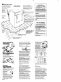
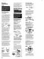
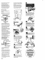
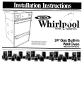
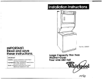
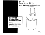
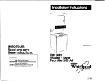
COMPACT DRYER 240 VOLT . Before you start.. . Important. Check locoi~on where dryer will be llstalled Proper instollat~on IS youi responslbllity Make sure you have everyihing necessary for correcl mtollol~on observe WARNING: Check code requirements. all governrng codes and ordinances. Potential Fire Hazard Some codes do not perml or limit ~nslollai~on of clothes dryers ln garages. closets. moblle homes. and sleeping quarters Contact our local bulldIng ~nspeclor l It is the personal responsibility ol the customer to ensure that gasoline, paint thinners and other flammable materials are not used or stored near dryer. Fumes from these materials could result in fire or explosion. l Never install dryer up against draperies or curtains. Keep any and all items from falling or collecting behind the dryer. l Replace all access or service panels before operating the dryer. Grounded eleclrical outlet 1s required See Eleclrlcal reqlllrements Open dryer door and remove literature and parts packages ihe Dryer may be exhausted from the rear See Exhaust requirements, Panel A to fully open dryer door See back SEERECESSEDAREA OR CLOSET INSTALLATION INSTRUCTIONS ON BACK COVER. vel floor: maximum slope der g!k dryer 1 Inch r I ) For Your Safety: 1 l Do not exhaust dryer into a chimney, furnace cold air duct, attic or crawl space, or any other duct used for venting. Accumulated lint could become a fire hazard or moisture could cause damage. l The exhaust system should be cleaned at least once every 2 years. l Flexible duct should never be installed concealed in wall, ceiling or floor. Protectron from weather: Propel operation of the dryer requires temperatures above 45 F Tools needed for creates greater back pressur than other hood types.1 The Exhaust Outlet is located at the bottom center of the dryer. avaIlable from your WhIrlpool dealer See Recessed area or closet installation InstructIons on back cover for adequate unobstructed air openrng requirements. Mobile home instatlation Exhaust Hoods with magnetic should latches not be used. Maxlmum length of the exhaust system depends upon the type of duct used. number of elbows and type of exhaust heed The maximum length for both rigid and flexible duct is shown in chart .,- Mabile Home Exhaust Requirements: Parts supplied for installatron Remove parts from packages that all parts were included. Check the dryer must have an outside exhaust If the dryer is exhausted through the floor and the area under the mobile home is enclosed. the exhaust system must terminate outside the enclosed area Extension beyond the enclosure will prevent lint and moisture buildup under the moblle home tf the dryer is Installed in a confined orea such as a bedroom, bathroom, to the closet. It must be exhausted Exhaust requirements WARNING: Potential Fire Hazard Metal, flexible duct may be used. Do Not use non-metal flexible duct since il is a potent101 fire hazard. Four-inch metal exhaust duct IS required. Use Duct Tape to seal all~oints Exhauslina the dryer outside IS recommended Acloset lnstollat!on fTIUSt be exhausted outside Recessed Installation that IS not exhausted outside must use Exhaust Defleclor Kit. Part No 346001 Panel A or outslde and provisions must be made for enough air for combustion and ventllatlon. (Check governing codes and ordinances ] Also. refer to the Recessed area or closet rnstallotion lnstr”ctlons The Exhaust Duct can be routed up. down. left right or straight out the back of the dryer. Detailed space reauirements can be found in Recessed area or closet lnstallotlon instructlons on back cover and on the label on the back panel of the dryer Metal, Flexible Duct must be fully extended and supported when the dryer is in its final position. DO NOT KINK OR CRUSH THE DUCT An Exhaust Hood should cap the exhaust duct to prevent exhausted air from returning Into dryer. The outlet of the hood must be at least 12 Inches from the ground or any object that may be In the path of the exhaust 2%inch outlet Exhaust Hood may be used only with short systems [Thus outlet WARNING: Potential Exhaust Systems longer Fire Hazard than specrfled will. l Accumulate Ilnt. . Shorten the lrfe of the dryer. l Reduce the performance - cause longerdving times and increase energy usage. For Exhaust Systems not covered by the exhaust length chart. see WhIrlpool Service Manual. Exhaustina WhirlDo m, Part No. 603197. available from your Whirlpool ports distributor The back pressure in any exhaust system used musl not exceed 0.3 inches of water column. measured with an Incline manometer.ot the point that the exhaust system connects to the dryer. Far permanent Installations. a stationary exhaust system IS required. Electrical requirements Electrical ground is required on this appliance. upturned ends on dryer end. terminahng I” a NEMA Tvpe 14.30P plug on supply end The fourth [groundlng] conductor must be ldentlfled by a green or green/yellow cover and the neutral conductor by a white cover Cord should be Type SRD or SRDT, with a U L -I!sted strain relief and be at least four feet long The power supply cord and strain relief are not provided with the dryer Alternate electrical connection Do not modlfy Ihe plug with the applianceif II will not 111Ihe outlet, have a proper outlet installed by a aualified electrlcian. 1. A three-wire. single phase, 120/240-volt. 60.Hz. AC only. electrical supply (or threewe. 120/208-volt if soeclfled on nameplate] IS required on a separate. 30.ampere circuit. fused on bolh sides of the Ilne. (Time-delav fuse orclrcult breaker is recomm&ded.) Do Not have a fuse I” the neutral or grounding circuit It IS the personal responsibility of the customer to contact a quallfied installer to assure that the electrlcal lnstallatlon IS adequate and in conformance with the NatIonal Electrical Code ANSI/NFPA 70-latest edItIon. and all local codes and ordinances &wire receplacie 2. This dryer IS Recep’oc’e equipped with a 30-amp-rated.t’“~30R1 flexible-type. power supply cord (pigtall). Where Flgure 1 local codes permit, It must be plugged inlo a mating. 30.amp receptacle [NEMA Type IO-30R]. [See Figure I.] Do Not use an extension cord 3. IF THE POWER SUPPLY CORD IS REMOVED. THE DRYER MUST BE CONNECTED WITH IO-GAUGE COPPER WIRE ONLY (See Panel 8. ‘Xllernate electrical connection:’ for detailed Instructlo”s.] 4. When removing the power supply cord [plgtall). Ihe appliance may be connected directly to the fused disconnect or circuit breaker box through flexible armored or non-metallic sheathed copper cable. Allow two or three feet of slack in the line between Ihe wall and the appliance so that it can be moved If servicing is evernecessary A I/:‘: U.L.-listed conduit connector must be provided at each end of the power supply cable (at the appliance and at the Iunction box1 WIresizes (COPPER WIRE ONLY] and connectIons mu? conform with the rating of the appliance [30 amperes] 5. For mobile home Installation, the 3.wire. power supply cord must be removed and the appliance wiring must be revised. The appliance cabinet must not be connected to the neutral terminal, but must be connected to the grounding wire [green] of the power supply cord. (See Panel C. “Alternate electrlcal connection” under “Mobile home Installation:’ for detalled instruclions.] Electrical ground is required on this appliance. Direct wiring connection 1, Strip the outer covenng back 3 Inches from the end exposing the three wires. 2. Strip the insulation back I inch from the end of each wire. Form the bare wires Into a “U” shaped hook Figure 5 3. Loosen. do not remove, screws from terminal block. Attach wires according fnoe;;tru$ons for type of connection 4. Slide the end of each wire under the screw head with the open side of the screw hook on the right. Squeeze the wfre together to form a loop. 5. Tighten each screw firmly Do not modify the plug wilh the applianceif It will nol fll Ihe outlet, have a proper outlel installed by a aualified electrician. This appliance IS manufactured with the neutral cabinet terminal connected Figure 6 to the When local codes... To connect a separate grounding wire: Use grounding wire and clamp assembly (Parl No 6854631 or No 10 gauge nxn~rnum copper grounding wire Connect grounding wire to a grounded coldwater pbe’ with the clamp and then to the external grounding connector on the dryer Do A. Permit use of a flexible type power supply cord (pigtail) that comes equipped with the dryer but Do Not Permll connecting the cabinetgrounding conductor to the neutral wire of Ihe power supply cord connect zaporate coppe, g’oundlng w,,e mm erternol growdIng conneclor to approved groouma no1 ground to a gas supply pipe or hot water Dbe. Do not connect the Dower suppli&ord to electric powersiPPlv until the appliance is permanently grounded Ungrounded neutml Figure 7 1. Remove terminal block cover 2. Remove the grounding wire (green) from the internal grounding connector and fasten under center, silver-colored terminal block screw. See Figure 7. 3. Connect a separate copier aroundina wire INo. 10 minimum1 See ‘To con&t a separate groundihg wire: Panel B for detailed instructions. 4. Replace the terminal block cover When local codes... Foznove Disconnect 1. Remove the power supply the power supply. Ihe terminal block cover from the dryer. 2. Disconnect the power supply cord from the terminal block 3. Use a screwdriver to slide the strain relief clip away from the power supply cord (See Figure41. 4. Pull downward on the power supply cord until it is removed from the dryer, 8. Do Not Permit the use of the flexible power supply dryer and Permit copper cord equipped power supply with the cable and Permit connecting cabinet-grounding conductor to the neutral wire of the power supply cable: Grounded neutml Figure 8 When a four-wire receptacle of NEMA Type 14.30R IS used [see Figure 21. a maiching 240.volt minimum, 30.ampere. U L -lIsled dryer power supply cord (pigtall) kit must be used. This cord contains four, No -10 copper conductors with ring terminals or spade terminals with Panel B 1. Remove the power cord equipped with the dryer as instructed. See “To remove the power supply cord:’ Panel 2. Attach a U.L.-#ted conduit connector to the dryer through the power supply B cord hole TIghten condull conneciorto cabsnet Inseri power supply cable through conduit connector 3. Connect the neutral wire of the flexlole armored or nonmetalllc sheathed copper power supply cable to the center, silver-colored termlnol of the temxnol block Connect the other wires to the outer terminals See Figure 8 For connecting plan-end wires. see “Direct wire connectlon:’ Panel Et 4. Replace the terminal block cover 4. Connect the grounding wire (green) of the copper four-wire power supply cord or cable lo the exiernol QrOUndlnQ connector 5. Connect the neutral [whlte] of the power supply cord or cable to the center, sliver-colored terminal screw of the terminal block. Connect the other wires to the outer terminals. See Figure 10 For connecting plain-end wires, see “Direct wire connectlon:’ Panel 8. 6. Replace the terminal block cover. 6- W Now stand the drver Up. When local codes. C. Do Not Permit the use of the flexible power supply cord equipped with the dryer and Permit copper power supply cable and Move the dryer to its wrmanent location. To make sure the drver is level. take a CarDenter’S i&i1 and place it on the top of ihe dryer. first side to side. then front to back. If the drver is not level. screw the leas of the d&erupordowntoodjus - Do Not Permit connecting the cabinetgrounding conductor t0 the neutral wire of the powersupplycable. Ungrounded Mobile home or other four-wire installation Four-wire power kit or o four-wire 8. neutml Figure 9 I, Remove the power supply cord equipped with the dryeros Instructed. See “To remove the power supply cord:’ Panel 8. 2. Attach CI U.L.-listed conduit connector to the dryer through the power supply cord hole. Tighten condull connector to cabinet Insert power supply cable through conduit connector 3. Remove the grounding wire (green] from the external QrOUnd?IQ cotinector and fasten under center, sliver-colored term\& block screw 4. Connect the neutral wire 01 the flexible armored or nonmetallic sheathed copper power supply cable to the center, silver-colored terminal of terminal block. Connect the other wires to the outer terminals See Figure 9. For connecting plain-end wires. see “Direct wire connection:’ Panel 8. 5. Connect 0 separate copper aroundlna wire INo 10 mlnlmuml See “To con&to s¶te grour&g wire: Panel 8. for detailed Instructions 6. Replace the terminal block cover. supply cord (pIgtail) cable is required. To exhaust the dryer. see “Exhaust requirements:’ Panel A. Remove the wire exhaust guard located at the exhaust outlet. Connect exhaust duct lo exhaust hood. Use duct tape to seal all joints in the exhaust duct. Use caulking comoound lo seal exterior wall opening around exhaust hood. nm 9. Carefully push 77 timer knob Into ~ place on the timer shaft at the front of the dryer. 2 \ 10 Check that all parts ore now W installed. See parts list. Panel A. If there IS on extra part. go back through the steps to see which step was ski&. Remove the tape that holds the drum to the cabinet. [Some dryer drums ore not taped for shipping ] Move the drum bv hand to make ceftaln all tape has been removed Wipe the Interior of the drum thoroughly with CI damp cloth before using the dryer. Remove tape from lint screen n Take two of the cardboard corners from the cation and place them on the floor to tiaht side of ihe dryer. w Figure 10 I. Remove the power supply cord equipped with the dryer OS Instructed. See Panel 8. “To remove the power supply cord” 2. Attach o U.L -lIsted strain relief to the dryer through the power supply cord hole TIghten strain relief to cabinet Insert power supply cord through the stroln rellel If using four-wire cable, attach Q UL listed conduit connector to the dryer through the power supply cord hole Tighten conduit connector to cabinet Inseri power supply cable through conduit connector. 3. Remove the grounding wire (green) IlOfT the etiernal QrOUndlnQ COnneCtOr ond fasten under center silver-colored lermlnol block screw Panel C 4 Stand in front of dryer Firmly W grasp the body of the dryer and gently lay It right side down on the cardboard corners Check that you have n tools that you started all the with. new WhIrlpool compact To gel the mosl efflclent use tram your new dryer, read your WhIrlpool Use and Care Guide. 5 Start to screw the legs into the A lIttIe liquid deteraent to lubricate the screw will help. fise an adjustable wrench to finish turning the legs unhl you have 1”of the leg below the base n holes by hand nearby where you can reter to them. The Inshuctlons will make reInstallIng ywr Whliipo~l dryer In another home as OSthe lest Recessed area or ‘closet installation ns~~~” IIYl.-nll”“.31cI ,II~,V,.“..“.. . ..“<. ,.I. use only the rear exhaust position and Exhaust Detlector Kit, Part No. 3460M is required. --t Recessed This dryer may be Installed in a recessed area or closet. The installation spacing is in inches and is minimum allowable. Additional spacing should be considered for ease of installation and servicing. If o closet door is installed, the minimum unobstructed air openings in top and bottom are required. Louvered doors with equivalent air openings are acceptable. Unobstructed air openings are required for foundry equipment when the door is installed. Minimum installation spacing Note: if recessed installation is exhausted, all swcina - can be 0: Closet Closet lnstollatlon g “,. . ..- be exhausted. appliance or hardboard This compact dryer may be installed with the compact washer companion appliance using one of the Stack Stand Kits, Part No. 695570,3390175 (white] or 3390196 (almond). The electric dryer may also use Wall Mount Kit, Part No. 345994. Do Not use in mobile home, Side View ‘3* are provided when Inslolled Front View on Stack I Stand. Product dimensions . ..- -.,-.‘.. to prevent damage to prevent to damage. Check to be sure that: A. Electric supply is connected. B. Fuse is intact and tight. C. Door is closed D. Controls are set in a running or “ON” position. E. Start button has been pushed firmly. During the normal business hours, the Whirlpool COOL-LINE@ Service will answer any questions about operating and maintaining your dryer not covered in your Operating Instructions. The Whirlpool COOL-LINE@ Service number is [SOO) 253-1301. Dial just OS you normally dial long distance-the call is free. TO PREVENT LARGE AMOUNTS OF LINT AND MOISTURE FROM ACCUMULATING AND TO MAINTAIN EFFICIENCY, THIS DRYER MUST BE EXHAUSTED OUTDOORS. Part No. 3390353 Rev B 01990 Whirlpool Corporation . . . s If the dryer does not operate properly... 24 sq. Companion appliance spacing should be considered. Detailed space requirements are located on the label on back panel of the dryer. . Shut off electric supply to dryer. l Disconnect electrical cord and tape cord securely to dryer: or have a licensed electrician disconnect the power supply cable from the fused disconnect box or dryer. l Tape the drum to the front panel. l Tape the dryer door and the lint screen. l Make sure leveling legs are screwed all the way in. Before installing your electric compact dryer in your new home, check with CI licensed electrician to confirm that the supply voltage matches the voltage specified on the nameplate. l Prepared by Whirlpool Corporation. Benton Harbor. Michigan 49022. Printed in U.S.A