1
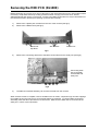
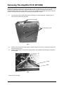
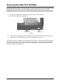
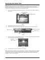
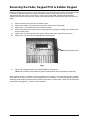
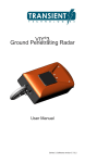
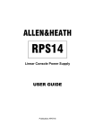
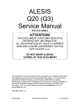
SERVICE MANUAL
Publication: AP3319
CONTENTS
Introduction, Service and Technical Support ............................................................................... 3
The icon series & Options ........................................................................................................... 4
Specifications and Connections................................................................................................... 5
Opening up the DL1000 console ................................................................................................. 6
Opening up the DP1000 console ................................................................................................. 7
Removing the DL1000 Power Supply circuit board assembly ..................................................... 8
Removing the DL1000 MIDI circuit board assembly.................................................................... 9
Removing the DP1000 Amplifier circuit board assembly............................................................. 10
Removing the DP1000 Amplifier circuit board assembly continued ............................................ 11
Removing the DP1000 Transformer and Transformer Mains wiring ........................................... 12
Removing the DP1000 MIDI circuit board assembly ................................................................... 13
Removing the CPU circuit board assembly ................................................................................. 14
Removing the LCD module.......................................................................................................... 15
Removing the Audio circuit board assembly................................................................................ 16
Removing the Fader, Keypad circuit board assembly and Rubber Keypad ................................ 17
Ordering an icon console, options, manuals and support documentation .................................. 18
Ordering an Assembly ................................................................................................................. 19
Ordering a Spares Kit .................................................................................................................. 20-22
DL1000 Front & Rear Panel drawings ......................................................................................... 23
DP1000 Front & Rear Panel drawings......................................................................................... 24
icon Block Diagram ..................................................................................................................... 25
DL1000 Power Supply Circuit Board component Ident................................................................ AG3446
DL1000 Power Supply Circuit Diagram ....................................................................................... C3446
icon MIDI Circuit Board component Ident ...................................................................................
AG3280
SCHEMATICS
icon MIDI Circuit Diagram ...........................................................................................................
C3280
PUBLISHED
DP1000 Amplifier Circuit Board component Ident .......................................................................
AG3297
SEPARATELY
DP1000 Amplifier Circuit Diagram Pages 1 to 3.......................................................................... C3297
icon CPU Circuit Board component Ident ................................................................................... AG3292
PSU SCHEMATICS
icon CPU Circuit Diagram Pages 1 to 7......................................................................................
C3292
ONLY SHOWN IN
icon Audio Circuit Board component Ident..................................................................................
AG3293
icon Audio Circuit Diagram Pages 1 to 4 ....................................................................................
SERVICE /DISTRIBUTOR C3293
icon Fader Circuit Board component Ident .................................................................................
AG3279
VERSION
icon Fader Circuit Diagram ......................................................................................................... C3279
icon Keypad Circuit Board component Ident............................................................................... AG3278
icon Keypad Circuit Diagram Pages 1 to 2 ................................................................................. C3278
DL1000 Mains Circuit Board component Ident ............................................................................ AG3298
DL1000 Mains Circuit Diagram .................................................................................................... C3298
Warning to the Service Engineer
Allen & Heath warns that any unauthorised changes or modifications to the icon unit may
invalidate the legal compliance of the unit and could void the user’s authority to operate the
equipment.
icon Service Manual AP3319 Issue 1. Copyright © 1999 Allen & Heath. All rights reserved.
MANUFACTURED IN ENGLAND BY:
ALLEN & HEATH AGENT:
ALLEN & HEATH
Kernick Industrial Estate
Penryn, Cornwall, TR10 9LU. UK
http://www.allen-heath.com
2
icon series
Introduction
The information presented in this section of the manual is intended for competent technical personnel to
carry out service and product support for the icon series. We assume that the reader is familiar with
the related electronic theory and audio terminology, and is able to carry out basic servicing, fault-finding
and repair of digital audio equipment of this type. Service personnel should also be familiar with audio
systems, mains earthing and power requirements, as well as handling precautions.
For information on the installation, operation and application of the icon series please refer to
the User Guide.
Whilst we believe the information in this manual to be reliable we do not assume responsibility for
inaccuracies. We also reserve the right to make changes in the interest of further product development.
Service and Technical Support
Under normal operating conditions the icon does not require user maintenance or internal calibration.
Any service work required should be carried out by qualified technical personnel only.
We are able to offer further product support through our world-wide distribution network. To help us
provide an efficient service please quote the unit serial number, the date and place of purchase in any
communication regarding this product.
SAFETY WARNING!
Mains electricity is dangerous and can kill. Mains voltage is
present within the console power supply unit.
The internal power supply unit contains no serviceable
components and must be replaced as a complete unit if a failure
occurs.
Do not remove the power supply cover with mains electricity
connected. To ensure your safety, mains earth is connected to
the chassis through the power lead. Do not remove this mains
earth connection.
To avoid the risk of fire, replace the mains fuse only with the
correct value and type as indicated on the power supply unit.
WARNING: There is danger of explosion if the battery is incorrectly replaced.
Replace the battery with an Allen & Heath recommended part. Using a different battery, recharging or
disassembling the battery may present a danger due to fire or explosion.
Dispose of used batteries promptly according to the manufacturer’s instructions. Keep all batteries
away from children.
IMPORTANT STATIC ELECTRICITY PRECAUTIONS
Many of the components in the icon are extremely sensitive to static electricity. The following
procedures reduce the possibility of damaging components:
1)
Before handling any components or touching anything inside the unit, discharge your
body’s static electric charge by touching a grounded (earthed) surface. Wear a grounding
wrist strap if one is available.
2)
Do not remove parts from their antistatic containers or bags until you are ready to install
them. When removing circuit boards (PCBs) or ICs from a unit, immediately place them in
an antistatic bag.
3)
When handling PCBs, hold them by their edges and avoid touching the circuitry.
4)
Do not slide PCBs or ICs over any surface.
5)
Avoid having plastic, vinyl and foam in your work area.
6)
Limiting your movements during service work reduces static electricity.
icon series
3
The ICON Series
Powered and Un-Powered Digital Live Consoles
DL1000
DP1000
10 Input Un-Powered Digital Live Mixing Console
10 Input Powered Digital Live Mixing Console
Options
DL1000-RK
AP3521
19” Rack Mount Kit for both DL1000 and DP1000 consoles
Icon Carry bag
Flightcasing the console
If the console is to be regularly moved we recommend that it is installed in a foam-lined flightcase. At all
times avoid applying excessive force to any knobs or connectors. Do not obstruct the ventilation slots or
position the icon where the air-flow required for ventilation is impeded.
Dimensions for flightcasing the console are shown below: (All dimensions in mm)
19" rack mounting
option
482 with rack ears fitted
442
MIC 48V
355
8U rack
DIMENSIONS
Unpacked
..................................... Width
DL1000 ........................ 442 (17”)
DP1000........................ 442 (17”)
..................................... Depth
DL1000 ........................ 373 (15”)
DP1000........................ 364 (14”)
..................................... Height
DL1000 ........................ 164 (6”)
DP1000........................ 162 (6”)
355
..................................... Weight (kg)
164
DL1000 ........................ 9 (20lbs)
DP1000........................ 18 (40lbs)
21
10
373
34
73
DL1000
9 kg
20 lbs
35
Packed
..................................... Width
DL1000 ........................ 550 (22”)
DP1000........................ 550 (22”)
..................................... Depth
DL1000 ........................ 505 (20”)
355
DP1000........................ 505 (20”)
..................................... Height
DP1000........................ 300 (12”)
125
162
DL1000 ........................ 300 (12”)
85
DP1000
18 kg
40 lbs
..................................... Weight (kg)
DL1000 ........................ 11 (24lbs)
15
10
DP1000........................ 20 (44lbs)
4
364
36
icon series
Specifications
0 dBu = 0.775 Volts rms 0 dBV = 1 Volt rms
HEADROOM: ........................................................ +18dBu
MAX OUTPUT:.................. JACK +18dBu 2kohm max load
CROSSTALK: Referred to driven channel @ 1kHz
Inter channel ......................................................... < -90dB
.....................LR (DL1000 ONLY) +22dBu 2kohm max load
NOISE: Measured rms 22Hz to 22kHz
.......................................PHONO +10dBu 2kohm max load
Mic input EIN (150 ohm source) .......................... < -127dB
METERS: A, B................. peak reading 10 segment LED
POWER SUPPLY: .................100 to 240V AC @ 50/60Hz
FREQUENCY RESPONSE referred to 1kHz @ 0dBu:
................. Internal, autosensing AC mains input (DL1000)
Any input to any output .................. 20Hz to 20kHz +0/-1dB
........... Internal, linear regulated AC mains input (DP1000)
DISTORTION: THD+Noise @ +14dBu 1kHz
Power consumption:.............................35W max (DL1000)
Input to Output..................................................... <0.008%
.........................................................1000W max (DP1000)
Mains Fuse rating 100-240VAC: T500mA 20mm (DL1000)
CMRR Common Mode Rejection @ 1kHz
Mains Fuse rating 100-120VAC: ......T10A 20mm (DP1000)
Mic (+40dB)........................................................... >80dB
Mains Fuse rating 220-240VAC: ........T5A 20mm (DP1000)
Connections
INPUTS:
Mic in............................. XLR .........................pin 2 hot, 3 cold, balanced ...................... 2k ohm ..........variable –55 to –8dBu
Line in ........................... TRS jack .................tip hot, ring cold, balanced ...................... >30k ohms ....variable –31 to +16dBu
Stereo Ch Mic in............ XLR .........................pin 2 hot, 3 cold balanced ....................... 2k ohm ..........variable –55 to –8dBu
Stereo Ch Line in........... TRS jack .................tip hot, ring cold, balanced ...................... >30k ohms ....variable –31 to +16dBu
Stereo Ch Phono in ....... RCA PHONO ..........unbalanced ............................................. >30k ohms ....variable –31 to +16dBu
OUTPUTS:
Aux and foldback out .....TRS jack.................tip hot, ring cold, impedance balanced..... <75 ohm ....... 0dBu
A+B Slave out ................TRS jack.................tip hot, ring cold, impedance balanced..... <75 ohm ....... 0dBu
L&R out..........................TRS jack.................tip hot, ring cold, impedance balanced..... <75 ohm ....... 0dBu
......................................or RCA PHONO......unbalanced .............................................. 600 ohm ....... -10dBV
Mono out........................TRS jack.................tip hot, ring cold, impedance balanced..... <75 ohm ....... 0dBu
A&B out (DL1000 only) ..XLR ........................pin 2 hot, 3 cold, balanced ....................... <75 ohm ....... 0dBu
Phones out ....................TRS jack.................tip left, ring right ....................................... for stereo headphones 30 to 600 Ohms
icon series
5
Opening up the DL1000 Console
Before beginning any service work, remove all power to the unit and disconnect any signal cables where
necessary. Adopt static electricity working procedures when carrying out service work. Ensure
adequate lighting and use the correct tools.
1)
2)
3)
Remove all 12 screws fixing the top panel onto the base retaining the 3 shake-proof washers
from the rear screws.
Carefully lift the top panel away from the base as the top panel is connected via IDC harnesses.
Remove the 2 IDC Harnesses from the MIDI and Power Supply PCB respectively (see fig.1)
IDC Harness
connected to
MIDI PCB
IDC Harness connected
to Power Supply PCB
(Shown Detached)
fig.1
4)
5)
Remove the M3 nylock nut and earth wires (see fig.2)
Detach the front panel from the base.
Earth Post, M3
nylock Nut and
earth wires
fig.2
Note: When Audio testing the unit make sure that the front panel and base are fixed with a chassis
screw at the rear of the console.
6
icon series
Opening up the DP1000 Console
Before beginning any service work, remove all power to the unit and disconnect any signal cables where
necessary. Adopt static electricity working procedures when carrying out service work. Ensure
adequate lighting and use the correct tools.
1)
2)
3)
4)
5)
Remove all 12 screws fixing the top panel onto the base retaining the 3 shakeproof washers
from the rear screws.
Carefully lift the top panel away from the base as the top panel is connected via IDC harnesses.
Remove the 2 IDC Harnesses from the MIDI and Amplifier PCB respectively (see fig. 3)
Remove the M3 nylock nut and earth wires (see fig.3)
Detach the front panel from the base.
IDC
Harness
connected
to MIDI
PCB
Left Earth post,
M3 Nylock Nut
and earth wires
IDC Harness connected
to Amplifier PCB
(Shown Detached)
Right Earth post
fig.3
Note: When Audio testing the unit make sure that the front panel and base are fixed with a chassis
screw at the rear of the console.
icon series
7
Removing the Power Supply PCB (DL1000)
Before beginning any service work, remove all power to the unit and disconnect any signal cables where
necessary. Adopt static electricity working procedures when carrying out service work. Ensure
adequate lighting and use the correct tools. Access to the Power Supply circuit board can only be
achieved once the console has been opened (see ‘Opening up the DL1000 console’).
1)
Turn the console base over to reveal underside. Referring to fig.4 remove the 3 heat-sink
screws.
3 heat-sink screws
fig.4
2)
3)
Remove the 2 XLR screws from the rear of the base and drill out the 2 Mains Inlet IEC pop
rivets (see fig.5)
The Power Supply circuit board assembly can now be removed from the console.
When all service work is complete, remove all debris such as solder, component legs and wire clippings
from inside the unit and check your work carefully before re-assembly. To refit the Power Supply circuit
board assembly, follow the above procedure in reverse order. Make sure all Earth wires are aligned and
plugged on. Test for correct operation.
8
icon series
Removing the MIDI PCB (DL1000)
Before beginning any service work, remove all power to the unit and disconnect any signal cables where
necessary. Adopt static electricity working procedures when carrying out service work. Ensure
adequate lighting and use the correct tools. Access to the MIDI circuit board can only be achieved once
the console has been opened (see ‘Opening up the DL1000 console’).
1)
2)
Remove the 4 plastic jack sockets from the rear of the console (see fig.5)
Remove the 2 RS232 nuts (see fig.5)
Mains Inlet
Pop Rivet
Jack Sockets
RS232 nuts
fig.5
3)
Remove the connecting earth wire to the MIDI circuit board from the earth post (see fig.6)
Connecting earth
wire to the MIDI
circuit board and
earth post
fig.6
4)
The MIDI circuit board assembly can now be removed from the console.
When all service work is complete, remove all debris such as solder, component legs and wire clippings
from inside the unit and check your work carefully before re-assembly. To refit the MIDI circuit board
assembly, follow the above procedure in reverse order. Make sure the Earth wire is connected to the
earth post. Test for correct operation.
icon series
9
Removing The Amplifier PCB (DP1000)
Before beginning any service work, remove all power to the unit and disconnect any signal cables where
necessary. Adopt static electricity working procedures when carrying out service work. Ensure
adequate lighting and use the correct tools. Access to the Amplifier circuit board can only be achieved
once the console has been opened (see ‘Opening up the DP1000 console’).
1)
Turn the base onto its side (supporting if necessary) to reveal underside. Referring to fig.7
remove the 5 screws from the base.
4 Heat-sink screws
5 underside screws
fig.7
2)
3)
Place the unit so that it is upright again. Referring to fig.7 remove the 4 heat-sink screws from
the side of the console.
Using Long-nose pliers, squeeze the joining pillar in the Amplifier PCB (see fig.8) to release it
from the PCB.
Toroid
Pillar
fig.8
Continued on next page.
10
icon series
Removing The Amplifier PCB (DP1000) cont.
4)
®
Remove the plastic snap-in rivets from the rear Speakon connectors (see fig.9)
Plastic Snap-In Rivets
fig.9
5)
6)
The Amplifier circuit board assembly and connecting Heat-sink can now be removed from the
console, but remains attached to the transformer and earth post.
If replacing the Amplifier circuit board assembly then de-solder the transformer wires and green
earth wire from the left earth post (see fig.3) at the PCB.
When all service work is complete, remove all debris such as solder, component legs and wire clippings
from inside the unit and check your work carefully before re-assembly. To refit the Amplifier circuit board
assembly, follow the above procedure in reverse order. Make sure all harnesses are aligned and
plugged on. Test for correct operation.
Torque measurement for power components
When replacing any of the 8 power transistors seated on the heat-sink, it is necessary to tighten the
fixing nuts using a torque wrench to 1N/m (one Newton metre).
icon series
11
Removing the Toroid Transformer (DP1000)
Before beginning any service work, remove all power to the unit and disconnect any signal cables where
necessary. Adopt static electricity working procedures when carrying out service work. Ensure
adequate lighting and use the correct tools. Access to the Toroid Transformer can only be achieved
once the Amplifier circuit board has been removed (see ‘Removing the Amplifier Circuit Board
Assembly’).
1) Referring to fig.10 remove the Toroid Transformer bolt.
Toroid Transformer Bolt
fig.10
2) Referring to fig.11, de-solder all transformer wires from the Amplifier circuit board and remove the
green or green & yellow Transformer earth wire from the right earth post (see fig.11). Pull off the
two transformer wires connected to the Mains circuit board.
3) Remove the Toroid Transformer from the console.
To refit the Toroid Transformer, follow the above procedure in reverse order. Make sure all Transformer
wires are re-soldered correctly. Test for correct operation.
Toroid Transformer Mains Wiring
The diagram below shows the Transformer Mains wiring for different territories, when re-fitting the
transformer be sure to re-connect the wires as shown.
Mains
PCB
Voltage Primary Winding Colour
240V
220V
120V
110V
100V
Brown
Red
Black
White
Grey
Blue
0V
Live (see table
for different
territories)
Green Earth wire
Green or
Green/Yellow
Transformer
Earth screen
Amplifier
PCB
Toroid
Transformer
Brown
16.5V
Blue White
16.5V 0V
Red Red Green Orange Black Yellow
0V
9V
42.7V 42.7V
Earth 0V
fig.11
12
icon series
Removing the MIDI PCB (DP1000)
Before beginning any service work, remove all power to the unit and disconnect any signal cables where
necessary. Adopt static electricity working procedures when carrying out service work. Ensure
adequate lighting and use the correct tools. Access to the MIDI circuit board can only be achieved once
the Amplifier circuit board assembly is removed (see ‘Removing the Amplifier Circuit Board Assembly’).
1)
2)
Remove the 4 plastic jack sockets from the rear of the console (see fig.12)
Remove the 2 RS232 nuts (see fig.12)
Jack Sockets
RS232 nuts
fig.12
3)
4)
Remove the connecting earth wire to the MIDI circuit board from the left earth post (see fig.3)
The MIDI circuit board assembly can now be removed from the console.
When all service work is complete, remove all debris such as solder, component legs and wire clippings
from inside the unit and check your work carefully before re-assembly. To refit the MIDI circuit board
assembly, follow the above procedure in reverse order. Make sure the Earth wire is connected to the
earth post. Test for correct operation.
icon series
13
Removing the CPU PCB
Before beginning any service work, remove all power to the unit and disconnect any signal cables where
necessary. Adopt static electricity working procedures when carrying out service work. Ensure
adequate lighting and use the correct tools. Access to the CPU circuit board can only be achieved once
the console has been opened (see ‘Opening up the DL/DP1000 console’)
1)
Remove the 10 rotary encoder knob caps (see fig.13)
Rotary Knobs
fig.13
2)
3)
4)
Remove the 4 nuts from the Audio Shield (see fig.14), retaining the crinkle washer. Remove
Audio shield.
Remove the 7 screws from the CPU circuit board (see fig.14)
Remove the 2 connecting IDC Harnesses from the CPU circuit board and cut the connecting
cable tie (see fig.14)
Audio Shield Nuts
Audio Shield
Cable Tie
CPU PCB
CPU to chassis screws
fig.14
5)
6)
Detach all other cables and harnesses from the CPU circuit board (note: the CPU to Fader IDC
is siliconed on at the CPU circuit board, the silicone bond will have to be broken to release the
CPU to Fader IDC)
The CPU circuit board assembly can now be removed from the console.
When all service work is complete, remove all debris such as solder, component legs and wire clippings
from inside the unit and check your work carefully before re-assembly. To refit the CPU circuit board
assembly, follow the above procedure in reverse order. Make sure all harnesses are aligned and
plugged on. Test for correct operation.
14
icon series
Removing the LCD Module
Before beginning any service work, remove all power to the unit and disconnect any signal cables where
necessary. Adopt static electricity working procedures when carrying out service work. Ensure
adequate lighting and use the correct tools. Access to the LCD module can only be achieved once the
CPU circuit board has been removed (see ‘Removing the CPU PCB’)
1)
Remove the 3 screws attaching the CPU PCB onto the LCD module (see fig.15)
CPU to LCD module screws
M3 Screw and
Shake-proof washer
Ribbon connector pins
fig.15
2)
Flip the CPU circuit board over and remove the M3 nylock nut, earth wire and then remove the
M3 half-nut (see fig.16)
Earth wire
M3 Nylock Nut
and Half-nut
fig.16
3)
4)
5)
Carefully de-solder the ribbon connector pins (see fig.15) and remove ribbon connector from the
LCD module.
Retain the M3x25 screw with shake-proof washer and pillar once removed (see fig.15)
The LCD module can now be removed from the CPU circuit board assembly.
To refit the LCD module, follow the above procedure in reverse order. Make sure all harnesses are
aligned and plugged on. Test for correct operation.
icon series
15
Removing the Audio PCB
Before beginning any service work, remove all power to the unit and disconnect any signal cables where
necessary. Adopt static electricity working procedures when carrying out service work. Ensure
adequate lighting and use the correct tools. Access to the Audio PCB can only be achieved once the
console has been opened (see ‘Opening up the DL/DP1000 console’)
1)
Remove the 4 nuts from the Audio Shield (see fig.17), retaining the crinkle washer. Remove
Audio shield.
Audio Shield Nuts
Audio Shield
fig.17
2)
3)
Detach all harnesses from the Audio circuit board.
Remove the plastic jack sockets, XLR and Phono screws from the rear panel (see fig.18)
Plastic Jack Sockets
Phono Screws
XLR Screws
fig.18
4)
Working from the top of the console remove the 11 knob caps. Once the knob caps have been
removed then remove the pot nuts (see fig.19).
Knob caps
and Pot. Nuts
fig.19
5)
The Audio PCB can now be removed from the console.
When all service work is complete, remove all debris such as solder, component legs and wire clippings
from inside the unit and check your work carefully before re-assembly. To refit the Audio circuit board
assembly, follow the above procedure in reverse order. Make sure all harnesses are aligned and
plugged on. Test for correct operation.
16
icon series
Removing the Fader, Keypad PCB & Rubber Keypad
Before beginning any service work, remove all power to the unit and disconnect any signal cables where
necessary. Adopt static electricity working procedures when carrying out service work. Ensure
adequate lighting and use the correct tools. Access to the Fader PCB, Keypad PCB and Rubber
Keypad can only be achieved once the CPU circuit board has been removed (see ‘Removing the CPU
PCB’)
1)
2)
3)
4)
5)
6)
Remove all front panel gain pot. and fader knobs.
Remove the 8 fader screws from the front panel. Remove the Fader PCB.
Remove the 11 potentiometer nuts from the front panel.
Remove the plastic jack sockets from the rear panel by turning them 45deg anti-clockwise and
then pull off by hand.
Remove the 11 screws from the rear panel. Remove the Audio PCB from the console.
Remove the 3 screws from the Keypad Bracket (see fig.20)
Keypad bracket screws
fig.20
7)
Remove the Keypad bracket, the Keypad PCB then the Keypad.
(Note: We recommend the Rubber Keypad is replaced when the Keypad PCB is replaced).
When all service work is complete, remove all debris such as solder, component legs and wire clippings
from inside the unit and check your work carefully before re-assembly. To refit the Keypad circuit board
assembly and/or Rubber Keypad, follow the above procedure in reverse order. Make sure all harnesses
are aligned and plugged on. Test for correct operation.
icon series
17
Ordering an Icon Console
To order a new console please specify the model number and AC mains voltage required.
MODEL
DESCRIPTION
ORDER CODE
DL1000
Unpowered icon Digital Mixing Console
DL1000/volts
DP1000
Powered icon Digital Mixing Console
DP1000/volts
Ordering an Option
To order an option please specify the serial number of the console that is to have the option fitted.
MODEL
DESCRIPTION
ORDER CODE
DL1000-RK
19” Rack Mounting Kit for DL1000 & DP1000 Consoles
DL1000-RK
Carry Bag
Polyester Icon Carry Bag
AP3521
Manuals and Support Documentation
DESCRIPTION
ORDER CODE
icon User Guide
AP3299
icon Service Manual
AP3319
icon Brochure
AP3531
icon Rack Ears Fitting Instructions
AP3577
Service Tools
The tools required to service the icon are standard to an electronic service workshop and are easily
obtainable. The following items are necessary for disassembly and service access:
1-point Crosshead screwdriver (M3, 4AB)
2-point Crosshead screwdriver (M4, 6AB)
5mm AF Nutdriver (RS232 nuts)
5.5mm AF Nutdriver (audio shield nuts)
11mm AF Nutdriver (potentiometer nuts)
12mm AF Nutdriver (jack sockets)
15mm AF Nutdriver (slimline jack sockets and Toroid Transformer bolt)
Long-nose Pliers
18
icon series
Ordering an Assembly
The following assemblies are supplied fully tested. Please quote the description and order code for the
part required.
Printed Circuit Board (PCB) Assemblies:
Audio PCB assembly
002-379
Keypad PCB assembly
002-380
Fader PCB assembly
002-381
MIDI PCB assembly
002-382
Mains PCB assembly (DP1000 only)
002-384
Amplifier/Heat-sink PCB assembly (DP1000 only)
002-385
CPU/LCD PCB assembly
002-386
PSU PCB assembly
002-445
IDC connector harnesses:
DL/DP1000
16 way MIDI harness
AL3340
DL/DP1000
20 way Audio harness
AL3341
DL/DP1000
26 way Audio harness
AL3342
DL/DP1000
26 way Switch Mode PSU harness
AL3586
icon series
19
Ordering a Spares Kit
It is recommended that the spares kit order code 002-303 is held and maintained by the service agent to
enable in-field service repairs to the icon independent of the ALLEN & HEATH factory. Commonly
available items such as resistors, capacitors, tools and soldering equipment are not included. The
contents of the kit are listed below and are supplied in a cabinet of drawers. Individual spares parts may
be ordered. Please quote the description and order code for the part required.
DESCRIPTION
ORDER CODE
QTY
AB0057
AB0062
AB0065
AB0071
AB0072
AB0073
AB0076
AB0079
AB0080
AB0094
AB0102
AB0244
AB0252
AB0270
AB0289
AB0332
AB2810
AB2811
AB3500
AB3516
AB3541
AB3558
AB3595
AB8136
AB8137
AB8168
AK8132
2
3
3
5
5
10
5
3
2
3
10
10
2
1
5
10
10
10
2
1
2
4
4
1
1
10
10
AJ2052
AJ2887
AJ3310
AJ3311
AJ3314
AJ3316
AJ3488
5
2
10
10
15
15
5
AA3514
AA3515
AA8173
AC8157
AE0048
AE0068
AE0071
AE0232
AE0239
AE0351
5
4
8
2
1
2
1
2
1
1
Fixings:
Screw 4AB x 5/16 Pan Pozi Black
Screw 6AB x 3/8 Pan Pozi Black
Screw 8AB x 3/8 Pan Pozi Zinc
Screw M3 x 6mm TT Pan Pozi Black
Screw M3 x 6mm Pan Pozi Black
Screw M3 x 8mm Pan Pozi Black
Screw M3 x 10mm Pan Pozi Black
Screw M3 x 16mm Pan Pozi Black
Screw M3 x 20mm CSK Pozi Zinc
Half Nut M3
Nylock Nut M3
Shakeproof Washer M3
Screw 4AB x ¼ Pan Pozi Plated
Nylock Nut M5
Shakeproof Washer M4
Screw M4 x 8mm Pan Pozi Black
Screw 4 x 5/16 Poly Pan Pozi Black
Screw M3 x 5mm CSK Pozi Black
Nylon Spacer M3 x 9mm
Screw M5 x 25mm Pan Pozi Zinc
Washer 1/8”
Pillar Hex Brass M3 x 5mm
Screw M3.5 x 8mm TT Pan Pozi Black
Screw M8 x 90mm Cup Square Hex
Nylock Nut M8
Nylock Nut 6-32 Zinc
Fastfoot
Knobs and Caps:
Button 5mm Square Grey
Button Round Black
Knob Soft Touch Dark Blue & Black
Knob Soft Touch Light Blue & Black
Knob Soft Touch Light Blue & Black 11mm D2
Fader Knob 11mm Light Blue+Black Line
Button 5mm Square Red
Amplifier PCB:
Insulating Kit TO220 Self Adhesive No Holes
Insulating Kit TO220 Self Adhesive
Insulating Kit T03 High Eff
Preset Resistor 500R Ceramic Horizontal
IC Regulator 7915
Transistor BC637 NPN TO92H
IC LM339N Comparator
Zener Diode BZX79C 12V 400mW
Bridge Rectifier 35A 600V
Bridge Rectifier 6A In-Line
20
icon series
Zener Diode 47V 500mW
Transistor TIP122
Thermistor 100K
Transistor MPSA92 PNP
Transistor MJ15024 NPN
Transistor MJ15025 PNP
Transistor MPSA42 NPN
Transistor 2SC2240BL NPN
Transistor MJE340 NPN
Transistor MJE350 PNP
Fuse 6.3A Anti-Surge 20mm
Fuse 1A Anti-Surge TE5
Fuse 2A Anti-Surge TE5
Fuse 16A Anti-Surge 20mm
Fan 80x80x25 12V DC
Inductor Amplifier O/P
AE2999
AE3215
AE3499
AE8119
AE8129
AE8130
AE8138
AE8152
AE8155
AE8156
AL0395
AL3529
AL3530
AL8154
AM3517
AM8146
1
1
1
15
4
4
15
2
2
2
5
3
3
5
1
2
AE3005
AE3006
AE3007
AE3040
AE3043
AE3044
AE3066
AE3132
AE3196
AE3326
AE3336
AE3454
AE3498
AI3309
AP3334
1
2
1
1
1
1
10
1
AE0139
AI3313
4
15
AE0222
AE2742
AL0095
AL2048
AL3081
2
2
2
4
1
AE0085
AE0086
AE8069
AI8003
AI8007
AI8111
AI8174
AL0328
AL2410
AL3443
AL8065
AL8114
2
2
10
2
1
5
2
1
3
1
3
10
CPU PCB:
IC MPU H8/3003
IC CS4222 20-Bit Codec
Crystal 14MHz
IC Regulator 3.3V Zetex
IC SRAM 64Kx16 15ns 3.3V Low Power
IC SRAM 32Kx8 70ns 5V Low Power
IC DS1233-5 TO92 Power Reset
LCD Module DL1000
IC DSP 56303 PV80
IC CPLD XC9572PLCC44C-15
IC XTAL OSC 11.2896MHz 100ppm
IC Flash 256Kx16 70ns
Transistor Mosfet BSS138
Encoder EC16B
Battery 2.4V 70mAh NICAD
Fader PCB:
IC CMOS 4052B
Fader 10K Linear Slimline 100mm
MIDI PCB:
IC 6N136 Opto-Isolator
IC RS232 HIN202CP
DIN Socket Female 5way 180deg PCB
Jack Socket Small
Switch Slide MINI SPDT PCB
Audio PCB:
LED 3mm T1 Green
LED 3mm T1 Red
Transistor 2SB737 PNP
Pot 20KK (203K 11mm wide)
Pot 20KK x 2 (203K 14mm wide)
Pot 5K (502RD 11mm wide)
Pot 5KRD x 2 (502RD 14mm wide)
Jack Socket Headphone
XLR 3 Pin Female Vertical PCB
Phono Socket Dual Vertical PCB 24mm
Switch 2PCO Latching 90deg
Jack Socket Vertical PCB + nut
icon series
21
Faders, Potentiometers, Switches and Connectors:
Jumper Socket 2way
Molex 0.1” Male 15 x 2 pin straight
Speakon Connector NL4MP Chassis
Jack Nut Slimline Plastic
Fuse Clip Schurter
Fuse Cover Schurter
AL0334
AL3583
AL8126
AL8133
AL8134
AL8139
1
1
2
4
5
2
AE0020
AE0046
AE0047
AE3001
15
4
2
5
AE0266
AE0308
AE2818
AE3469
AE3470
AE3471
AE3472
AE3473
AE3475
AE3477
AE3478
AE3588
AE3589
AE8143
AH0205
AH0206
AH0323
AL2270
AL2413
AL3178
AL3338
AL3447
AL3455
AL3458
AL3534
AM2970
AM3084
AM3467
AM3476
4
1
10
1
1
1
10
10
-
002-374
AA0693
AA3259
AH2228
2
2
Common Semiconductors:
Transistor BC549 NPN
IC TL072 Op-Amp
IC Regulator 7815
Transistor BC556B PNP
Power Supply:
IC 4N35 Opto-Isolator (DL1000)
IC Regulator 7805
IC Comparator LM393N (DL1000)
Diode BYV27-400 2A 400V (DL1000)
Diode BYV26E 1A 1000V (DL1000)
Diode P6KE200A (DL1000)
Transistor Mosfet STP4NA80FI (DL1000)
IC SMPS UC3842AN (DL1000)
IC TL431 Voltage Reference (DL1000)
Bridge Rectifier 2KBP06M (DL1000)
Inrush Supressor 20R (DL1000)
IC Regulator 7812 (DL1000)
IC Regulator 7912 (DL1000)
Inrush Supressor (DP1000)
Mains Lead IEC-2pin Euro
Mains Lead IEC-3pin UK
Mains Lead IEC-3pin US (C33)
Mains Fuse 20mm 5A A/Surge (DP1000)
XLR 3 Pin Male 90deg PCB (DL1000)
Fuse Holder 20mm PCB (DL1000)
Mains Switch 10A PCB
Fuse Holder 10A 20mm PCB (DP1000)
Mains Fuse 20mm 10A A/Surge (DP1000)
IEC Mains Inlet Filter PCB 3 Pin (DL1000)
Mains Fuse 20mm 500mA A/Surge (DL1000)
Inductor 150uH 280mA (DL1000)
Transformer DP1000 Toroid
Inductor 4.7uH 600mA (DL1000)
Transformer DL1000 Switch Mode
Miscellaneous:
icon Packing Assembly
Insulating Kit TO220
Rubber Keymat
Flex cable 12way 90mm
22
icon series
DL1000
GAIN
GAIN
GAIN
GAIN
GAIN
GAIN
GAIN
GAIN
MONO
MIN
MAX
MIN
MAX
MIN
MAX
MIN
MAX
MIN
MAX
MIN
MAX
LEV
MONO
MIN
MAX
LEV
STANDBY
MIC 48V
MIN
MAX
MIN
MAX
MIN
MAX
A
LIMIT
+9
+6
+3
MIN
B
L
R
FB
M
AUX
FB
-3
PERFORMANCE
RECALL
-3
-6
-6
-9
ENTER
-9
PFL
-25
COPY
EDIT
250Hz
500Hz
1kHz
2kHz
4kHz
8kHz
16kHz
HOME
VALUE
-15
-25
125Hz
RESET
0dB
-15
63Hz
UNDO
+6
+3
0dB
31Hz
ESC
MENU
PASTE
+9
MAX
UTIL
UTILITY
SET
SEQUENCE
OF
SONGS
GRAPHIC
EQ 1-8
HOME
OUT
EQ A
GATE
NOISE GATES
EQ 1
EQ 2
EQ 3
EQ 4
EQ
5
EQ
6
EQ
7
EQ 8
4 BAND PARAMETRIC EQ
FX
1
EFFECTS
FX
2
REVERB
EQ B
10 BAND GRAPHIC EQ
VENUE
MODE
MEMORY
STORE
A-B SETUP
AUX
FB
LEVEL
PAN
COMP
SENDS
FOLDBACK
TRIM
BALANCE
COMPRESSORS
SONG
CHANNEL SAFE
PEAK
PEAK
PEAK
PEAK
PEAK
PEAK
PEAK
PEAK
PEAK
PEAK
PEAK
PEAK
PEAK
PERFORM SET
6
6
6
6
6
6
6
6
0
0
0
0
0
3
3
3
3
3
3
3
3
0
0
0
0
0
0
0
0
3
3
3
3
3
6
6
6
6
6
5
5
5
5
5
5
5
5
10
10
10
10
10
10
10
10
10
10
10
10
10
15
15
15
15
15
15
15
15
15
15
15
15
15
20
20
20
20
20
20
20
20
30
30
40
30
40
30
30
40
40
30
40
40
30
20
20
20
20
30
30
30
30
40
40
40
40
40
30
40
STEREO
20
30
40
STEREO
EFFECTS
REVERB
FOLDBACK
MAIN
DO NOT OBSTRUCT VENTILATION OPENINGS.
DO NOT OPEN. NO USER SERVICEABLE PARTS INSIDE.
CAUTION
WARNING: TO REDUCE THE RISK OF ELECTRIC SHOCK DO NOT EXPOSE THIS APPARATUS TO RAIN OR MOISTURE.
THIS APPARATUS MUST BE EARTHED BY THE POWER CORD.
SEE OPERATING MANUAL BEFORE USING.
CAUTION: FOR CONTINUED PROTECTION AGAINST RISK OF FIRE REPLACE FUSE WITH SAME TYPE AND RATING.
ATTENTION: REMPLACER LE FUSIBLE AVEC UN DES MEMES CARACTERISTIQUES.
AVIS: RISQUE DE CHOC ELECTRIQUE - NE PAS OUVRIR.
MADE IN ENGLAND BY ALLEN & HEATH
A DIVISION OF HARMAN INTERNATIONAL INDUSTRIES LTD
1
MIX
LINE IN
MIX
TRS
IMPEDANCE
BALANCED
MIC
PIN2 = +
PRE-LEVEL
OUT
ON/OFF
I
icon series
0
FUSE
MAINS INPUT
T500mA
250V 20mm
100 - 240 V.AC
47-63 Hz ~ 30W MAX
SERIAL NUMBER
MAIN OUTPUT
BALANCED PIN2 = +
FOOTSWITCHES
MIDI
RS232
IN
SELECT
SERIAL PORT
23
DP1000
GAIN
GAIN
GAIN
GAIN
GAIN
GAIN
GAIN
GAIN
MONO
MIN
MAX
MIN
MAX
MIN
MAX
MIN
MAX
MIN
MAX
MIN
MAX
LEV
MONO
MIN
MAX
LEV
STANDBY
MIC 48V
MIN
MAX
MIN
MAX
MIN
MAX
MIN
MAX
PROTECT
A
LIMIT
+9
+6
+3
B
L
R
FB
M
AUX
FB
PERFORMANCE
RECALL
-3
-6
-6
-9
ENTER
-9
PFL
-15
-25
COPY
EDIT
250Hz
500Hz
1kHz
2kHz
4kHz
8kHz
16kHz
HOME
VALUE
-15
-25
125Hz
RESET
+3
0dB
-3
63Hz
UNDO
+6
0dB
31Hz
ESC
MENU
PASTE
+9
UTIL
UTILITY
SET
SEQUENCE
OF
SONGS
GRAPHIC
EQ 1-8
HOME
OUT
EQ A
GATE
NOISE GATES
EQ 1
EQ 2
EQ 3
EQ 4
EQ
5
EQ
6
EQ
EQ 8
7
4 BAND PARAMETRIC EQ
FX
1
EFFECTS
EQ B
10 BAND GRAPHIC EQ
MODE
2
AUX
FB
LEVEL
PAN
COMP
REVERB
SENDS
FOLDBACK
TRIM
BALANCE
COMPRESSORS
FX
VENUE
MEMORY
STORE
AMPLIFIER SETUP
SONG
CHANNEL SAFE
PEAK
PEAK
PEAK
PEAK
PEAK
PEAK
PEAK
PEAK
PEAK
PEAK
PEAK
PEAK
PEAK
PERFORM SET
6
6
6
6
6
6
6
6
0
0
0
0
0
3
3
3
3
3
3
3
3
0
0
0
0
0
0
0
0
3
3
3
3
3
6
6
6
6
6
10
5
5
5
5
5
5
5
5
10
10
10
10
10
10
10
10
10
10
10
10
15
15
15
15
15
15
15
15
15
15
15
15
15
20
20
20
20
20
20
20
20
20
20
20
20
20
30
30
30
30
30
30
30
30
30
30
30
30
30
40
40
40
40
40
40
40
40
40
40
40
40
40
STEREO
STEREO
EFFECTS
REVERB
FOLDBACK
MAIN
DO NOT OBSTRUCT VENTILATION OPENINGS.
DO NOT OPEN. NO USER SERVICEABLE PARTS INSIDE.
CAUTION
WARNING: TO REDUCE THE RISK OF ELECTRIC SHOCK DO NOT EXPOSE THIS APPARATUS TO RAIN OR MOISTURE.
THIS APPARATUS MUST BE EARTHED BY THE POWER CORD.
RISK OF HAZARDOUS ENERGY! MAKE PROPER SPEAKER CONNECTIONS.
SEE OPERATING MANUAL BEFORE USING.
CAUTION: FOR CONTINUED PROTECTION AGAINST RISK OF FIRE REPLACE FUSE WITH SAME TYPE AND RATING.
ATTENTION: REMPLACER LE FUSIBLE AVEC UN DES MEMES CARACTERISTIQUES.
AVIS: RISQUE DE CHOC ELECTRIQUE - NE PAS OUVRIR.
MADE IN ENGLAND BY ALLEN & HEATH
A DIVISION OF HARMAN INTERNATIONAL INDUSTRIES LTD
1
MIX
LINE IN
MIX
TRS
IMPEDANCE
BALANCED
MIC
PIN2 = +
ON/OFF
I
24
0
FUSE
MAINS INPUT
100-120V T10A
220-240V T5A
AC ONLY ~ 47- 63 Hz
1000W MAX
V.AC
SERIAL NUMBER
SPEAKER OUTPUTS
300W + 300W RMS
4 OHM LOAD MINIMUM
PIN 1+ 1-
FOOTSWITCHES
MIDI
RS232
IN
SELECT
SERIAL PORT
icon series
icon series
25
L
R
GLOBAL
PRE/POST
AUX
FB
FX1 L
R
FX2
PFL
L
R
TRIM
FADER
MUTE
PAN
PRE
AUX FX2
FB
FX1
TRIM
FADER
MUTE
BAL
MIC
FB
FX1
PEAK
CH 7-8
STEREO
AUX FX2
R
PRE
PFL
PFL
PEAK
COMPRESSOR
COMPRESSOR
ADC
GAIN
MONO
LINE 2
LINE 1
NOISE GATE
ADC
L
NOISE GATE
CH 1-6
MONO
GAIN
+
MIX
4 BAND EQ
ADC
MIC
4 BAND EQ
LINE
TRIM
FADER
MUTE
R
L
BAL
FB
AUX FX2
PRE
PFL
INSERTION EFFECTS
FX1
MIC 48V ON
FX1
PEAK
TRIM
FADER
MUTE
BAL
FB
AUX FX2
PRE
PFL
REVERB EFFECTS
FX2
FX1
PEAK
BLOCK DIAGRAM
PFL
PFL
PFL
METERS
A
B
DAC
PEAK
PEAK
PEAK
PFL
+
DAC
MUTE
LR
MUTE
AUX
MUTE
FB
LEVEL
HEADPHONES
-
-
LINE OUT
B
DL1000
A
DAC
FB
+
LR SUM
+
DAC
AUX
AMPLIFIER
SPEAKER
A
L
R
MONO
10 BAND
GRAPHIC EQ
SOURCE SELECT
FB AUX
B
LEVEL
DAC
B
PROTECTION
LIMITER
B
AB
10 BAND
GRAPHIC EQ
PROTECTION
LIMITER
A
SLAVE
LEVEL
DAC
A
DAC
MONO
DAC
L
L
STANDBY
DP1000
HI
LO
R
DAC
R