1
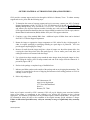
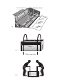
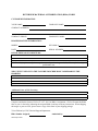
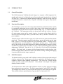
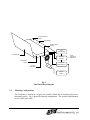
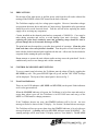
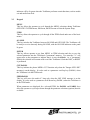
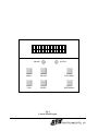
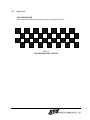
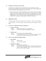
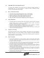
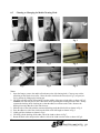
User Manual
October 2001
P/N 614-105223
This page is deliberately blank
~ COPYRIGHT NOTICE ~
This document is copyrighted by OYO Instruments, LP. No part of this publication may be
reproduced, transmitted, transcribed, stored in a retrieval system, or translated into any language or
computer language in any form or by any means, electronic, manual, or otherwise, without written
permission of OYO Instruments, LP, 9777 W. Gulf Bank, Suite 10, Houston, Texas 77040, U.S.A.
Copyright violators may also be subject to civil penalties.
~ DISCLAIMER ~
OYO Instruments, LP makes no warranties as to the accuracy, validity, or fitness for use of the
contents of this Manual. OYO Instruments, LP reserves the right to revise the information in this
Manual at any time without prior notice.
OYO Instruments, LP
9777 W. Gulf Bank, Suite 10, Houston, Texas 77040 U.S.A.
Telephone: 800-747-7651
Telephone: 713-937-5800
Telefax: 713-849-3022
EUROPE - OYO Instruments, Europe Ltd.
F3 Bramingham Business Park, Enterprise Way,
Luton, Bedfordshire LU3 4BU, U.K.
Telephone: 44-1582-573980
Telefax: 44-1582-574945
CANADA - OYO GeoSpace, Canada, Inc.
2735 - 37th Ave N.E., Calgary, Alberta, Canada TIY 5R8
Telephone: 403-250-9600
Telefax: 403-250-9643
May 2001
This page is deliberately blank
~ STATEMENT OF LIMITED WARRANTY ~
OYO Instruments, LP (“OYO”) warrants its imagers (excluding print heads) for twelve (12) months. OYO
warrants its print heads for three (3) months. The purchaser of the imager may extend the print head
warranty to twelve (12) months via the execution of a film supply contract.
This warranty commences on the date of original shipment from OYO. Any part of the imager
manufactured or supplied by OYO and found in reasonable judgment by OYO to be defective in material or
workmanship will be repaired or replaced by an OYO authorized service center without charge for parts and
labor.
To obtain warranty coverage, a Return Material Authorization (RMA) number must be obtained and the
imager, including any defective parts, must be returned to an authorized service center within the warranty
period. Failure to follow the RMA procedure may void the warranty.
This warranty does not cover any imager that has been subject to misuse, neglect, negligence, accident, or
any imager that has been operated in any way contrary to the imager cleaning procedures (as specified in
the OYO Operator’s Manual). This warranty does not apply to damage resulting from improper
maintenance or from damage caused by imager modifications made by user.
This warranty does not extend to repairs made necessary by (i) normal wear or (ii) by the use of parts,
accessories, or media not distributed by OYO. The use of such uncertified items, especially media, may
adversely affect the imager’s operation, performance or durability and therefore void this warranty.
OYO reserves the right to change or improve the design of any imager without assuming any obligation to
modify any product previously manufactured.
ALL IMPLIED WARRANTIES ARE LIMITED IN DURATION TO THE APPLICABLE WARRANTY PERIOD.
ANY SUCH IMPLIED WARRANTIES INCLUDING MERCHANTABILITY, FITNESS FOR A PARTICULAR
PURPOSE, OR OTHERWISE, ARE DISCLAMED IN THEIR ENTIRETY AFTER THE EXPIRATION OF THE
APPLICABLE WARRANTY PERIOD. OYO’S OBLIGATION UNDER THIS WARRANTY IS STRICTLY AND
EXCLUSIVELY LIMITED TO THE REPAIR OR REPLACEMENT OF DEFECTIVE PARTS, AND OYO DOES
NOT ASSUME OR AUTHORIZE ANYONE TO ASSUME FOR THEM ANY OTHER OBLIGATION. SOME
STATES AND COUNTRIES DO NOT ALLOW LIMITATIONS ON HOW LONG AN IMPLIED WARRANTIY
MAY LAST, SO THE ABOVE LIMITATION MAY NOT APPLY TO YOU.
OYO ASSUMES NO RESPONSIBILITY FOR INCIDENTAL, CONSEQUENTAL OR OTHER DAMAGES
INCLUDING, BUT NOT LIMITED TO, EXPENSE OF RETURNING THE IMAGER TO AN AUTHORIZED
SERVICE CENTER, SERVICE PERSONEL’S TRAVEL TIME, TELEPHONE AND FASCIMILE CHARGES,
RENTAL OF A LIKE PRODUCT DURING THE TIME WARRANTY SERVICE IS BEING PERFORMED,
TRAVEL, LOSS OR DAMAGE TO PERSONAL PROPERTY, LOSS OF REVENUE, LOSS OF USE OF THE
PRODUCT, LOSS OF TIME, OR INCONVENIENCE. SOME STATES AND COUNTRIES DO NOT ALLOW
THE EXCLUSION OR LIMITATION OF INCEDINTAL OR CONSEQUENTIAL DAMAGES, SO THE ABOVE
LIMITATION MAY NOT APPLY TO YOU.
To locate your nearest OYO service center dial:
(800) 747-7651 or (713) 937-5800 in the United States
(01582) 573980 in the United Kingdom
Or send e-mail to [email protected]
Revised April 2001
~ IMAGER CLEANING PROCEDURES ~
To increase the reliability and useful life of your imager, OYO has designed the following cleaning
procedures. The regular use of these procedures is required to ensure compliance with OYO’s warranty
protection for both the imager and the print head. The use of any other procedure may void the warranties
offered by OYO.
The thermal print head, rollers, media conditioner, and interior of the unit should be cleaned after use of
every roll of media, or sooner if required.
Print head Cleaning Instructions:
•
•
•
•
•
Wear only latex (non-powder) disposable gloves (part # 540V1106001). When handling and
cleaning the print head, the use of latex gloves is required to keep salts and oils present on the
operator’s hands from depositing onto the print head surface.
Use only 98% isopropyl alcohol cleaning wipes (part # 160V1106001). A mixture containing a
greater percentage of water may act as a carrier for salts (ions) which may lead to print head
corrosion.
With the cleaning wipe, rub the entire length of the print head.
After cleaning, dispose of all cleaning material. Do not reuse.
Make sure surface of print head is completely dry before closing unit.
Imager Cleaning Instructions:
•
•
•
In order to remove any contaminants and/or residue from the rubber platen roller and metal idler
roller, these components of the imager unit should also be cleaned with 98% isopropyl alcohol
cleaning wipes. All surfaces should be completely dry before closing the unit.
The inside of the imager unit, including the media conditioner, should be vacuumed thoroughly
before loading the next roll of media.
The back and side filters should be checked and vacuumed monthly (or replaced, if necessary) to
ensure adequate airflow across the thermal print head.
Other Precautions:
•
•
•
•
The print head should never come into direct contact with the platen roller (black drive roller).
Either a piece of Mylar or film should be placed between the print head and the roller if no media is
loaded in the imager.
Do not place media or media hubs directly on the floor or on any other unclean surface. Doing so
may cause contaminants to be picked up and introduced into the imager and cause print head
damage.
Avoid using the first and last wraps of media on the roll. This portion of the media may contain
contaminants due to handling. The manufacturer provides extra media on each roll to compensate
for this procedure.
The front panel of the imager should be opened every three months and shavings from the cutter
removed with a vacuum.
Revised April 2001
~ RETURN MATERIAL AUTHORIZATION (RMA) PROCEDURES ~
OYO provides warranty support and service through its facilities in Houston, Texas. To obtain warranty
support and service, please take the following steps:
1. To determine the extent of warranty support and service necessary, contact your OYO Technical
Support Department at (800) 747-7651 or (713) 937-5800 between 8:30 AM and 5:30 PM CST,
Monday through Friday, or by facsimile at (713) 937-1161. Or e-mail OYO at [email protected]
and indicate your daytime telephone number (including area code) and business address. If the
OYO support technician determines that your imager should be returned to OYO for repair, obtain a
Return Material Authorization (RMA) number from your OYO support technician.
2. Complete a copy of the attached RMA form. Additional copies of RMA forms can be obtained
from OYO’s Technical Support Department.
3. Return the imager or appropriate imager component to OYO within 30 days, freight prepaid, in
either its original packaging or packaging affording an equal degree of protection. OYO can
provide approved packaging for a charge.
4. Remove all media from the imager and place a sheet of acetate over the rubber platen roller, also
covering the closed loop wheel in the film path (figure1). Film or media, power cord, hubs, and
cabling do not have to be returned with the imager.
5. Use a plastic sheet large enough to wrap around the entire imager when placing the imager in a box.
When lifting the imager, place lift straps around each end of the imager from the bottom for 2person lift (figures 2 & 3).
6. Enclose in the package a completed copy of the RMA form.
7. Indicate your RMA number on the outside of the package and on any shipping documentation. The
customer is responsible for the cost of shipping and insurance when sending products to OYO for
warranty service or repair.
8. Deliver all packages to:
OYO Instruments, LP
Attn: Service Department
9777 West Gulf Bank Road
Suite 10
Houston, TX 77040
In the case of repairs covered by OYO’s warranty, OYO will pay for shipping costs associated with the
return of the imager or components to the customer’s site, utilizing any shipping services it deems
appropriate. The customer is responsible for any incidental expenses such as import duties. All repairs will
be warranted for ninety (90) days or the remainder of the original warranty period, whichever is longer.
Failure to follow these procedures may void your warranty coverage or significantly delay warranty
repairs.
Revised April 2001
Black Platen Roller
Closed Loop Wheel
Aceta
te She
et
te
e
Sh
ta
ce
A
Fig. 1
Imager
Fig. 2
Place straps here
Fig.3
2-Person Lift
et
RETURNED MATERIAL AUTHORIZATION (RMA) FORM
CUSTOMER INFORMATION:
YOUR NAME:
COMPANY NAME:
COMPANY ADDRESS:
COMPANY PHONE:
COMPANY E-MAIL:
IMAGER/PLOTTER INFORMATION:
MODEL:
OYO RMA #:
DATE:
SERIAL NUMBER:
DETAILED REASON FOR RETURN:
Provide (i) a printout of print set-up from control panel on imager and (ii) a film sample showing
problematic area.
WHAT EVENT LED UP TO THE FAILURE? DESCRIBE HOW TO REPRODUCE THE
PROBLEM.
Additional Notes: (OYO Use Only)
Complete and fax this form to OYO at 713-937-1161 for RMA # assignment. OYO will return this RMA
form to you via facsimile, indicating the assigned RMA # and any necessary instructions. When shipping
the imager or parts to OYO, please return a copy of this form in your shipping package.
To be filled out by OYO Technical Support Department:
RMA Number Assigned:
Revised April 2001
Authorized by:
~ THERMAL MEDIA ~
OYO’s thermal imaging products are precisely aligned and adjusted at the factory for proper
operation. The use of OYO certified media and accessories, as well as regular maintenance and
cleaning is essential to ensure the optimum performance of the imager.
Depending on the environment and usage, the imager may require cleaning even after short periods
of operation. Follow the cleaning and maintenance procedure given in Chapter 7 of the Operation
Manual.
Changing from paper media to film media requires the user to pay extra attention to the cleaning
process. It is imperative that all paper dust is removed from the imager to ensure optimum
performance.
The following types of thermal media are supplied by OYO for use in the Imager.
1. Report Grade Thermal Paper - This lightweight paper is susceptible to scratching. It
cannot be erased without marring the image. This paper leaves residue, but proper
cleaning, as described in the cleaning procedures, will prevent excessive wear.
2. Presentation Grade Thermal Paper - This heavy top-coated paper is resistant to
scratching. It can be erased without marring the image. This paper leaves residue, but
proper cleaning, as described in the cleaning procedure, will prevent excessive wear.
3. Thermal Film - OYO supplied film has been specially formulated and certified for use
with OYO’s imagers. Some film may leave residue, but proper cleaning, as described in
the cleaning procedure, will prevent excessive wear.
4. Thermal Proofing Media - OYO supplied proofing media has been approved for use with
OYO’s imagers. Some proofing media may leave residue, but proper cleaning, as
described in the cleaning procedure, will prevent excessive wear.
Contact your OYO sales representative at (800) 747-7561 or (713) 937-5800, or contact us via email at [email protected] to obtain the part number and price of OYO’s certified media products for
your imager.
Revised April 2001
SPECIFICATIONS
Printing Method: ........................................................................................Direct thermal technology
Print head Configuration:........................................................ Single-substrate, thin film linear array
Resolution: ..................................................................... 600 x 600 dpi, 600 x 1200 and 600 x 2400
Paper Drive: ................................................................................................................Stepper motor
Paper Type:.............................................................................. Thermolmpression® proofing media
Paper Length:..................................................................................................................200-foot roll
Film Type:.................................................................................... Thermolmpression® polyester film
Film Length:.....................................................................................................................200-foot roll
Media Width: ............................................................................................... 14.25 inches (36.20 cm)
Plot Width: ................................................................................................... 14.08 inches (35.76 cm)
Optical Density: ........................................................................................................ 4.0 typical (UV)
Plot Rate:
Paper:.................................................................................................................................. 0.12 ips
Film:..................................................................................................................................... 0.12 ips
Stepping Increment: ........................................................................................... 0.026-mil (0.66 µm)
Stepping Accuracy: ................................................. ±0.01% or ±0.002 in/20 in or 0.05 mm/500 mm
Dot Alignment Error: ............................................................................................................... 0.01%
Maximum Skew: ........................................................................................................................ 0.1%
Configuration: .................................................................................................................Table mount
Interface Type: ........................................................................................................................... USB
Shock:
Half Sine-Wave ...........................................................................................................................2G
Vibration:
5-50 Hz........................................................................................................................................1G
50-2,000 Hz.................................................................................................................................2G
Height .............................................................................................................. 10.9 inches (27.7 cm)
Width ............................................................................................................... 23.5 inches (59.7 cm)
Depth............................................................................................................... 20.5 inches (52.1 cm)
Net weight ...............................................................................................................72 Lbs. (32.7 kg)
Power Requirements
Voltage: .............................................................................................. 115 or 230 VAC (Auto-switch)
Frequency: .......................................................................................................................... 50-60 Hz
Power Usage:
Idle Mode .......................................................................................................................... 30 Watts
Plot/print Mode: ............................................................................................................... 475 Watts
Operating Environment:
Temperature:..........................................................................................15° to 27° C (60° to 80° F)
Storage Range: ...................................................................................-10° to 70° C (14° to 158° F)
Humidity:...............................................................................................5 TO 95 % non-condensing
TABLE OF CONTENTS
1.0
1.1
1.2
1.3
1.4
INTRODUCTION ................................................................................................................................................ 1
General Description ................................................................................................................................................ 1
Functional Description............................................................................................................................................ 1
Media Description................................................................................................................................................... 1
Mounting Configurations ....................................................................................................................................... 2
2.0
PRECAUTIONS ................................................................................................................................................... 4
3.0
3.1
3.2
CONTROL PANEL KEYPAD FUNCTIONS.................................................................................................. 4
Front Panel Indicators............................................................................................................................................. 4
Keypad .................................................................................................................................................................... 5
MENU................................................................................................................................................................... 5
ITEM..................................................................................................................................................................... 5
ON LINE............................................................................................................................................................... 5
ENTER.................................................................................................................................................................. 5
CUT/PARM+........................................................................................................................................................ 5
FEED/PARM-....................................................................................................................................................... 5
Menu and Item Modes............................................................................................................................................ 7
Parameter Selection ................................................................................................................................................ 8
3.3
3.4
4.0
4.1
4.2
4.4
TESTING............................................................................................................................................................... 8
Test Procedure ........................................................................................................................................................ 8
Basic Tests ............................................................................................................................................................ 11
Checkerboard ...................................................................................................................................................... 11
Platen Accuracy .................................................................................................................................................. 12
Nib Test............................................................................................................................................................... 13
Advanced Tests..................................................................................................................................................... 14
Open –Loop Check ............................................................................................................................................. 14
Plot Calibration ................................................................................................................................................... 15
Overlay Ref Set................................................................................................................................................... 17
Contrast Test ....................................................................................................................................................... 17
Dot Size Test....................................................................................................................................................... 18
NIB R PLOT....................................................................................................................................................... 18
NIB R MEASUREMENT.................................................................................................................................. 18
Guideline for Selecting Contrast Settings ............................................................................................................ 19
5.0
5.1
5.2
5.3
ERROR MESSAGES......................................................................................................................................... 19
Errors Due to Inappropriate System Configuration ............................................................................................. 19
Errors Occurred During Plotting Operation......................................................................................................... 19
Errors From Electronic Subsystems Interfacing .................................................................................................. 20
6.0
6.1
6.2
6.3
6.4
6.5
USER PREVENTATIVE MAINTENANCE ............................................................................................21
How to Clean the Print Head .........................................................................................................................21
Other Maintenance ........................................................................................................................................21
Frequency of Cleaning...................................................................................................................................21
Other Precautions ..........................................................................................................................................21
Changing the Media Cleaning Cloth .............................................................................................................22
7.0
LIMITED WARRANTY OF THE THERMAL PRINT HEAD .............................................................24
4.3
1.0
INTRODUCTION
1.1
General Description
The OYO Instruments TechSetter thermal imager is a computer to film imagesetter for
graphic applications; it is a high-tech narrow-format and rugged imaging device designed
for office use. It utilizes direct thermal printing technology; with few moving parts and
no liquid chemicals to contend with, it operates efficiently and requires only nominal
maintenance.
1.2
Functional Description
The TechSetter is a raster-scan device that plots information on thermal-sensitive media
by sequentially addressing an array of nibs (dots) along a fixed thermal print head and
incrementally moving the media a fraction of the dot length. Fig. 1 is a block diagram of
the TechSetter. The components include (a) thermal print head and its driver circuitry;
(b) micro-stepper motor and its control circuitry; (c) pressure roller (platen) which is
driven by the micro-stepper motor; (d) media cutter, and (e) interface electronics and
power supplies.
Thermal-sensitive media from the supply roll is fed between the platen and the thermal
print head. The micro-stepper motor turns the platen, moving the media past the print
head in steps of 0.026 mils (0.0006 mm) for 600x600dpi models. Stepping can be
controlled directly by the TechSetter or indirectly by the data source. As the media
moves, the nibs in the thin-film print head are addressed through the interface circuitry
and heated by applying power to produce an array of dots representing graphic data and
alphanumeric characters. Each dot is 1.6 x 2.5 mils (0.04 x 0.06 mm) for 600x600dpi
models. The heated nibs in contact with the thermal-sensitive media develop color
(black) through a thermo-chemical reaction in the media's coating. Plotting and stepping
is repeated until the desired image is produced.
1.3
Media Description
The thermal-sensitive paper used in the TechSetter consists of a base paper and coating of
colorless, non-toxic dye. Some papers with lower sensitivities also employ protective
coatings to improve their handling characteristics. The paper has a bright, smooth
surface, is about 3 mils (0.075 mm) thick. Color (black) is developed to an optical
density of about 0.8 Ortho.
The thermal-sensitive film used in the TechSetter consists of a base polyester, imaging
layer and protective top-coat layer. The film is approximately 5 mils (0.0127 mm) thick.
The imaging layer consists of a silver nitrate that exposes to black when heat is applied.
This reaction results in optical densities of greater than 3.o Ortho and 4.0 UV.
1
Thermal Sensitive
Media
Coated Side
Pressure Roller
(Platen)
Logic
Power Supply
Uncoated Side
Interface
& Control
Temperature
Control
Thermal
Print Head
DATA,
STATUS &
CONTROL
Print Head
Power Supplies
Stepper
Control
Fig. 1
Functional Block Diagram
1.4
Mounting Configurations
The TechSetter is housed in a rugged, low profile cabinet that is normally placed on a
horizontal surface. Fig. 2 shows the tabletop configuration. The switches and indicators
are accessible and visible.
2
23.5 INCHES
(59.7 CM)
20.5 INCHES
(52.1 CM)
TOP VIEW
10.9 INCHES
(27.7 CM)
FRONT VIEW
Fig. 2
Table Top Configuration
3
2.0
PRECAUTIONS
Do not turn off the main power or pull the power cord from the wall outlet without first
turning off the POWER switch CB1 located on the back of the unit.
The TechSetter employs only low voltage power supplies. However, hazardous voltages
are present in the motor driver and in the AC input wiring. Reasonable safety precautions
should be used to avoid electrical shock. Turn the unit off before replacing the media
supply roll or servicing any component.
Circuits installed on the thermal print head are composed of CMOS ICs. Care must be
taken during operation and service to avoid damage from static electricity. When
replacing the print head, conductive mats and grounding straps should be used to
prevent damage due to electrostatic discharges (ESD).
The print head may become dirty even after short periods of operation. Clean the print
head each time a new roll of media is installed. Turn the power off and clean the print
head with the alcohol saturated pads supplied with the unit. Allow time for the alcohol to
evaporate before turning the power on again.
Never attempt to operate the unit without media moving across the print head! Such a
condition may cause severe damage and void the warranty.
3.0
CONTROL PANEL KEYPAD FUNCTIONS
To access control panel selections, the TechSetter must be taken off line by toggling the
ON LINE key once. The green ONLINE light will go off, and the "OFF LINE" message
will be displayed. The layout of the control panel is shown in Fig. 3.
3.1
Front Panel Indicators
There are two LED indicators (ON LINE and STATUS) on the panel. Both indicators
are bi-color (green and red).
When the ON LINE indicator is lit green, the TechSetter is in On Line state and ready to
accept data; when it goes off, the TechSetter is in OFF LINE state and can go to the
MENU or ITEM mode to change parameters.
If the TechSetter detects any error, the STATUS indicator will be lit red. An error
message will also be shown on the VF display. See Section 5 for detailed error messages.
The TechSetter will not accept any data when the STATUS indicator is lit red with error
message displayed. A flashing red color STATUS indicator means WARNING! The
warning message will be seen on the VF display (such as "Low Media"). The STATUS
4
indicator will be lit green when the TechSetter performs certain functions, such as media
cut and media form feed.
3.2
Keypad
MENU
This key allows the operator to cycle through the MENU selections during TechSetter
OFF LINE: SYSTEM menu, JOB menu, IMAGE menu or Print the System Setup.
ITEM
This key allows the operator to cycle through all the ITEMs listed under one of the basic
menus.
ON LINE
This key switches the TechSetter between ON LINE and OFF LINE. The TechSetter will
be ready to receive data only during ON LINE, with the ON LINE indicator on the panel
lit green.
ENTER
This key allows operator to go from MENU to ITEM selection and also to save the
selected parameter into the TechSetter's "permanent" memory. Two asterisks "**" will
appear next to the parameter to indicate that it is now the default. As a "permanent"
default, the selection will remain valid even if the TechSetter is switched OFF, or RESET
is performed.
CUT/PARM+
This key initiates the plotter MEDIA CUT function only when the "Imager OFF LINE"
message is on the display. It is also used as a parameter scroll up key (PARM+) when
the TechSetter is in the ITEM mode.
FEED/PARMThis key will move the media 4" long only when the OFF LINE message is on the
display. It is also used as a parameter scroll-down key (PARM-) when the TechSetter is
in the ITEM mode.
When parameters are displayed for a selected ITEM, the PARM+ and PARM- keys
allow the operator to cycle up or down through the parameter selections (options) that are
available.
5
ON LINE
STATUS
MENU
ON LINE
CUT/PARM +
ITEM
ENTER
FEED/PARM -
Fig. 3
Control Panel Keypad
6
3.3
Menu and Item Modes
Table 1 shows the menus and menu items available with the basic TechSetter
configuration. Detailed description of menu items is given below.
After the TechSetter is powered up, the default state is ON LINE, with the ON LINE
indicator lit green and the message "TechSetter 1400" displayed. Press the ON LINE
key to switch the TechSetter to the OFF LINE state.
After "... OFF LINE" appears on the display, pressing the MENU key causes the first
menu (SYSTEM menu) to appear. Pressing the ITEM or ENTER key enables the ITEM
mode, causing the first item (see Table 1) to appear on the display. Pressing the ITEM
key will cycle through all the items under the current menu. When the TechSetter is in
the ITEM mode, pressing the MENU key will exit the ITEM mode and go back to the
MENU mode.
Table 1 - MENU SELECTION
TechSetter
Off Line →
SYSTEM
menu
→
Scan Line
System Test
Media Type
Fan Control
↓
↓
↓
JOB
menu
→
Imager Resolution
↓
Automatic Media
Cut
↓
Closed-loop
Control
↓
IMAGE menu
→
Contrast Level
↓
Show Transport
Parm
↓
Print the
Setup
←
↓
Show Media
Remaining
↓
Luminance Level
↓
Reset All
Parameters
↓
Total Image
Footage
↓
Delay Plot
↓
Notes:
1. Arrows "→ " and "← " mean pressing the MENU key; "↓ " means pressing the
ITEM key.
2. The TechSetter will go from the MENU mode (first row) to the ITEM mode after the
ITEM or the ENTER key is pressed.
3. The TechSetter will go back to the MENU mode from the ITEM mode
by pressing the MENU key.
7
3.4
Parameter Selection
ITEMs for each of the three menus (SYSTEM, JOB, and IMAGE) and their
PARAMETER selections are listed in Tables 2, 3 and 4, respectively.
In the ITEM mode, the item along with its default parameter value is on the display.
Pressing the PARM+ or PARM- key will scroll up or down through all the available
parameter values for that specific item.
Any available parameter value can be selected and permanently saved by pressing the
ENTER key when it is displayed. Two asterisks "**" will appear on the display next to
the selected parameter value, indicating its acceptance.
4.0
TESTING
The TechSetter features built-in plotting tests to verify that the unit is operating normally,
and to provide a guideline for choosing the appropriate contrast setting. The self-test
functions should be used after initial installation and in case of trouble-shooting.
4.1
Test Procedure
•
•
•
•
•
Make sure that the media is loaded.
Turn on the power switch.
Press the ON LINE key to switch the TechSetter to OFF LINE. This status
will be seen on the Front Panel VF Display.
Select the SYSTEM menu and the System Test item.
The PARM+ or PARM- key may be used to select the desired test:
−
−
−
−
−
−
−
−
−
−
•
8
Platen Accuracy
Open-loop Check (for Closed-loop control=Absolute mode)
or Overlay Ref Set test (for Closed-loop control=Overlap mode)
Plot Calibration (for Closed-loop control=Absolute mode only)
Checkerboard
Nib Test
Contrast Test
Dot Size Test
Nib R (Resistance) Plot
Nib R (Resistance) Measurement
Press ENTER to initiate the test.
Table 2 - ITEMS of SYSTEM MENU
ITEM
PARAMETER
DEFINITION
Scan Line
- Fixed @600dpi:
Raster line length
= 1056 bytes per line
- Platen accuracy test
System Test
- Platen Accuracy ...
- Open-loop Check/Overlay Ref Set... - Platen accuracy adjustment
(Absolute/Overlap mode, Note 1)
- Platen accuracy adjustment (Note 1)
- Plot Calibration…
- Checkerboard pattern
- Checkerboard
- Print head Nib Test
- Nib Test
- For a range of contrast settings
- Contrast Test ...
- 2x2 dot plot
- Dot Size Test ...
- Plot stored nib R data
- Nib R Plot
- Perform onboard nib R measurement
- Nib R Measure…
Media Type
- Proofing Media
TechSetter will select correct energy
- Film
level for different media
Mode and action of fan control (Note 2)
Fan Control
- Automatic On/Off
- Always On
- Turn Off Now
(Note 3)
Show Media
- Unit: English
Remaining
- Unit: Metric
- No
Luminance Level
25% to 100%
Display brightness
(25% increment)
Reset All Parameters - No
Reset System/Job/Image item
- Yes
parameters to factory preset values
Total Image Footage - Display Only
Display the accumulative image
Footage of use on film and paper
Delay Plot
- No
- Yes
Delay imaging the input raster data
until the memory buffer is full
Notes:
1. The platen accuracy test allows you to check the stepping accuracy.
Advanced tests are used when platen accuracy adjustment is needed. These tests are performed
to allow diagnosis. Technical support by OYO Instruments is however recommended when
adjustment of the parameters is necessary.
The “Plot calibration” test is a fine adjustment tool.
The “Open-Loop check’ is provided as a coarse adjustment tool in case the platen accuracy
cannot be corrected by utilizing only the ‘Plot Calibration’ test. Both tests are done when the
imager is switched (see job menu) in operating mode “closed loop control / absolute mode” in
order to achieve a precision against an accuracy ruler (absolute precision).
When the imager is switched (see job menu) in operating mode: “closed loop control on: relative
mode”, the “Overlay Ref set” overlay accuracy test will rather check the parameters to achieve a
good overlay precision for consecutive outputs of the same image (relative precision).
2. In the “Automatic” mode, the fan will be turned on whenever the printing process starts, and off
after the printing is completed and the system cools down. In the “Always On” mode, the fan is
on all the time and can be turned off when “Turn Off Now” is selected.
3. After some film is forwarded the system will calculate the approximate length of media left on the
roll. At the end of the roll the control system will inform you when there is less than 10 feet left.
9
Table 3 - ITEMS of JOB MENU
ITEM
Imager Resolution
PARAMETER
- H: 600 dpi V: 600 dpi
- H: 600 dpi V: 1200 dpi
- H: 600 dpi V: 2400 dpi
Automatic Media Cut
- No
- Yes
- No
- Yes: Absolute mode
- Yes: Overlap mode
Closed-loop Control
DEFINITION
H (horizontal):
along the print head
V (vertical):
the direction of media movement.
Cut the media after receiving EOT
Turn off or on the closed-loop control
of platen accuracy adjustment (Note 1)
Notes:
1. In the Closed-loop control: absolute mode, the movement of media is adjusted such that
each image output be brought to within a precision spec (against an accuracy ruler). In
the Closed-loop on: overlap mode, the control emphasis is on the overlap accuracy of
consecutive outputs (of the same image).
Table 4 - ITEMS of IMAGE MENU
ITEM
Contrast Level
Show Transport Parm
10
PARAMETER
-35% to +20%
(5% increment)
- No
- Yes
DEFINITION
Adjust image contrast level
Display transport parameters for debugging
usage in Platen Accuracy Test and after FF
or EOT during on-line imaging
4.2
Basic Tests
CHECKERBOARD
This test pattern displays checkerboard squares as shown in Figs. 4.
FIG. 4
CHECKERBOARD PATTERN
11
PLATEN ACCURACY
This test checks the stepping accuracy of the TechSetter and prints the nominal distance
lines with inch annotations. A sample pattern is shown in Fig. 5. Selections of different
lengths ranging from one to eight feet and of different patterns (normal grid, filled, or
blank interior) are available. The printed image may be measured with an accurate scale
to determine the platen accuracy. In case that the platen accuracy adjustment is needed in
the Closed-loop Control ON: Absolute mode, the Plot Calibration or the Open-loop
Check test may be applied (please refer to Section 4.3 Advanced Tests).
1
2
3
4
5
6
FIG. 5
PLATEN ACCURACY TEST PATTERN
12
NIB TEST
This test checks whether any failed nib of the print head exists. In addition to the leading
and tail mark lines, a vertical line of a half-inch is plotted for every 8th nib; and at the end
of each line, the next adjacent nib continues the plot. This pattern repeats until all the
nibs have completed the plotting. A sample pattern is shown in Figs. 6.
FIG. 6
DPI NIB TEST PATTERN
13
4.3
Advanced Tests
OPEN-LOOP CHECK
This test is for the initial setting of the control parameters used in the Closed-loop Control ON:
Absolute mode and is seldom needed by the user; however, it is provided as a diagnosis and
adjustment tool in case that the platen accuracy can not be corrected by only utilizing the Plot
Calibration test. In such case, it is recommended that the user contact the factory technical
support before performing the OPEN-LOOP CHECK test. The procedure is listed below for
reference:
1. Enter this test mode by pressing the ENTER key when “OPEN-LOOP CHECK...” is
displayed under SYSTEM menu, SYSTEM TEST item.
2. Once in the test mode, the PARM+ or PARM- key may be used to scroll through the
“number of slots” choices among 640, 1280 and 1920. Note that 32 slots are approximately
one inch long. Press the ENTER key to select the desired test length (for example, 640 slots
~20”). The ITEM key may be used to exit this test mode.
3. Selection of different image patterns (normal grid, filled or blank interior as in the Platen
Accuracy test) is also available. Press the ENTER key to run the test which would output an
image of the selected length and pattern.
4. After the output image is printed, the message “W=xxxx L=yy S=zzzz” will be displayed
(W and L indicate the number of window slots and of lines used for internal diagnosis. S is
the total number of scan lines of the printed image. The displayed W value should be equal to
the number of test slots selected by the user. The user may ignore these numbers unless there
is an abnormality in the platen accuracy adjustment. In such case, please contact the factory
technical support.) . Press the CUT/PARM+ key to cut off the output image.
5. Use an accurate scale to measure the length of the printed image.
6. After cutting off the output image, the nominal test length (such as 20.000” when # of
TestSlots=640 was selected) is first displayed. The user may use the PARM+ or PARMkey to enter the actual measured length digit by digit. Use the ENTER key to move the
cursor pointing to the digit to be entered.
7. After entering the last digit, press the ENTER key.
8. If the user has entered an incorrect number carelessly, press the PARM+ or PARM- key to
restart the process of entering the measured length; else, press the ENTER key.
9. After the measured length is entered, the TechSetter will adjust its internal platen accuracy
parameter and save it in the nonvolatile memory to be used for both media types.
10. After performing the OPEN-LOOP CHECK test just once, the user may go to the PLOT
CALIBRATION test for fine adjustments.
The OPEN-LOOP CHECK is to be performed on only one type of media (either paper or film).
After the OPEN-LOOP CHECK the user should run PLOT CALIBRATION on both media types
(paper and film) to fine tune the control parameters for each media type. DO NOT perform
OPEN-LOOP CHECK for the other media.
14
Plot Calibration: This test is for the fine adjustment of the control parameters used in the
Closed-loop Control ON: Absolute mode. Usually the platen accuracy has been adjusted
within the specification at the production facility before delivery of the TechSetter. The
user may run the Plot Calibration test for fine adjustment if there is a need. The procedure
is as follows:
1. Enter this test mode by pressing the ENTER key when “PLOT CALIBRATION...” is
displayed under SYSTEM menu, SYSTEM TEST item.
2. Once in the test mode, use the PARM+ or PARM- key to select either “Use internal
plot” or “Use external plot” mode.
The “Use internal plot” mode:
3. In this mode, the PARM+ or PARM- key may be used to scroll through the test length
choices among 36”, 48”, 60” and 72”. Press the ENTER key to select the desired test
length. The ITEM key may be used to exit this test mode.
4. Selection of different image patterns (normal grid, filled or blank interior as in the Platen
Accuracy test) is also available. Press the ENTER key to run the test which would
output an image of the selected length and pattern.
5. After the output image is printed, the message “W=xxxx L=yy S=zzzz” will be
displayed (W and L indicate the number of window slots and of lines used for internal
diagnosis. S is the total number of scan lines of the printed image. The user may ignore
these numbers unless there is an abnormality in the platen accuracy adjustment. In such
case, please contact the factory technical support.) . Press the CUT/PARM+ key to cut
off the output image.
6. Use an accurate scale to measure the length of the printed image.
7. After cutting off the output image, the nominal test length (such as 36.000”, ...) is first
displayed on the front panel. The user may use the PARM+ or PARM- key to enter the
actual measured length digit by digit. Use the ENTER key to move the cursor pointing
to the digit to be entered.
8. After entering the last digit, press the ENTER key.
9. If the user has entered an incorrect number carelessly, press the PARM+ or PARM- key
to restart the process of entering the measured length. After the correct number is
entered, press the ENTER key.
10. After the measured length is entered, the TechSetter will adjust its internal platen
accuracy parameter and save it in the nonvolatile memory.
11. The user may repeat the PLOT CALIBRATION test to confirm the corrected result, or
to perform one more round of adjustment if necessary.
15
The “Use external plot” mode:
1. In this mode, it is assumed that the user has already had an output image of known
nominal length and also measured the actual length of the image. The nominal ideal
length of 36.000” is first displayed on the front panel. The user may use the PARM+
or PARM- key to enter the ideal length digit by digit. Use the ENTER key to move
the pointing cursor to the digit to be entered.
2. Then the user may enter the actual measured length digit by digit, similar to step 1, and
use the ENTER key to move the pointing cursor to the next digit.
3. After entering the last digit, press the ENTER key.
4. If the user has entered an incorrect number carelessly, press the PARM+ or PARMkey to restart the process of entering the measured length. After the correct number is
entered, press the ENTER key.
5. After the measured length is entered, the TechSetter will adjust its internal platen
accuracy parameter and save it in the nonvolatile memory.
6. The user may repeat the PLOT CALIBRATION test to confirm the corrected result, or
to perform one more round of adjustment if necessary.
16
OVERLAY REF SET
This test is for the setting of the control parameters used in the Closed-loop Control ON:
Overlap mode. The procedure is listed below for reference:
1. Enter this test mode by pressing the ENTER key when “OVERLAY REF SET...” is
displayed under SYSTEM menu, SYSTEM TEST item.
2. Once in the test mode, the PARM+ or PARM- key may be used to scroll through the
“number of slots” choices among 640, 1280 and 1920. Note that 32 slots are
approximately one inch long. Press the ENTER key to select the desired test length
(for example, 640 slots ~20”). The ITEM key may be used to exit this test mode.
3. Press the ENTER key to run the test which would output an image of checkerboard
pattern and selected length.
4. After the output image is printed, the message “W=xxxx L=yy S=zzzz” will be
displayed (W and L indicate the number of window slots and of lines used for internal
diagnosis. S is the total number of scan lines of the printed image. The displayed W
value should be equal to the number of test slots selected by the user. The user may
ignore these numbers unless there is an abnormality in the platen accuracy
adjustment. In such case, please contact the factory technical support.) . Press the
CUT/PARM+ key to cut off the output image.
5. The TechSetter will adjust its internal platen accuracy parameter and save it in the
nonvolatile memory for the media type tested.
Note that separate Overlay Ref Set tests are needed for each media type.
CONTRAST TEST
To run the test, press ENTER. Then the PARM+ or PARM- key can be used to select
the range of contrast setting of interest. Press the ENTER key again, and two rows of
checkerboard squares are printed for each contrast setting of the selected range.
== Contrast: -5% ==
== Contrast: 0% ==
== Contrast: 5% ==
17
DOT SIZE TEST
This test is similar to the Contrast Test, except that the image is of mesh pattern, with
each square representing a 2x2 dot. The plot length is also selectable from 1” to 48”. A
microscope or a magnifying lens may be used to examine the mesh patterns. This test
may provide a guideline to selecting the appropriate contrast setting for those application
images with demanding resolution requirement.
== Contrast: -35% ==
== Contrast: -30% ==
== Contrast: -25% ==
NIB R PLOT
This test prints out the stored nib reistance data.
Avg = 5717 Ohms
Rmax = 5795 Rmin = 5661
Avg +2.5%= 5895 Ohms
#out-of-range
(+/-2.5%) = 0
Avg -2.5%= 5575 Ohms
NIB R MEASUREMENT
This test performs the nib resistance measurement using the onboard circuitry and stores
the result in the onboard nonvolatile memory. The test data and result may be viewed by
using NIB R PLOT.
18
4.4
Guideline for Selecting Contrast Setting
Note that the use of inappropriate contrast setting for a specific media may void the
warranty on the print head. In order to achieve best image result as well as to prolong the
life of print head, the following guideline may be referred:
•
5.0
In the Contrast Test, an optical densitometer may be used to measure the optical
density (o.d.) of the plot at each contrast setting, and a comparison of o.d. at all the
settings can be made. Usually the curve of o.d. has a steep rising slope as the contrast
setting increases. Then it reaches the saturation point and either slides down or stays
almost flat. The setting at the saturation point would be the best choice.
ERROR MESSAGES
The following Error Messages may appear on the VF Display. There are three categories
of error messages. The error messages along with their cause and remedy are listed
below.
5.1
5.2
19
Errors Due to Inappropriate System Configuration
•
"No plotter connector"
Cause:
The print head connector is not plugged in.
Remedy:
Turn off the TechSetter and plug in the connector.
•
"The lid is open!"
Cause:
The top section is not completely latched.
Remedy:
Close and latch the top section. Then reset the system by either
pressing the reset button or turning the system off and on.
Errors Occurred During Plotting Operation
•
"Out of media!"
Cause:
Media runs out.
Remedy:
Load a new roll of media.
•
"Thermohead overheat!"
Cause:
The print head is overheated.
Remedy:
Turn off the TechSetter immediately. Wait for the print head to
cool down before restarting. If the overheating problem persists,
please consult the technical support.
5.3
Errors from Electronic Subsystems Interfacing
•
•
•
•
•
•
"TE Interface error!"
"Unknown TE error"
"TEIF Comm error!"
"TEIF Recv error!"
"TEIF Timeout error!"
"Unknown TEIF error!"
Cause:
Remedy:
20
Unknown TEIF (Thermal Engine interface) error or bad
communication between the TE controller and the system
processor.
Reset the system. If the problem still persists, please consult the
technical support.
6.0
USER PREVENTATIVE MAINTENANCE
To increase the reliability of the print head, the following cleaning procedure is
recommended. The use of this procedure is required to ensure continued warranty
coverage of the print head and the imager.
6.1
How to Clean the Print head
1.
2.
3.
4.
5.
6.2
Wear latex (non-powder) disposable gloves (part # 540V1106001).
Open 98% isopropyl alcohol cleaning wipes (part # 160V1106001).
With the cleaning wipe, rub the entire length of the print head.
After cleaning, dispose of all cleaning material. Do not reuse.
Make sure surface of print head is completely dry before closing unit.
Other Maintenance
1. The rubber platen roller and metal idler roller should be cleaned with 98% isopropyl
alcohol cleaning wipes to remove any contaminants and/or residue. All surfaces
should be completely dry before closing the unit.
2. The inside of the unit should be vacuumed and the media conditioner, if installed,
should be cleaned thoroughly before loading the next roll of media.
3. The back and side filters should be checked and cleaned if necessary to ensure good
airflow across the thermal print head.
6.3
Frequency of Cleaning
The thermal print head, rollers, media conditioner, and interior of the unit should be
cleaned at the end of every roll of media or sooner if required. The media conditioner
should be replaced at each roll change. The back and side filters should be vacuumed or
replaced monthly or sooner if necessary.
6.4
Other Precautions
•
•
•
•
•
21
The print head should never come into direct contact with the platen roller (black
drive roller). Either film or Mylar should be placed between the head and the roller if
no media is loaded in the imager.
The filters on the back and side of the imager should be checked and cleaned monthly
(more often if necessary) to ensure good airflow over the print head.
Do not place media or media hubs directly on floor or other unclean surface. Doing so
may cause contaminants to be picked up and introduced into the machine, which can
ultimately cause print head damage.
Avoid using the first and last wraps of media on the roll. This portion of the media
may contain contaminants due to handling. The manufacturer supplies extra media on
each roll to compensate for this procedure.
The front panel of the imager should be opened every 3 months and shavings from
the cutter removed with a vacuum.
6.5
Cleaning or Changing the Media Cleaning Cloth
Fig 1
Fig 2
Fig 3
Fig 4
Fig 5
Fig 6
Fig 7
Fig 8
Fig 9
Notes:
1. Open the Imager, remove the media roll and remove the old cleaning cloth. Clean up any residue
remaining on the black velcro roller. Move the roller lock from the closed (see Fig 1) to open (see
Fig 2) position by lifting up the locking pin.
2. Carefully pull the backing off beginning from the middle of the tape on both sides as shown in Fig 2.
Caution: The cloth may tear if care is not taken when separating the backing from the cloth. Slowly
separate the backing while checking to see that the adhesive remains on the cloth. Remove the
backing from only one side of the cloth for now.
3. Slide the side of the cloth with the unremoved backing under the black roller as shown in Fig 4.
4. Press the adhesive side of the cloth on to the black roller full length as shown in Fig 5.
5. Lightly pull the cloth taut as shown in Fig 6.
6. Carefully pull the backing off the other side of the cloth as shown in Fig 7.
7. Rotate the black roller and press the adhesive side of the cloth on to the roller as shown in Fig 8.
22
8. Check to see that the cloth is secure to the black roller and smooth full length as shown in Fig 9.
9. Rotate the roller to let the overlap portion of the cleaning cloth face upward.
10. Close the roller lock by pushing the locking pin down as shown in Fig 1.
23
7.0
LIMITED WARRANTY OF THE THERMAL PRINT HEAD
With regard to the warranty on the thermal print head the following minimum
requirements apply:
•
•
24
Only use media approved by OYO Instruments
Apply cleaning procedure as prescribed in section 6 (User Preventative Maintenance)
LIST of REVISIONS
Rev
25
Date
Brief Description of Change
By