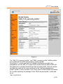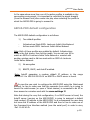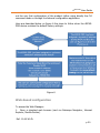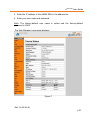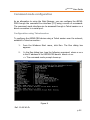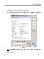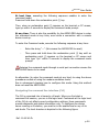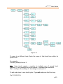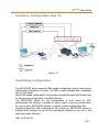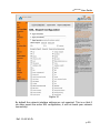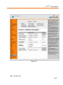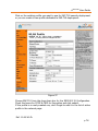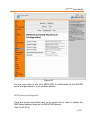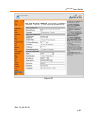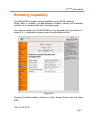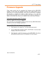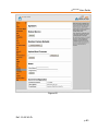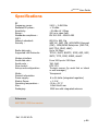
1
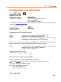
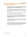
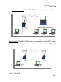
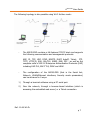
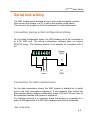
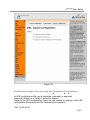
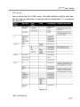
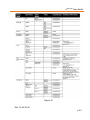
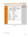
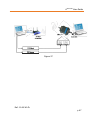
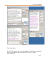
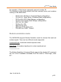
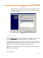
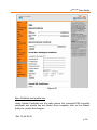
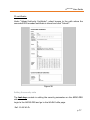
Wi-Fi b/g Modem
User Guide
No part of this document may be reproduced or transmitted (in electronic or
paper version, photocopy) without Adeunis RF consent.
This document is subject to change without notice.
All trademarks mentioned in this guide are the property of their respective
owner.
ADEUNIS RF
283, rue Louis Néel
38920 Crolles
France
Phone
Fax
+33 (0)4 76 92 07 77
+33 (0)4 76 08 97 46
Ref. 09-03-V0-jcs
ARF45-PRO User Guide
Table of contents
About this document ...................................................3
Declaration of conformity ...........................................4
Feature’s Overview .....................................................5
Power supply ...............................................................8
Serial link wiring .........................................................9
Connection during serial configuration phase ........................... 9
Connection for data transmission ............................................. 9
ARF45-PRO Configuration .........................................10
ARF45-PRO WLAN PROFILES .................................................11
ARF45-PRO default configuration ............................................19
Web-based configuration .......................................................20
Command mode configuration ................................................22
Configuration using Telnet session ................................................ 22
Configuration using a Serial Port connection .................................. 23
Navigating the command line interface (CLI) .................................. 24
Summary: Configuration How-To ............................................27
Duplicating configuration .......................................................27
Duplicating
Duplicating
Duplicating
Duplicating
XML group
configuration through the Web-based interface ............ 28
configuration through the Command Line Interface ....... 30
configuration through an FTP connection ..................... 31
configuration with Adeunis-RF configuration application 31
................................................................................... 32
Network Communication mode ................................43
Connect mode .......................................................................43
Accept mode .........................................................................45
Ref. 11-06-V0-ffr
p1
ARF45-PRO User Guide
Port numbers ........................................................................48
Modem emulation mode ........................................................49
Entering Command mode on the ARF45-PRO ..........................51
Security modes in details ..........................................53
Features overview .................................................................53
EAP methods supported .........................................................54
Security mode deployment .....................................................54
RADIUS authentication server: configuration ...........................55
Wireless Access Point: configuration .......................................63
EAP-TLS based deployment ...................................................64
PEAP based deployment ........................................................79
Roaming capability ...................................................82
COM port redirector ..................................................83
Firmware Upgrade ....................................................84
Specifications ............................................................86
Ref. 11-06-V0-ffr
p2
ARF45-PRO User Guide
About this document
This guide describes the ARF45-PRO devices, their options and accessories.
Ref. 11-06-V0-ffr
p3
ARF45-PRO User Guide
Declaration of conformity
Manufacturer’s name:
Manufacturer’s address
ADEUNIS R.F.
Parc Technologique PRE ROUX IV
283 rue Louis NEEL
38920 CROLLES - FRANCE
declares that the product if used and installed according to the user guide available on
our web site www.adeunis-rf.com
Product Name:
Product Number(s):
Product options:
ARF45
ARF7532A
Complies with the RTTE Directive 99/5/EC:
EMC:
Safety:
Radio:
conformity to the harmonized standard EN 301 489
conformity to the standard EN 60950-1/2001
conformity to harmonized standard EN 300-328 covering
essential radio requirements of the RTTE directive.
Exposure to radio frequency signals: Regarding the 1999/519/EC recommendation,
when using the device, keep the product at least 3 cm from your body.
Notes:
- Conformity has been evaluated according to the procedure
described in Annex III of the RTTE directive.
- Receiver class (if applicable): 3.
Crolles, November 12th, 2008
VINCENT Hervé / Quality manager
Download of the user guide
Thank you for having chosen the ADEUNIS RF products.
User guides can be uploaded directly on our web site www.adeunis-rf.com
Index
Products
Paragraph Modems > WIFI modem
Print version available upon request
9
Tel : +33 4 76 92 07 77
9
Email : [email protected]
Ref. 11-06-V0-ffr
p4
ARF45-PRO User Guide
Feature’s Overview
-
ARF45-PRO is a device that adds secure wireless 802.11 b/g (Wi-Fi)
networking capability to any device with a serial interface. Basically
the ARF45-PRO can be seen as a RS232/WIFI gateway.
-
The ARF45-PRO enables remote access to a serial port over a
wireless network. The data from the serial link is encapsulated into
TCP or UDP packets which can travel through any IP based
wireless network.
By the same token, the ARF45-PRO converts TCP or UDP packets
from any IP based wireless network onto serial data.
-
From a functional point of view, the major difference between the
ARF42/45 and the ARF45-PRO is the addition of the WPA2/802.11i
enterprise-grade security and authentication protocols (based on
the EAP/802.1X framework).
-
The ARF45-PRO’s integrated web server transforms a standalone
device into a networked product that can be managed remotely via
a standard web browser.
-
The ARF45-PRO operates as a WI-FI station and can thus be part
of an Infrastructure network (communication with other WI-FI
station through an Access Point) or an Ad-hoc network (direct Point
to Point communication with another WI-FI station).
Ref. 11-06-V0-ffr
p5
ARF45-PRO User Guide
Infrastructure mode: The ARF45-PRO is connected to an Access Point
Ad-hoc mode: The ARF45-PRO is directly connected to another WI-FI station.
In this mode, point to point communication between two ARF45-PRO
modems is also possible.
Ref. 11-06-V0-ffr
p6
ARF45-PRO User Guide
The following topology is also possible using Wi-Fi Ad-hoc mode:
-
The ARF45-PRO contains a full-featured TCP/IP stack and supports
the following communication and management protocols:
ARP, IP, TCP, UDP, ICMP, BOOTP, DHCP AutoIP, Telnet, FTP,
TFTP, HTTP(S), SSH, SSL/TLS, SNMP, DNS, PPP , as well as the
complete suite of 802.1X Enterprise Authentication Protocols (EAP)
including EAP-TLS, EAP-TTLS, PEAP and LEAP.
-
The configuration of the ARF45-PRO (that is the Serial link,
Network, WLAN/Ethernet interfaces, Security mode…parameters)
can be achieved in 2 ways:
1)
Through a terminal software using a PC serial port.
2)
Over the network, through a browser-based interface (which is
accessing the embedded web server) or a Telnet connection.
Ref. 11-06-V0-ffr
p7
ARF45-PRO User Guide
Power supply
To perform wiring of these products, the bottom part of the housing (part
with stuffing box) has to be opened by unscrewing the two stainless steel
screws on each side.
Retirer
les visthese
de la partie
Remove
screws
avec presse étoupe
The ARF45PRO product must be supplied from a DC voltage source. This
voltage source must be 8V minimum and must not exceed 36 VDC.
+
-
RTS RX
TX CTS
WLAN
ACT
+ DC Supply
Ref. 11-06-V0-ffr
p8
ARF45-PRO User Guide
Serial link wiring
The WIFI modem serial interface wiring is a two-step connection process:
First connect the modem to a PC to set up the modem configuration,
Then connect the modem to the final equipment for data transmission.
Connection during serial configuration phase
For the initial configuration phase, the WIFI modem has to be connected on
to a PC COM port. The set-up configuration software does not require
RTS/CTS wiring. The following scheme is an example of connection with a
PC:
Modem
(DCE)
+
-
RTS RX
TX CTS
WLAN
ACT
5 2 3
SUB-D 9
PC
(DTE)
Connection for data transmission
For the data transmission phase, the WIFI modem is attached by its serial
port to the final transmission equipment. If the hardware flow control has
been selected during modem configuration phase, RTS and CTS lines have to
be connected between both pieces of equipment.
The following scheme is an example where the modem is connected as a
piece of DCE equipment to a DTE with hardware flow control handshake:
Ref. 11-06-V0-ffr
p9
ARF45-PRO User Guide
Modem
(DCE)
+
-
RTS RX
TX CTS
WLAN
ACT
5
7 2
SUB-D 9
3 8
PC
(DTE)
ARF45-PRO Configuration
The ARF45-PRO comes with a default configuration.
The configuration is then modifiable through access to a set of parameters
that are detailed further below.
In order to fit the application, the ARF45-PRO’s configuration parameters can
easily be modified using two different methods.
Here are listed below the two methods for configuring the ARF45-PRO:
-
Through a web browser (by making a network connection to the
embedded web server, also called the Web Manager, of the
ARF45-PRO): the advantage of this method is that it offers a userfriendly graphical interface.
However this method requires the user to know what the WLAN
interface settings (Network, Basic and Security settings) of the
ARF45-PRO are. Indeed in order to make a network connection to
the ARF45-PRO, the user needs to configure an Access Point (or a
Wireless network card) with the same WLAN settings as the ones
contained in the ARF45-PRO.
Ref. 11-06-V0-ffr
p 10
ARF45-PRO User Guide
-
Through the Command Line Interface (accessible either over
the network by making a Telnet connection or locally by connecting
a terminal to the ARF45-PRO’s serial port): the advantage of this
method is that the user can access the ARF45-PRO configuration
without having the knowledge of its WLAN settings (for instance in
order to perform the very first configuration of the product which
contains the factory settings). However the drawback of this
method is that the command line interface is not user friendly and
thus requires the user to navigate through the parameters
structure tree and handle commands (it is actually a Cisco –like
CLI). However this burden can be avoided by using the Adeunis
configuration application which is a user-friendly application tool
enabling the configuration of the ARF45-PRO from the serial
interface. The purpose of this application is also to assist the user
in configuring the ARF45-PRO by providing him with a step by step
procedure.
Please refer to the “ARF45-PRO_CommandSet.html” file which
presents the parameters structure tree as well as all the available
commands and their definition.
The configuration parameters are organised in several groups, based on their
function: for instance the parameters pertaining to the network settings are
put together into a group of parameters named Network.
ARF45-PRO WLAN PROFILES
The ARF45-PRO may have up to four WLAN profiles active at the same time.
A profile corresponds to the configuration of a WLAN link on the ARF45-PRO.
In other words, a profile defines the parameters for the connection between
an ARF45-PRO and the wireless network.
Those parameters are of 3 types:
Ref. 11-06-V0-ffr
p 11
ARF45-PRO User Guide
-
Basic parameters: Network name (also called SSID), network
Topology and frequency channel (applicable only in Ad-hoc
topology).
-
Advanced parameters: TX data rate, TX power settings.
-
Security parameters: Parameters pertaining to the encryption and
authentication methods.
When using the web-based interface method for configuring the ARF45-PRO,
the WLAN profiles are listed in order of precedence under the page
Network-> Network 2-> Link-> Configuration (see figure 1 below):
Note: The ARF45-PRO can support 2 network interfaces: one 802.11 b/g
wireless network interface (which corresponds to “Network 2”) and one
Ethernet network interface (which corresponds to “Network 1”).
However, as of now, the Ethernet network interface is not available
on the product!
Ref. 11-06-V0-ffr
p 12
ARF45-PRO User Guide
Figure 1
By default, the ARF45-PRO product comes with two default profiles: one
which enables the connection to an Infrastucture Network (profile name is:
default_infrastructure_profile) and another one which enables the connection
to an Ad-Hoc network (profile name is: default_adhoc_profile).
Both of these profiles are set up with default network names (respectively
Lantronix Initial Infra Network and Lantronix Initial Adhoc Network) and no
security level activated.
The benefit from having these two default profiles activated is that by default
(which means when the product contains the factory settings) the ARF45Ref. 11-06-V0-ffr
p 13
ARF45-PRO User Guide
PRO can be configured over the network through an AP (Infrastructure) or a
Wireless Network Card (Ad-Hoc). The prerequisite for this is to apply the
ARF45-PRO’s default WLAN settings to the AP or the Wireless Card. On top of
this, a DHCP server must be present in the network in order to be able to
proceed to the very first configuration of the product over the network!!
The ARF45-PRO also gives the possibility to create new WLAN profiles.
For instance, the figures below (figure 2 to figure 5) show the four active
WLAN profiles contained in an ARF45-PRO device: the two default profile
(which have been kept) and two WLAN profiles which have been created for
different purpose.
Important Point:
The ARF45-PRO can be used to connect to another ARF45-PRO in Ad-Hoc
mode (for instance in order to establish a direct network connection between
2 ARF45-PRO).
If such a topology is to be used, the user must make sure that the AdHoc
merging setting is enabled (if not, trouble during the connection may
occur)!!!
Ref. 11-06-V0-ffr
p 14
ARF45-PRO User Guide
Figure 2
Ref. 11-06-V0-ffr
p 15
ARF45-PRO User Guide
Figure 3
Ref. 11-06-V0-ffr
p 16
ARF45-PRO User Guide
Figure 4
Ref. 11-06-V0-ffr
p 17
ARF45-PRO User Guide
Figure 5
The “EAP_TLS_secured_profile” and “PEAP_secured_profile” WLAN profiles
are profiles with the EAP authentication mode enabled.
From figure 1, we can see that the “default infrastructure profile” has
precedence over the EAP_TLS profile which means that the ARF45-PRO will
first search for a wireless Access Point with the same SSID, Channel number
and Security mode as the ones contained in the “default infrastructure
profile” profile. If such a profile is not found, then the ARF45-PRO will search
for a profile matching the settings of the “PEAP secured profile” profile and
so on.
Ref. 11-06-V0-ffr
p 18
ARF45-PRO User Guide
In the case where more than one of the active profiles is available in the
surrounding environment, it is important to note that the signal strength
(from the Access Point) also comes into play when selecting the profile to
which the ARF45-PRO is going to connect to.
ARF45-PRO default configuration
The ARF45-PRO default configuration is as follows:
1)
Two default profiles:
-
Infrastructure Mode SSID: Lantronix Initial Infra Network
Ad hoc mode SSID: Lantronix Initial Adhoc Network
Note: Both of these profiles are enabled by default. Infrastructure
Mode is the first choice, then Ad-Hoc mode. You can set your AP to
match an SSID of Lantronix Initial Infra Network or connect with
another wireless card in Ad-hoc mode with an SSID of Lantronix
Initial Adhoc Network.
2)
No encryption
3)
BOOTP, DHCP, and AutoIP enabled.
Note: AutoIP generates a random default IP address in the range
169.254.0.1 to 169.254.255.254 if no BOOTP or DHCP server is found.
In case the user wish to configure the ARF45-PRO using the Web-based
method, he has to make sure that the computer from which he is going to
launch the web-browser (or open a Telnet session) is connected to an AP or
have access to a wireless card with the same settings !!!
Note that during the very first configuration, if no DHCP server is found, the
AutoIP server (running on the ARF45-PRO) is going to assigned a default
(and random) IP address to the ARF45-PRO. As a consequence the user does
not know the IP address of the ARF45-PRO and thus he has to make use of
the Command Line Interface method (over the serial port!) in order to carry
Ref. 11-06-V0-ffr
p 19
ARF45-PRO User Guide
out the very first configuration of the product (either using directly the CLI
command mode or through the Adeunis configuration application.
Here are described below on figure 6 the steps to follow when the ARF45PRO device contains the default factory settings:
Figure 6
Web-based configuration
To access the Web Manager:
1. Open a standard web browser (such as Netscape Navigator, Internet
Explorer, Mozilla Firefox).
Ref. 11-06-V0-ffr
p 20
ARF45-PRO User Guide
2. Enter the IP address of the ARF45-PRO in the address bar.
3. Enter your user name and password.
Note: The factory-default user name is admin and the factory-default
password is PASS.
The Web Manager home page displays:
Figure 7
Ref. 11-06-V0-ffr
p 21
ARF45-PRO User Guide
Command mode configuration
As an alternative to using the Web Manager, you can configure the ARF45PRO through the command line interface (CLI) using a series of commands.
The command mode interface can be accessed through a Telnet session or a
direct connection to a serial port.
Configuration using Telnet session
To configure the ARF45-PRO device using a Telnet session over the network,
establish a Telnet connection:
1.
From the Windows Start menu, click Run. The Run dialog box
appears.
2.
In the Run dialog box, type the following command, where x.x.x.x
is the IP address of the ARF45-PRO device: telnet x.x.x.x
=> The command mode prompt shows up.
Figure 8
Ref. 11-06-V0-ffr
p 22
ARF45-PRO User Guide
Configuration using a Serial Port connection
To configure the ARF45-PRO device locally using a serial port, connect a
terminal or a PC running a terminal-emulation program to the device’s serial
port.
Figure 9
Note: Configure the terminal for 9600 baud, 8-bit, no parity, 1 stop bit, and
no flow control.
Ref. 11-06-V0-ffr
p 23
ARF45-PRO User Guide
At boot time, executing the following sequence enables to enter the
command mode:
Press and hold down the exclamation point (!) key.
Then, when an exclamation point (!) appears on the terminal or PC screen,
type xyz within 5 seconds to display the command mode prompt.
At any time: There is also the possibility for the ARF45-PRO device to enter
the command mode at any time, even while a connection with a remote
device is set up.
To enter the Command mode, execute the following sequence at any time:
-
Enter the string “---” (this causes the ARF45-PRO to reset).
-
Then press and hold down the exclamation point (!) key until an
exclamation point (!) appears on the terminal or PC screen and
then type “xyz” within 5 seconds to display the command mode
prompt.
Entering the command mode through a serial port connection causes the
ARF45-PRO device to be reset!
An alternative (to enter the command mode at any time) to using the above
procedure consists of using the modem emulation mode.
See in subsequent chapters how to configure this mode. Using this method
does not reset the ARF45-PRO.
Navigating the command line interface (CLI)
The CLI is organized into a hierarchy of levels. When you first start a
command line session, you are in the login level. Commands at the login level
of the CLI do not affect current configuration settings; these commands
provide diagnostic and status information only. To configure the device
server running on Evolution, you must be in the enable level or any of its
sub-levels. The level structure is depicted in the following figure:
Ref. 11-06-V0-ffr
p 24
ARF45-PRO User Guide
Figure 10
To move to a different level: Enter the name of that level from within its
parent level.
For example:
>enable (enable)#tunnel 2
Note: Some levels require a number to indicate one of several level
instances. In the example above the number 2 indicates that we would
like to configure the settings for tunneling on serial port 2.
To exit and return to one level higher: Type exit and press the Enter key.
Ref. 11-06-V0-ffr
p 25
ARF45-PRO User Guide
Note: Typing exit at the login level or the enable level will close the CLI
session.
To view the current configuration at any level: Type show. The configuration
for that level displays.
To view the list of commands available at the current level: At the command
prompt, type the question mark “?”. The list of current commands displays.
(There is no need to press Enter.)
Note: Items within < > (e.g. <string>) are required parameters.
To view the available commands and their explanations: At the command
prompt, type * and press Enter. The list of commands for that level and their
description displays.
To view the list of commands available for a partial command: At the
command prompt, type the partial command followed by the question mark
“?”. The list of current commands displays. (There is no need to press Enter.)
For example: <tunnel-1>#accept? displays a list of all accept commands at
the tunnel level.
To view the available commands and their explanations for a partial
command: At the command prompt, type the partial command followed by *
and press Enter. The list of partial commands and descriptions displays.
For example: <tunnel-1>#accept* displays a list of all accept commands and
descriptions at the tunnel level.
Ref. 11-06-V0-ffr
p 26
ARF45-PRO User Guide
Summary: Configuration How-To
Figure 11
Duplicating configuration
The ARF45-PRO device supports XML-based configuration which make device
configuration transparent to users. The XML is easily editable with a standard
text or XML editor.
Using XML-based configuration file provide a straightforward and flexible way
to manage the configuration of multiple devices.
The ARF45-PRO allows for the configuration of units using an XML
configuration file making it possible to easily export a current configuration
for use on other ARF45-PRO devices or import a saved configuration file.
Exporting/Importing XML configuration file from/to an ARF45-PRO device is
possible both through the use of the web-based interface or the use of the
command mode interface.
Ref. 11-06-V0-ffr
p 27
ARF45-PRO User Guide
When exporting the current system configuration in XML format, the
generated XML file can be imported later to restore a configuration. It can
also be modified and imported to update the configuration on this ARF45PRO device or another ARF45-PRO device. The XML data can be exported to
the browser window or to a file on the file system.
Duplicating configuration through the Web-based interface
The Web interface can be used to import (figure 13) and export (figure 12)
an XML configuration file to the ARF45-PRO file system. It can also be used
to import an XML configuration file from an external source such as your local
hard drive.
Ref. 11-06-V0-ffr
p 28
ARF45-PRO User Guide
Figure 12
By default the network interface settings are not exported. This is so that if
you later export the entire XML configuration, it will not break your network
connectivity.
Ref. 11-06-V0-ffr
p 29
ARF45-PRO User Guide
Figure 13
Duplicating configuration through the Command Line Interface
An XML configuration file can be imported (captured) or exported
(dumped) directly to a Telnet or serial line session.
Capturing an XML configuration record can be started by pasting a valid XML
configuration file directly into the Command line interface.
Ref. 11-06-V0-ffr
p 30
ARF45-PRO User Guide
To dump the current configuration, use the following command:
xcr dump <param>
By default param is empty and the whole configuration is dumped and
displayed on the terminal window.
The user may choose to export only part of the configuration by setting
param to the group’s names that have to be exported:
Example:
xcr dump interface:2,arp,ppp will export and display the content of the arp
group, the content of the ppp group and and the content oif the instance 2 of
the interface group.
Duplicating configuration through an FTP connection
An XML configuration file can be exported or imported to or from the PC’s
filesystem by setting up a connection to the FTP server of the ARF45-PRO.
By default the FTP server is running and the default username/pwd is:
admin/none.
Export: type the command: get matchport_bg_pro.xcr onto the FTP client
window. As a result, the current configuration of the ARF45-PRO is exported
onto a file named matchport_bg_pro.xcr created in the FTP directory, which
is the directory from which you ftp’ed.
Import: type the command: put matchport_bg_pro.xcr onto the FTP client
window. As a result, the content of the matchport_bg_pro.xcr configuration
file (that should be located in the FTP directory, which is the directory from
which you ftp’ed) is loaded in the ARF45-PRO.
For this to take effect, the ARF45-PRO must be rebooted!
Duplicating configuration with Adeunis-RF configuration application
Using the Adeunis-RF application enables the user to export and import
configuration over the serial port.
Ref. 11-06-V0-ffr
p 31
ARF45-PRO User Guide
XML group
Here is below the list of XML group. This table indicates whether each item
can be imported, exported, or exported with the placeholder “<!--configured
and ignored-->”:
Figure 14
Ref. 11-06-V0-ffr
p 32
ARF45-PRO User Guide
Figure 15
Ref. 11-06-V0-ffr
p 33
ARF45-PRO User Guide
Figure 16
Ref. 11-06-V0-ffr
p 34
ARF45-PRO User Guide
Figure 17
Ref. 11-06-V0-ffr
p 35
ARF45-PRO User Guide
Figure 18
Ref. 11-06-V0-ffr
p 36
ARF45-PRO User Guide
Figure 19
Ref. 11-06-V0-ffr
p 37
ARF45-PRO User Guide
Figure 20
Ref. 11-06-V0-ffr
p 38
ARF45-PRO User Guide
Figure 21
Ref. 11-06-V0-ffr
p 39
ARF45-PRO User Guide
Figure 22
Ref. 11-06-V0-ffr
p 40
ARF45-PRO User Guide
Figure 23
Ref. 11-06-V0-ffr
p 41
ARF45-PRO User Guide
Figure 24
Ref. 11-06-V0-ffr
p 42
ARF45-PRO User Guide
Network Communication mode
A serial tunneling communication is a communication between two serial
devices connected over an IP-based network.
Two ARF45-PRO modem devices can be used to create a “serial tunnel” over
an IP network (it does not matter whether the connection is a point to point
connection, in the case of ad-hoc network, or a connection via an AP, in case
of infrastructure network). This can be thought of as cable replacement.
The ARF45-PRO supports two tunneling connections simultaneously on its
serial port. One of these connections is Connect Mode and the other
connection is Accept Mode.
When any character comes in through the serial port, it gets copied to both
the Connect Mode connection and the Accept Mode connection (if both are
active). See the figures on the next pages.
Connect mode
In this mode, the ARF45-PRO actively makes a connection. In other words,
the ARF45-PRO behaves like an IP client. The receiving node on the network
must listen for the Connect Mode’s connection.
Note: Connect Mode is disabled by default!
For Connect Mode to function, it must be enabled, have a remote station
(node) configured, and a remote port configured (TCP or UDP).
Enter the remote station as an IP address or DNS name. The ARF45-PRO will
not make a connection unless it can resolve the address.
Ref. 11-06-V0-ffr
p 43
ARF45-PRO User Guide
Figure 25
Connect Mode supports the following protocols:
-
TCP
AES encryption over UDP
AES encryption over TCP
SSH (the ARF45-PRO is the SSH client)
UDP (available only in Connect Mode because it is a connectionless
protocol).
Ref. 11-06-V0-ffr
p 44
ARF45-PRO User Guide
Connect Mode has five states:
-
Disabled (no connection)
Enabled (always makes a connection)
Active if it sees any character from the serial port
Active if it sees a specific (configurable) character from the serial
port.
Modem emulation
Accept mode
In this mode, the ARF45-PRO listens for a connection. In other words, the
ARF45-PRO behaves like an IP server. A node on the network initiates the
connection.
Note: Accept Mode is enabled by default!
In Accept Mode, the ARF45-PRO waits for a connection. The configurable
local port is the port the remote device connects to for this connection. There
is no remote port or address. The default local port is 10001.
Ref. 11-06-V0-ffr
p 45
ARF45-PRO User Guide
Figure 26
Ref. 11-06-V0-ffr
p 46
ARF45-PRO User Guide
Figure 27
Ref. 11-06-V0-ffr
p 47
ARF45-PRO User Guide
Figure 28
Port numbers
Every TCP connection and every UDP datagram is defined by a destination
and source IP address, and a destination and source port number.
Ref. 11-06-V0-ffr
p 48
ARF45-PRO User Guide
For example, a Telnet server commonly uses port number 23.
The following is a list of the default (and thus reserved) server port numbers
running on the ARF45-PRO:
-
TCP Port 22: SSH Server (Command Mode configuration)
TCP Port 23: Telnet Server (Command Mode configuration)
TCP Port 80: HTTP (Web Manager configuration)
TCP Port 443: HTTPS (Web Manager configuration)
UDP Port 161: SNMP
TCP Port 21: FTP
UDP Port 69: TFTP
UDP Port 30718: Query port
TCP/UDP Port 10001: Tunnel 1
Modem emulation mode
The ARF45-PRO supports Modem Emulation mode for devices that send out
modem signals. There are two different modes supported:
Command Mode: sends back verbal response codes.
Data Mode: information transferred in is also transferred out.
Command mode
The Modem Emulation’s Command Mode supports the standard AT command
set. For a list of available commands from the serial or Telnet login, enter
AT?
Ref. 11-06-V0-ffr
p 49
ARF45-PRO User Guide
Figure 29
Ref. 11-06-V0-ffr
p 50
ARF45-PRO User Guide
All of these commands behave like a modem. For commands that are valid
but not applicable to the ARF45-PRO, an “OK” message is sent (but the
command is silently ignored).
The ARF45-PRO attempts to make a Command Mode connection as per the
IP/DNS/port numbers defined in Connect Mode. It is possible to override the
remote address, as well as the remote port number.
When using ATD, enter 0.0.0.0 to switch to Command Mode.
Entering Command mode on the ARF45-PRO
Like mentioned previously in this document, the modem emulation mode can
be used to enter the command mode at any time. In order for this to work,
both the Accept and Connect mode has to be set with the Modem emulation
mode. Then entering the “+++” string enables to switch to command mode
at any time without resetting the device.
For the Accept tunnel connection, the connection can be established
automatically (initiated from a remote node on the network) if configured.
However for the Connect tunnel connection, the ATD command has to be
entered in order to establish the connection with the remote node on the
network.
Ref. 11-06-V0-ffr
p 51
ARF45-PRO User Guide
Figure 30
Ref. 11-06-V0-ffr
p 52
ARF45-PRO User Guide
Security modes in details
Features overview
The ARF45-PRO device enables to add Wi-Fi networking capability to devices
with the highest WPA2/802.11i enterprise-grade security and authentication
protocols.
Like the ARF45, the ARF45-PRO supports the WPA/WPA2 Personal mode
which is a security mode that uses pre-shared key (PSK) for authentication.
On top of that, the ARF45-PRO also supports the WPA/WPA2 Enterprise
mode which enables to meet the rigorous requirement of enterprise security
by leveraging the 802.1X authentication framework which in turns relies on
EAP and an authentication server (RADIUS server) to provide strong mutual
authentication between the client and the authentication server via an access
point.
The picture below depicts the deployment scheme in which are involved
three components: the WIFI client (for instance an ARF45-PRO) also called
the supplicant, the Access Point also called the authenticator and the
authentication RADIUS server in charge of performing the client
authentication.
Figure 31
Ref. 11-06-V0-ffr
p 53
ARF45-PRO User Guide
Note: WPA and WPA2/IEEE 802.11i are not available for Ad-hoc topology.
EAP methods supported
Here are the EAP methods that are supported by the ARF45-PRO:
LEAP = Lightweight Extensible Authentication Protocol.
EAP-TLS = Extensible Authentication Protocol - Transport Layer Security:
requires authentication certificates on both the network side and the ARF45PRO side.
EAP-TTLS = Extensible Authentication Protocol - Tunneled Transport Layer
Security.
PEAP = Protected Extensible Authentication Protocol.
EAP-TTLS and PEAP have been developed to avoid the requirement of
certificates on the client side which makes deployment more cumbersome.
Both make use of EAP-TLS to authenticate the server (network) side and
establish an encrypted tunnel. This is called the outer-authentication.
Then a conventional authentication method (MD5, MSCHAP, etc.) is used
through the tunnel to authenticate the ARF45-PRO. This is called innerauthentication.
Security mode deployment
This chapter describes how to deploy the WPA/WPA2 Enterprise security
mode using the PEAP and EAP-TLS authentication methods.
The deployment has been carried out using a Windows Server 2003
authentication server running Authentication services, a Certificate Authority
and a RADIUS server.
When using EAP-TLS, EAP-TTLS or PEAP authentication methods at least
one authority certificate will have to be installed on the ARF45-PRO that is
Ref. 11-06-V0-ffr
p 54
ARF45-PRO User Guide
able
to
verify
the
Radius
server’s
certificate.
In case of EAP-TLS also a certificate and matching private key need to be
configured to authenticate the ARF45-PRO to the Radius server (that is to
identify itself ) and sign its messages.
Prior to embark on the configuration of the ARF45-PRO, both EAP-TLS and
PEAP based authentication methods require the RADIUS server and the
access point (which is also called the RADIUS client) to be correctly
configured.
RADIUS authentication server: configuration
Add users to the domain:
-
In the Active Directory Users and Computers console tree,
right-click Users, click New, and then click User.
-
In the New Object – User dialog box, type WirelessUser in First
name and type WirelessUser in User logon name. This is shown in
the following figure.
Ref. 11-06-V0-ffr
p 55
ARF45-PRO User Guide
Figure 32
-
Click Next. In the New Object – User dialog box, type a password
of your choice in Password and Confirm password. Clear the User
must change password at next logon check box, and then click
Next. This is shown in the following figure.
Ref. 11-06-V0-ffr
p 56
ARF45-PRO User Guide
Figure 33
-
In the final New Object – User dialog box, click Finish.
Allow wireless access to users:
-
In the Active Directory Users and Computers console tree, click the
Users folder, right-click WirelessUser, click Properties, and then
click the Dial-in tab.
-
Select Allow access, and then click OK.
Add groups to the domain:
-
In the Active Directory Users and Computers console tree, rightclick Users, click New, and then click Group.
-
In the New Object – Group dialog box, type WirelessUsers in Group
name, and then click OK. This is shown in the following figure.
Ref. 11-06-V0-ffr
p 57
ARF45-PRO User Guide
Figure 34
Add users to the WirelessUsers group :
-
In the details pane of the Active Directory Users and Computers,
double-click WirelessUsers.
-
Click the Members tab, and then click Add.
-
In the Select Users, Contacts, Computers, or Groups dialog box,
type wirelessuser in Enter the object names to select.
-
Click OK. In the Multiple Names Found dialog box, click OK. The
WirelessUser user account is added to the WirelessUsers group.
-
Click OK to save changes to the WirelessUsers group.
Add a Wireless AP as RADIUS client :
Ref. 11-06-V0-ffr
p 58
ARF45-PRO User Guide
-
In the console tree of the Internet Authentication Service snap-in,
right-click RADIUS Clients, and then click New RADIUS Client.
-
On the Name and Address page of the New RADIUS Client wizard,
in Friendly name, type WirelessAP. In Client address (IP or DNS),
type the IP address of the AP on the network, and then click Next.
This is shown in the following figure.
Figure 35
-
Click Next. On the Additional Information page of the New RADIUS
Client wizard, for Shared secret, type a RADIUS shared secret for
the wireless AP, and then type it again in Confirm shared secret.
This is shown in the following figure. The shared secret entered
here needs to match the RADIUS shared secret on the
configuration of the wireless AP.
Ref. 11-06-V0-ffr
p 59
ARF45-PRO User Guide
Figure 36
-
Click Finish.
Create and configure remote access policy :
-
In the console tree of the Internet Authentication Service snap-in,
right-click Remote Access Policies, and then click New Remote
Access Policy.
-
On the Welcome to the New Remote Access Policy Wizard page,
click Next.
-
On the Policy Configuration Method page, type Wireless access to
intranet in Policy name. This is shown in the following figure.
Ref. 11-06-V0-ffr
p 60
ARF45-PRO User Guide
Figure 37
-
Click Next. On the Access Method page, select Wireless. This is
shown in the following figure.
Figure 38
-
Click Next. On the User or Group Access page, select Group. This is
shown in the following figure.
Ref. 11-06-V0-ffr
p 61
ARF45-PRO User Guide
Figure 39
-
Click Add. In the Select Groups dialog box, click Locations, select
example.com, and then click OK.
-
Type wirelessusers in the Enter the object names to select box.
This is shown in the following figure.
Figure 40
-
Click OK. The WirelessUsers group in the example.com domain is
added to the list of groups on the User or Group Access page. This
is shown in the following figure.
Ref. 11-06-V0-ffr
p 62
ARF45-PRO User Guide
Figure 41
-
Click Next. On the Authentication Methods page, select “Smart card
or other certificate” (for EAP-TLS deployment) or “Protected EAP”
(for PEAP deployment). In case of PEAP deployment, the user also
has to choose the inner-authentication method (MS-CHAP v2,
CHAP …) to be used.
-
Click Next. On the Completing the New Remote Access Policy page,
click Finish.
Wireless Access Point: configuration
On the AP side there is only a few things to do:
-
In the advance security settings, select the WPA/WPA2 802.1X
authentication and security protocols.
-
Entering the IP address of the RADIUS server.
-
Entering the authentication port of the RADIUS server (1812 by
default).
Ref. 11-06-V0-ffr
p 63
ARF45-PRO User Guide
-
Entering the shared secret, which must match the shared secret
previously entered on the RADIUS server.
EAP-TLS based deployment
There are several steps that have to be carried out in order to deploy the
EAP-TLS based security mode on the ARF45-PRO device.
The EAP-TLS method requires authentication certificates on both the network
side (that is on the authentication RADIUS server) and the ARF45-PRO side.
Certificate generation
So the very first step (after having configured the RADIUS server and the
Access Point) consists of generating two certificates: the user/client
certificate (along with its private key) and the Certificate Authority (CA) root
certificate.
Here are described below the steps to follow in order to generate the client
certificate:
-
Make sure that Certificate Services are running on the Windows
server. Open the Services program though the Start Menu (Start>Administrative Tools->Services). Find the Certificate Services line
and check if the status shows up as “Started”. If not, right click on
the Certificate Services line and select Start.
Ref. 11-06-V0-ffr
p 64
ARF45-PRO User Guide
Figure 42
-
On the Windows server, open a web browser (e.g. Internet
Explorer), and enter http://127.0.0.1/certsrv for the address. If
prompted for user name and password, enter those configured for
the EAP authentication user.
Ref. 11-06-V0-ffr
p 65
ARF45-PRO User Guide
Figure 43
-
Click on “Request a certificate”. On the page that loads, click on
“advanced certificate request”.
Ref. 11-06-V0-ffr
p 66
ARF45-PRO User Guide
Figure 44
-
On the next page click on “Create and submit a request to this CA”.
Ref. 11-06-V0-ffr
p 67
ARF45-PRO User Guide
Figure 45
-
On the page that loads select “User” under Certificate Template.
Make sure “Mark keys as exportable” is selected, and also select
“Export keys to file”. Then select a full path name to save the
private key to under “Full path name:” The request format should
be set to CMC. Select a Friendly name in the box provided. Once
completed, click on the “Submit” button. If prompted whether or
not you want to request a certificate now, click “Yes”.
Ref. 11-06-V0-ffr
p 68
ARF45-PRO User Guide
Figure 46
-
When prompted to create a private key password, select “None”.
Figure 47
Ref. 11-06-V0-ffr
p 69
ARF45-PRO User Guide
-
On the next page, make sure that “DER encoded” is selected, and
click on “Download certificate”.
Figure 48
Here are described below the steps to follow in order to generate
the CA root certificate:
-
Open the Certificate Authority Program (assumes certificate
authority is already setup). You can find the CA in Start
Menu/Administrative Tools/Certificate Authority.
Ref. 11-06-V0-ffr
p 70
ARF45-PRO User Guide
Figure 49
-
Right click on the CA and select “Properties”. Then click on “View
Certificate”.
Ref. 11-06-V0-ffr
p 71
ARF45-PRO User Guide
Figure 50
-
Click on the Details tab, and then the “Copy to File” button.
Figure 51
Ref. 11-06-V0-ffr
p 72
ARF45-PRO User Guide
-
Click “Next” on the initial certificate export wizard window. Then
select “DER encoded binary X.509 (.CER)” and click the “Next”
button.
Figure 52
-
Select a file path to export to by clicking on the browse button,
name the file and click save. Then click “Next”.
Ref. 11-06-V0-ffr
p 73
ARF45-PRO User Guide
Figure 53
-
Now click Finish. You will see “The Export was successful.” Window
and click OK. Then click OK twice more to exit all windows and
close the CA program.
Figure 54
Certificate conversion
Then the second step consists in converting the certificates’s format onto a
format that is supported by the ARF45-PRO, that is the PEM format.
Certificates and private keys can be stored in several file formats. Best known
are PKCS12, DER and PEM. Certificate and key can be in the same file or in
separate files. The key can be encrypted with a password or not.
The ARF45-PRO currently only accepts separate PEM files and the key
needs to be unencrypted!!
Ref. 11-06-V0-ffr
p 74
ARF45-PRO User Guide
The user certificate as well as the CA certificate have been generated in the
DER format.
However the ARF45-PRO only supports for certificate in PEM format => thus
a conversion has to be performed in order for the certificates to be uploaded
onto the ARF45-PRO.
For this purpose two utility tools are required: openssl and pvktool.
Openssl enables to convert the certificate file from DER format onto PEM
format, whereas pvktool enables to convert the private key file from the PVK
format onto the PEM format.
Those tools as well as a procedure explaining how to carry out the
conversion can be downloaded from Adeunis web site.
Certificate upload
The third step consists in uploading the certificates onto the ARF45-PRO.
Login to the ARF45-PRO and go to the SSL page:
Ref. 11-06-V0-ffr
p 75
ARF45-PRO User Guide
Figure 55
User Certificate and private key:
Under Upload Certificate set the paths where the converted PEM encoded
certificate and private key are stored. Once complete, click on the Submit
button to commit the changes.
Ref. 11-06-V0-ffr
p 76
ARF45-PRO User Guide
CA certificate:
Under “Upload Authority Certificate”, select browse to the path where the
converted PEM encoded certificate is stored and click “Submit”.
Figure 56
Setting the security suite
The last step consists in setting the security parameters on the ARF45-PRO
side
Login to the ARF45-PRO and go to the WLAN Profile page.
Ref. 11-06-V0-ffr
p 77
ARF45-PRO User Guide
Click on the existing profile you want to use for EAT-TLS security deployment
or you can create a new profile dedicated to EAP-TLS deployment.
Figure 57
Choose EAP-TLS from the drop down box for the IEEE 802.1X Configuration.
Check the boxes for CCMP & TKIP for Encryption and click submit.
If the profile is a newly created one, don’t forget to add it in the list of active
profile in the network page:
Ref. 11-06-V0-ffr
p 78
ARF45-PRO User Guide
Figure 58
You are now ready to use your ARF45-PRO to authenticate to the RADIUS
server and get access to your wireless network.
PEAP based deployment
There are several steps that have to be carried out in order to deploy the
PEAP based security mode on the ARF45-PRO device.
Ref. 11-06-V0-ffr
p 79
ARF45-PRO User Guide
PEAP have been developed to avoid the requirement of certificates on the
client side which makes deployment more cumbersome.
So PEAP methods requires only one authority certificate to be installed on the
ARF45-PRO so to be able to verify the Radius server’s certificate.
All the steps (listed on the previous chapter) that apply to the EAP-TLS
method also apply to the PEAP method.
The only differences are:
-
The user does not need to generate a user/client certificate and
thus only the CA root certificate is uploaded in the ARF45-PRO (on
the SSL page).
-
On the WLAN Profile page choose PEAP from the drop down box
for the IEEE 802.1X Configuration.
Also, select the PEAP option (MS-CHAP v2, CHAP …) and check the
boxes for CCMP & TKIP for Encryption.
Enter the username and password that are used for identifying the
ARF45-PRO to the RADIUS server on the network.
Username and Password correspond to the username and
password entered when creating the user account on the
authentication RADIUS server.
Then click submit.
Ref. 11-06-V0-ffr
p 80
ARF45-PRO User Guide
Figure 59
Ref. 11-06-V0-ffr
p 81
ARF45-PRO User Guide
Roaming capability
The ARF45-PRO provides roaming capability across WLAN networks.
When WPA2 is enabled, pre-authentication enables smooth and automatic
transition to an access point with a stronger signal.
The roaming feature of the ARF45-PRO can be enabled from the Network->
Network 2-> configuration pages using the web-based method.
Figure 60
Checking Enabled enables roaming to other Access Points with the same
SSID.
Ref. 11-06-V0-ffr
p 82
ARF45-PRO User Guide
COM port redirector
A COM Port Redirector (CPR) is application software that enables COM Portbased applications to communicate over a network to remote equipment.
The main purpose is to enable the control of COM port-based equipment over
an IP-based network.
Com Port Redirector maps ‘virtual COM’ ports on a PC platform.
It redirects application data destined to an attached device via the PC’s local
serial (COM) port: Rather than going out the local port, the data is
transmitted across the IP-based wireless network using TCP/IP.
An ARF45-PRO attached to the wireless network receives the data and
transfers it from its own serial port to the attached equipment.
Conversely, data sent from the networked equipment to the serial port of an
ARF45-PRO is transmitted back to the application software on the PC via the
wireless IP-based network.
Com Port Redirector receives the data and presents it to the control
application as if it came from a COM port via a local serial connection.
Figure 61
Ref. 11-06-V0-ffr
p 83
ARF45-PRO User Guide
Firmware Upgrade
There exists several way for upgrading the firmware of the ARF45-PRO
modem. In every case, the firmware is written into a RAM memory (as a
zipped file) as it is being downloaded. Then once the download is completed
the firmware is unzipped and written to flash memory=> so in case the
download process does not run until completion (for instance: because of a
failure on the radio link), there are no impact at all on the current firmware.
From remote connection using FTP protocol:
Simply do a put of the firmware .romz file.
The .romz file is a compressed file which contains both the ARF45-PRO WLAN
firmware and the web manager application.
From the ARF45-PRO Web Manager’s File system page:
1.
Click System in the menu bar. The File system page opens.
2.
In the Upload New Firmware section, click Browse. A pop-up page
displays; locate the firmware file.
3.
Click Upload to install the firmware on the ARF45-PRO. The device
automatically reboots upon the installation of new firmware.
Ref. 11-06-V0-ffr
p 84
ARF45-PRO User Guide
Figure 62
Ref. 11-06-V0-ffr
p 85
ARF45-PRO User Guide
Specifications
RF
Frequency range :
Radiated RF power :
Sensitivity :
Range :
Standards compliance :
WIFI
Network standard :
Security :
Radio data rate :
Supported LAN Protocols :
Modem interface
Serial data rate :
Serial ports :
Flow control :
Set-up and configuration :
Mode :
General information
Power supply :
Electric Power
Operating temperature :
Size :
Packaging :
2.412 – 2.484 GHz
+ 15 dBm
- 91 dBm @ 1 Mbps
200 m in open field
EN 300-328 – EN301-489
802.11b; 802.11g
WEP 64, WEP 128, WPA/WPA2-Personal
(PSK), WPA/WPA2-Enterprise (EAP-TLS,
EAP-TTLS, PEAP, LEAP)
Up to 54 Mbps
TCP-IP, DHCP, BOOTP, ICMP, ARP, UDP,
SMTP, TFTP, ICMP, SNMP, AutoIP
From 300 bps to 250 Kbps
TxD, RxD.
RTS, CTS
Through menus (by serial link or telnet
or web manager)
Transparent
8 to 36 Volts (integrated regulator)
< 1,2 W
-30 to +70 °C
145x100x40 mm
IP65 box with integrated antenna
References
ARF7532I : IP65 box version
Ref. 11-06-V0-ffr
p 86