1
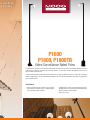
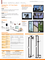
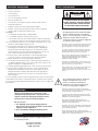
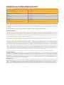
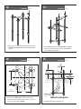
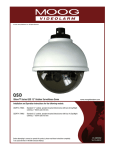
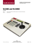
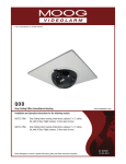
HALLGREN, RESTIFO, LOOP & COUGHLIN, ARCHITECTS
ADDENDUM NO. 2
January 9, 2014
DIGITAL CAMERA SYSTEM FOR IROQUOIS JR./SR. HIGH SCHOOL
4301 Main Street
Erie, Pennsylvania 16511
For
Iroquois School District
800 Tyndall Avenue
Erie, Pennsylvania 16511
NOTICE TO BIDDERS OF RECORD - This Addendum forms a part of the Contract Documents and modifies
the original project manual and drawings. Bidders shall carefully examine drawings and project manual for
revised and updated items.
NOTE - Bidder must acknowledge receipt of this addendum by inserting its number and date on their bid
form. Failure to do so may subject bidder for disqualification.
GENERAL NOTES AND SPECIFICATION
ITEM #1
FORM OF PROPOSAL – Please utilize the revised Form of Proposal included with this
addendum and submit in duplicate as noted in the specifications.
ITEM #2
NOTICE TO CONTRACTORS – Please note that any and/or all permits and fees are by the
General Contractor (Digital Camera System).
ITEM #3
PRE-BID NOTES
nd
1. Add two cameras in the library (2 floor) as shown on revised camera layouts. Add any necessary
licenses.
2. Cameras 57 – 58 and 62 – 65 to be removed from their respective light poles and installed as follows
a. Install two Videolarm P1600 poles, one on either side of the light pole previously supporting
cameras 62 – 65. Provide one Videolarm PV4 and PV8 for each pole. Poles to be mounted
as described in Videolarm installation instructions. No other holes shall be made into poles
as doing so would void the manufacture warranty (see attached catalog cut).
b. Install one Videolarm P1600 pole, to the side of the light pole previously supporting cameras
57 - 58. Provide one Videolarm PV4 and PV8. Pole to be mounted as described in
Videolarm installation instructions. No other holes shall be made into pole as doing so would
void the manufacture warranty (see attached catalog cut).
3. Add two cameras in the auditorium as shown on the revised camera layouts. Also provide a
deduction from the base price for these two cameras (Deduct Alternate #3). Cameras in the
auditorium shall have IR illuminators with a range no less than 30m. Add any necessary licenses.
Iroquois JR./SR. High School – Digital Camera System– 12/13
Iroquois School District
ADDENDUM #2 – Page 1
HALLGREN, RESTIFO, LOOP & COUGHLIN, ARCHITECTS
4. Add a PTZ camera to the press box of the stadium with the primary intent to see the baseball field to
the south and to be used during events for other purposes. The PTZ camera shall be the Axis
Q6035-E with corner mount or equal. Provide a deduct from the base quote for this camera (Deduct
Alternate #4). Add any necessary licenses.
5. Change the stadium press box network switch to a switch rated to -40C.
6. Cabling through pool basement and out to poles shall be direct burial type cable.
7. Cabling through gymnasium to be located as close to the roof deck as possible in the joist space. If it
is not, it must be in conduit.
Requests for Clarifications
1.
Are fixed focal length cameras acceptable for this project?
Answer: Fixed focal length cameras will only be considered for the interior cameras. Cameras are to be
mounted to minimize blind spots between cameras and unnecessary wall or ceiling segments, by adjusting
the final mount location with regard to the limitation of a fixed focal length. A minimum of 5 feet of extra cable
shall be coiled at the camera location to accommodate mounting adjustments as necessary. Where a camera
is shown to be mounted in a corner, the camera shall be mounted as close to the wall as possible to minimize
blind spots.
2.
With regards to 3.3.2.2.l.vii, “The player will have the option to allow an object search. The user will
be able to define an area and seek out changes in the image within that area.” Does a thumbnail search
meet the intent of this section.
Answer: No
3.
Is the only requirement with regards to Apple compatibility that the software can be accessed through
safari?
Answer: Yes, additionally systems with native iOS apps would be preferred.
4.
Are the alternates DEDUCTS, or alternate ADDS?
Answer: The base price is to include all cameras as shown. A deduct price shall be given for the alternates
listed on the proposal form.
5.
Can exterior mounted cameras be mounted directly to the building?
Answer: No, all exterior cameras shall be provided with a wall pendant mount.
6.
Is there a Manufacturer Model or type of Monitor being requested?
Answer: Provide a 23” monitor for the server as well as keyboard and mouse.
7.
Is there a recommended Manufacturer / Model for the Wireless Bridge transmitter & receiver?
Answer: There is no recommended Manufacture for the wireless bridge. The selected equipment must be
non-proprietary. The wireless bridge must be capable and licensed to allow for the anticipated bandwidth of
Iroquois JR./SR. High School – Digital Camera System– 12/13
Iroquois School District
ADDENDUM #2 – Page 2
HALLGREN, RESTIFO, LOOP & COUGHLIN, ARCHITECTS
the cameras being installed with 100% overhead for future expansion. If multiple streams from one camera
will be necessary for a given solution be sure to account for this additional bandwidth. The wireless
equipment shall be rigidly mounted to withstand adverse weather conditions.
8.
Will the school district supply all necessary switches?
Answer: No, the district is not supplying switches for the stadium or maintenance buildings. Additionally, if a
contractor decides to add additional switches to overcome wiring distance limitations these would not be
provided by the school district and must be provided by the contractor.
9.
Please clarify temperature rating requirements for the stadium equipment
Answer: Supply a switch rated for -40C. If the selected switch does not support PoE a separate power
supply UL listed for CCTV may be used to power the cameras.
10.
With regard to approved equals, will the auto-focus feature of the P3346-VE be a requirement to
meet this specification?
Answer: The auto-focus is not critical to this spec. As with any camera system installation all the cameras
must be aimed and focused (manually or automatic) according to the school districts requirements. Any
cameras that require refocusing during the warranty period will be refocused without charge to the school
district.
11.
What is the quantity of cameras for this bid?
Answer: The quantity and type of cameras can be found on the camera system layout as provided in this
addendum.
Additional Notes:
Provide all labor equipment and materials for all work indicated as necessary to provide a complete and
usable system. All items shown and specified are to be new and shall be provided by the security contractor
unless specifically stated otherwise
In cases where the term ‘provide’ is used throughout the contract documentation, it shall mean furnish, install
and service.
All work shall be installed in accordance with the latest editions of the following requirements: National
Electrical Code (NEC) (NFPA 70), the National Life Safety Code (NFPA 101), the Pennsylvania state building
code and all state and local ordinances that may supplement or supersede national codes.
The security contractor shall obtain and pay for all inspection and permitting fees as required by law.
The security contractor shall verify equipment characteristics and mounting requirements prior to device and
cable rough in and installation.
All penetrations of fire rated floor slabs, fire rated walls and fire rated enclosures shall be sleeved in
appropriately sized rigid steel conduit and firestopped in accordance with the National Electrical Code and all
application fire codes. Sleeving and fire stopping shall be provided by the individual penetrating said slab of
wall.
Where installed outdoors or in damp or humid environments, enclosures utilized to house security equipment,
used as pull boxes for security cabling or used to contain splices for security cabling shall be of a fiberglass
NEMA 4X rating or better.
Iroquois JR./SR. High School – Digital Camera System– 12/13
Iroquois School District
ADDENDUM #2 – Page 3
HALLGREN, RESTIFO, LOOP & COUGHLIN, ARCHITECTS
All low voltage cabling shall have jacketing appropriate for the environment in which it is installed. Direct
burial jacketing is required for installation in any underground or exterior mounted raceway or any damp or
wet environment.
All low voltage cabling where installed in an underground environment must be installed inside a raceway
suitable for the environment in which it is installed and at a depth in accordance with NEC table 300.5.
Please find attached four revised camera location drawings and a cut sheet for the poles to be
provided and installed by the successful contractor. Also attached are the required installation
instructions for the poles.
END OF ADDENDUM NO. 2
Prepared by:
HALLGREN, RESTIFO, LOOP & COUGHLIN ARCHITECTS
Christopher D. Coughlin, RA
CDC:jsf
Iroquois JR./SR. High School – Digital Camera System– 12/13
Iroquois School District
ADDENDUM #2 – Page 4
REVISED
PROPOSAL FOR A DIGITAL CAMERA SYSTEM
FOR
IROQUOIS JR./SR. HIGH SCHOOL
Iroquois School District
800 Tyndall Avenue
Erie, Pennsylvania 16511
Date _____________________________________
Bid From _________________________________
Board of Education:
We propose to do all of the Digital Camera System and Related Construction Work for Iroquois Jr./Sr. High
School as specified in conformity with the plans and the specifications as prepared by Hallgren, Restifo, Loop
& Coughlin, Registered Architects, and after an examination of the site and all of the contract documents,
including the Instructions to Bidders, this Form of Proposal, the General Conditions of the AIA, Supplementary
General Conditions and Special Conditions, we submit this proposal and enclose the bid security in the
minimum amount of ten percent (10%) in the form of a certified check or bid bond made payable to the District,
which is to be retained by them, if we fail to furnish approved bonds and execute a contract after the issuance
of an award. Should the District fail to make an award through no fault of ours, the District shall return the bid
security to us within sixty (60) days.
We understand that the District reserves the right to reject any or all of the proposals or part thereof or items
therein, and to waive technicalities. It is further understood that competency and responsibility of bidders will
receive consideration before award of this contract.
The bidder shall submit this Bid with the understanding that the work on this project will begin Friday, June 6,
2014 and must be completed by Friday, August 1, 2014. It is further understood, however, that any
extensions of time, regardless of cause, beyond the above date, must be requested by a letter originated by
the Contractor and the School District must grant such extension by letter prior to same becoming effective.
BASE BID PROPOSAL
The Bidder agrees to perform all of the work as described in the specifications and/or shown on the drawings
for the "Digital Camera System at Iroquois Jr./Sr. High School" for the sum of:
_______________________________________________________________________________________
_____________________________________________________ DOLLARS ($_______________________)
ALTERNATES AND UNIT COSTS
The contractor shall indicate below the costs requested which shall form the basis for any additions,
substitutions or deletions of work required by the Owner. These costs shall reflect the total cost to be
deducted including all related work regardless of nature, labor, material, installation, transportation, taxes, if
any, overhead and profit, demolition, or any other expense associated with the work. Failure to completely fill
out the entire proposal will be grounds for rejecting the proposal.
ALTERNATE #1
Delete all stadium work as specified, DEDUCT from the Base Bid the sum of:
________________________________________________________________________________________
________________________________________________________ DOLLARS ($____________________)
Iroquois Jr./Sr. High School – Digital Camera System - 12/13
Iroquois School District
Form of Proposal
Page 1 of 2
ALTERNATE #2
Delete all maintenance building work as specified, DEDUCT from the Base Bid the sum of:
________________________________________________________________________________________
________________________________________________________ DOLLARS ($____________________)
ALTERNATE #3
Delete the two cameras in the auditorium as specified, DEDUCT from the Base Bid the sum of:
________________________________________________________________________________________
________________________________________________________ DOLLARS ($____________________)
ALTERNATE #4
Delete the PTZ Camera to the Press Box of the stadium as specified, DEDUCT from the Base Bid the sum of:
________________________________________________________________________________________
________________________________________________________ DOLLARS ($____________________)
UNIT PRICES
Provide annual cost for manufacturer support and upgrades to software beyond
year one:
RECEIVED ADDENDUM NUMBERS
$_________________
DATED
_____________________________________
_____________________________________
_____________________________________
_____________________________________
_____________________________________
_____________________________________
We further agree to present to the District on a form and with companies approved by the District at the time of
the signing of the contract, the types and coverages of insurance as specified in the Supplementary General
Conditions of these specifications.
NOTE: The penalty for making false statements in offers is prescribed in 18 U.S.C. 1001.
__________________________________
DATE
__________________________________
NAME OF BIDDER
OFFICIAL ADDRESS:
__________________________________
BY:________________________________
__________________________________
__________________________________
TITLE (SIGN ORIGINAL ONLY)
PHONE ___________________________
FAX ______________________________
__________________________________
CORPORATE SEAL
Iroquois Jr./Sr. High School – Digital Camera System - 12/13
Iroquois School District
Form of Proposal
Page 2 of 2
LOWERING
DEVICES_
P1600
P1800, P1800TB
Video Surveillance Rated Poles
Pole mounted video surveillance offers several monitoring benefits, but at the same time can turn into installation nightmares and service
headaches due to faulty pole construction and picture/video distortion. To counter these frustrations, Moog Videolarm offers its line of
video surveillance rated steel poles.
Constructed of heavy-gauge steel, Moog Videolarm surveillance poles are engineered with the sole purpose to enhance video surveillance.
Capable of supporting up to 75 Lbs. and withstanding wind gusts of up to 170 mph, Moog Videolarm poles are ideal for optimizing your
video surveillance system.
Key Features
• Designed specifically for video surveillance camera systems
• Solid construction; designed to reduce or eliminate vibration from strong wind loads up to 170 mph
• Compatible with most major camera manufacturers (Contact a Moog Videolarm associate for appropriate mounting brackets)
• Powder coat finish for greater longevity
• Supports up to 75 Lbs.•
© 2012, Moog Videolarm, Inc. All Rights Reserved
Product and company names listed are trademarks or trade names of their respective companies.
SURVEILLANCE POLES_
VIDEO SURVEILLANCE POLES_
Fixed Steel Poles - 4”x4” Square Supports
up to 75 Lbs.:
Additional Benefits of Pole
Mounted Video Surveillance:
• Video Surveillance Rated
• High-Wind Resistance
• Multi-Functionality
16’ Fixed Steel Pole:
P1600
Standard 16’ steel pole (4” x 4” tubing) with access panels on top and
bottom, square base with a maximum load of 75 Lbs.
High-Wind Resistance
18’ Fixed Steel Pole:
P1800
Solid construction 16’ steel pole with 2’ transformer base NEMA
enclosure. Base includes terminal strip, 115Vac to 24Vac transformer
and surge protection
P1800TB
P1800 without NEMA Box or electronics
Video Surveillance Rated
ACCESSORIES:
PV1
PV6
PV4
PV8
Lightning Rod for
Free-standing
poles
Multi-Functionality
Applications:
•
•
•
•
•
Dual illuminator
bracket
(IR not included)
Parking lots
Warehouses
Truck terminals
Cargo areas
Jails and prisons
Pole mount for two
dome installation
(Gooseneck bracket(s)
not included)
Anchoring Jig
(recommended for
each pole ordered)
SPECIFICATIONS:
Product Specifications
Construction
Dimensions
Weight
Loading
Mounting
Plate
Max
Housing
Height
Architectural Drawings
P1600/P1800:
Steel
P1600:
16 Feet Height
(4.75” x 4.75” Pole
+ 12” x 12” Base)
P1800:
18 Feet Height
(4.75” x 4.75” Pole
+ 13” x 13” Base)
1600/1800:
200 Lbs.
(90.72 Kg.)
Base:
34 Lbs.
(15 Kg.)
Max Load
Capacity:
75 Lbs.
(90.72 Kg.)
Max Wind
Load:
170 mph ( 16’ pole without base. Up to 3 cameras)
Mounting
Pattern:
5.5” x 2” (4) 3/8”-16 threaded inserts
Size:
7” x 3.5”
P1600:
16.5’
P1800:
18.1’
5.17
(131.3 )
4.50
(114.3)
4.75
( 120.6 )
216.68
( 5503.8 )
196.04
( 4979.3 )
Shipping Specifications
SHIPPING WEIGHT
BOX DIMENSIONS
P1600
MODEL
250 Lbs. (113 Kg.)
16’ x 12” x 12” (406.4 x 304.8 x 304.8mm)
P1800
250 Lbs. (113 Kg.)
18’ x 12” x 12” (483 x 304.8 x 304.8mm)
The P1800 also includes the following items, separately boxed:
Terminal Base
34 Lbs. (15.42 Kg.)
**
** Call Moog Videolarm for complete dimensional information on separately boxed items.
500-687 06-06-2012
5.50
(139.7)
R
2.00
( 50.8 )
21.00
( 533.4 )
Dimensions are in (in”) and (mm)
Moog Videolarm, 2525 Park Central Boulevard, Decatur, GA 30035 USA +1 770.987.7550 www.videolarm.com
© 2011, Moog Videolarm, Inc. All Rights Reserved
P1600
CCTV Standard Steel Pole
www.videolarm.com
Installation and Operation Instructions for the following model:
P1600
Standard 16’ Steel Pole
Before attempting to connect or operate this product, please read these instructions completely.
81-IN5229
01-23-2012
IMPORTANT SAFEGUARDS
1
Read these instructions.
2
Keep these instructions.
3
Heed all warnings
4
Follow all instructions.
5
Do not use this apparatus near water.
6
Clean only with damp cloth.
7
CAUTION
RISK OF ELECTRIC SHOCK
DO NOT OPEN
Do not block any of the ventilation openings. Install in accordance with the
manufacturers instructions.
8
9
SAFETY PRECAUTIONS
Cable Runs- All cable runs must be within permissible distance.
CAUTION: TO REDUCE THE RISK OF
ELECTRIC SHOCK, DO NOT REMOVE
COVER ( OR BACK). NO USER- SERVICEABLE PARTS INSIDE. REFER SEVICING
TO QUALIFIED SERVICE PERSONNEL.
Mounting - This unit must be properly and securely mounted to a supporting
structure capable of sustaining the weight of the unit.
Accordingly:
a. The installation should be made by a qualified installer.
b. The installation should be in compliance with local codes.
c. Care should be exercised to select suitable hardware to install the unit, taking into
account both the composition of the mounting surface and the weight of the unit.
10 Do not install near any heat sources such as radiators, heat registers, stoves, or other
apparatus ( including amplifiers) that produce heat.
11 Do not defeat the safety purpose of the polarized or grounding-type plug. A
polarized plug has two blades with one wider than the other. A grounding type
plug has two blades and a third grounding prong. The wide blade or the third
prong are provided for your safety. When the provided plug does not fit into your
outlet, consult an electrician for replacement of the obsolete outlet.
12 Protect the power cord from being walked on or pinched particularly at plugs,
convenience receptacles, and the point where they exit from the apparatus.
13 Only use attachment/ accessories specified by the manufacturer.
14 Use only with a cart, stand, tripod, bracket, or table specified by the manufacturer,
or sold with the apparatus. When a cart is used, use caution when moving the cart/
apparatus combination to avoid injury from tip-over.
15 Unplug this apparatus during lighting storms or when unused for long periods of time.
16 Refer all servicing to qualified service personnel. Servicing is required when the
apparatus has been damaged in any way, such as power-supply cord or plug is
damaged, liquid has been spilled of objects have fallen into the apparatus, the
The lightning flash with an arrowhead symbol,
within an equilateral triangle, is intended to
alert the user to the presence of non-insulated
“dangerous voltage” within the product’s
enclosure that may be of sufficient magnitude
to constitute a risk to persons.
Este símbolo se piensa para alertar al usuario a la presencia
del “voltaje peligroso no-aisIado” dentro del recinto de los
productos que puede ser un riesgo de choque eléctrico.
Ce symbole est prévu pour alerter I’utilisateur à la presence
“de la tension dangereuse” non-isolée dans la clôture de
produits qui peut être un risque de choc électrique.
Dieses Symbol soll den Benutzer zum Vorhandensein der
nicht-lsolier “Gefährdungsspannung” innerhalb der
Produkteinschließung alarmieren die eine Gefahr des
elektrischen Schlages sein kann.
Este símbolo é pretendido alertar o usuário à presença “di
tensão perigosa non-isolada” dentro do cerco dos produtos
que pode ser um risco de choque elétrico.
Questo simbolo è inteso per avvertire I’utente alla presenza
“di tensione pericolosa” non-isolata all’interno della
recinzione dei prodotti che può essere un rischio di scossa
elettrica.
apparatus has been exposed to rain or moisture, does not operate normally, or
has been dropped.
Be sure to periodically examine the unit and the supporting structure to make sure that the integrity
of the installation is intact. Failure to comply with the foregoing could result in the unit separating
from the support structure and falling, with resultant damages or injury to anyone or anything struck
by the falling unit.
UNPACKING
Unpack carefully. Electronic components can be
damaged if improperly handled or dropped. If an item
appears to have been damaged in shipment, replace
it properly in its carton and notify the shipper.
Be sure to save:
1 The shipping carton and packaging material.
They are the safest material in which to make future
shipments of the equipment.
2 These Installation and Operating Instructions.
SERVICE
If technical support or service is needed, contact us at
the following number:
TECHNICAL SUPPORT
AVAILABLE 24 HOURS
1 - 800 - 554 -1124
The exclamation point within an equilateral
triangle is intended to alert the user to
presence of important operating and
maintenance (servicing) instructions in the
literature accompanying the appliance.
Este símbolo del punto del exclamation se piensa para
alertar al usuario a la presencia de instrucciones importantes
en la literatura que acompaña la aplicación.
Ce symbole de point d’exclamation est prévu pour alerter
l’utilisateur à la presence des instructions importantes dans
la littérature accompagnant l’appareil.
Dieses Ausruf Punktsymbol soll den Benutzer zum
Vorhandensein de wichtigen Anweisungen in der Literatur
alarmieren, die das Gerät begleitet.
Este símbolo do ponto do exclamation é pretendido alertar o
usuário à presença de instruções importantes na literatura
que acompanha o dispositivo.
Questo simbolo del punto del exclamaton è inteso per
avvertire l’utente alla presenza delle istruzioni importanti nella
letteratura che accompagna l'apparecchio.
Limited Warranty for Moog Videolarm Products
Moog Videolarm warrants these products to be free from defects in material or workmanship as follows:
PRODUCT CATEGORY
PARTS \ LABOR
AllEnclosuresandElectronics*
Five(5)Years
Poles/PolEvators™/CamEvator
Three(3)Years
WarriorSeries™/Q-View™/IRIlluminators
Five(5)Years
SViewSeries™
Five(5)Years**6monthsifusedinautoscan/touroperation
Controllers
Five(5)Years
PowerSupplies
Five(5)Years
EcoKit
Three(3)Years
AccessoryBrackets
Five(5)Years
LibertyDome
Three(3)Years
*DeputyDome™,NiteTrac™,IglooDome,PurgeDome™
Three(3)Years**6monthsifusedinautoscan/touroperation
During the labor warranty period, to repair the Product, Purchaser will either return the defective product, freight prepaid, or deliver it to Moog Videolarm
Inc. Decatur GA. The Product to be repaired is to be returned in either its original carton or a similar package affording an equal degree of protection with
a RMA # (Return Materials Authorization number) displayed on the outer box or packing slip. To obtain a RMA# you must contact our Technical Support
Team at 800.554.1124, extension 101. Moog Videolarm will return the repaired Product freight prepaid to Purchaser. Moog Videolarm is not obligated to
provide Purchaser with a substitute unit during the warranty period or at any time. After the applicable warranty period, Purchaser must pay all labor and/or
parts charges.
The limited warranty stated in these product instructions is subject to all of the following terms and conditions.
TERMS AND CONDITIONS
1. NOTIFICATION OF CLAIMS: WARRANTY SERVICE: If Purchaser believes that the Product is defective in material or workmanship, then written notice with an
explanation of the claim shall be given promptly by Purchaser to Moog Videolarm. All claims for warranty service must be made within the warranty period.
If after investigation Moog Videolarm determines the reported problem was not covered by the warranty, Purchaser shall pay Moog Videolarm for the cost of
investigating the problem at its then prevailing per incident billable rate. No repair or replacement of any Product or part thereof shall extend the warranty period
of the entire Product. The specific warranty on the repaired part only shall be in effect for a period of ninety (90) days following the repair or replacement of that
part or the remaining period of the Product parts warranty, whichever is greater.
2. EXCLUSIVE REMEDY: ACCEPTANCE: Purchaser’s exclusive remedy and Moog Videolarm’s sole obligation is to supply (or pay for) all labor necessary to repair any
Product found to be defective within the warranty period and to supply, at no extra charge, new or rebuilt replacements for defective parts.
3. EXCEPTIONS TO LIMITED WARRANTY:Moog Videolarm shall have no liability or obligation to Purchaser with respect to any Product requiring service during the
warranty period which is subjected to any of the following: abuse, improper use, negligence, accident, lightning damage or other acts of God (i.e., hurricanes,
earthquakes), modification, failure of the end-user to follow the directions outlined in the product instructions, failure of the end-user to follow the maintenance
procedures recommended by the International Security Industry Organization, written in product instructions, or recommended in the service manual for the
Product. Furthermore, Moog Videolarm shall have no liability where a schedule is specified for regular replacement or maintenance or cleaning of certain parts
(based on usage) and the end-user has failed to follow such schedule; attempted repair by non-qualified personnel; operation of the Product outside of the
published environmental and electrical parameters, or if such Product’s original identification (trademark, serial number) markings have been defaced, altered,
or removed. Moog Videolarm excludes from warranty coverage Products sold AS IS and/or WITH ALL FAULTS and excludes used Products which have not
been sold by Moog Videolarm to the Purchaser. All software and accompanying documentation furnished with, or as part of the Product is furnished “AS IS”
(i.e., without any warranty of any kind), except where expressly provided otherwise in any documentation or license agreement furnished with the Product. Any
cost associated with removal of defective product and installation of replacement product is not included in this warranty.
4. PROOF OF PURCHASE:The Purchaser’s dated bill of sale must be retained as evidence of the date of purchase and to establish warranty eligibility.
DISCLAIMER OF WARRANTY
EXCEPT FOR THE FOREGOING WARRANTIES, Moog Videolarm HEREBY DISCLAIMS AND EXCLUDES ALL OTHER WARRANTIES, EXPRESS OR IMPLIED,
INCLUDING, BUT NOT LIMITED TO ANY AND/OR ALL IMPLIED WARRANTIES OF MERCHANTABILITY, FITNESS FOR A PARTICULAR PURPOSE AND/OR
ANY WARRANTY WITH REGARD TO ANY CLAIM OF INFRINGEMENT THAT MAY BE PROVIDED IN SECTION 2-312(3) OF THE UNIFORM COMMERCIAL
CODE AND/OR IN ANY OTHER COMPARABLE STATE STATUTE. Moog Videolarm HEREBY DISCLAIMS ANY REPRESENTATIONS OR WARRANTY THAT
THE PRODUCT IS COMPATIBLE WITH ANY COMBINATION OF NON-Moog Videolarm PRODUCTS OR NON-Moog Videolarm RECOMMENDED PRODUCTS
PURCHASER MAY CHOOSE TO CONNECT TO THE PRODUCT.
LIMITATION OF LIABILITY
THE LIABILITY OF Moog Videolarm, IF ANY, AND PURCHASER’S SOLE AND EXCLUSIVE REMEDY FOR DAMAGES FOR ANY CLAIM OF ANY KIND
WHATSOEVER, REGARDLESS OF THE LEGAL THEORY AND WHETHER ARISING IN TORT OR CONTRACT, SHALL NOT BE GREATER THAN THE ACTUAL
PURCHASE PRICE OF THE PRODUCT WITH RESPECT TO WHICH SUCH CLAIM IS MADE. IN NO EVENT SHALL Moog Videolarm BE LIABLE TO PURCHASER
FOR ANY SPECIAL, INDIRECT, INCIDENTAL, OR CONSEQUENTIAL DAMAGES OF ANY KIND INCLUDING, BUT NOT LIMITED TO, COMPENSATION,
REIMBURSEMENT OR DAMAGES ON ACCOUNT OF THE LOSS OF PRESENT OR PROSPECTIVE PROFITS OR FOR ANY OTHER REASON WHATSOEVER.
1
2
Part 1: Site Preparation Figure 1
!
NOTE:
Part 1: Site Preparation
1. Select a suitable site for the P1600 and prepare the pad site
using a hole 36" x 36" x 36" deep. The top of the concrete
Special attention must be paid to the size of
the wiring conduit and its location within the
foundation should be flush with the ground.
concrete foundation and jig (if applicable.)
The Wiring Conduit can be up to 2" in
!
diameter. Use reducers if necessary.
Also, make sure that the Wiring Conduit is
in the center of the foundation and Anchor
Jig during installation (Figure 1).
CALL BEFORE DIGGING! Be sure that there are no
underground electric or phone cables, gas or water
lines in the area where the pole will be located.
2525 Park Central Blvd. • Decatur, Ga 30035 • (770) 987-7550 • 800-554-1124 U.S. &
Canada • www.videolarm.com
Figure 1
Up
to 2" in
1" diameter
maximum
diameter
3
Wiring conduit
Part 1: Site Preparation Figure 2
6"
24"
8"
8"
6"
12 "
36"
32"
24"
32"
24"
32"
36"
36"
12 "
24"
Reinforcement bars (12)
PV4 Anchor jig (if applicable)
To help reinforce the concrete foundation, place (12) 1/2” diameter x 32” long Reinforcement
Bars (”rebar”) as shown in figure 2. Use suitable preparation methods to place the rebar.
4
3.
5
Part 1: Site Preparation Figure 3
FOR ANCHOR BOLT INSTALLATIONS:
Part 1: Site Preparation Figure 4
!
Pour concrete per manufacrurer’s directions. See Figure 3 for dimensions
of the bolt pattern and suspend appropriate bolts in the concrete around
the wiring conduit. Leave 2” to 3” of the BOLTS protruding above the pad.
If you are using leveling nuts, leave 4” to 6” protruding.
Prepare the concrete per manufacturer's directions.
The concrete must have a compressive strength of
3000 psi, and must be fabricated following ACI318-89
requirements. Allow the concrete foundation to cure
thoroughly before proceeding with the installation.
7.778
7.778"
4 x O 1"
4X O 1.000
Based
onONan
11"B.C.B.C.
BASED
A 11.00"
13.000 7.778
7.778"
13"
4.000
4"
Schematic view of
concrete foundation
O 11"
O 11.000
4"
4.000
O 3"
O 3.000
13"
13.000
6
!
Part 2: Installation Figure 5
NOTE:
Be sure that the pole is oriented properly, with the
carriage
1. Place the pole on the pad with the holes on the Base Plate
aligned with the bolts of the anchor bolts or anchor jig (Figure 5).
2. Remove the access opening plates at the bottom and top.
Access opening plates
Bolts or
anchor jig
Pad
3. Insert the wiring into the 3" diameter hole in the base of the
pole up, into and out of the bottom access opening. Make
sure all slack is pulled completely through.
7
Part 2: Installation Figure 6
4. Insert connecting wiring into the bottom access opening, run
through the pole up to the top access opening. Insert the
end through the housing connecting hole. Close the top access
opening and make necessary wiring connections at the bottom
access opening (Figure 6).
Top access opening
8
9
Part 2: Installation Figure 7
Part 2: Installation Figure 8
5. Slowly lift the pole into the upright position, aligning the holes of
the Base Plate with the Bolts in the concrete pad (Figure 7).
6. Secure the pole to the pad with fasteners (Figure 8).
Nut
CAUTION:
Pull all slack in the wiring as
you lift the pole into position
Lock Washer
to keep from pinching and
possible damage.
Flat Washer
5. Ensure that the pole is vertical on all sides. Use a bubble level or
plumb bob to check.
10
Anchor Jig Assembly Anchor Jig Kit Parts List
11
Jig Assembly Figure 1
11 1/2"
"
Single Straps
3/4" Flat Washers
3/4" - 10 Hex Nut
Lock
Washers (4)
(4)
Cross Strap
(4)
6"*
1. Thread two (2) nuts onto each of the (4) bolts (Figure 1). The end
(1)
with 6" of clearance will be the top of the Anchor Jig, the end with
1 1/2" clearance will be the bottom.
(20)
NOTE:
3/4" - 10 Bolts
(4)
Because of surface conditions it may be necessary to use
leveling nuts. See step 5 below for information.
12
Jig Assembly Figure 2
2. Place the short end of each Bolt into the outside holes of the
Cross Strap. Place Hex Nuts onto each Bolt and finger tighten
(Figure 2).
14
7
Jig Assembly Figure 4
25
13
Jig Assembly Figure 3
3. Turn the Anchor Jig over and place Single Straps over the Bolts
(Figure 3). Use the inside hole of each strap. Place Hex Nuts
onto each Bolt and finger tighten.
15
Jig Assembly Figure 5
/ 32 "
11"
diameter
7
/ "
25 32
4. Before using the Anchor Jig verify that the center to center
dimensions between the bolts are even (Figure 4). If not, adjust
accordingly. Firmly tighten all Hex Nuts.
Without Leveling Nuts
5. Standard installation without leveling nuts.
16
Jig Assembly Figure 6
17
Jig Assembly Figure 7
With Leveling Nuts
6. If, due to conditions or other requirements, leveling nuts are
needed, adjustments will have to be made to the Anchor Jig .
Leveling nuts and washers are NOT provided with
the pole,
NOTE: The Flat Washers, Lock Washers , and remaining Hex Nuts
will be used to fasten the pole to the Anchor Jig.
Product Registration/Warranty
Thank you for choosing Moog Videolarm. We value your patronage and are solely committed to providing you with the highest
quality products available and superior customer service. Should a problem arise, rest assure that Moog Videolarm stands behind its products by offering impressive warranty plans: 3 Years on all Housings, Poles, Power Supplies, and Accessories and 5 Years on camera systems (SView, QView, Warriors), and InfraRed Illuminators.
Register Your Products Online
Take a few moments and validate your purchase via the Online Product Registration Form at
www.videolarm.com/productregistration.jsp
Register your recent Moog Videolarm purchases and benefit from the following:
• Simple and Trouble-Free RMA process
• Added into customer database to receive product updates / news
• Eliminate the need to archive original purchase documents:
Receipts, Purchase Orders, etc…
73
55
56
57
58
71
72
70
59
52 W
60
69
12
13
53
54
83 IR
61
68
84 IR
67
66
62
65
64
63
85
86
74
76
75
77
78
87 PTZ