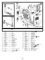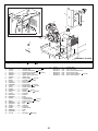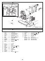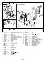
1
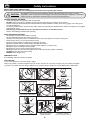
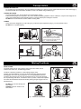
GB Operators Manual
- Spare Parts Book
4
18
870/00002/1
1
EC DECLARATION OF CONFORMITY / DECLARATION CE DE CONFORMITE /
DECLARACIÓN DE CONFORMIDAD CE / DECLARAÇÃO CE DE CONFORMIDADE /
EG-VERKLARING VAN OVEREENSTEMMING / EF
OVERENSSTEMMELSESERKLÆRING
GB
F
We, Belle Group Sheen UK, Sheen, Nr. Buxton, Derbyshire, SK17 0EU, GB, hereby certify that if the product described within this certificate is bought from an
authorised Belle Group dealer within the EEC, it conforms to the following EEC directives: 98/37/EC (This directive is a consolidation of the original machinery directive
89/392/EEC), Electromagnetic Compatibility Directive 89/336/EEC (as amended by 92/31/EEC & 93/68 EEC). The low voltage directive 73/23/EEC, BS EN ISO
12100-1:2003 Safety of machinery and associated harmonised standards, where applicable. Noise emissions conform to directive 2000/14/EC Annex VI, for machines
under article 12 the notified body is AV Technology Limited, AVTECH house, Birdhall Lane, Cheadle Heath, Stockport, Cheshire, SK3 0XU, GB.
Noise Technical Files are held at the Belle Group Head Office address which is stated above.
Nous soussignons, Belle Group Sheen UK, Sheen, Nr Buxton, Derbyshire, SK17 0EU, GB, certifions que si le produit décrit dans ce certificat est acheté chez un
distributeur autorisé Belle Group au sein de la CEE, il est conforme aux normes CEE ci-après: 98/37/CE (Cette norme est une codification des normes de la machine
d'origine 89/392/CEE), Norme compatible pour l'électromagnisme 89/336/CEE (modifié par 92/31/CEE et 93/68/CEE). Caractéristiques basse tension 73/23/CEE, BS EN
ISO 12100-1:2003, Norme de sécurité des machines et des critères associés et configurés, si applicable. Les émissions de bruit sont conformes à la directive
2000/14/EC Annexe VI pour machines , article 12, l’objet mentionné est AV Technology Mimited, AVTECH House, Birhall Lane, Cheadle Heath, Stockport, Cheshire,
SK3 0XU, GB.
Les dossiers techniques sur les émissions sonores des machines sont détenus au siège social de BELLE GROUP à l’adresse ci-dessus.
E
La Sociedad, Belle Group Sheen UK, Sheen, Nr. Buxton, Derbyshire, SK 17 OEU, GB, por el presente documento certifica que si el producto descrito en este
certificado es comprado a un distribuidor autorizado de Belle Group en la CEE, este es conforme a las siguientes directivas: 98/37/CE de la CEE (Esta directiva
consolida la directiva inicial sobre maquinaria 89/392/CEE), Directiva 89/336 CEE sobre Compatibilidad Electromagnética (según enmiendas 92/31/CEE y 93/68 CEE),
Directiva sobre Bajo Voltaje 73/23/CEE, BS EN ISO 12100-1:2003 de Seguridad de Maquinaria y Niveles armonizados estándares asociados donde sean aplicables.
Emisión de Ruídos conforme a la Directiva 2000/14/CE Anexo VI para máquinas bajo artículo 12 la mencionada unidad está AV Technology Limited, AVTECH House,
Birdhall Lane, Cheadle Heath, Stockport, Cheshire, SK3 OXU, GB.
En La Sede Central de Belle Group existen Archivos Técnicos con contenido referente a Niveles de Ruido.
P
O signatário, Belle Group Sheen UK, Sheen, Nr Buxton, Derbyshire, SK 0EU, GB, pelo presente, declara que se o produto descrito neste certificado foi adquirido a
um distribuidor autorizado do Belle Group em qualquer país da UE, está em conformidade com o estabelecido nas seguintes directivas comunitárias: 98/37/EC (esta
directiva é uma consolidação da directiva de maquinaria original 89/392/EEC), Directiva de Compatibilidade Electromagnética 89/336/EEC (conforme corrigido pelas
92/31/EEC & 93/68 EEC). A directiva de baixa voltagem 73/23/EEC, BS EN ISO 12100-1:2003 Segurança da maquinaria e às normas harmonizadas afins se aplicáveis.
As emissões de ruído respeitam e estão dentro das directivas para máquinas 2000/14/EC Anexo VI, artigo 12, sendo o organismo notificado AV Technology Limited,
AVTECH house, Birdhall Lane, Cheadle Heath, Stockport, Cheshire, SK3 0XU, GB.
A informação técnica sobre níveis sonoros está disponivel na Sede da Belle Group na morada acima mencionada.
NL
Ondergetekende, Belle Group Sheen UK, Sheen, Nr. Buxton, Derbyshire, SK17 OEU, GB, verklaren hierbij dat als het product zoals beschreven in dit certificaat is
gekocht van een erkende Belle Group dealer binnen de EEG, het voldoet aan de volgende EEG richtlijnen: 98/37/EC (Deze richtlijn is een opvolger van de orginele
Machinerichtlijn 89/392/EEG), Electromagnetische Compatability Richtlijn 89/336/EEG ( geamendeerd door 92/31/EEG & 93/68 EEG). De Laagspannings Richtlijn
72/23/EEG, BS EN ISO 12100-1:2003 Veiligheid van Machines en hieraan gekoppelde geharmoniseerde Standaarden, waar deze van toepassing is. Rumoer emissions
passen voor richtlijn EC Zijgebouw VI , voor toestel onder stuk 12 naar de notified troep zit AV Technology Limited, AVTECH house, Birdhall Lane, Cheadle Heath,
Stockport, Cheshire, SK3 OXU, GB
Worden de Technische Dossiers van het lawaai gehouden op het adres van het Hoofdkantoor van de Groep Belle dat hierboven ' wordt verklaard.
DK
Vi, Belle Group Sheen UK, Sheen, Nr. Buxton, Derbyshire, SK17 0EU, GB, erklærer hermed, at hvis det i dette certifikat beskrevne produkt er købt hos en autoriseret
Belle Group forhandler i EU, er det i overensstemmelse med følgende EØF-direktiver: 98/37/EF, 73/23/EØF (som ændret ved 93/68/EØF), 89/336/EØF (som ændret ved
92/31/EØF), 93/68/EØF og tilknyttede, harmoniserede standarder, hvor relevant. Støjniveauet er i overensstemmelse med direktiv 2000/14/EF, bilag VI gældende for
maskiner under paragraf 12. Det bemyndigede organ er AV Technology Limited, AVTECH house, Birdhall Lane, Cheadle Heath, Stockport, Cheshire, SK3 0XU,
Storbritanien.
PRODUCT TYPE .................
TYPE DE PRODUIT..............
TIPO DE PRODUCTO ..........
TIPO DE PRODUCTO .........
MODEL.................................
MODELE...............................
MODELO ..............................
MODELO..............................
SERIAL No...........................
N° DE SERIE ........................
N° DE SERIE........................
NO. DE SÉRIE .....................
DATE OF MANUFACTURE.
DATE DE FABRICATION .....
FECHA DE FABRICACIÓN..
DATA DE FABRIC
SOUND POWER LEVEL
MEASURED.........................
(GUARANTEED)..................
NIVEAU DE PUISSANCE
SONORE MESUREE............
(GARANTIE) .........................
NIVEL DE POTENCIA
ACÚSTICA MEDIDO ............
(GARANTIZADO) .................
NIVEL DE POTÊNCIA
DE SOM MEDIDO................
(GARANTIDO) .....................
WEIGHT...............................
POIDS...................................
PESO ....................................
PESO ...................................
PRODUCTTYPE ..................
PRODUKTTYPE ...................
MODEL.................................
MODEL .................................
SERIENUMMER...................
SERIENR. .............................
FABRICAGEDATUM............
FREMSTILLINGSDATO .......
GEMETEN
GELUIDSSTERKTENIVEAU
(GEGARANDEERD) ............
LYDEFFEKTNIVEAU
MÅLT ....................................
(GARANTERET)...................
GEWICHT.............................
VÆGT...................................
Signed by:
Signature:
Medido por:
Assinado por:
Getekend door:
Uunderskrevetaf:
Ray Neilson
Managing Director - On behalf of BELLE GROUP (SHEEN) UK.
Le Directeur Général - Pour le compte de la SOCIETE BELLE GROUP (SHEEN) UK.
Director Gerente - En nombre de BELLE GROUP (SHEEN) UK.
Director-Geral - Em nome de BELLE GROUP (SHEEN) UK.
Algemeen Directeur - Namens BELLE GROUP (SHEEN) UK.
Administrerende direktør – På vegne af BELLE GROUP (SHEEN) UK.
2
3
GB
Engine Warranty
The engines installed in the Belle Premier XT range of mixers carry a 12 month warranty. Any problems encountered with the engine,
during the warranty period should be dealt with by the relevant approved engine dealer, nearest to yourself.
If you require the name of your nearest approved engine dealer, a full listing is available on request from Belle.
Serial Numbers
ATTENTION!
Make a note of the serial numbers of your machine and always quote them in any communication with a
Belle Group Dealer.
MACHINE SERIAL NUMBER
ENGINE / MOTOR SERIAL NUMBER
Introduction
GB
Congratulations on the purchase of this quality concrete mixer from the Belle Group range.
This machine is manufactured to conform to the EEC directives currently in force and is
issued with a declaration of conformity and therefore displays the CE mark, applicable in territories where they are enforced.
Read this manual carefully, observing all operating and safety instructions before, during and after using your machine. Maintain your
machine in good working order.
When maintaining this machine only the manufacturer’s original spare parts may be
used. The user will lose any possible claims if replacement parts used are other than the makers original spare parts.
Retain this manual with your machine for future reference.
SAFETY AND ACCIDENT PROTECTION
Operating Instructions :
All persons who apply, assemble, operate, start, control, maintain or repair this machine must read and understand these operating
instructions.
Owner Responsibility :
The owner must ensure that only qualified persons operate, maintain, or repair this machine.
Storage :
When not in use, store in a dry, locked place. Keep away from children.
Operation for the Intended Purpose :
Mixers are intended for the production of concrete, mortar and plaster. The mixer must be used for its intended purposes and is not
suitable for the mixing of flammable or explosive substances. The mixers must not be used in an explosive atmosphere.
MAINTENANCE AND REPAIRS
Only authorised dealers should repair the mixer, and within the requirements of the CE mark (where applicable), where no deviation to
the original specification must take place.
WARNING
Any maintenance and repairs carried out, to any of the electric motors components must be undertaken
by a qualified electrician.
REPLACEMENT PARTS
Contact your nearest Belle Group dealer. When ordering replacement parts, please quote the product type, serial number & engine/
motor model. Detail the part required in conjunction with the parts list provided, indicating the Page Number, Item Number and
quantity required.
4
GB
Contents
Page number
Engine Warranty ......................................................................................................................................................................................... 4
Introduction ................................................................................................................................................................................................ 4
Warning Symbols ...................................................................................................................................................................................... 5
Plug Wiring ................................................................................................................................................................................................ 5
Safety Instructions ..................................................................................................................................................................................... 6
Transportation ........................................................................................................................................................................................... 7
Mixing Positions ........................................................................................................................................................................................ 7
Mixing Hints ................................................................................................................................................................................................ 8
Functional Controls ................................................................................................................................................................................... 9
Operating Instructions - Electric Motors ................................................................................................................................................... 10
Operating Instructions - Yanmar L48 ........................................................................................................................................................11
Operating Instructions - Lister Petter Build 10 & 32..................................................................................................................................11
Maintenance Instructions ......................................................................................................................................................................... 12
Lister Petter 10 & 32 Checks & Maintenance schedule ......................................................................................................................... 13
Yanmar L48 Checks & Maintenance schedule ....................................................................................................................................... 14
Wiring Diagram......................................................................................................................................................................................... 15
Technical Data .......................................................................................................................................................................................... 16
Belle Group reserves the right to change machine specification without prior notice or obligation.
Warning Symbols
GB
WEAR EAR PROTECTION
FIRE AND EXPLOSIVE RISK
READ OPERATOR
MANUAL
WEAR EYE PROTECTION
WEAR PROTECTIVE
FOOTWEAR
LIFTING POINT
WARNING - IMPORTANT
The Premier range of mixers are intended for industrial use, the following plug types are supplied fitted to the product:
110V motor - 32 amp rated BS4343 plug type.
230V motor - 16 amp rated BS4343 plug type.
415V motor - 32 amp rated BS4343 plug type.
Fitting a plug - WARNING THIS PRODUCT MUST BE EARTHED
IMPORTANT: The wires in the mains lead are coloured in accordance with the following code:
GREEN / YELLOW = EARTH, BLUE = NEUTRAL, BROWN = LIVE
The wire which is coloured Green and Yellow must be connected to the terminal in the plug marked E or coloured Green and Yellow.
The wire which is coloured Brown must be connected to the terminal in the plug marked L or coloured Red. The wire which is
coloured Blue must be connected to the terminal in the plug marked N or coloured Black.
Always ensure before connecting to the supply that the supply voltage is the same as the rated voltage marked on the motor.
5
Safety Instructions
GB
READ THESE SAFETY INSTRUCTIONS
Please read and understand all running/safety instructions before operating this machine.
CAUTION
The appliance is not to be used by children or persons with reduced physical, sensory or mental
capabilities, or lack of experience and knowledge unless they have been given supervision or instruction.
Children should be supervised to ensure that they do not play with the appliance.
BEFORE STARTING THE MIXER
- Check that all guards are in position and correctly fitted.
- DO NOT wear loose clothing or jewellery that may become entangled in the workings of this machine.
- Suitable clothing as follows should meet relevant EEC/local safety standards: overalls, work boots, goggles, face mask, gloves
and ear defenders etc.
- On electric powered mixers, ensure that any trailing cable is protected against damage and not liable to be tripped over or trapped
- underneath the mixer.
- Belle strongly recommends the use of a Residual Current Device on 220-240v electrics.
- Remove all packaging material before operating.
WHEN OPERATING THE MIXER
- Keep engine housing lid closed whilst it is mixing.
- Keep unauthorised persons away from mixing drum.
- Keep area around the mixer clear of obstructions which could cause persons to fall onto moving parts.
- Always ensure mixer is on level ground before mixing.
- Ensure rear wheel brakes are applied before operating the mixer.
- DO become familiar with the controls before operating this machine.
- DO ensure plenty of ventilation when running the diesel engines in a confined area.
- DO replace any worn/damaged warning decals.
- DO ensure the drum is rotating while emptying the mixer.
- DO always switch off and remove the plug from the socket if leaving the machine unattended.
- DO NOT transport this mixer when mixing.
- BEWARE of the danger zones.
EMERGENCY STOP
See Operating Instructions Section for details.
FIRE FIGHTING
If your mixer catches fire, turn off the electric supply.
Using a dry powder or C02 fire extinguisher put out the fire. If the fire can not be put out, keep away and call the fire brigade.
If you are in any doubt about the safety condition of your machine, please consult your nearest Belle dealer or Belle direct.
DRUM ROTATES ANTI-CLOCKWISE
DO NOT PUT ANY PART OF YOUR
BODY IN THE DRUM
ALWAYS WORK WITHIN THE
RATED CAPACITY
ALWAYS MIX IN WELL VENTILATED
PLACES EXHAUST FUMES CAN KILL
DO NOT PUT SHOVEL IN THE DRUM
ALWAYS MIX ON LEVEL GROUND
DO NOT FILL WITH FUEL OR
LUBRICATION OILS WHILST
ENGINE IS RUNNING
6
LOAD AND UNLOAD FROM THE
TRANSPORT CORRECTLY
(See Transport Section in Manual)
GB
Transportation
LOADING BY FORK LIFT
- For normal site to site transporting, the usual method of loading into a pick-up truck or trailer should be used. A fork socket (Fig 3)
is located beneath the main frame to enable the mixer to be loaded using a forklift (Fig 1).
LOADING BY CRANE
- To expose the lifting eye, turn the drum so it is facing down, (Fig 2).
- Ensure the lifting ropes are inspected to the current Health and Safety guidelines and are sufficient to carry the total weight of the
mixer. See technical data. Ensure the lifting hook is correctly located prior to lifting the machine.
- DO NOT stand underneath the machine whilst it is being lifted.
TOWING
- These mixers are designed for on site towing only, maximum speed 5mph/8 kmh (Fig 4), for short periods of time.
- DO NOT tow on a public highway.
If the fork is not the same depth
as the socket it may be necessary
to pack under the fork with wood to
keep the load stable.
Fig 3
Fig 1
5mph
8kmh
Fig 2
Fig 4
GB
Mixing Positions
DRUM TILTING
The hand wheel gives an easy positive control of the drum which can be
locked in the stored, mix, and discharge position.
The drum is locked in position by a self locating plunger which
engages into the handwheel. To move the drum the locating plunger must be
dis-engaged, this is done by pressing down on the footpedal (this is situated
just above the pivoting front axle), the handwheel will now move freely allowing
the re-positioning of the drum, to relock the drum in position, release the footpedal
and rotate the handwheel until the self-locating locking plunger engages into the
handwheel ring.
-
Fig 5
MIXING POSITIONS
DO NOT put your hand through the
hand wheel.
ALWAYS keep both hands on the
hand wheel.
Fig 6
STORAGE POSITIONS
7
Fig 7 DISCHARGE POSITIONS
GB
Mixing Hints
Mix Ratios
The correct mix ratio (cement:sand:stone) depends on the type of application; harder concrete requires more cement, rougher
applications require more aggregate. The ratios given below are guidelines: best proportions may depend on the quality of sand/stone
used.
First put in the water - around 7 litres (1½ gallons), using more or less depending on the type of mix required. Add some aggregate
before adding cement, to avoid sticking. Work consistently to the ratio of ingredients for whatever type of concrete mix you are
working to.
Getting A Good Mix
The approximate mixing time for concrete is 2-4 minutes from when all the material (including the water) has been added - overmixing can reduce strength and cause segregation of the coarser aggregates.
Beware of low grade aggregates; these will only lead to trouble later on with sinking and frost spoiling the appearance of the pour.
Also do not get the concrete mix too wet as this can reduce strength and make it less able to withstand weathering.
Looking After Your Mixer
Never throw material into the mixer - trickle it steadily over the rim or it will stick firmly to the back of the drum and can only be
dislodged by stopping the mixer.
Keep your mixer clean - material left in the drum will harden, and attract more on each use until the mixer is useless.
Do not throw bricks into a mixer drum to clean it out. The best method is a mix of 1” (2½cm) gravel and clean water - use plenty of it,
as this will do the job in half the time.
APPLICATIONS
QUANTITIES
CEMENT
1
SAND
2
STONE
4
FOUNDATIONS
1
3
6
ROUGH MASS CONCRETE
1
4
8
WATERTIGHT FLOORS,TANKS PITS ETC.
1
1.5
3
MOST ORDINARY
8
GB
Functional Controls
Mixing Drum
Handwheel
Rear Opening
Door
Door Stay
Park Brake
Lever
Pivoting Axle
Lister Emergency
Stop
Towbar
Handwheel
Locking Plunger
Yanmar Engine
Charge Light
Yanmar
Emergency
Stop
Electric
Emergency
Stop
Foot Pedal
9
GB
1.
Operating Instructions
ELECTRIC MOTOR : VARIANTS
STOPPING
1.1 Depress RED Button
(or on/off toggle
switch if fitted to the Off
position) to stop mixer
(Fig B).
STARTING
1.2 Lift rear door.
1.3 Feed supply cable out
through the rear of the
mixer and plug into
power supply.
1.4 Depress GREEN
Button (or on/off toggle
switch if fitted to the On
position) to start mixer
(Fig A).
-
B
A
C
Ensure supply cable is safely stored before moving mixer.
Keep rear door shut when mixer is running
EMERGENCY STOP
1.5 Depress large RED Button, situated on top left hand side of power unit housing (Fig C).
2.
YANMAR (ELECTRIC START)
STOPPING
2.1 Press Red Lever (Fig D).
-
Note: Red indicator light
glows when engine charging
system fails.
Ensure that when machine
is not in use that ignition is
switched OFF, or battery
failure may occur.
PUL
L
TO
STO
P
E
D
Closed
EMERGENCY STOP
2.2 Pull the handle on the
side of the power unit box to
STOP the machine (Fig E).
COLD STARTING
2.3 Lift rear door.
-
F
Open
Open fuel cock if fitted (Fig F).
2.4 In cold starting situations the engine requires 2cc of engine oil (10w-30) to be applied using oil applicator. The oil
should be inserted into the engine by removing the rubber plug on the priming port, ensure the plug is replaced (Fig G).
2.5 Ensure the Emergency Stop Button is pushed in (Fig H).
2.6 Set the engine speed lever (situated on the left hand side of engine) to the run position (Fig I).
2.7 Turn ignition key clockwise until engine turns over, release key whenengine starts. If engine fails to start, repeat process of cold start.
-
Note: Once an attempt to start the engine has failed, before re-trying the key must be turned back to the OFFposition.
DO NOT operate with rear door open.
WARM STARTING
2.8 Repeat process above from 2.5.
10
GB
Operating Instructions
3.
YANMAR (RECOIL START) Back Up to Electric Start
STOPPING
3.9 Press red lever (Fig D).
EMERGENCY STOP
3.10 Pull the handle on
the side of the
power unit box to
STOP the
machine (Fig E).
COLD STARTING
3.11 Lift rear door.
G
I
H
Open fuel cock if fitted (Fig F).
3.12 In cold starting situations the engine requires 2cc of engine oil (10w-30) to be applied using oil applicator. The oil should be
inserted into the engine by removing the rubber plug on the priming port, ensure the plug is replaced (Fig G).
3.13 Ensure the Emergency Stop Button is pushed in (Fig H).
3.14 Set the engine speed lever (situated on the left hand side of engine) to the run position (Fig I).
3.15 Pull out the recoil starting handle to the point where you feel a strong resistance, then return back the install position. Push over
the decompression lever (top right hand side of engine) this will return automatically when the recoil handle is pulled for
the second time.
3.16 Apply both hands to the recoil starting handle and pull briskly, if engine does not start repeat from 3.15.
-
DO NOT operate with rear door open.
WARM STARTING
3.17 Repeat process above from 3.14.
4.
-
LISTER PETTER : CRANK HANDLE START
J
L
N
K
M
O
Caution should be taken when starting unit, always use Anti-Kick Back Starting Handle.
Ensure handle is correctly engaged in crank barrel (Fig J) before cranking engine.
Ensure Oil & Fuel levels are checked daily before starting engine.
Ensure rear door stay is correctly engaged before working in power unit area.
Keep rear door closed when mixer is running.
4 STOPPING
4.1 Open rear door and move Start / Stop lever to the STOP position (Fig L).
COLD STARTING
4.2 Lift rear door.
4.3 Lift Safety Button up, locate Starting Handle in crank barrel and turn until handle engages (Fig J).
4.4 Engage Start / Stop lever into START position (Fig K).
4.5 Push decompression lever into vertical position and hold (Fig L).
4.6 Crank the engine as fast as possible and move the de-compressor lever into the running position whilst continuing to crank briskly
until the engine starts.
4.7 Once the engine starts remove handle and place back in storage, then move Start/Stop lever into the RUN position(Fig M).
WARM STARTING
4.8 Follow the above instructions from 2.2 to 2.6, however start engine with the Start / Stop lever in the RUN position.
EMERGENCY STOP
4.9 Pull handle on top of power unit box (Fig O).
11
GB
Maintenance Instructions
Before starting any maintenance or repairs, stop engine or switch off motor, and isolate from the main power supply.
On completion of maintenance, check that the mixer functions correctly and that all guards are correctly fitted.
ELECTRIC MOTORS
All portable electric appliances are dangerous if abused. This machine will only operate on one voltage. Check the power supply to
ensure it corresponds to the voltage as stamped on the motor. Make sure that the motor is switched off before you plug it into the
power supply.
220-240v -Always use a Residual Current Device (“RCD”), (earth leakage trip), plugged directly into the 220-240v socket. If using an
extension cable, plug it directly into the RCD.
110v -When using a portable transformer it must have a minimum output of 6.3kw and be continuously rated.
-
DO NOT use an extension cable between the transformer and the power supply.
The symbols on the ON/OFF switch are 0=OFF and I=ON in accordance with international standards.
If the supply cord is damaged, it must be replaced by a special cord or assembly available from the manufacturer or its
service agent. (See Wiring Diagram on Page 15.)
EXTENSION CABLES
If you need to use an extension cable it must be no longer than 30 metres (100 feet) in length. The wire section for 220-240v must be
2.5mm2. The wire section for 110v must be 4mm2 on 100XT and 6mm2 on other models. Ensure that the extension cable is
carefully laid out avoiding liquids, sharp edges and places where vehicles might run over it. Unroll it fully or it will overheat and could
catch fire. Make sure that any extension cable connections are dry and safe.
COMBUSTION ENGINES
- Be aware of exhaust venting directions.
The engine needs a regular oil check.Try not to run low on fuel as this may result in sediment from the bottom of the tank doing
damage to the injector and pump. Repairs and rectification of pipework and components affected by contaminants in fuel
cannot be accepted as warranty, neither will faults caused or contributed to by the machine running out of fuel. You may
need to bleed the fuel system free of air before starting. For initial engine fill or top up use a suitable engine oil of a 10W/30 grade. In
your own interests read the makers instruction leaflet issued with the machine before starting up.
DRUM (Removal and Fitment)
This can be instantly removed by unscrewing it counter clockwise in the vertically up position. Lift the drum off the machine using a
fork lift, with the forks under the base of the drum. When replacing make sure that the drum shaft is greased before it is fully
screwed down on to the shoulder of the shaft, ensure the drum is fully screwed down on to the shoulder or damage will occur. Take
care when screwing on the drum, spinning on fast may damage the gearbox.
CLEANING
Wipe off any external material. DO NOT use petrol, turpentine, lacquer or paint thinner, dry cleaning fluids or similar products. Never
let any liquids near the engine/motor. Use 1” gravel and clean water to clean the inside of the drum.
-
DO NOT use bricks etc. as this will damage the drum.
DRIVE BELT
- DO NOT try to adjust with the engine / motor running.
- DO NOT run slack.
- DO NOT operate machine with guards removed.
The drive belt is under constant even tension by a spring loaded jockey, this requires no attention. The bearings are sealed for life.
GEARBOX OIL
Note: The original gearbox oil is a synthetic oil and must not be mixed with a mineral oil.
Full gearbox fill 1.0 ltrs, check regularly.
The gearbox was originally filled with: Total :- Transmission W 75W/90 viscosity
Equivalent oils:
Shell :- Tivela SA, Tivela WA, Dentax W
Texaco :- Synlube 90
Esso :- GX 75W/90
Mobil :- Glygoyle 22
Castrol :- WM or Alpha SN150
Caltex :- Synthetic gear lubricant
LUBRICATION AND RUNNING
See Maintenance Schedule Section and Operating Instructions.
Remember that diesel engines vibrate more, so regularly check all nuts and bolts are tight.
12
Check the fuel & lubricating oil levels
9
Check for oil & fuel leaks
Clean, or replace, the air cleaner element under very dusty conditions
Check the condition of the battery, if fitted
9
9
Hrs
Every 1000
Every 500 Hrs
Lister-Petter 32 & 10 Engines
Every 250 Hrs
Every 125 Hrs
Daily
To help assist engine running-in, all engines are despatched with an initial fill lubricating
oil which must be changed after 100 hours.
All subsequent oil changes must be as specified below.
Every 2000
Hrs
GB
Checks and Maintenance
9
9
9
Clean or replace the air cleaner element under moderately dusty conditions
Drain the sump and refill with new oil of the correct type and specification as given in
engine handbook
9
9
9
Clean or replace the injectors if the exhaust is dirty
Renew the fuel filter element if the fuel being used is not perfectly clean
Replace the air cleaner element
9
9
9
9
Examine exhaust & induction systems for leaks, damage or restrictions
Renew the fuel filter element
Check the battery charge winding system; refer to Workshop Manual
Check the valve clearances
Decarbonise if the engine performance has deteriorated
Clean the cylinder barrel and head fins
9
9
9
Clean the banjo union at the cylinder head end of oil feed pipe
Drain, flush and refill the fuel tank
9
9
Mixer
Daily
50
Hours
250
Hours
500
Hours
1000
Hours
9
9
9
Grease Yoke Pivot
Grease Tipping Gear (10 Operations of Grease Gun)
9
Remove Drum and Grease Shaft
9
9
Check Nuts and Bolts
Check Gearbox Oil
9
Grease Layshaft, Grease Nipple
9
Check Components for Leaks
13
GB
Yanmar L48 Engine
April ‘04
Check the fuel level and refill.
Drain the fuel tank
* Clean the fuel filter
* Replace the fuel filter
Check for fuel / oil leakage
- Before Operation
9
9
9
- After Operation
99
99
* Fuel injection nozzle, Check the injection condition
* Check the fuel injection timing
* Check the fuel injection pump
Check the lube oil level in the oil pan and refill
Replace the lube oil
Clean lube oil filter
Check for lube oil leakage
Check the valve clearances
* Check the air cleaner element
* Replace the air cleaner element
Check the battery liquid level and refill
Check the warning lamps
Adjusting the intake and exhaust valve clearance
Every year or
Every 1000 Hrs
Parts with an asterisk mark “ * “ are related to the CARB ULG rules.
Every 6 months or
Every 400 Hrs
Items marked “99“ should be serviced by an authorized YANMAR
dealer, unless the owner has proficient mechanical ability and the proper tools.
Every 3 months or
Every 200 Hrs
Every month or
Every 500 Hrs
Checks and Maintenance
99
- Before Operation
1st time
2nd & after
1st time
2nd & after
- After Operation
9
9
9
- Before Operation
- When Engine Is Started
99
Mixer
Daily
50
250
500
1000
Hours
Hours
Hours
Hours
9
9
9
Grease Yoke Pivot
Grease Tipping Gear (10 Operations of Grease Gun)
9
Remove Drum and Grease Shaft
9
9
Check Nuts and Bolts
Check Gearbox Oil
9
Grease Layshaft, Grease Nipple
9
Check Components for Leaks
14
GB
Wiring Diagram
SWITCH
E-STOP
CABLE
POWER
FROM
SUPPLY
BROWN
BROWN
BLUE
BLUE
BROWN
L2
L1
L3
T3
YELLOW / GREEN
T2
BLUE
T1
BROWN
C1
BLUE
95
BROWN
96
O/L
BROWN
BLUE
BROWN
MOTOR
THERMAL
PROTECTION
POWER
TO MOTOR
MOTOR
BROWN
BLUE
THERMAL
PROTECTION
BROWN
BROWN
BLACK
BROWN
RED
BLUE
WHITE
WHITE
YELLOW
CBB
CD
BLUE
WHITE
YELLOW / GREEN
MOTOR
THERMAL
PROTECTION
POWER
FROM
SWITCH
15
GB
Technical Data
G
H
C
D
E
F
J
A
B
100XT
150XT
175XT
200XT
A - OVERALL LENGTH (MM)
B - OVERALL WIDTH (MM)
C - OVERALL HEIGHT (MM)
1665
900
1468
1665
900
1568
1890
900
1049
1890
900
1077
D - LOADING HEIGHT (MM)
E - DISCHARGE HEIGHT (MM)
F - DIAMETER OF WHEELS (MM)
613
350
2100
607
350
2100
713
350
2200
680
350
2200
G - OVERALL LENGTH - DOOR OPEN (MM)
H - OVERALL HEIGHT - DOOR OPEN (MM)
J - WHEEL BASE
1950
1120
1120
1950
1120
1120
1950
1520
1520
1950
1520
1520
CUBIC FEET IN/OUT
MIXED BATCH OUTPUT (LTR)
5/3.5
110
7/5
160
8/6
180
10/7
220
MAX DRUM CAPACITY (LTR)
MAX DRY MIX DRUM CAPACITY IN (LTR)
DRUM SPEED (RPM)
250
160
19
300
220
19
350
250
19
400
310
19
ELECTRIC RANGE
UNLADEN WEIGHT (Kg)
100XT 150XT 175XT 200XT 100XT 150XT 175XT 200XT 100XT 150XT 175XT 200XT
305.5 314.5 322.5 325 303.5 312.5 320.5 323 305.5 314.5 322.5 325
NOMINAL VOLTAGE (V)
NOMINAL CURRENT (Amp)
NOMINAL POWER
VOLTAGE FREQUENCY (Hz)
MOTOR RPM
MOTOR PROTECTION
POWER CONSUMPTION (Kwh)
SOUND POWER LEVEL (LWA)
DIESEL RANGE
UNLADEN WEIGHT (Kg)
ENGINE MODEL
NOMINAL POWER (KW)
STARTING METHOD
FUEL CAPACITY
SOUND POWER LEVEL (LWA)
240
110
13.7
6.6
1.5
50
1430
1350
Thermal / NVR
1.5
87dB(A)
LISTER
YANMAR
100XT 150XT 175XT 200XT 100XT 150XT 175XT 200XT
367
376
392.5
395
334.5 343.5 350.5 353.5
LT1 (Build 32) LT1 (Build 10)
0.75
1.9
Hand Crank
5
L48
2.3
Electric / (Recoil Backup)
2.5
99 dB(A)
16
415
3.6
1500
17
1-01
14
24
1
25
27
26
4
5
2
22
17
7
21
20
7
18
5
15
19
16
6
8
13
9
19
FRAME ASSEMBLY - 100-150XT
(CORRECT AT 05/04)
23
1-01
Frame Assembly - 100-150XT
1
2
3
4
5
6
7
8
9
10
11
12
13
14
15
16
17
18
19
20
21
22
23
24
24A
24B
24C
25
25A
26
27
909/11200 ............. 1 .......... Frame (100/150XT)
909/12300 ............. 1 .......... Axle
8/20002 ................. 1
4/2001 ................... 3
909/11100 ............ 1
3/0006 ................... 6
4/0009 ................... 4
XS35 .................... 2
.......... Nut (M20)
.......... Washer (M20)
.......... Towbar
.......... Split Pin
.......... Washer (M26)
.......... Handle Grip
60/0284 ................. 4 .......... Wheel
909/20000 ............. 1 .......... Grease Nipple Assembly (
909/99996 ............. 4 .......... Spacer
909/17402 ............. 1 .......... Brake Bar
909/99998 ............. 1 .......... Lever
7/10015 ................. 1 .......... Screw (M10x65)
3/0044 ................... 2 .......... Spirol Pin
2/0027 ................... 1 .......... Spring
909/99997 ............. 1 .......... Spacer
74/0001 ................. 1 .......... Knob
909/17401 ............. 1 .......... Brake Cam
800/22600 ............. 1 .......... Decal Kit (100XT)
800/22700 ............. 1 .......... Decal Kit (150XT)
800/22800 ............. 1 .......... Decal Kit (175XT)
800/22900 ............. 1 .......... Decal Kit (200XT)
1/0519 ................. A/R ........ Orange Paint (Tin)
1/0507 ................. A/R ........ Orange Paint (Spray)
3/0049 ................... 1 .......... Split Pin
3/4034 ................... 1 .......... Cap
June’04)
18
1-02
14
24
24A
24B
24C
1
12
4
11
3
10
26
2
22
25
25A
5
17
7
21
20
7
18
5
15
19
16
6
8
13
9
19
FRAME ASSEMBLY - 175-200XT
(CORRECT AT 05/04)
23
1-02
Frame Assembly - 175-200XT
1
2
3
4
5
6
7
8
9
10
11
12
13
14
15
16
17
18
19
20
21
22
23
24
24A
24B
24C
25
25A
26
909/11600 ............. 1 ......... Frame (175/200XT)
909/12300 .............. 1 ......... Axle
909/99935 .............. 1 ......... Plate
8/20002 .................. 1 ......... Nut (M20)
4/2001 .................... 3 ......... Washer (M20)
909/11100 ............. 1 ......... Towbar
3/0006 .................... 6 ......... Split Pin
4/0009 .................... 4 ......... Washer (M26)
XS35 ..................... 2 ......... Handle Grip
7/10010 .................. 2 ......... Screw (M10x30)
4/1005 .................... 2 ......... Washer (M10)
8/10001 .................. 2 ......... Nut (M10)
60/0284 .................. 4 ......... Wheel
909/20000 .............. 1 ......... Grease Nipple Assembly (
909/99996 .............. 4 ......... Spacer
909/17402 .............. 1 ......... Brake Bar
909/99998 .............. 1 ......... Lever
7/10015 .................. 1 ......... Screw (M10x65)
3/0044 .................... 2 ......... Spirol Pin
2/0027 .................... 1 ......... Spring
909/99997 .............. 1 ......... Spacer
74/0001 .................. 1 ......... Knob
909/17401 .............. 1 ......... Brake Cam
800/22600 .............. 1 ......... Decal Kit (100XT)
800/22700 .............. 1 ......... Decal Kit (150XT)
800/22800 .............. 1 ......... Decal Kit (175XT)
800/22900 .............. 1 ......... Decal Kit (200XT)
1/0519 .................... A/R ..... Orange Paint (Tin)
1/0507 .................... A/R ..... Orange Paint (Spray)
3/0049 .................... 1 ......... Split Pin
June’04)
19
2-01
6
8
1A
3
2
6
16
17
18
8
1
7
3
19
9
12
10
11
11
13
14
15
5
4
2-01
Door Assembly
1
1A
2
3
4
5
6
7
8
9
10
11
12
13
14
15
16
17
18
19
(CORRECT AT 07/03)
909/10400 ............. 1 .......... Cover
909/19700 ............. 1 .......... Hewden Rear Door Assembly
800/99903 ............. 1 .......... Decal
PS071 .................. 2 .......... Cap
3/0008 ................... 8 .......... Rivet
908/10700 ............. 2 .......... Catch
3/0003 ................... 2 .......... Split Pin
909/17600 ............. 1 .......... Door Stay
4/10001 ................. 2 .......... Washer (M10)
3/0013 ................... 2 .......... Spirol Pin
8/8002 .................. 3 .......... Nut (M8)
4/8006 ................... 6 .......... Washer (M8)
909/99959 ............. 1 .......... Bracket
7/8008 ................... 3 .......... Screw (M8x16)
1-01 & 1-02 ................. (Item 24)
3/3000 ................... 2 .......... Pad
915/00131 ............. 2 .......... Stud
909/99806 ............ 1 .......... Infil Plate
4/8006 ................... 2 .......... Washer (M8)
8/8002 ................... 2 .......... Nut (M8)
20
3-01
1
2
17
10
18
19
3
4
5
11
7
12
12
5
4
13
4
14
16
6
5
8
15
9
(CORRECT AT 07/03)
3-01
Wheel Assembly
1
2
3
4
5
6
7
8
9
10
11
12
13
14
15
16
17
18
19
4/1601 ................... 1
2/0029 ................... 1
909/99910 ............. 1
8/10001 ................. 3
4/1005 ................... 7
7/10010 ................. 1
909/99926 ............. 1
9/10015 ................. 1
909/99929 ............. 1
9/10004 ................. 1
909/14800 ............. 1
50/000016 ............. 2
909/14900 ............. 1
7/12013 ................. 2
8/12001 ................. 2
4/1204 ................... 4
909/10500 ............. 1
4/1607 ................... 1
8/16003 ................. 1
.......... Washer (M16)
.......... Spring
.......... Plunger
.......... Nut (M10)
.......... Washer (M10)
.......... Screw (M10x30)
.......... Plunger Link
.......... Bolt (M10x150)
.......... Foot Pedal
.......... Bolt (M10x35)
.......... Pivot
.......... Composite Bush
.......... Tip Gear
.......... Screw (M12x35)
.......... Nut (M12)
.......... Washer (M12)
.......... Hand Wheel
.......... Washer (M16)
.......... Nut (M16)
21
4-01
20
1
6
21
17
2
4
18
3
5
5
15
16
14
13
9
19
8
7
25
12
22
23 24
10
11
(CORRECT AT 05/04)
4-01
Yoke Assembly
1
2
3
4
5
6
6A
7
8
9
9A
10
11
12
12A
13
14
15
15A
16
17
18
19
19A
19B
19C
20
21
22
22A
22B
22C
23
5-01 ............... 1 .......... Gearbox
909/99942 ............. 1 .......... Guard
7/6032 ................... 5
909/10700 ............. 1
909/12200 ............. 1
8/12003 ................. 1
4/1205 ................... 1
908/15700 ............. 1
909/99807 ............. 1
500/06100 ............. 1
PS022 .................. 1
908/15500 ............. 1
21/0163 ................. 1
909/99932 ............. 1
PS074 .................. 2
909/13100 ............. 1
909/19900 ............. 1
908/15900 ............. 1
50/000016 ............. 2
908/21200 ............. 1
909/18300 ............. 1
909/18400 ............. 1
909/18500 ............. 1
909/18600 ............. 1
800/10441 ............. 2
5-01 ............... 1
909/19100 ............. 1
909/19200 ............. 3
909/19300 ............. 3
909/19400 ............. 3
7/12017 ................. 9
24
25
.......... Screw (M6x12)
.......... Yoke (100/150XT)
.......... Yoke (175/200XT)
.......... Nut (M12)
.......... Washer (M12)
May’04)
.......... Pulley (
May’04)
.......... Pulley (
.......... Grease Nipple
.......... Circlip
.......... Drive Belt (
May’04)
.......... Drive Belt (
May’04)
.......... Spacer
.......... Bearing
May’04)
.......... Layshaft (
.......... Layshaft (
May’04)
.......... Cover
.......... Bush
.......... Cover
.......... Drum (c/w Paddles) (100XT)
.......... Drum (c/w Paddles) (150XT)
.......... Drum (c/w Paddles) (175XT)
.......... Drum (c/w Paddles) (200XT)
.......... Decal Danger Zone
.......... Plate
July’02)
.......... Paddle Kit (100XT) (
.......... Paddle Kit (150XT) (
July’02)
Oct’02)
.......... Paddle Kit (175XT) (
Aug’02)
.......... Paddle Kit (200XT) (
.......... Screw (M12 x 30))
22
4/1201 ................... 9 ........... Washer (M12)
8/12001 ................. 9 .......... Nut (M12)
5-01
2
1
32
4
5
3
27
6
7
28
29
26
8
23
9
25
31
17
18
19
30
20
21
14
10
24
11
16
15
22
13
12
(CORRECT AT 09/05)
5-01
Gearbox Assembly
1
1A
1B
1C
2
3
4
5
6
7
8
9
10
11
12
12A
13
14
15
15A
16
17
18
19
20
21
22
23
24
25
26
27
28
909/16100 .........1 ......Gearbox Assy (100/150XT) (
909/13000 .........1 ......Gearbox Assy (175/200XT) (
909/20200 .........1 ......Gearbox Assy (100/150XT) (
909/20300 .........1 ......Gearbox Assy (175/200XT) (
7/12014 .............4 ......Bolt (M12x40)
XS01 ................1 ......Bung
908/14100 .........1 ......Decal
PS111 ..............1 ......Cover
5/0022 ...............1 ......Seal
PS002 ..............1 ......Bearing
909/17300 .........1 ......Mainshaft
5/0044 ...............1 ......Seal
909/13001 .........1 ......Case
5/0043 ...............1 ......Gasket
909/15000 .........1 ......Wormshaft (100/150XT)
909/12800 .........1 ......Wormshaft (175/200XT)
908/99901 .........1 ......Key
53/0010 .............2 ......Bearing
909/15100 .........1 ......Tube Carrier (100-150XT)
909/12900 .........1 ......Tube Carrier (175-200XT)
7/8012 ...............4 ......Bolt (M8x25)
PS013 ..............2 ......Bearing
5/0015 ...............1 ......Seal
909/12904 .........1 ......Spacer
PS016 ..............1 ......Seal
MS22 ................1 ......Circlip
1/0120 .............A/R ....Oil
53/0004 .............1 ......Bearing
909/12902 .........1 ......Spacer
7/8049 ...............3 ......Screw (M8x16)
7/12004 .............4 ......Bolt (M12x25)
8/8002 ...............3 ......Nut (M8)
908/16000 .........1 ......Plate
PM40005925)
PM40005925)
PM40005926)
PM40005926)
23
29
30
31
32
909/99995 .........1 ......Plate
909/12903 .........1 ......Spacer
3/9003 ...............1 ......Circlip
5/0067 ...............1 .......Seal
6-01
12
43
41
40
1
16
42
17
39
3
4
2
16
14
17
46
38
15
36
44
45
37
32
5
6
18
35
33
34
7
48
47
22
21
19
23
20
8
24
25
22
23
10
26
28
11
9
Engine Assembly (Lister
1
2
3
4
5
6
7
8
9
10
11
12
13
14
15
16
17
18
19
20
21
21A
22
23
24
25
26
27
28
29
30
29
27
30
31
(CORRECT AT 04/02)
6-01
July’02)
6/0003 ................... 1 .......... Blank
32/0116 ................ 1 .......... Hose
3/1010 ................... 1 .......... Clip
3/0043 ................... 1 .......... Rivet
6/0020 ................... 1 .......... Adaptor
5/0020 ................... 1 .......... Seal
39/1220 ................. 1 .......... Hose Kit
21/0107 ................. 1 .......... Stop Cable
2/0010 ................... 1 .......... Ring
908/21800 ............. 1 .......... Lever
7/4002 ................... 2 .......... Screw (M4)
PS087 .................. 1 .......... Air Filter (Build 32)
909/14100 ............. 1 .......... Exhaust (Build 32)
9/6001 ................... 2 .......... Bolt (M6x16)
4/6005 ................... 2 .......... Washer (M6)
7/8008 ................... 3 .......... Bolt (M8)
4/8003 ................... 3 .......... Washer (M8)
908/14200 ............. 1 .......... Air Filter (Build 10)
908/18600 ............. 1 .......... Fuel Filter
908/22500 ............. 1 .......... Handle
908/20800 ............. 1 .......... Engine (Build 32)
908/20900 ............. 1 .......... Engine (Build 10)
8/12001 ................. 8 .......... Nut
4/1205 .................. 12 ......... Washer (M12)
July’02)
4/1201 .................. 24 ......... Washer (M12) (
July’02)
909/99975 ............. 4 .......... Spacer (
909/99986 ............. 1 .......... Engine Deck (
July’02)
909/99980 ............. 1 .......... Spacer (
July’02)
9/10004 ................. 1 .......... Bolt (M10x35) (
July’02)
4/1005 ................... 2 .......... Washer (M10)
8/10001 ................. 1 .......... Nut (M10)
31
32
33
34
35
36
37
38
39
40
41
42
43
44
45
46
47
48
-
24
9/12018............4 ............Bolt (M12x100) (
July’02)
PS040 ..............1 ............Pulley (Build 10)
PS097 ..............1 ............Pulley (Build 32)
4/1003..............3 ............Washer (M10)
9/10009............3 ............Bolt (M10x45)
9/6001..............2 ............Screw (M6x16)
4/6001..............4 ............Washer (M6)
909/99941........1 ............Guard (
July’02)
8/6002..............2 ............Nut (M6)
8/16002............1 ............Nut (M16)
4/1602..............1 ............Washer (M16)
909/99964........1 ............Pulley
909/99968........1 ............Key
909/14400........1 ............Exhaust (Build 10)
908/18700........1 ............Cap
21/0109............2 ............Belt (A37)
4/1202..............3 ............Washer (M12)
9/12006............3 ............Bolt (M12x35)
800/21510........A/R ........Decal Lister Maintenance
800/21531........A/R ........Decal Lister Starting
800/99916........A/R ........Decal Lister Noise
6-02
12
43
55 41
1
16
42
17
40
54
3
16
4
14
2
17
39
46
53
15
44
45
37
38
52
36
49
32
51
35
5
18
6
33 50
7
34
48
47
22
21
19
23
20
8
22
23
10
26
28
11
9
Engine Assembly (Lister
1
2
3
4
5
6
7
8
9
10
11
12
13
14
15
16
17
18
19
20
21
21A
22
23
24
25
26
27
28
29
30
29
30
31
6-02
July’02)
6/0003 ................... 1 .......... Blank
32/0116 ................ 1 .......... Hose
3/0008 ................... 1 .......... Clip
3/0043 ................... 1 .......... Rivet
6/0020 ................... 1 .......... Adaptor
5/0020 ................... 1 .......... Seal
39/1220 ................. 1 .......... Hose Kit
21/0107 ................. 1 .......... Stop Cable
2/0010 ................... 1 .......... Ring
908/21800 ............. 1 .......... Lever
7/4002 ................... 2 .......... Screw (M4)
PS087 .................. 1 .......... Air Filter (Build 32)
909/14100 ............. 1 .......... Exhaust (Build 32)
9/6001 ................... 2 .......... Bolt (M6x16)
4/6005 ................... 2 .......... Washer (M6)
7/8008 ................... 3 .......... Bolt (M8)
4/8003 ................... 3 .......... Washer (M8)
908/14200 ............. 1 .......... Air Filter (Build 10)
908/18600 ............. 1 .......... Fuel Filter
908/22500 ............. 1 .......... Handle
908/20800 ............. 1 .......... Engine (Build 32)
908/20900 ............. 1 .......... Engine (Build 10)
8/12001 ................. 8 .......... Nut
4/1205 .................. 12 ......... Washer (M12)
909/99991 ............. 1 .......... Engine Deck (
9/10005 ................. 1 .......... Bolt (M10x25) (
4/1005 ................... 2 .......... Washer (M10)
8/10001 ................. 1 .......... Nut (M10)
(CORRECT AT 04/02)
31
32
33
34
35
36
37
38
July’02)
July’02)
39
40
41
42
43
44
45
46
47
48
49
50
51
52
53
54
55
-
25
July’02)
9/12019 ...........4 ..........Bolt (M12x55) (
PS040 ............1 ..........Pulley (Build 10)
PS097 ............1 ..........Pulley (Build 32)
4/1003 .............3 ..........Washer (M10)
9/10009 ...........3 ..........Bolt (M10x45)
9/6001 .............2 ..........Screw (M6x16)
4/6001 .............4 ..........Washer (M6)
909/99802 .......1 ..........Guard (Build 10) (
July’02)
July’02)
909/99903 .......1 ..........Guard (Build 32) (
8/6002 .............2 ..........Nut (M6)
8/16002 ...........1 ..........Nut (M16)
4/1602 .............1 ..........Washer (M16)
909/99964 .......1 ..........Pulley
909/99968 .......1 ..........Key
909/14400 .......1 ..........Exhaust (Build 10)
908/18700 .......1 ..........Cap
21/0109 ...........2 ..........Belt (A37)
4/1202 .............3 ..........Washer (M12)
9/12006 ...........3 ..........Bolt (M12x35)
July’02)
909/99999 .......1 ..........Jockey Belt Tensioner (
July’02)
7/5020 .............1 ..........Screw (M5x10) (
4/5002 .............1 ..........Washer (M5) (
July’02)
July’02)
5/5002 .............1 ..........Nut (M5) (
909/99819 .......1 ...........Swing Plate
7/5002 .............1 ...........Screw (M5 x 12)
8/5003 .............1 ...........Nut (M5)
800/21510........A/R.......Decal Lister Maintenance
800/21531........A/R.......Decal Lister Starting
800/99916........A/R.......Decal Lister Noise
7-01
1
29
27
26
28
23
9
21
22
8
30
9 8
20
5
7
6
3
8
2
22
19
4
10
18
11
31
24
17
16
15
25
14
12
13
Engine Assembly (Yanmar
1
2
3
4
5
6
7
8
9
10
11
12
13
14
15
16
17
18
19
20
21
22
23
24
25
26
27
28
29
30
(CORRECT AT 04/02)
7-01
Oct’01)
70/0049 ............... 1 ..........Emergency Stop Button (
Oct’01)
70/0012 ............... 1 ..........Indicator Red
71/0167 ............... 1 .........Harness (Stop/Start) (
Oct’01)
Oct’01)
71/0157 ............... 1 .........Harness Assy (Complete) (
909/99972 ........... 1 .........Ignition Switch Plate
70/0184 ............... 1 .........Ignition Switch (C/W Keys)
70/0185 ............... 1 .........Ignition Keys
4/6001 ................. 8 .........Washer (M6)
8/6002 ................. 4 .........Nut (M6)
31/0105 ............... 1 .........Drain Hose
200/08400 ........... 1 .........Jubilee Clip
909/99986 ........... 1 .........Engine Deck
9/10011 ............... 4 .........Bolt (M10x50)
4/1204 ................. 4 .........Washer (M12)
8/12001 ............... 4 .........Nut (M12)
909/99976 ........... 4 .........Spacer
4/1001 ................ 24 ........Washer (M10)
8/10001 ............... 4 .........Nut (M10)
909/14300 ........... 1 .........Exhaust
909/99970 ........... 1 .........Pulley
Oct’01)
20/0023 ............... 1 .........Engine Yanmar L40 ARE-BE (
9/6001 ................. 4 .........Screw (M6x16)
909/99941 ........... 1 .........Guard
900/99903 ......... A/R .......Pad
1/0005 ............... A/R .......Cable Tie
8/16002 ............... 1 .........Nut (M16)
4/1602 ................. 1 .........Washer (M16)
909/99964 ........... 1 .........Pulley
909/99968 ........... 1 .........Key
21/0110 ............... 2 .........Belt (A36)
31
-
26
4/1005 ................. 4 .......... Washer (M10)
800/10420 ......... A/R ........ Decal Hot Parts
800/21512 ......... A/R ........ Decal Yanmar Maintenance
800/21520 ......... A/R ........ Decal Charge Light
Oct’01)
800/21530 ......... A/R ........ Decal Yanmar Starting (
800/99916 ......... A/R ........ Decal Yanmar Noise
800/99916 ........... 1 .......... Decal Motor Noise
7-02
29
27
1
26
28
23
9
21
2
22
8
30
9 8
20
5
7
6
3
8
22
19
4
10
18
11
31
24
17
16
15
25
14
12
13
Engine Assembly (Yanmar
1
2
3
4
5
6
7
8
9
10
11
12
13
14
15
16
17
18
19
20
21
22
23
24
25
26
27
28
29
30
Oct’01
(CORRECT AT 04/02)
7-02
July’02)
21/0114 .............1 ....... Emergency Stop & Cable Assy (
Oct’01)
70/0012 .............1 ....... Indicator Red
Oct’01)
71/0174 .............1 ....... Harness (Stop/Start) (
71/0173 .............1 ....... Harness Assy (Complete) (
Oct’01)
909/99972 .........1 ....... Ignition Switch Plate
70/0184 .............1 ....... Ignition Switch (C/W Keys)
70/0185 .............1 ....... Ignition Keys
4/6001 ...............8 ....... Washer (M6) (
July’02)
July’02)
8/6002 ...............4 ....... Nut (M6) (
31/0105 .............1 ....... Drain Hose
200/08400 .........1 ....... Jubilee Clip
July’02)
909/99986 .........1 ....... Engine Deck (
July’02)
9/10011 .............4 ....... Bolt (M10x50) (
4/1204 ...............4 ....... Washer (M12)
8/12001 .............4 ....... Nut (M12)
July’02)
909/99976 .........4 ....... Spacer (
July’02)
4/1001 ..............24 ...... Washer (M10) (
8/10001 .............4 ....... Nut (M10)
909/14300 .........1 ....... Exhaust
909/99970 .........1 ....... Pulley
20/0024 .............1 ....... Engine Yanmar
..................................... L40 ARE-BE-BE2 (
Oct’01)
July’02)
9/6001 ...............4 ....... Screw (M6x16) (
909/99941 .........1 ....... Guard (
July’02)
900/99903 .......A/R ..... Pad
1/0005 .............A/R ..... Cable Tie
8/16002 .............1 ....... Nut (M16)
4/1602 ...............1 ....... Washer (M16)
909/99964 .........1 ....... Pulley
909/99968 .........1 ....... Key
July’02)
21/0110 .............2 ....... Belt (A36) (
31
-
27
4/1005 ..............4 ....... Washer (M10)
800/10420 ......A/R ..... Decal Hot Parts
800/21512 ......A/R ..... Decal Yanmar Maintenance
800/21520 ......A/R ..... Decal Charge Light
Oct’01)
800/21534 ......A/R ..... Decal Yanmar Starting (
800/99916 ......A/R ..... Decal Yanmar Noise
Engine Assembly (Yanmar
7-03
July’02)
29
27
1
38
26
28
35
32
37
9
21
2
8
36
9 8
34
30
33
23
22
20
5
7
6
3
8
22
19
4
10
18
11
31
24
15
25
14
12
13
Engine Assembly (Yanmar
1
2
3
4
5
6
7
8
9
10
11
12
13
14
15
16
17
18
19
20
21
22
23
24
25
26
27
28
29
30
7-03
July’02)
21/0114 ............. 1 ..........Emergency Stop & Cable Assy
70/0012 .............. 1 ..........Indicator Red
71/0174 .............. 1 ..........Harness (Stop/Start)
71/0173 .............. 1 ..........Harness Assy (Complete)
909/99972 .......... 1 ..........Ignition Switch Plate
70/0184 .............. 1 ..........Ignition Switch (C/W Keys)
70/0185 .............. 1 ..........Ignition Keys
July’02)
4/6001 ............... 10 .........Washer (M6) (
8/6002 ................ 5 ..........Nut (M6) (
July’02)
31/0105 .............. 1 ..........Drain Hose
200/08400 .......... 1 ..........Jubilee Clip
July’02)
909/99992 .......... 1 ..........Engine Deck (
9/10005 .............. 4 ..........Bolt (M10x45) (
July’02)
4/1204 ................ 4 ..........Washer (M12)
8/12001 .............. 4 ..........Nut (M12)
(CORRECT AT 04/02)
31
32
33
34
35
36
37
38
-
8/10001 .............. 4 ..........Nut (M10)
909/14300 .......... 1 ..........Exhaust
909/99970 .......... 1 ..........Pulley
20/0024 .............. 1 ..........Engine Yanmar L48 ARE-SE
9/6001 ................ 5 ..........Screw (M6x16) (
July’02)
July’02)
909/99801 .......... 1 ..........Guard (
900/99903 ........ A/R ........Pad
1/0005 .............. A/R ........Cable Tie
8/16002 .............. 1 ..........Nut (M16)
4/1602 ................ 1 ..........Washer (M16)
909/99964 .......... 1 ..........Pulley
909/99968 .......... 1 ..........Key
July’02)
21/0117 ............. 2 ..........Belt (A35.5) (
28
4/1005..............4 ............Washer (M10)
July’02)
909/99999........1 ............Jockey (Belt Tensioner) (
July’02)
7/5020..............1 ............Screw (M5x10) (
8/5002..............1 ............Nut (M5) (
July’02)
July’02)
4/5002..............1 ............Washer (M5) (
909/99819........1.............Swing Plate
7/5002..............1.............Screw (M5 x 12)
8/5003..............1.............Nut (M5)
800/10420........A/R ........Decal Hot Parts
800/21512........A/R ........Decal Yanmar Maintenance
800/21520........A/R ........Decal Charge Light
800/21534........A/R ........Decal Yanmar Starting
800/99916........A/R ........Decal Yanmar Noise
8-01
9
7
8A
8
10
17
11
6
19
21
12
20
18
1
14
13
21
13A
3
2
15
15
5
16
4
Jan ‘07
Jan ‘07
(CORRECT AT 02/07)
8-01
Funnel Assembly / Battery Assembly
1
2
3
4
5
6
7
8
8A
9
10
11
12
13
13
13A
14
15
16
17
18
19
20
21
7/8008 ................... 1 .......... Bolt (M8x16)
4/8006 ................... 1 .......... Washer (M8)
200/06560 ............. 1 .......... P-Clip
4/8008 ................... 1 .......... Washer (5/16”)
8/8002 ................... 1 .......... Nut (M8)
92/99901 ............... 1 .......... Funnel
140/05500 ............. 1 .......... Cable (Positive)
Jan ’07)
909/99818 ............. 1 ........... Kit Battery (
100/05300 ............. 1 .......... Battery (
Jan ’07)
140/05100 ............. 1 .......... Cable (Earth)
7/8011 .................. 1 .......... (M8x20)
4/8006 ................... 1 .......... Washer (M8)
909/99949 ............. 1 .......... Clamp
July ’02)
909/15800 ............. 1 .......... Battery Deck (
Jan ’07)
909/99817 ............. 1 ........... Kit Battery Deck (
909/99816 ............. 1 .......... Battery Deck (
Jan ’07)
7/10005 ................. 1 .......... Bolt (M10x25)
4/1005 ................... 2 .......... Washer (M10)
8/10001 ................. 1 .......... Nut (M10)
4/8003 ................... 1 ........... Washer Spring (M8)
909/99814 ............. 1 ........... Clamp Battery
05.3.062 ................ 2 ........... Washer (Dia 30 x 3.3)
8/8012 ................... 2 ........... Wing Nut (M8)
909/99815 ............. 2 ........... Pivot Clamp
29
Motor Assembly (
9-01
July’02)
2
1
30
33
36
25
3 32
29
13A
4
11
28
13
7
26
15
27
31
5
12
16
17
18
6
19
14
35
34
20
21
8
22
1
23
9
24
10
37
2A
(CORRECT AT 04/02)
Motor Assembly (
1
2
2A
3
4
5
5A
6
6A
7
7A
8
9
10
11
12
13
13A
14
14A
14B
15
16
17
18
19
20
21
22
23
24
25
26
27
9-01
July’02)
70/0049 .............1 ..........Switch Emergency Stop
71/0159 .............1 ..........Harness Emergency Stop (110V / 415V)
71/0172 .............1 ..........Harness Emergency Stop (240V)
8/4004 ...............2 ..........Nut (M4)
9/4001 ...............2 ..........Bolt (M4x12)
908/22000 .........1 ..........Switchbox (110V)
908/20000 .........1 ..........Switchbox (415V)
71/0160 .............1 ..........Harness Power (c/w 110V 32Amp Plug)
71/0165 .............1 ..........Harness Power (c/w 415V 32Amp Plug)
71/0161 .............1 ..........Harness Motor (110V)
71/0166 .............1 ..........Harness Motor (415V)
900/11600 .........1 ..........Decal Emergency Stop
900/99903 .......A/R ........Pad
1/0005 .............A/R ........Cable Tie
70/0044 .............1 ..........Switch
70/0042 .............1 ..........Run Capacitor (240V)
70/0043 .............1 ..........Start Capacitor (240V)
70/0187 .............1 ..........Start Capacitor (110V)
38 ................1 ..........Motor (110V)
38A..............1 ...........Motor (240V)
908/19900 .........1 ..........Motor (415V)
908/14800 .........1 ..........Pulley
7/8006 ...............1 ..........Screw (M8x10)
8/8002 ...............4 ..........Nut (M8)
4/8006 ...............4 ..........Washer (M8)
900/10200 .........1 ..........P-Clip
July’02)
4/8008 ..............24 .........Washer (M8) (
8/12001 .............4 ..........Nut (M12)
4/12004 .............4 ..........Washer (M12)
909/99937 .........1 ..........Motor Deck
9/8008 ...............3 ..........Bolt (M8x30) (
July’02)
909/99940 .........1 ..........Guard
9/6001 ...............4 ..........Screw (M6x16) (
July’02)
4/6001 ...............8 ..........Washer (M6) (
July’02)
28
29
30
31
32
33
34
35
35A
36
37
38
38A
-
30
July’02)
8/6002 ...............4 ......... Nut (M6) (
909/99964 .........1 ......... Pulley
909/99968 .........1 ......... Key
July’02)
20/0110 .............2 ......... Belt (A37) (
4/4001 ...............2 ......... Washer
4/1602 ...............1 ......... Washer (M16)
918/28500 .........1 ......... Plug (240V 16 amp)
918/30100 .........1 ......... Plug (110V 32 amp)
70/0189 .............1 ......... Plug (415V 32 amp)
8/16002 .............1 ......... Nut (M16)
9/8003 ...............1 ......... Bolt (M8x35) (
July’02)
909/20400 .........1 .......... Replacment Motor Kit (110V)
909/20600 .........1 .......... Replacment Motor Kit (240V)
800/21513 .........1 ......... Decal Motor Maintenance
800/21533 .........1 ......... Decal Motor Start Up
Motor Assembly (
July’02,
Item 42, should only be fitted
by a qualified electrician.
42
1
9-02
Mar’06)
30
33
36
2
25
3 32
29
13A
4
11
13
28
7
31
15
5
12
16
41
40
19
14
35
27
38
17
18
6
26
39
34
21
8
22
42
1
23
9
24
10
37
2A
(CORRECT AT 02/06)
Motor Assembly (
1
2
2A
3
4
5
5A
6
6A
7
7A
8
9
10
11
12
13
13A
14
14A
14B
15
16
17
18
19
20
21
22
23
24
25
26
27
July’02,
9-02
Mar’06)
70/0049 .............1 ..........Switch Emergency Stop
71/0159 .............1 ..........Harness Emergency Stop (110V / 415V)
71/0172 .............1 ..........Harness Emergency Stop (240V)
8/4004 ...............2 ..........Nut (M4)
9/4001 ...............2 ..........Bolt (M4x12)
908/22000 .........1 ..........Switchbox (110V)
908/20000 .........1 ..........Switchbox (415V)
71/0160 .............1 ..........Harness Power (c/w 110V 32Amp Plug)
71/0165 .............1 ..........Harness Power (c/w 415V 32Amp Plug)
71/0161 .............1 ..........Harness Motor (110V)
71/0166 .............1 ..........Harness Motor (415V)
900/11600 .........1 ..........Decal Emergency Stop
900/99903 .......A/R ........Pad
1/0005 .............A/R ........Cable Tie
70/0044 .............1 ..........Switch
70/0042 .............1 ..........Run Capacitor (240V)
70/0043 .............1 ..........Start Capacitor (240V)
70/0187 .............1 ..........Start Capacitor (110V)
43 ................1 ..........Motor (110V)
43A..............1 ..........Motor (240V)
908/19900 .........1 ..........Motor (415V)
908/14800 .........1 ..........Pulley
7/8006 ...............1 ..........Screw (M8x10)
8/10001 .............4 ..........Nut (M10) ( July’02)
4/1005 ...............8 ..........Washer (M10) ( July’02)
900/10200 .........1 ..........P-Clip
4/8008 ..............24 .........Washer (M8)
8/12001 .............4 ..........Nut (M12)
4/12004 .............4 ..........Washer (M12)
909/99937 .........1 ..........Motor Deck
July’02)
7/10005 .............4 ..........Bolt (M10x25) (
909/99804 .........1 ..........Guard (
July’02)
9/6001 ...............4 ..........Screw (M6x16)
4/6001 ...............8 ..........Washer (M6)
28
29
30
31
32
33
34
35
35A
36
37
38
39
40
41
42
43
43A
-
31
8/6002 ...............4 ..........Nut (M6)
909/99964 .........1 ..........Pulley
909/99968 .........1 ..........Key
July’02)
21/0111 .............2 ..........Belt (A38) (
4/4001 ...............2 ..........Washer
4/1602 ...............1 ..........Washer (M16)
918/28500 .........1 ..........Plug (240V 16 amp)
918/30100 .........1 ..........Plug (110V 32 amp)
70/0189 .............1 ..........Plug (415V 32 amp)
8/16002 .............1 ..........Nut (M16)
24 ...............4 ..........Bolt (M10x25) (
July’02)
909/99999 .........1 ..........Jockey (Belt Tensioner) (
July’02)
July’02)
7/5020 ...............1 ..........Screw (M5x10) (
July’02)
8/5002 ...............1 ..........Nut (M5) (
4/5002 ...............1 ..........Washer (M5) (
July’02)
March’04)
909/20100 .........1 ..........Emergency Stop Cover Kit (
909/20400 .........1 .......... Replacment Motor Kit (110V)
909/20600 .........1 .......... Replacment Motor Kit (240V)
800/21513 .........1 ..........Decal Motor Maintenance
800/21533 .........1 ..........Decal Motor Start Up
800/99916 .........1 ..........Decal Motor Noise
Motor Assembly (
9-03
Apr’06)
Item 42, should only be fitted
by a qualified electrician.
42
1
46
2
3
32
30
33
25
4
29
36
45
28
31
44
15
5
16
14
27
41
38
17
18
6
26
40
19
39
35
43
21
8
22
42
1
23
9
24
10
37
(CORRECT AT 03/06)
Motor Assembly (
1
2
3
4
5
5A
5B
6
6A
6B
8
9
10
14
14A
14B
15
16
17
18
19
20
21
22
23
24
25
26
27
9-03
Apr’06)
70/0049 .............1 ..........Switch Emergency Stop
71/0251 .............1 ..........Harness Emergency Stop
8/4004 ...............2 ..........Nut (M4)
9/4001 ...............2 ..........Bolt (M4x12)
908/22000 .........1 ..........Switchbox (110V)
908/20000 .........1 ..........Switchbox (415V)
70/0240 .............1 ...........Switchbox (230V)
71/0160 .............1 ..........Harness Power (c/w 110V 32Amp Plug)
71/0165 .............1 ..........Harness Power (c/w 415V 32Amp Plug)
71/0252 .............1 ...........Harness Power (c/w 230V 16Amp Plug)
900/11600 .........1 ..........Decal Emergency Stop
900/99903 .......A/R ........Pad
1/0005 .............A/R ........Cable Tie
20/0078 .............1 ..........Motor (110V)
20/0079 .............1 ..........Motor (240V)
908/19900 .........1 ..........Motor (415V)
908/14800 .........1 ..........Pulley
7/8006 ...............1 ..........Screw (M8x10)
8/10001 .............4 ..........Nut (M10)
4/1005 ...............8 ..........Washer (M10)
900/10200 .........1 ..........P-Clip
4/8008 ..............24 .........Washer (M8)
8/12001 .............4 ..........Nut (M12)
4/12004 .............4 ..........Washer (M12)
909/99937 .........1 ..........Motor Deck
7/10005 .............4 ..........Bolt (M10x25)
909/99804 .........1 ..........Guard
9/6001 ...............4 ..........Screw (M6x16)
4/6001 ...............8 ..........Washer (M6)
28
29
30
31
32
33
35
35A
35B
36
38
39
40
41
42
43
44
45
46
-
32
8/6002 ...............4 ..........Nut (M6)
909/99964 .........1 ..........Pulley
909/99968 .........1 ..........Key
21/0111 .............2 ..........Belt (A38)
4/4001 ...............2 ..........Washer
4/1602 ...............1 ..........Washer (M16)
918/30100 .........1 ..........Plug (110V 32 amp)
70/0189 .............1 ..........Plug (415V 32 amp)
918/28500 .........1 ..........Plug (240V 16 amp)
8/16002 .............1 ..........Nut (M16)
909/99999 .........1 ..........Jockey (Belt Tensioner)
7/5020 ...............1 ..........Screw (M5x10)
8/5002 ...............1 ..........Nut (M5)
4/5002 ...............1 ..........Washer (M5)
909/20100 .........1 ..........Emergency Stop Cover Kit
71/0249 .............1 ...........Earth Cable
909/99819 .........1 ...........Swing Plate
7/5002 ...............1 ...........Screw (M5 x 12)
8/5003 ...............1 ...........Nut (M5)
800/21513 .........1 ..........Decal Motor Maintenance
800/21533 .........1 ..........Decal Motor Start Up
800/99916 .........1 ..........Decal Motor Noise
10-01
Lister Hourmeter Kit
Yanmar Hourmeter Kit
12
13
1
5
4
5
6
3
3
3
3
2
2
9
10
1
1
7
8
11
Item 1 assembled for clarity
(CORRECT AT 04/02)
10-01
Hourmeter Assembly (Lister & Yanmar)
1
2
3
4
5
6
7
8
9
10
11
12
13
70/0039 ................. 1
9/6001 ................... 2
4/6001 ................... 4
909/99944 ............. 1
8/6002 ................... 2
909/99945 ............. 1
100/02400 ............. 1
9/4001 ................... 2
8/4004 ................... 2
4/4001 ................... 2
71/0171 ................. 2
OPM/04/DIO ........ 1
OPM/05/DIO ........ 1
.......... Engine Hour Meter (Lister)
.......... Bolt M6 x 16 Hex BZP
.......... Washer M6 Form A BZP
.......... Plate Lister Hourmeter
.......... Nut M6 BINX BZP
.......... Plate Yanmar Hourmeter
.......... Engine Hour Meter (Yanmar)
.......... Bolt M4 x 12
.......... Nut M4
.......... Washer M4
.......... Harness Hour Meter (Yanmar)
.......... Hourmeter Kit (Lister)
.......... Hourmeter Kit (Yanmar)
33
No.1 for Light Construction Equipment
www.BelleGroup.com
Belle Group Head Office
Sheen, nr. Buxton
Derbyshire. SK17 OEU GB.
Tel: +44 (0)1298 84000
Fax: +44 (0)1298 84722
email: [email protected]
Belle Poland sp. z.o.o.
96-200 Rawa Mazowiecka
Ul. Mszczonowska 36,
Polska
Tel: +48 (0) 46 8144091
Fax: +48 (0) 46 8144700
Belle Group France
70, av du Général de Gaulle
94022 Creteil, Cedex.
FRANCE
Tel: +33 (0) 1 49 81 68 32
Fax: +33 (0) 1 43 39 94 40
Ventes : 0800 902 461
SAV : 0800 905 336
SAV Fax : 0800 909 895
Belle Group Portugal
Rua Laura Alves, 225, 2° F
2775-116 Parede
Portugal
Tel: +35 1 (21) 453 59 91
Fax: +35 1 (21) 453 59 91
Belle Equipos SL
Calle Doctor Calero Cial 19,
Local 22, 28220 Majadahonda
Madrid, Spain
Tel: +34 (0) 91 636 2043
Fax: +34 (0) 91 634 1535
email:[email protected]
Belle Group Belguim
Tel: 0800 80295
Belle Group Deutschland
Husumer Straße 45 a,
D-33729,
Bielefield
Deutschland
Tel : +49(0) 5217 707505
Fax : +49 (0) 5217 707506
Sales: 0800 1808069
Spares: 0800 1816673
www.BelleGroup.com
COMPACTING...
MIXING...
Belle Group (GB), Shanghai Office
Room 213, Zhonghuang Building,
1007 Zhongshan Nan Er Road,
Xuhui, Shanghai 200030 China
Tel: 00 - 86 - 21 - 5461 5228
Mobile: 00 - 86 - 133 8172 2653
Fax: 00 - 86 - 21 - 5461 5369
email: [email protected]
Belle Group Inc
3959 Electric Rd
Roanoake
Suite 360
VA 24018. USA.
Tel: +1.540.345.5090
Fax: +1.540.345.5091
Toll free 866 540 5090
e-mail: [email protected]
Belle Group Netherlands
Tel: 0800 249861
Belle Group Austria
Tel: 0800 291544
Belle Group Russia
64 Nevsky pr.
St, Petersburg
Russia
Tel : +7(812)314-81-34
Moscow : +7(495)589-64-32
Belle Group South East Asia
21, Jalan Ara AD 7/3B,
Pandar Sri Damansara
S2200 Kuala Lumpar, Malaysia
Tel: +60 (0) 3 62721678
+60 (0) 3 6272 9308
Fax: +60 (0) 3 6272 9528
Belle Group World Parts Centre
Unit 5, Bode Business Park
Ball Haye Green,
Leek,
Staffordshire,
ST13 8BW
Tel: 44+ 1538 380000
Fax: 44+ 1538 380038
No.1 for Light Construction Equipment
CONCRETING...
34
CUTTING...
BREAKING...
MOVING