1
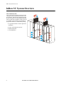
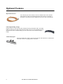
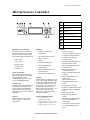
InfraStruXure™ InRow SC
Air-Cooled Self-Contained- 50/60Hz
Technical Data
Contents
Overview . . . . . . . . . . . . . . . . . . . . . . . . . . . . . . . . . . . . . . . . . . . . . . . . 1
InRow SC System Overview . . . . . . . . . . . . . . . . . . . . . . . . . . . . . . . . 2
Application Guidelines . . . . . . . . . . . . . . . . . . . . . . . . . . . . . . . . . . . . 3
Standard Features . . . . . . . . . . . . . . . . . . . . . . . . . . . . . . . . . . . . . . . . 4
Optional Features . . . . . . . . . . . . . . . . . . . . . . . . . . . . . . . . . . . . . . . . . 5
Microprocessor Controller . . . . . . . . . . . . . . . . . . . . . . . . . . . . . . . . . 6
Components . . . . . . . . . . . . . . . . . . . . . . . . . . . . . . . . . . . . . . . . . . . . . 7
Air-cooled Performance Specifications . . . . . . . . . . . . . . . . . . . . . . . 9
General Technical Specifications . . . . . . . . . . . . . . . . . . . . . . . . . . . 10
Electrical Data . . . . . . . . . . . . . . . . . . . . . . . . . . . . . . . . . . . . . . . . . . 11
Sound Performance Data . . . . . . . . . . . . . . . . . . . . . . . . . . . . . . . . . 12
Dimensional Data . . . . . . . . . . . . . . . . . . . . . . . . . . . . . . . . . . . . . . . . 13
Mechanical Connections . . . . . . . . . . . . . . . . . . . . . . . . . . . . . . . . . . 14
Guidelines for Installation . . . . . . . . . . . . . . . . . . . . . . . . . . . . . . . . . 15
Guide Specifications . . . . . . . . . . . . . . . . . . . . . . . . . . . . . . . . . . . . . 17
i
ii
Overview
The InRow SC offers efficient,
effective and economical cooling
for a variety of wiring closets and
server room spaces.
• Computer rooms
• Wiring Closets
• Telecommunication facilities
• Power equipment
• Medical equipment rooms
• LAN/WAN environments
A worldwide network of APC representatives is fully qualified to
provide engineering, sales, installation and service for our products.
APC warrants all parts for 12
months from date of shipment.
Extended warranties are available.
Capacity
The InRow SC self contained configuration is available in a nominal
capacity of 5kW with extended
capacity of up to 7kW when used in
conjunction with RACS (Rack Air
Containment System) or elevated
return temperatures.
In-row Advantages
The In-row solution improves
energy efficiency and cooling ability in a number of ways. First, the
room air is pulled in through a filter
at the rear of the unit, is cooled, and
is then distributed out the front of
the unit to cool the space. Air from
outside the room is utilized for
rejecting heat for cooling by the
building AC system. Removing and
neutralizing the heat from the hot
aisle provides for a more efficient
return air path than placing the air
conditioner along the perimeter.
The cold air is then supplied to the
area in front of the racks, exactly
where it is needed.
Regulatory Approvals
• CE Compliant
• UL Listed
• IEC Certified
• BSMI
• EN 55022 Class A
• FCC Part 15 Class A
• ICES-003
• VCCI
• VDE
Configuration
• Self Contained Air-cooled
Standard Features
• Variable Speed Direct Drive
Tubeaxial Fans
• Insulated Side Panels
• Evaporator Coil
• Condenser Coil
• Compressor
• Condensate Pump
• Condensate Pan
• Electronic Hot Gas Bypass
Valve
• Single Cord Power Supply
• Microprocessor Controller
• Network Management Card
• High Head Pressure Protection
• Rack Inlet Temperature
Control
• Remote Shutdown
• Dual Fan Power Supply
• Input/Output Contacts- Alarms
• Washable Filters
• Condenser Ducting Kit
• SX Rack Baying Kit
Optional Features
• Rope Water Detector
• Cable Support Bridge Trough
• VX Rack Baying Kit
APC InRow SC Technical Data Manual
1
InRow SC System Overview
InRow SC System Overview
Self Contained System
An air-cooled self-contained system has all the
refrigerant system components located in a single enclosure. The unit is pre-charged from the
factory and requires no field installed refrigerant
lines or remote heat exchangers. Heat is rejected
to a building return plenum via the ducting kit
designed to connect to a standard drop ceiling.
• No specialized skills or trades required for
installation
• Factory sealed and tested system
• Rapidly deployable
n a2 56 9a
• Low maintenance
2
APC InRow SC Technical Data Manual
Application Guidelines
Application Guidelines
Self-Contained System
The InfraStruXure InRow SC self-contained unit is designed to be placed in-row, between equipment racks for cooling-only applications. The unit has a nominal cooling capacity of 5kW and is intended to provide dedicated cooling
for wiring closets, server rooms and small data centers that have a drop ceiling as part of the building return plenum.
The unit is designed for very high sensible heat ratio cooling.
In order for the unit to operate properly, the following mechanical requirements must be met on a 24x7 basis:
• Provide at least 850 CFM (1440 m3/hr) of airflow to and from the condenser of each unit deployed
• Condenser inlet air temperatures must be between 32-105oF (0-40oC)
• Heat rejected by condenser, up to 10kW per unit, must be treated by the building cooling system
• Provide condensate drain connection
• Provide adequate clearances for airflow, maintenance service
The InRow SC is compatible with the Rack Air Containment System (RACS) and can be used to isolate the heat load
from individual racks. When combined with front and rear containment, the nominal cooling capacity is up to 7kW
for the 60 Hz unit (and up to 6.3kW for 50 Hz unit). Minimum load requirements must also be observed to prevent
the compressor from cycling off. If the compressor cycles off, there is a minimum off time period of 2-minutes where
no cooling is provided and the desired rack inlet temperatures may be exceeded. RACS is not designed to protect the
SC unit or IT equipment from harsh, corrosive or dirty environments.
• Minimum recommended heat load is 3kW per SC unit, depending on room conditions
• Configurations include rear containment only or front and rear containment
Further Reading
For additional guidance regarding the InRow SC refer to the following application notes and white papers:
3
• AN-90
Rack Air Containment Configurations for InRow Cooling Units
• AN-109
Application Guidelines for the InfraStruXure InRow SC Condenser
• AN-112
Best Practices for Deploying the InfraStruXure InRow SC
• AN-113
Configuration Types and Sequence of Operations for the InfraStruXure InRow SC
• AN-114
Guidelines for Using Rack Air Containment System with InfraStruXure InRow SC
• AN-115
UPS Power for the InfraStruXure InRow SC
• WP-68
Cooling Strategies for IT Wiring Closets and Small Rooms
• WP-130
The Advantages of Row and Rack-Oriented Cooling Architectures for Data Centers
APC InRow SC Technical Data Manual
Standard Features
Variable Speed
Direct Drive
Tubeaxial Fans
Each unit is
equipped with
six 200mm
mixed flow,
direct drive,
tubeaxial DC
fans. Three of the fans blow air
across the condenser coil to provide
heat rejection from the refrigerant
system. In order to provide uniform
airflow across the evaporator coil,
the remaining three fans draw air
through the evaporator section. The
evaporator fans can be easily
replaced while the unit is in operation. All fans are variable speed,
allowing them to assist in modulating unit cooling capacity and
maintaining refrigerant head
pressure.
Insulated Side Panels
The frame
is constructed of
16 gauge
formed
steel for
maximum strength. All exterior
panels and corner posts on the
frame are powder coated for durability and an attractive finish. Front
and rear exterior panels are constructed of 18 gauge perforated
steel with 69.5% open free area.
Insulation is 5 lb/ft3 (80.1 kg/m)
density and complies with ASTM
E84 rating of 25/50.
Condensate Pump
Removes condensate from the system to ensure continuous operation.
The factory installed and wired condensate pump is capable of
pumping 1.3g/hr (5.9l/hr) against
head pressures of up to 50ft (15.2m)
of total run, of that 16ft (4.9m) can
be vertical lift.
4
Condensate Pan
Condensate Pan is fabricated from
V-0 polymeric materials and is thermal formed, provided with
antifungal additives, and is a nonferrous material for higher indoor
air quality.
Electronic Hot Gas Bypass
An electronically controlled hot gas
bypass valve directs hot discharge
gas from the compressor back to the
expansion valve and into the coil.
During lightly loaded conditions,
compressor cycling is reduced and
prevents the evaporator coil from
freezing. Hot gas bypass also assists
in the management of the refrigerant head pressure.
Single Cord Power Supply
The 60hz unit utilize a NEMA L620 plug, the 50hz unit uses an IEC
309 16A plug. The power cord can
be connected to the power feed
either through the top or bottom of
the unit.
Network Management Card
Permits multi-level access to monitoring, control, and event
notification features over the user’s
network. Also allows the InRow SC
to be integrated into APC’s InfraStruXure Manager device.
High Head Pressure Protection
The condenser fans modulate to
maintain a nominal refrigerant discharge of 425 PSIG (6.9kPa). If the
condenser inlet air is restricted or
too warm, the refrigerant discharge
pressure will rise forcing the condenser fans to increase speed to
100%. To prevent a total loss of
cooling, the unit will slow evaporator fans and begin to activate the hot
gas bypass valve to reduce system
capacity. If the discharge pressure
continues to rise, the unit will shut
down in order to prevent unit
damage.
APC InRow SC Technical Data Manual
Rack Inlet Temperature Control
To control the unit based on rack
inlet temperature, a remote sensor is
provided. This sensor is factory
wired for a remote placement in the
field on adjacent IT racks.
Remote Shutdown/IO Contacts
The unit provides one field connection input for remote shutdown. I/O
contacts allow for remote annunciation of any alarm condition or
critical only alarms.
Dual Fan Power Supply
The unit includes 2 power supplies,
each capable of running all fans at
80% capacity in the event of a single power supply failure. Individual
power supplies are hot swappable.
Washable Filters
The filtration of conditioned air is
extremely vital to maintaining the
clean, particle-free environment
required by electrical equipment.
Filters are <20% efficient
(ASHRAE 52.1) and MERV 1
(ASHRAE 52.2) rated that meets
HF-1 standards for electronics.
Ducting Kit w/Ceiling Adapter
60Hz units have a 24in x 24in
adapter, 50Hz units have a
600mm x 600mm adapter. Each
duct tube is 6 ft. (1.8m) long and
10in (254mm) in diameter. Three
ducts are provided, one for the condenser supply and two for the
condenser exhaust. Mounting hardware is provided to attach ducts to
the ceiling adapter.
SX Rack Baying Kit
Baying kit enables the cooling system to be bayed to the APC
Netshelter SX enclosures. Kit is
made of 16 gauge steel.
Optional Features
Rope Water Detectors
The solid-state spot water detector activates an audible alarm on the controller
when moisture is detected, providing protection along a 20ft (6.1m) length. A
maximum of four detectors can be installed in series, for a total of 80ft (24.4m).
Cable Support Bridge Trough
Organizes cables over the top of the unit without interfering with the duct tubes. The bridge
trough is mounted to the racks, which allows the InRow SC to be moved without having to
disconnect any of the overhead cabling. Up to 80 CAT5 cables can fit inside the bridge
trough.
VX Rack Baying Kit
Baying kit enables the cooling system to be bayed to the APC Netshelter VX Rack Enclosures. Kit is made of 16 gauge powder coated steel.
5
APC InRow SC Technical Data Manual
Microprocessor Controller
Microprocessor Controller
X
Y
Z
[
\
]
^
_
`
Microprocessor Controller
The microprocessor controller is
standard on each system. The controller provides precision control
for the demanding requirements of:
• Data centers
• Server rooms
• Wiring closets
• Switch rooms
• UPS rooms
Open Architecture
The NetworkAIR SC protocol is
open for integration with all building management systems.
Communication interface on the
system is MODBUS RS485.
Control Type
Controller utilizes proportional and
integral derivative (PID), a time
proven precision environmental
control method. The PID is nonadjustable, and can not be customer
configured.
Control
The backlit, four-line by twenty
character display is password
configurable.
Functions
• Supply and Return Air
Temperatures
• Operational Mode Control
• Event Logging
• Alarms
• Fan Speed Adjustment
• Input/Output Module
Programming
• Refrigerant Discharge and
Suction Pressure
• Suction Line Temperature
Logging
The microprocessor displays the 30
most recent alarms. Each alarm log
contains a time/date stamp as well
as operating conditions at the time
of occurrence. The controller also
displays run time, in hours, for
major components (Air Filter, Condenser Fans, Evaporator Fans,
Compressor, Condensate Pump,
Fan Power Supplies).
Factory Default Set Points:
•
•
•
•
•
Cool: 72.0°F (22.2°C)
Deadband: 1.8°F (1.0°C)
Supply Air InRow: 64.0°F (17.8°C)
Supply Air RACS: 64.0°F (17.8°C)
Supply Air Spot: 57.0°F (13.9°C)
APC InRow SC Technical Data Manual
Critical Alarm LED
Warning Alarm LED
Check Log LED
Status LED
Liquid Crystal Display (LCD)
Up and Down Arrow Keys
ESC key
Enter key
Help key
Alarms
• Air Filter Clogged
• Air Filter Run Hours Violation
• Condensate Pump Full Fault
• Condenser Fan #n Fault
• Cooling Failure
• Persistent High Discharge/Low
Suction Pressure Alarm
• Rack Inlet High Temperature
Violation/Fault
• Suction Pressure Sensor/
Temperature Fault
• Supply Air High Temperature
Violation
• Upper Return/Supply Air
Sensor Fault
• Water Detection Fault
• Discharge Pressure Sensor
Fault
• Evaporator Fan #n Fault
• External Communication Fault
• Fan Power Supply Left/Right
Fault
• Filter Sensor Fault
• High Discharge Pressure
Alarm
• Internal Communication Fault
• Lower Return/Supply Air
Sensor Fault
• Low Suction Pressure Alarm
• On Standby: Input Contact
Fault
6
Components
na2229a
External View
Intake Air Duct
Adjustable Leveling Foot (4 places)
Removable Rear Door
Display Interface
Side Panel Latch/Lock
Removable Front Door
Removable Side Panel
Door Lock
Rear Casters (Non-swiveling)
Exhaust Air Duct
Front Casters (Swiveling)
APC InRow SC Technical Data Manual
7
Components
na2219a
Internal View
Condenser Coil
Refrigeration Filter Drier
Condenser Fans
Hot Gas Bypass Valve
Compressor
Power Supply
Condensate Pan Floats
Condensate Pump
Evaporator Fans
High Voltage Box
Evaporator Coil
Thermostatic Expansion Valve
8
Washable 1/2in Air Filter
! User Interface Box
APC InRow SC Technical Data Manual
Air-cooled Performance Specifications
NET COOLING CAPACITY
Model
ACSC100
ACSC101
200-240V, 1ph, 60Hz
200-240V, 1ph, 50Hz
Total - BTU/hr (Watts)
16300 (4770)
15100 (4410)
Sensible - BTU/hr (Watts)
15100 (4440)
14300 (4200)
Total - BTU/hr (Watts)
17000 (4980)
15400 (4510)
Sensible - BTU/hr (Watts)
15500 (4530)
14400 (4230)
Total - BTU/hr (Watts)
16700 (4890)
16200 (4740)
Sensible - BTU/hr (Watts)
16200 (4740)
15900 (4650)
Total - BTU/hr (Watts)
18100 (5310)
18000 (5250)
Sensible - BTU/hr (Watts)
15500 (4560)
16000 (4680)
Total - BTU/hr (Watts)
17200 (5040)
16700 (4890)
Sensible - BTU/hr (Watts)
17200 (5040)
16700 (4890)
Total - BTU/hr (Watts)
18000 (5250)
16700 (4890)
Sensible - BTU/hr (Watts)
18000 (5250)
16700 (4890)
Total - BTU/hr (Watts)
22000 (6450)
21300 (6240)
Sensible - BTU/hr (Watts)
11300 (3300)
11300 (3300)
Total - BTU/hr (Watts)
22200 (6500)
19800 (5800)
Sensible - BTU/hr (Watts)
22200 (6500)
19800 (5800)
ELECTRICAL INPUT
70°F DB, 58.5°F WB (21.1°C DB, 14.7°C WB)
72°F DB, 60.0°F WB (22.2°C DB, 15.6°C WB)
75°F DB, 61.0°F WB (23.9°C DB, 16.1°C WB)
80°F DB, 67.0°F WB (26.7°C DB, 19.4°C WB)
80°F DB, 62.5°F WB (26.7°C DB, 16.9°C WB)
85°F DB, 65.0°F WB (29.4°C DB, 18.3°C WB)*
95°F DB, 82.7°F WB (35.0°C DB, 28.2°C WB)**
96°F DB, 68°F WB (35.5°C DB, 20°C WB)***
Note: All values are accurate to +/- 5% and based on full fan speed with standard filters and 95oF (35oC) Condenser entering air
All tests were performed at 100% evaporator fan speed except as noted. Net cooling data is published above.
*Airflow reduced to 1000 CFM (1700 m3/hr) at this condition to maintain appropriate suction temperature
**Airflow reduced to 600 CFM (1020 m3/hr) at this condition to maintain appropriate suction temperature
***Airflow reduced to 850 CFM (1440 m3/hr) to maintain appropriate suction temperature. Represents conditions with front and
rear containment
Altitude Correction Factors for InRow Products
Altitude (ft)
0
1000
2000
3000
4000
5000
6000
7000
8000
9000
10000
Specific
Volume
13.58
14.09
14.62
15.18
15.76
16.36
17.00
17.67
18.37
19.11
19.89
Density lb/ft3
0.074
0.071
0.068
0.066
0.063
0.061
0.059
0.057
0.054
0.052
0.050
Density Ratio
1.000
0.964
0.929
0.895
0.862
0.830
0.799
0.769
0.739
0.711
0.683
Capacity
Correction
1.00
0.981
0.962
0.933
0.913
0.884
0.865
0.846
0.826
0.807
0.787
Note: Room condition 72oF db/50% RH.
Density ratio is used for air flow correction factor. Capacity correction is used for performance derate
9
APC InRow SC Technical Data Manual
General Technical Specifications
MODEL
ELECTRICAL INPUT
AIR SYSTEM - Direct Drive Tubeaxial Fans*
Maximum Evaporator Airflow - CFM (m3/hr)
Minimum Evaporator Airflow - CFM (m3/hr)
Maximum Condenser Airflow - CFM (m3/hr)
Minimum Condenser Airflow - CFM (m3/hr)
REFRIGERANT
R410A - oz (kg)
Maximum Total Heat of Rejection BTU/hr (Watts)
EVAPORATOR COIL - COPPER TUBE/ALUMINUM FIN
ACSC100
ACSC101
200-240V, 1ph, 60Hz 200-240V, 1ph, 50Hz
Face Area - ft2 (m2)
Rows Deep
Face Velocity - FPM (m/s)
FILTERS
Quantity
Size - in (mm)
Depth - in (mm)
Efficiency- ASHRAE 52.1 (ASHRAE 52.2)
PHYSCIAL DATA - UNIT
Weight - lbs (kg)
Height - in (mm)
Width - in (mm)
Depth - in (mm)
PHYSICAL DATA - CONDENSER DUCT TUBES
Length - ft (m)
Diameter - in (mm)
CONNECTION SIZES - CONDENSATE DRAIN
Drain Line ID - in (mm)
Note: *Airflow automatically varies depending upon operating conditions
APC InRow SC Technical Data Manual
1200 (2038)
400 (679)
850 (1440)
300 (509)
52 (1.47)
34000 (10000)
29700 (8700)
2.5 (0.23)
2
380 (2.44)
1
9.375 X 36.75 (238 X 933)
1/2 (13)
<20% (MERV 1)
365 (165.9)
78.4 (1991)
11.8 (300)
42.1 (1069)
6 (1.8)
10 (254)
3/16 (4.76)
10
Electrical Data
Electrical Data
Rated
SKU
In-Rush***
Phase
Frequency
(Hz)
Current*
(Amps)
Power**
(Watts)
Power
Factor
Duration
(ms)
Peak
Current
(Amps)
Power
(Watts)
208-230
1
60
16.0
2940
0.98
200
56.0
8240
220-240
1
50
14.4
2390
0.98
60
65.0
10100
Voltage
(Volts)
ACSC100
ACSC101
Plug
Type
Note: *Rated Current is the maximum current draw for the input voltage range
**Rated Power is maximum power consumption expected during normal operations, actual power draw may vary based upon operating conditions
***In-Rush is of short duration and only occurs during start-up and compressor cycling.
APC InRow SC Technical Data Manual
11
Sound Performance Data
Sound Performance Data
Air-Cooled Tested Sound Data
Fan Speed%
Evaporator
Air-flow
Rate
(SCFM)
Octave Band Hz, Sound Power dB re 10-12Watts.
Data obtained from Reverberation Sound Tests in
accordance with ANSI S12.51-2202, ISO 3741-1999
125
250
500
1000
2000
4000
8000
Sound
Power
(dBA)
Lp Sound
Pressure dB
re: 20
microPa*
dBA
EvF 100%
CondF 100%
1180
77.5
86.5
86.5
83.0
78.0
75.5
70.5
87.7
82.2
EvF 90%
CondF 100%
1080
77.5
86.5
85.5
81.0
76.0
73.5
68.0
86.4
81.0
EvF 80%
CondF 100%
960
82.0
86.5
85.5
79.5
75.5
70.5
65.5
85.7
80.5
EvF 60%
CondF 80%
810
74.5
87.0
79.5
78.5
73.0
66.5
62.5
83.9
78.1
Note: Abbreviations EvF and CondF stand for evaporator fan and condenser fan respectively
*Weighted Sound Pressure dBA in a 10ft x 10ft x 10ft room at 5 ft distance
Sound data verified by testing at NRTL
12
APC InRow SC Technical Data Manual
Dimensional Data
na2231a
InRow SC Assembled Module
Dimensions are inches (millimeters)
APC InRow SC Technical Data Manual
13
Mechanical Connections
Mechanical Connections
InRow SC Condensate Line and Power Connections
Dimensions are inches (millimeters)
Note: For more detailed information, please refer to submittal drawings
14
APC InRow SC Technical Data Manual
Guidelines for Installation
The InRow SC provides reliable, self-contained cooling that maximizes availability within small IT rooms
and wiring closets. The unit incorporates the latest system design innovations to provide you with
optimum efficiency, reliability and rapid installation.
For more detailed information, see the InRow SC Installation manual (990-2796).
For locations with seismic installation requirements, additional information regarding anchorage
selection is provided in the InRow SC Seismic Installation Manual addendum (990-3063).
Room preparation
During the design of the data center, consider ease of entry for the equipment, floor loading factors,
and accessibility to ducting and wiring.
Ensure the room is insulated to minimize the influence of exterior heat loads. Use the minimum
required amount of fresh air for make up to comply with local and national codes and regulations.
The room must be sealed with a vapor barrier to minimize migration of moisture. Polyethylene film
(plastic sheeting) is a good vapor barrier for ceiling and wall applications. Rubber, or plastic-based
paints, should be applied to concrete floors and walls. The room should be thoroughly insulated to
minimize thermal loads and make-up air (if required) should be pre-conditioned to reduce additional
temperature, filtration, and moisture loads.
The room should have a drop ceiling that is part of the building HVAC system. The plenum should be
at least 12in (300mm) deep and provide adequate airflow for each unit supported. The HVAC system
must be capable of rejecting up to 34000 BTU/hr (10kW) of heat per unit. Refer to Application Note
AN-109 and the InRow SC Installation manual for additional information.
Receiving the unit
Your InRow SC unit has been factory tested and inspected prior to shipment. To ensure that you have
received the unit in excellent condition, perform a careful inspection of the crating and the unit
immediately upon receipt. Verify that all parts ordered were received. Report any damage discovered
to the freight carrier. If necessary, contact the APC technical service department at 1-888-695-6500
for help in repairing or replacing damaged parts. While APC is not responsible for damage incurred
in transit, we want to make sure that you have no undue delays in your system start-up.
Rigging
The unit is manufactured with a formed steel frame for maximum strength and unit integrity.
However, as with all electrical and mechanical equipment, you must take care with proper rigging of
your unit. The equipment is easily tipped over. Use extreme caution when unpacking and moving.
When using a forklift, move the unit on the shipping pallet only. When moving the equipment on a
ramp, always point the narrow width in the direction of travel. Do not place the equipment on its side.
If the equipment has been tilted, place it upright on a flat, solid surface and keep in this position for at
least 24 hours before operating. For more detailed information, refer to the APC Receiving and
Unpacking manual (990-2795A).
APC InRow SC Technical Data Manual
15
Guidelines for Installation
Service Access
n a2 23 0 a
Routine service and basic repair activities can be accomplished with front and rear access only. APC
recommends 36ft (914mm) of clear floor space in front and back of the unit for this purpose. For major
repair activities needing side access, 30ft (762mm) of clear space should be provided as needed. At least
42ft (1070mm) of clear space is required to free the unit from the row of rack enclosures.
Dimensions are inches (millimeters)
16
APC InRow SC Technical Data Manual
Guide Specifications
Standard Components
A. CABINET CONSTRUCTION
1 . Exterior panels shall be 18 gauge metal with 5 lb/ft3 (80 kg/m3) density foam insulation.
Insulation complies with UL94-5VA ASTM E84 flame spread and smoke developed
rating of 25/50. Front and rear exterior panels shall be 18 gauge perforated steel with
69.5% open free area, and equipped with a keyed lock to provide a means of securing
access to the internal components of the unit.
2 . The frame shall be constructed of 16 gauge formed steel welded for maximum strength.
All units shall provide full service from the front and rear, allowing units to be placed
within a row of racks.
3 . All exterior panels and frame shall be powder coated for durability and attractive finish.
Exterior frame and panel color shall have color values: L = 74.50, a = -.53, b = +8.20.
4 . Units shall include casters and leveling feet to allow ease of installation in the row and
provide a means to level the equipment with adjacent IT racks.
B. VARIABLE SPEED DIRECT DRIVE MIXED FLOW DC FAN ASSEMBLY
1 . Fan: The unit shall be configured for draw-through air pattern to provide uniform air flow
over the entire face of the coil. Each unit shall include six 200 mm mixed flow direct drive
DC axial fans. Three fan assemblies shall be designed to provide 400 CFM (680 m3/hr)
each across the evaporator coil for total unit airflow of 1200 CFM (2039 m3/hr). Three fan
assemblies shall be designed to provide 283 CFM (480 m3/hr) each across the condenser
coil for total unit airflow of 850 CFM (1440 m3/hr).
2 . Variable Speed Fans: Fans shall be variable speed capable of modulating from 30-100%.
Fans shall soft start to minimize in-rush current when starting.
3 . Fan Protection: Each evaporator fan assembly shall consist of a plastic injection molded
bezel with integral fan discharge finger guard. Inlet of the fan should include a cage type
finger guard.
4 . Operation and Service: The unit should be capable of operation in the event of a fan
failure. Evaporator fans shall be replaceable while the unit is in operation.
C. POWER SUPPLY
1 . Input Power Feed: Single power input should be a locking NEMA or IEC plug connection
suitable for the input power selected. Unit power consumption is not to exceed 2950 watts
during normal operation.
2 . Fan Power Supplies: Dual internal DC power supplies are capable of running all fans at
80% capacity in the event of a power supply failure. Power supplies shall be hotswappable.
APC InRow SC Technical Data Manual
17
Guide Specifications
D. MICROPROCESSOR CONTROLLER
1 . Monitoring and Configuration: The master display shall allow monitoring and
configuration of the air conditioning unit through a menu-based control. Functions include
status reporting, set-up, and temperature set points. Four LEDs report the operational
status of the connected air conditioning unit.
2 . Controls: The microprocessor controller shall come equipped with control keys to allow
the user to navigate between menus, select items, and input alpha numeric information.
3 . Alarms: The microprocessor controller shall activate a visible and audible alarm in the
occurrence of the following events:
a. Air Containment Pressure Sensor Fault
b. Air Filter Clogged
c. Air Filter Run Hours Violation
d. Condensate Pan Full Fault
e. Condensate Pump Fault
f. Condenser Fan #n Fault
g. Cooling Failure
h. Discharge Pressure Sensor Fault
i. Evaporator Fan #n Fault
j. External Communication Fault
k. Fan Power Supply Left Fault
l. Fan Power Supply Right Fault
m. Filter Sensor Fault
n. High Discharge Pressure Alarm
o. Internal Communication Fault
p. Lower Return Air Sensor Fault
q. Lower Supply Air Sensor Fault
r. Low Suction Pressure Alarm
s. On Standby: Input Contact Fault
t. Persistent High Discharge Pressure Alarm
u. Persistent Low Suction Pressure Alarm
v. Rack Inlet High Temperature Violation
w. Rack Inlet Temperature Sensor Fault
x. Return Air High Temperature Violation
y. Suction Pressure Sensor Fault
z. Suction Temperature Sensor Fault
aa. Supply Air High Temperature Violation
ab. Upper Return Air Sensor Fault
ac. Upper Supply Air Sensor Fault
ad. Water Detection Fault
18
APC InRow SC Technical Data Manual
Guide Specifications
4 . Logging: The microprocessor controller shall log and display all available events. Each
alarm log shall contain time/date stamp as well as operating conditions at the time of
occurrence. Controller shall display the run time hours for major components.
E. NETWORK MANAGEMENT CARD
The unit shall include a network management card to provide management through a computer network through TCP/IP. Management through the network should include the ability to change set points as well as view and clear alarms.
F. EVAPORATOR AND CONDENSER COIL
Coil shall use raised lance with rippled edge type aluminum fin and 0.375in OD rifled
copper tube coils with 0.012in wall thickness. Coil end supports shall be a minimum 18
gauge G90 galvanized steel.
G. CONDENSATE PAN
Drain pan shall include a condensate pump and dual floats for control and overflow protection. Condensate pans are V-0 thermal formed, anti-fungal, non-ferrous material for
higher indoor air quality.
H. CONDENSATE PUMP
Factory installed and wired condensate pump shall pump 1.3 gal/h (4.9 liters/hour) at 16ft
(4.9m) of vertical lift and a 50ft (15.2m) horizontal run.
I.
FILTERS
Standard air filter: <20% efficient per ASHRAE 52.1, MERV 1 per ASHRAE 52.2, 1/2in
washable mesh filter.
J.
REMOTE TEMPERATURE SENSOR
Remote temperature sensor shall be shipped factory wired to the unit for placement in the
field to provide control input based on rack inlet temperature. Length is 14ft.
K. HOT GAS BYPASS
The unit shall use an electronic stepper valve for hot gas bypass operation. The actuator
will have 1596 steps from fully open to fully closed. The discharge gas will be piped to the
unit thermostatic expansion valve.
L. DUCTING KIT
Ducting kit with ceiling tile adapter is included with the unit. Duct tubes shall be 10in
(254mm) in diameter and 6ft (1.8m) long and constructed from UL 181 Class I material.
APC InRow SC Technical Data Manual
19
Guide Specifications
Ceiling tile adapter shall be suitable for either 24in x 24in or 600mm x 600mm suspended
ceiling grids and constructed of powder coated metal.
M. CABLE WATER DETECTORS (OPTIONAL)
1 . A leak detection sensing cable shall be shipped loose with the unit. If water or other
conductive liquids contact the cable anywhere along its length, the main controller
visually and audibly annunciates an alarm.
2 . The detector shall be provided with a 20ft (6.1m) of cable. Additional cable may be
cascaded up to 80ft (24.4m) total length. A total of four water detectors are available per
unit.
N. CABLE SUPPORT BRIDGE TROUGH (OPTIONAL)
Overhead cable distribution bridge shall connect to adjacent racks and allow for removal
of the unit without disrupting the cable connections. The trough shall be made of 16 gauge
metal with powder coat finish. Trough shall be capable of carrying no less than 80 CAT5
cables.
20
APC InRow SC Technical Data Manual
®
APC Worldwide Customer Support
Customer support for this or any other APC product is available at no charge in any of the following ways:
• Visit the APC Web site to find answers to frequently asked questions (FAQs), to access documents
in the APC Knowledge Base, and to submit customer support requests.
– www.apc.com (Corporate Headquarters)
Connect to localized APC Web sites for specific countries, each of which provides customer
support information.
– www.apc.com/support/
Global support with FAQs, knowledge base, and e-support.
• Contact an APC Customer Support center by telephone or e-mail.
– Regional centers:
APC headquarters U.S.,
Canada
(1)(800)800-4272 (toll free)
Latin America
(1)(401)789-5735 (USA)
Europe, Middle East, Africa
(353)(91)702020 (Ireland)
Asia Pacific
(61) 2 9955 9366 (Australia)
– Local, country-specific centers: go to www.apc.com/support/contact for contact information.
Contact the APC representative or other distributor from whom you purchased your APC product for
information on how to obtain local customer support.
Entire contents copyright © 2007 American Power Conversion. All rights reserved.
Reproduction in whole or in part without permission is prohibited. APC, the APC logo, and
NetworkAIR are trademarks of American Power Conversion Corporation and may be
registered in some jurisdictions. All other trademarks, product names, and corporate names
are the property of their respective owners and are used for informational purposes only.
990-8700-001
02/2007