1
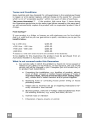
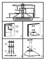
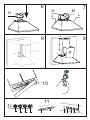
Instructions Manual
CWB 6441 - CWB 9441
INDEX
EN
WARNINGS - COMPONENTS .............................................................................................................................................. 3
INSTALLATION...................................................................................................................................................................... 4
USE - MAINTENANCE .......................................................................................................................................................... 5
2
2
WARNINGS - COMPONENTS
WARNINGS
This appliance has been designed for use as either an EXTRACTION (ducting to the outside)
or RECIRCULATION (filtering) hood. The measurements contained on the drawings in this
booklet refer to two models of cooker hood. Therefore, it is essential that you refer to the correct drawing when taking measurements for installation.
- The minimum distance between the cooking surface and the metal grease filters on the
underside of the hood must be 650mm.
- This cooker hood must be installed in accordance with the installation instructions and
all requirements must be adhered to.
- If the room where the cooker hood is to be used contains a fuel burning appliance such
as a central heating boiler then its flue must be of the room sealed or balance flue type.
- If other types of flue or appliances are fitted ensure that there is an adequate supply of
air to the room.
- When the range hood and appliance supplied with energy other than electricity are
simultaneously in operation, the negative pressure in the room must not exceed 4 Pa
(4x10⁻⁵ bar).
- The ducting system for this appliance must not be connected to any ventilation system
which is being used for any other purpose.
- The ducting system for this appliance must not be connected to any existing ventilation
system which is being used for any other purpose.
- Do not leave naked flames or carry out flambè cooking under this cooker hood.
- This appliance is not intended for use by persons (including children) with reduced
physical, sensory or mental capabilities, or lack of experience and knowledge, unless
they have been given supervision or instruction concerning use of the appliance by a
person responsible for their safety.
- Children should be supervised to ensure that they do not play with the appliance
CONNECTING THE POWER CABLE TO THE MAINS POWER SUPPLY
Before installation, check that the mains voltage indicated on the rating plate inside the appliance corresponds to the voltage available in your home. If the Hood is not fitted with a plug
have a licensed electrician, fit the power cable with a plug of a type approved for the load indicated on the rating plate; when connecting directly to the mains, insert an omni polar circuit
breaker with a minimum contact aperture of 3mm and a size suitable for the load in question
between the appliance and the mains supply, making sure it is of a type that complies with current regulations.
COMPONENTS
- 2 No Wall Brackets C
- 1 No 150-120mm Ducting Spigot G
- 1 No Air Outlet Connection H (Optional)
- 2 No Charcoal Filters L (Optional)
EN
3
3
INSTALLATION
The cooker hood must be installed centrally over a cooking appliance. The minimum distance
between the cooking surface and the metal grease filters on the underside of the hood must be
at least 650mm.
To install the hood proceed as follows:
1) Drill six 8mm diameter holes at X1-X2-J and insert the plastic rawl plugs supplied as illustrated in fig. 2 ensuring the brackets are fitted as shown in the blow up.
2) Secure the two brackets C to the wall inserting two of the screws supplied through the two
holes on line X1-X2 as illustrated in fig. 2.
3) Slide the canopy down the wall to locate the key hole over the washer then secure the canopy to the wall by inserting two of the screws supplied through the two outer holes in the
rim of the canopy J1 and J2 as illustrated in fig. 3.
4) EXTRACTION OR RECIRCULATION INSTALLATION:
• EXTRACTION (DUCTED)
When installing the ducted version, connect the hood to the chimney using either a flexible or
rigid pipe ø 150 or 120 mm, the choice of which is left to the installer.
• To install a ø 120 mm air exhaust connection, insert the reducer flange 9 on the hood body
outlet.
• Fix the pipe in position using sufficient pipe clamps (not supplied).
• Remove any activated charcoal filters.
• RECIRCULATION (FILTERED)
• When the hood is fitted in the recirculation mode the Air Outlet Connection H should be
fitted as illustrated in fig. 6.
• Fit the (optional) charcoal filters by repeating the following operation on each side of the
motor housing. Place the two key hole slots in the filter L and turn the filter clockwise to
lock the filter in position as illustrated in fig. 7.
WARNING: It is a possible fire hazard if the metal grease filters are not cleaned and the
charcoal filters replaced regularly.
Fitting The Chimney
5) FITTING THE CHIMNEY UPPER
To fit the upper chimney A, place the top edge of the chimney over the bracket C as illustrated in fig. 8 and secure the chimney using two of the 2.9mm self tapping screws provided.
The distance H in the height between the fixing holes X1 and X2 is determined by the
height of the upper chimney A.
6) FITTING THE CHIMNEY LOWER
To fit the lower chimney B, apply slight force to the two rear edges to increase the width
of the apperture, then sleeve the chimney B over the chimney A as illustrated in fig. 9.
EN
4
4
USE - MAINTENANCE
USE
The cooker hood functions are controlled by a series of slider or push button switches mounted
on the front of the hood and control the worktop lighting and fan motor speeds. This cooker
hood will not remove steam.
1) SLIDER SWITCHES
- A switch controls the worktop lighting - ON/OFF.
- A switch controls the fan speeds - OFF/ON-1-2-3.
- The red neon lamp illuminates when the motor is switched ON .
2) PUSH BUTTON SWITCHES
- A switch controls the worktop lighting - ON/OFF.
- A button switches the motor OFF/ON at the low speed setting.
- A button switches the motor to the medium speed setting.
- A button switches the motor to the high speed setting.
- The red neon lamp illuminates when the motor is switched ON.
3) SPEED SETTINGS
- 1/Low should be selected when simmering or when using only one pan.
- 2/Medium should be selected for cooking when using up to four pans.
- 3/High should be selected when frying or cooking food with a strong odour.
MAINTENANCE
N.B. Before carring out any kind of maintenance, cleaning or replacing lamps, disconnect the
hood from the mains supply.
1. Lighting
Comprises two (28W - 40W) bulbs. To replace the bulbs, proceed as follows (fig.10): Remove one of the pins at the sides of the lamp cover. Slide the glass towards the side from
which the pin has been removed until the opposite edge has been freed, then pull gently
downwards. Replace the bults and fit the glass again by repeating the above operations in
reverse order.
2. Filters
- The metal grease filter should be cleaned every two months or more frequently if the hood
is used consistently and can be cleaned in a dishwasher or by hand using a mild detergent
or liquid soap. When replacing, ensure that they are dry.
- The charcoal filter cannot be washed and should be replaced at least every 2 months or
more frequently if the hood is used consistently.
3. Cleaning
When cleaning the hood, it is recommended to use a damp cloth and mild liquid household
cleaner. Never use abrasive cleaning materials.
IMPORTANT: When using a gas hob in connection with the cooker hood never leave the
burners of the hob uncovered while the hood is in use or when the pans have been removed. It is very important to follow all instructions for cleaning the hood and filters.
There could be a possible fire hazard if the filters are not replaced according to these instructions.
ATTENTION: The manufacturer declines all responsibility for any damage or injury
caused as a result of not following the instructions for installation, for maintenance and replacement times of filters indicated (in order to avoid a possible risk of fire when the filters
are saturated with grease).
EN
5
5
EN
6
6
EN
7
7
EN
8
8
EN
9
9
X1
= =
15
H
X2
J
180
750 min
1140 max
A
= =
B
180
590 min
= =
180
275
290
600
700
900
1
X
X1
H
J
C
X2
1
2
J
1
2
3
2
C
G
J
4
5
6
H
L
H
7
M
L
9
8
B
10
11
L
2 3
0 1
1
0 1
T1
T2
T3
L
-
0
M
MID
MAX
L
S
V1
V2
V3
0-1
436005827_ver1