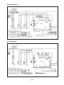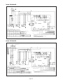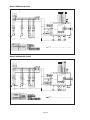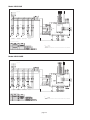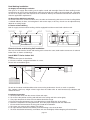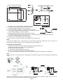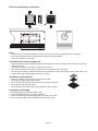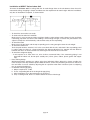
1
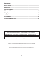
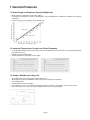
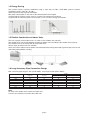
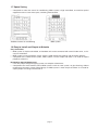
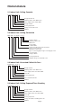
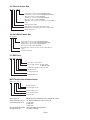
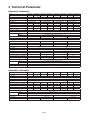
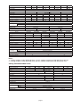
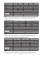
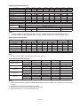
Engineered for flexibility and performance.
MULTI-DIGITAL SCROLL UNITS
MDS030A(R)~MDS60A(R)
MDS080B(R)~MDS300B(R)
page 2
TM
TM-MDS-2006
Contents
General Features ............................................................................................................. 2
Nomenclature................................................................................................................... 4
Technical Parameter ........................................................................................................ 7
Outlines and Dimensions ............................................................................................. 11
Wiring Diagrams ............................................................................................................ 16
Installation...................................................................................................................... 30
Troubleshooting............................................................................................................. 41
Servicing and Maintenance .......................................................................................... 42
Note: Installation and maintenance are to be performed only by qualified personal who are
familiar with local codes and regulations, and experienced with this type of equipment.
Caution: Sharp edges and coil surfaces are a potential injury hazard. Avoid contact with them.
Warning: Moving machinery and electrical power hazards. May cause severe personal injury or death.
Disconnect and lock off power before servicing equipment.
“McQuay” is a registered trademark of McQuay International. All rights reserved throughout the world.
2003 McQuay International
“Bulletin illustrations cover the general appearance of McQuay International products at the time of publication
and we reserve the right to make changes in design and construction at any time without notice.”
page 1
1 General Features
1.1 Wide Range and Stepless Capacity Modulation
•
•
Running ration of compressors %
•
Wide capacity modulation range (10%-100%)
According to changing the ralio of “loading time” and “unloading time”. MDS can modulate the capacity
steplessly.
Lower the energy consumption and running cosl.
MDS system
Inverter system
Total capacity of operating indoor units
1.2 Accurate Temperature Control and Quick Response
•
The cooling/heating capacity of the indoor units is controlled by the EXV. which ensures the low theperature
fluctuation of 0.3 C.
Stepless capacity modulation.
Ouick response to output the capcity (40s).
O
•
•
Temp.
The temperature fluctuation range of traditional system is ±2°C
Temp.
The temperature fluctuation range of MDS system is ±0.3°C
The temperature fluctuation range of traditional system is ±0.5°C
The temperature fluctuation range of MDS system is ±0.3°C
Time
Time
1.3 Simple, Reliable and Long Life
•
•
•
•
•
•
The PWM valve has the longevity of 40 million times.
Wide rage of capacity modulation makes sure the start/stop times reduces.
Less components.
No complicate inverter controller.
The compress or has an excellent oil return performance, there is no need for the oil return circuit.
Even the units run in 10% part load, the MDS system can be in good stage.
System control
Environment
Solenoid valve
Digital scroll
page 2
1.4 Energy Saving
The inverter system’s capacity modulation range is from 30% to 100%, while MDS system’s capacity
modulation range is from 10% to 100%.
Quick response to the capacity modulation.
Min. power consumption is only 10% of the full load power consumption.
Compared to the inverter system, there is no power consumption of transducer.
Compared to the nominal capacity scroll system, it can save 20% energy consumption.
10HP system
EER
100%
Digital
compressor
operating
Fixed
compressor
100% operating
10%
Traditional air
Traditional inverter
conditioning system
system
MDS system
Heavy loading
Load
Light loading
1.5 Flexible Combination of Indoor Units
The max. capacity of the indoor units is as 130% as the outdoor units capacity.
The outdoor units can connect different numbers of indoor units according to the outdoor units capacity.
One outdoor unit can be connected up to 48 indoor units.
Various types of indoor units are available.
There are various indoor units for option: concealed exposed, ceiling concealed, high static pressure fan coil
and ceiling exposed/floor standing.
1.6 Long Accessory Pipe Connection Design
Max. accessory pipe length is 15m (12HP-30HP), max. height is 50m (8HP—30HP).
Height
Max. accessory pipe total
length (m)
Max. accessory pipe
length (m)
OT
IT
12-30HP
350
150
50
40
10HP
250
125
50
40
8HP
250
125
50
40
6HP
150
70
30
30
5HP
150
70
30
30
4HP
150
70
20
20
3HP
100
50
20
20
Note:
OT means the outdoor unit is above the indoor unit,
IT means the outdoor unit is below the indoor unit.
page 3
1.7 Space Saving
•
Compared to scale size central air conditioning, MDS system is high centralized, no need for special
equipment room to save more space, and bring more benefits.
Traditional central air conditioning
MDS system
1.8 Easy to Install and Simple to Maintain
Easy Installation
• MDS system is simple and reliable, and outdoor unit can be connected with several indoor units, so it is
easy for installation.
• MDS system can be installed by stages, which is good to both new projects and renovation projects.
• Compared to the chilled water system, MDS system is much simple and there is no need for expert
people to maintain it.
No Need for Special Maintenance
• It has only simple refrigerant piping system, no complex maintenance;
• Compared to the water-cooled system, MDS system is with no water system, no pipe cleaning, without
maintenance for water system control design; so MDS system is much simple and there is no need for
expert people to manage and maintain it.
page 4
Nomenclature
2.1 Indoor Unit: Ceiling Cassette
M CK 030 T -A M A
Design alteration No
Matching outdoor units: MDS series
Power supply feature: 220V~/50Hz
Design serial No.
Cooling capacity No.
Ceiling cassette indoor unit
McQuay
2.2 Indoor Unit: Ceiling Concealed
MCC 050 T -R (B)/(D) -A M A
Design serial No
Matching outdoor units:
MDS series
Power supply:
A: 220V~/50Hz
Return air mode: B-rear return air plenum
D-lower return air plenum
Omitted-no return air box
Type of connecting pipe: R- right connecting pipe L-left
connecting pipe
Design serial No.
Cooling capacity No.
McQuay ceiling concealed indoor unit
2.3 Indoor Unit: Air-cooled Chilled Air Duct
M DB 050 T -A M A
Design serial No.
Matching outdoor units: MDS series
Power supply feature: A is 220V~/50Hz
Series No.
Cooling capacity No.
Air-cooled chilled air duct
McQuay
2.4 Indoor Unit: Ceiling Exposed/Floor Standing
M CM 050 T -A M A
Design serial No.
Matching outdoor units: MDS series
Power supply feature: A is 220V~/50Hz
Series No.
Cooling capacity No.
Ceiling exposed/floor standing indoor unit
McQuay
page 5
2.5 Electric Heater Box
HD P 1.2 T 08-15
8-15 means it can be used in MCC008/010/015T
18-30 means it can be used in MCC018/020/025/030T
40 means it can be used in MCC040T
40-50 means it can be used in MCC040/050T
60 means it can be used in MCC060T
Applicable units: T means the unit can be used in MCC "T"
series
Heating capacity (kW)
Heating unit: P means the heating unit is PTC
Omitted means the heating unit is electric heating pipe
Electric heater box
2.6 Hot Water Heater Box
HW T 08-15
08-15 means it can be used in MCC008/010/015T
18-30 means it can be used in MCC018/020/025/030T
40-50 means it can be used in MCC040/050T
60 means it can be used in MCC060T
Applicable units: T means the unit can be used in MCC "T"
series
Hot water heater box
2.7 MDS Unit
MDS 060 A R- F AA
Description of the products
Power supply features: A: 220V~/50Hz
F: 380V/3N~/50Hz
Heat pump, omitted if cooling only unit
Design serial No.
Cooling capacity No.
McQuay MDS unit
MEX Throttle Box Nomenclature:
MEX - 14 - 2 SA - A
Design serial No.
Connecting pipe mode
Connecting pipe size
Valve opening size No.
Unit name No.
Unit name no.
Valve opening size no.
Connecting pipe size
Connecting pipe mode
Design serial no.
MEX: McQuay throttle box (one expansion valve)
14: Nominal diameter value (mm)*10
2: 1/4 inch
3: 3/8 inch
4: 1/2 inch
SA: Flare fitting & nipple joint
A: Primary design
page 6
3 Technical Parameter
MDS030A(R)~MDS060A(R)
Model
MDS030A
MDS030AR
MDS040A
MDS040AR
MDS050A
MDS050AR
MDS060A
MDS060AR
Cooling(kW)
8.5
8.5
10.0
10.0
12.5
12.5
14.5
14.5
Heating(kW)
-
9.0
-
11.5
-
13.5
-
16.5
Power
220V~/50Hz
Noise dB(A)
59
W×D×H(mm)
840×408×900
59
59
1058×430×1044
1058×430×1044
60
1058×430×1247
Weight(kg)
82
85
112
115
117
120
123
Power consumption in cooling(kW)
3.0
3.0
3.5
3.6
4.4
4.4
5.0
130
5.0
Ampere in cooling(A)
13.6
13.6
15.9
15.9
20
20
22.8
22.8
Power consumption in cooling(kW)
-
2.5
-
3.4
-
4.2
-
4.2
Ampere in cooling(A)
-
11.4
-
13.5
-
19
-
20.3
R22
Refrigerant
Gas
Connecting
Flare fitting and nipple joint connecting
Liquid
Flare fitting and nipple joint connecting
LiquidΦ(mm(in))
GasΦ(mm(in))
Model
9.52(3/8)
9.52(3/8)
9.52(3/8)
9.52(3/8)
15.88(5/8)
19.05(3/4)
19.05(3/4)
19.05(3/4)
MDS050A
MDS050AR
MDS060A
MDS060AR
Cooling(kW)
12.5
12.5
15
15
Heating(kW)
-
13.5
-
17
380V/3N~/50Hz
Power
Noise dB(A)
59
W×D×H(mm)
60
1058×430×1044
1058×430×1247
Weight(kg)
117
120
123
130
Power consumption in cooling(kW)
4.4
4.4
5.0
5.0
Ampere in cooling(A)
8.4
8.4
9.6
9.6
Power consumption in cooling(kW)
-
4.2
-
4.23
Ampere in cooling(A)
-
8.0
-
8.8
R22
Refrigerant
Connecting
Gas
Flare fitting and nipple joint connecting
Liquid
Flare fitting and nipple joint connecting
LiquidΦ(mm(in))
9.52(3/8)
GasΦ(mm(in))
19.05(3/4)
MDS080B(R)~MDS300B(R)
MDS080B
MDS080BR
MDS100B
MDS100BR
MDS120B
MDS120BR
MDS150B
MDS150BR
Cooling(kW)
Model
24.5
24.5
28.0
28.0
32.5
32.5
40.0
40.0
Heating(kW)
-
26.0
-
30.0
-
34.0
-
43.0
Power
380V/3N~/50Hz
Noise dB(A)
62
64
W×D×H(mm)
66
67
990×840×1840
1290×840×1840
Weight(kg)
275
290
285
300
290
305
355
370
Power consumption in cooling(kW)
7.5
7.5
8.5
8.5
9.8
9.8
12.9
12.9
Ampere in cooling (A)
14.6
14.6
16.8
16.8
18.8
18.8
23.1
23.1
Power consumption in cooling(kW)
-
7.2
-
8.3
-
9.0
-
11.1
Ampere in cooling (A)
-
13.6
-
15.7
-
16.7
-
22.6
R22
Refrigerant
Connecting
Gas
Welding flange
Liquid
Expanded copper tube
LiquidΦ(mm(in))
12.7(1/2)
GasΦ(mm(in))
Max. indoors-quantity
15.88(5/8)
28.6(1 1/8)
13
16
page 7
34.9(1 3/8)
16
20
MDS180B
MDS180BR
MDS200B
MDS200BR
MDS220B
MDS220BR
MDS240B
MDS240BR
Cooling(kW)
Model
47.5
47.5
50.0
50.0
55.0
55.0
65.0
65.0
Heating(kW)
-
50.0
-
53.0
-
58.0
-
68.0
380V/3N~/50Hz
Power
Noise dB(A)
66
66
W×D×H(mm)
66
68
1990×840×1840
Weight (kg)
520
550
560
590
560
590
570
600
Power consumption in cooling(kW)
14.1
14.1
15.2
15.2
16.7
16.7
19.8
19.8
Ampere in cooling (A)
28.2
28.2
31.1
31.1
32.7
32.7
38.5
38.5
Power consumption in cooling(kW)
-
13.2
-
14.7
-
16.2
-
18.5
Ampere in cooling(A)
-
27.1
-
29.4
-
31.0
-
33.8
R22
Refrigerant
Gas
Connecting
Welding flange
Liquid
Expanded copper tube
LiquidΦ(mm(in))
15.88(5/8)
19.05(3/4)
GasΦ(mm(in))
34.9(1 3/8)
38.1(1 1/2)
24
Max. indoors-quantity
Model
24
24
24
MDS260B
MDS260BR
MDS280B
MDS280BR
MDS300B
MDS300BR
Cooling(kW)
70.0
70.0
75.0
75.0
80.0
80.0
Heating(kW)
-
75.0
-
80.0
-
85.0
Power
380V/3N~/50Hz
Noise dB(A)
68
W×D×H(mm)
69
2280×840×1840
69
2580×840×1840
Weight(kg)
645
675
710
740
710
740
Power consumption in cooling(kW)
21.3
21.3
22.8
22.8
26.2
26.2
Ampere in cooling(A)
40.0
40.0
42.5
42.5
46.5
46.5
Power consumption in cooling(kW)
-
20.9
-
22.0
-
23.6
Ampere in cooling(A)
-
37.2
-
41.0
-
43.1
R22
Refrigerant
Connecting
Gas
Welding flange
Liquid
Expanded copper tube
LiquidΦ(mm(in))
19.05(3/4)
GasΦ(mm(in))
41.3(1 5/8)
32
Max. indoors-quantity
32
32
Notes:
1. Cooling condition: Indoor D/W bulb Temp. 27/19ºC, outdoor temperature: D/W bulb Temp. 35/24ºC.
2. Heating condition: Indoor D/W bulb Temp. 20/15ºC, outdoor temperature: D/W bulb Temp. 7/6ºC.
Ceiling Concealed Indoor Units
Model
MCC008T
MCC010T
MCC015T
MCC018T
MCC020T
Cooling capacity(W)
2000
2500
3650
4500
5600
Heating capacity(W)
2200
2600
3700
4700
6100
220V~/50Hz
Power
Noise dB(A)
31
W×D×H(mm)
34
1030×469×220
22
Weight(kg)
Power input(W)
47
82
2
450
Air flow(H: m³/h)
580
800
15(0/30/50)
ESP(Pa)
19.05(3/4)
DrainΦ(mm(in))
Protection
Anti-freezing
Gas
Expanded copper tube
Liquid
Expanded copper tube
LiquidΦ(mm(in))
GasΦ(mm(in))
25
81
Fan number
Connection
35
1290×490×250
6.35(1/4)
9.52(3/8)
9.52(3/8)
12.7(1/2)
page 8
15.88(5/8)
MCC025T
MCC030T
MCC040T
MCC050T
MCC060T
Cooling capacity(W)
Model
6500
7800
10600
12400
14400
Heating capacity(W)
7400
8900
11600
14500
17300
Power
220V~/50Hz
Noise dB(A)
37
W×D×H(mm)
42
1290×490×250
47
48
1640×490×250
1900×490×250
Weight(kg)
27
28
39
45
Power input(W)
123
158
276
280
3
4
960
1200
1900
2100
15(0/30/50)
30(15/50/70)
Fan number
2
Air flow(H : m³/h)
ESP(Pa)
DrainΦ(mm(in))
50(15/30/70)
19.05(3/4”)
Protection
Anti-freezing
Connection
Gas
Expanded copper tube
Liquid
Expanded copper tube
LiquidΦ(mm(in))
9.52(3/8”)
GasΦ(mm(in))
15.88(5/8”)
19.05(3/4”)
Notes:
1. Cooling condition: Indoor D/W bulb Temp. 27/19ºC, outdoor temperature: D/W bulb Temp. 35/24ºC.
2. Heating condition: Indoor D/W bulb Temp. 20/15ºC, outdoor temperature: D/W bulb Temp. 7/6ºC.
Ceiling Duct Indoor Unit
MDB050T
MDB060T
Cooling capacity(W)
Model
12500
14000
Heating capacity(W)
14000
15500
Power
220V~/50Hz
Noise dB(A)
58
W×D×H(mm)
60
1230×910×350
1430×910×350
Weight(kg)
69
75
Power consumption(W)
615
790
Fan number
1
Air flow(H m³/h)
2250
3000
ESP(Pa)
100
DrainΦ(mm(in))
19.05(3/4)
Protection
Anti-freezing, overload
Connection
Gas
Expanded copper tube
Liquid
Expanded copper tube
LiquidΦ(mm(in))
9.52(3/8)
GasΦ(mm(in))
19.05(3/4)
Notes:
1. Cooling condition: Indoor D/W bulb Temp. 27/19ºC, outdoor temperature: D/W bulb Temp. 35/24ºC.
2. Heating condition: Indoor D/W bulb Temp. 20/15ºC, outdoor temperature: D/W bulb Temp. 7/6ºC.
Vertical Floor Standing & Horizontal Ceiling Mounted Indoor Unit
MCM020T
MCM030T
MCM050T
Cooling capacity(W)
Model
5800
7500
12500
Heating capacity(W)
5800
8000
13500
Power
220V~/50Hz
Noise dB(A)
48
50
52
W×D×H(mm)
1214×670×214
1214×670×249
1714×670×249
Weight(kg)
39
44
44
Power consumption(W)
81
116
161
Number of fan
Air flow(H m³/h)
2
3
4
1100
1300
1850
DrainΦ(mm(in))
20.5(4/5)
Protection
Connection
Anti-freezing, overheat
Gas
Expanded copper tube
Liquid
Expanded copper tube
LiquidΦ(mm(in))
9.52(3/8)
9.52(3/8)
GasΦ(mm(in))
15.88(5/8)
19.05(3/4)
Notes:
1. Cooling condition: Indoor D/W bulb Temp. 27/19ºC, outdoor temperature: D/W bulb Temp. 35/24ºC.
2. Heating condition: Indoor D/W bulb Temp. 20/15ºC, outdoor temperature: D/W bulb Temp. 7/6ºC.
page 9
Ceiling Cassette Indoor Unit
MCK010T
MCK015T
MCK018T
MCK020T
MCK025T
MCK030T
MCK040T
MCK050T
Cooling capacity(W)
Model
2800
3600
4500
5400
6500
7500
10000
12500
Heating capacity(W)
3200
3900
5000
5900
7200
8000
11000
13500
42
45
45
48
220V~/50Hz
Power
Noise dB(A)
29
32
W×D×H(mm)
38
39
930×930×278
930×930×363
Weight(kg)
26
26
30
30
39.5
39.5
39.5
39.5
Power consumption(W)
26
34
36
42
72
84
110
140
1200
1300
1500
1650
1
Number of fan
520
Air flow(H m³/h)
600
650
700
20.5(4/5)
DrainΦ(mm(in))
Protection
Anti-freezing, overheat
Connection
Gas
Expanded copper tube
Liquid
Expanded copper tube
LiquidΦ(mm(in))
6.35(1/4)
GasΦ(mm(in))
9.52(3/8)
12.7(1/2)
9.52(3/8)
9.52(3/8)
15.88(5/8)
19.05(3/4)
Notes:
1. Cooling condition: Indoor D/W bulb Temp. 27/19ºC, outdoor temperature: D/W bulb Temp. 35/24ºC.
2. Heating condition: Indoor D/W bulb Temp. 20/15ºC, outdoor temperature: D/W bulb Temp. 7/6ºC.
Accessories: Heating Coil
Model
Indoor unit
HWT08-15
HWT18-30
HWT40-50
HWT60
MCC008T MCC010T MCC015T MCC018T MCC020T MCC025T MCC030T MCC040T MCC050T MCC060T
Heating(kW)
3600
3600
4200
6300
6300
7200
8000
12000
12000
13500
Water flow(m3/h)
0.31
0.31
0.36
0.54
0.54
0.60
0.67
0.99
0.99
1.11
Air pressure drop(Pa)
7
7
13
12
12
17
23
31
31
26
Water pressure drop(kPa)
2
2
3
6
6
7
9
11
11
17
Net weight(kg)
9.5
9.5
9.5
11
11
11
11
14
14
15
Rows
2
2
2
2
2
2
2
2
2
2
Note:
1. Testing condition: 60ºC entering water, 50ºC leaving water.
Accessories: Electrical Heater
Model
MCC008T/010T/015T
MCC018T/020T/025T/030T
MCC040T
MCC040T/050T
MCC060T
Model of heater
Capacity(kW)
Power
Ampere(A)
Intersection surface(mm²)
HDP1.2T08-15
1.2
220V~/50Hz
5.5
1.5
HDP2.4T08-15
2.4
220V~/50Hz
11
2.5
HDP2.4T18-30
2.4
220V~/50Hz
11
2.5
HDP3.6T18-30
3.6
220V~/50Hz
16.5
4
HDP2.4T40
2.4
220V~/50Hz
11
2.5
HDP3.6T40
3.6
220V~/50Hz
16.5
4
HDP4.8T40-50
4.8
380V/3N~/50Hz
10.5
2.5
HDP7.2T40-50
7.2
380V/3N~/50Hz
16
4
HDP5.4T60
5.4
380V/3N~/50Hz
12
4
HDP7.2T60
7.2
380V/3N~/50Hz
16
4
HDP10.8T60
10.8
380V/3N~/50Hz
23.5
4
Notes:
1. Electrical heater power shall be supplied independently, and intersection size shall meet the requirement
of cable.
2. Electrical heater shall fix with indoor units tightly.
3. To select the right fuse to couple with electrical heater.
4. Earth connecting is a must for electrical heater.
page 10
4 Outlines and Dimensions
4.1 Outlines & Dimension of Outdoor Unit
MDS030A(R)
Unit: mm
840
125
378
124
240
330
408
590
4-18x12
900
318
20
60 67
460
50
page 11
MDS040A(R)/MDS050A(R)/MDS060A(R)
Unit: mm
Model
H1
H2
1024
1044
MDS050A(R)
1024
1044
MDS060A(R)
1222
1242
356
430
94
1006
430
816
356
94
115
390
94
115
390
MDS040A(R)
94
816
67
128
67
128
H2
H1
H2
H1
1006
page 12
MDS080,100,120,150,180,200,220,240,260,280,300B(R)
Model
A
B
MDS080/100/120B(R)/ 120B(R)M
900
990
Model
Unit: mm
A
B
MDS150B(R)/130B(R)S/ 150B(R)M/150B(R)S 1200
Model
1290
MDS180/200/220/ 240B(R)
C
D
950
1990
MDS260/280/300B(R)are combined units, made up by a master unit and a slave unit
Combined unit
MDS260B(R)
MDS280B(R)
MDS300B(R)
Master unit + Slave unit
MDS120B(R)M+MDS150B(R)S
MDS150B(R)M+MDS130B(R)S
MDS150B(R)M+MDS150B(R)S
D
990+10+1290
1290+10+1290
1290+10+1290
Deta il
14-1 4x20 S cr ew hol e
8- 14x20 Scre w hol e
(f or s et tin g)
M
A
Detai l M
Screw Hole 1 4×20
B
Deta il
D
14-1 4x20 S cr ew hol e
8- 14x20 Scre w hol e
(f or s et tin g)
M
A
Detai l M
Screw Hole 1 4×20
B
D
4.2 Outlines & Dimension of Indoor Unit
MCC008, 010, 015, 018, 020, 025, 030, 040, 050, 060T
Unit: mm
Model
A
B
C
D
E
F
G
H
I
J
No. of fans
MCC008T
690
722
1054
751
39
210
469
118
9
220
2
MCC010T
690
722
1054
751
39
210
469
118
9
220
2
MCC015T
690
722
1054
751
39
210
469
118
9
220
2
MCC018T
690
722
1054
751
39
210
469
118
9
220
2
MCC020T
950
981
1314
1005
32
248
490
81
14
251
2
MCC025T
950
981
1314
1005
32
248
490
81
14
251
2
MCC030T
950
981
1314
1005
32
248
490
81
14
251
2
MCC040T
1300
1331
1664
1355
32
248/
490
21
14
251
3
MCC050T
1300
1331
1664
1355
32
248/
490
21
14
251
3
MCC060T
1560
1591
1924
1615
32
248
490
81
14
251
4
page 13
MCK010,015,018,020,025,030,040,050T
Unit: mm
Model
A
B
C
D
E
F
G
H
I
J
K
L
M
MCK010/015/018/020T
820
875
548
820
278
250
28
930
930
642
622
555
555
MCK025/030/040/050T
820
875
548
820
363
335
28
930
930
642
622
555
555
MDB050, 060T
Unit: mm
Model
A
B
C
D
E
F
Gas pipe
Liquid pipe
MDB050T
995
957
998
1032
1063
1230
Φ19.05
Φ9. 52
MDB060T
1195
1157
1198
1232
1263
1430
Φ19.05
Φ9. 52
page 14
MCM020, 030, 050T
Unit: mm
Model
A
B
C
D
E
F
G
H
J
K
L
M
N
MCM020T
1174
75
1082
68
58
156
1214
57
670
216
319
879
517
MCM030T
1174
75
1082
68
93
156
1214
57
670
216
319
879
517
MCM050T
1674
75
1582
68
93
156
1714
57
670
216
319
1379
517
page 15
5 Wiring Diagram
5.1 Wiring Diagram of Indoor Units
Model: MCC008/010/015/018/020/025/030/040/050/060T
J1
SW-PB
KEY1
J5
J4
HF
LF
LINE
J2
CON5
J6
orange
brown
yellow
ON
1
low
Transformer
SW3
high
JP3
middle
NEUTRAL
JP2
JP1
JP6
2
red
CON2
SW2
2
3
4
5
6
CON4
DIP
LCD
ON
1
blue
Connecting indoor/outdoor
units communication
3
SW1
TR1
L
TR2
N
EXV
Electronic
expansion valve
Coil inlet temperature sensor
Indoor return air temperature senso
Wire controller
M
~
white
white
yellow/green
ROOM
~
Fan motor2
(220V~/50Hz)
High
High
Notes:
JP1
: 15Pa
: 50Pa
High
High
5、
SW1.2 SW1.3
OFF OFF
Field wiring.
SW1.6
OFF
Model: MCK010/015/018/020T
J1
SW-PB
KEY1
J5
J4
HF
LF
J3
LINE
J2
B
CON5
A
J6
NEUTRAL
JP2
JP1
JP6
JP5
red
JP3
L
ON
1
2
3
SW1
ON
DIP
SW2
DIP
5
ON
4
Connecting indoor/outdoor
units communication
6
6
CON6
Coil inlet temperature sensor
Indoor return air temperature senso
Electronic
expansion valve
8
EXV
DIP
6
ROOM
TR1
TR2
LF MF HF
yellow/green
M
~
Transformer
M
~
Swing motor
receiving
Drainage
pump
M
~
yellow/green
5
blue
blue
4
blue
3
red
2
black
1
Fan motor
(220V~/50Hz)
Remote controller
Model
010
SW3.2 SW3.3
OFF OFF
SW3.5 SW3.6
OFF OFF
HF
1、
MF
010 yellow brown
SW1.3 SW1.4
OFF OFF
SW1.6
OFF
page 16
other JPs are set to OFF.
3、 SW2 sets this unit address.
4、
Field wiring.
JP1
Model: MCK025/030/040/050T
J1
SW-PB
KEY1
JP7
J5
J4
HF
LF
LINE
J2
B
A
J6
NEUTRAL
JP2
JP1
JP6
JP3
red
JP4
L
blue
N
N
N
SW3
ON
SW1
Connecting indoor/outdoor
units communication
ON
DIP
SW2
ON
DIP
1
2
Water level switch SW-PUMP
red
blue
black
blue
white
blue
yellow/green
M
~
Transformer
Remote
R
receiving
Swing motor
Indicator
M
~
M
~
yellow/green
Coil outlet temperature sensor
EXV
Electronic
expansion valve
Coil middle temperature sensor
Indoor return air temperature senso
Coil inlet temperature sensor
black
red
CON6
pump
(220V~/50Hz)
DIP switch SW3 settings:
Notes:
Remote controller
SW1.1 SW1.2 SW1.3
OFF OFF OFF
JP1
1、
SW1.6
OFF
Field wiring.
Model: MCM020/030T
J1
SW-PB
KEY1
J5
J4
HF
LF
LINE
J2
CON5
J6
white
red
NEUTRAL
JP2
JP1
JP6
JP3
L
N
ON
SW1
Connecting indoor/outdoor
units communication
ON
DIP
SW2
ON
DIP
Coil outlet temperature sensor
Coil inlet temperature sensor
Coil middle temperature sensor
yellow/green
red
black
Transformer
Remote
receiving
M
~
Fan motor
Indicator
(220V~/50Hz)
yellow/green
Indoor return air temperature senso
red
blue
white
blue
yellow
Electronic
expansion valve
black
CON6
ROOM
M
~
Swing motor
Notes:
JP1
Remote controller
SW1.1
OFF
SW1.3
SW1.6
OFF
Field wiring.
page 17
Model: MCM050T
J1
SW-PB
KEY1
JP7
HF
MF
LINE
J3
N
N
LF
MF
HF
ON
1
CON3
L
yellow
JP4
brown
JP5
red
NEUTRAL
JP2
JP6
orange
B
A
J5
2
3
SW1
ON
DIP
SW2
4
ON
DIP
5
Connecting indoor/outdoor
units communication
6
7
6
8
6
DIP
5
Coil outlet temperature sensor
Coil inlet temperature sensor
Coil middle temperature sensor
yellow/green
black
black
Transformer
Remote
receiving
yellow/green
Indoor return air temperature senso
red
blue
yellow
brown
orange
blue
yellow
brown
Electronic
expansion valve
orange
EXV
blue
CON6
M
~
black
M
~
Fan motor 1 Fan motor 2 Swing motor
Indicator
Notes:
(220V~/50Hz)
JP1
Remote controller
SW3.1
ON
SW3.7 SW3.8
0N
OFF
SW1.1 SW1.2
OFF OFF
SW1.5 SW1.6
OFF OFF
Field wiring.
Model: MDB050/060T
k1
k2
黄
棕
k3
橙
J1
SW-PB
KEY1
JP7
HF
MF
J3
LINE
J2
NEUTRAL
JP2
JP1
JP6
JP5
k3
JP4
Transformer
ON
1
L
2
SW2
N
MF
6
TR1
TR2
Coil outlet temperature sensor
Coil inlet temperature sensor
Coil middle temperature sensor
Remote controller
Indoor return air temperature senso
WATER
yellow/green
white
white
M
~
High
5
Low
3
8
2
DIP
1
LCD
Wire controller
HF
yellow/green
6
7
1
DIP
5
ON
Middle
DIP
4
ON
3
SW1
Connecting indoor/outdoor
units communication
k1
red
CON3 MOTOR B
CON5
A
J5
Fan motor
(220V~/50Hz)
Notes:
JP1
DIP switch SW3 settings:
SW1.3 SW1.4
OFF OFF
Field wiring.
page 18
Model: MDS030A
220V~/50Hz
N
FU
2
PWMV
KM
5
8
10
LOW-FAN
1L1 3L2
7
FIXED COMP
DIG COMP
4WV
PWMV
3
HI-FAN
EXV
MID-FAN
N
L
KM
LIVE
2T1 4T2
N
RY1
RY2
RY3
RY5
RY4
RY6
RY7
NEUTRAL
red
white
Transformer
C2
M
~
14
OV-COMP1
J1
Fan 1
Connecting indoor units communication
Jumper settings:
Symbol
Description
Symbol
Description
PTC
Compressor start-up unit
FU
Fuse
KM
Contactor
EXV
Electric expansion valve
C1-2
Capacitor
PWMV
Solenoid valve
HP
High pressure switch
LP
Low pressure switch
JP1
JP2
OFF
OFF
LP
12
HP
Coil middle temperature sensor (TH5)
DIP switch J2 setting:
J2.6
回气温度感温器(TH3)
Ambient temperature sensor (TH2)
ON
Notes:
J1.1
OFF
Air discharge temperature sensor of the digital compressor (TH1)
Field wiring
1:
2:
3:
4:
J1.7
OFF
11
HP
MidLet
GND
DLT
A B
AI-IN
Description of components and parts:
LP
JP2
C-BTM
JP1
InLet
black
Compressor
OV-COMP2
RTN
13
S
white
McQuay
CN1
Shaft
heater
CM
NEUTRAL
OV-COMP3
OD TEMP.
C
R
C1
PTC
brown
blue
red
orange
J2
blue
ON
Factory wiring
and JP2 are ON.
Model: MDS030AR
220V~/50Hz
N
FU
2
EXV
KM
7
1L1 3L2
8
MID-FAN
HI-FAN
FIXED COMP
DIG COMP
4WV
PWMV
3
10
LOW-FAN
L
KM
LIVE
2T1 4T2 6T3
N
RY1
RY2
RY3
RY5
RY4
RY6
RY7
NEUTRAL
red
orange
white
Transformer
M
~
OV-COMP1
J1
Fan 1
Description of components and parts:
Symbol
PTC
Compressor start-up unit
FU
Fuse
JP1
JP2
4WV
Four-way valve
EXV
Electric expansion valve
OFF
OFF
KM
Contactor
PWMV
Solenoid valve
C1-2
Capacitor
LP
HP
High pressure switch
RC
Description
Surge suppressor
Jumper settings:
11
LP
HP
12
HP
Coil outlet temperature sensor (TH6)
Connecting indoor units communication
Description
MidLet
GND
C-BTM
A B
AI-IN
Symbol
LP
JP2
InLet
JP1
RTN
black
Compressor
OV-COMP2
OutLet
C2
OD TEMP.
13
OV-COMP3
McQuay
CN1
Shaft
heater
S
white
NEUTRAL
DLT
C
R
C1
PTC
blue
red
brown
J2
blue
Coil middle temperature sensor (TH5)
DIP switch J2 setting:
Coil inlet temperature sensor (TH4)
OFF
OFF
J2.6
Return air temperature sensor (TH3)
OFF
J1.3
J1.4
OFF
OFF
Ambient temperature sensor (TH2)
Notes:
J1.5
ON
J1.6
OFF
J1.7
ON
page 19
1:
2:
3:
4:
Air discharge temperature sensor of the digital compressor (TH1)
Field wiring
Factory wiring
and JP2 are ON.
Model: MDS040A
220V~/50Hz
N
N
FU
2
PWMV
KM
5
HI-FAN
8
10
LOW-FAN
1L1 3L2 5L3
7
FIXED COMP
DIG COMP
4WV
PWMV
3
MID-FAN
L
KM
LIVE
2T1 4T2 6T3
N
RY1
RY2
RY3
RY5
RY4
RY6
RY7
NEUTRAL
red
yellow
brown
orange
blue
yellow
brown
14
red
Fan 1
OV-COMP1
J1
Fan 2
JP1
GND
DLT
A B
AI-IN
Connecting indoor units communication
Description of components and parts:
Jumper settings:
Symbol
Description
Symbol
Description
JP1
JP2
PTC
Compressor start-up unit
FU
Fuse
OFF
OFF
KM
Contactor
PWMV
Solenoid valve
C1-3
Capacitor
LP
Low pressure switch
HP
High pressure switch
11
LP
HP
12
HP
Coil middle temperature sensor (TH5)
DIP switch J2 setting:
J2.6
Return air temperature sensor (TH3)
Ambient temperature sensor (TH2)
ON
Notes:
J1.1
OFF
Air discharge temperature sensor of the digital compressor (TH1)
Field wiring
1:
2:
Factory wiring
3:
4: If the unit is connected at the end of the bus, JP1 and JP2 are ON.
J1.7
OFF
LP
JP2
MidLet
13
white
OV-COMP2
TRAN-L
M
~
C-BTM
S
McQuay
Transformer
C3
M
~
PTC
Compressor
orange
blue
C2
C1
InLet
R
RTN
CM
NEUTRAL
OV-COMP3
OD TEMP.
C
blue
red
blue
J2
OFF
Model: MDS040AR
220V~/50Hz
N
FU
2
EXV
KM
7
22
8
MID-FAN
HI-FAN
FIXED COMP
21
DIG COMP
3L2
2T1 4T2
4WV
PWMV
3
10
LOW-FAN
N
L
KM
LIVE
N
RY1
RY2
RY3
RY5
RY4
RY6
RY7
NEUTRAL
yellow
brown
orange
OV-COMP1
J1
Fan 2
JP1
A B
GND
AI-IN
Description of components and parts:
Description
PTC
Compressor start-up unit
FU
Fuse
JP1
JP2
4WV
Four-way valve
EXV
Electric expansion valve
OFF
OFF
KM
Contactor
PWMV
Solenoid valve
C1-3
Capacitor
LP
Low pressure switch
HP
High pressure switch
RC
Surge suppressor
Symbol
Description
Jumper settings:
LP
12
HP
Coil middle temperature sensor (TH5)
DIP switch J2 setting:
Coil inlet temperature sensor (TH4)
J2.6
Return air temperature sensor (TH3)
OFF
Ambient temperature sensor (TH2)
Notes:
J1.7
OFF
11
HP
Coil outlet temperature sensor (TH6)
Connecting indoor units communication
Symbol
LP
JP2
OutLet
red
MidLet
blue
brown
yellow
14
Fan 1
OV-COMP2
C-BTM
red
M
~
InLet
13
Compressor
M
~
RTN
S
white
Transformer
C2
OV-COMP3
McQuay
CN1
Shaft
heater
OD TEMP.
CM
NEUTRAL
DLT
C
R
C1
PTC
blue
red
orange
J2
blue
OFF
OFF OFF
page 20
1:
2:
3:
4:
Field wiring
Air discharge temperature sensor of the digital compressor (TH1)
Factory wiring
and JP2 are ON.
Model: MDS050A
220V~/50Hz
N
FU
2
PWMV
KM
5
8
10
MID-FAN
LOW-FAN
1L1 3L2 5L3
7
HI-FAN
DIG COMP
4WV
PWMV
3
FIXED COMP
L
KM
LIVE
2T1 4T2 6T3
N
RY1
RY2
RY3
RY5
RY4
RY6
RY7
NEUTRAL
brown
yellow
orange
McQuay
Transformer
13
white
red
14
red
Fa n 1
OV-COMP2
TRAN-L
M
~
J1
Fan 2
JP1
GND
DLT
A B
AI-IN
Connecting indoor units communication
Description of the components and parts:
Jumper settings:
Symbol
Description
Symbol
Description
PTC
Compressor start-up unit
FU
Fuse
KM
Contactor
PWMV
Solenoid valve
C1-3
Capacitor
LP
Low pressure switch
HP
OFF
LP
12
HP
Return air temperature sensor (TH3)
Ambient temperature sensor (TH2)
ON
Notes:
Air discharge temperature sensor of the digital compressor (TH1)
Field wiring
1:
Factory wiring
J1.7
OFF
High pressure switch
11
HP
Coil middle temperature sensor (TH5)
DIP switch J2 setting:
J2.6
OFF
LP
JP2
OutLet
S
Compressor
C3
M
~
PTC
InLet
C2
C1
C-BTM
R
RTN
CM
OV-COMP3
MidLet
blue
yellow
brown
orange
NEUTRAL
TRAN-H
OD TEMP.
C
blue
blue
blue
red
J2
3:
4:
ON
and JP2 are ON.
Model: MDS050AR
220V~/50Hz
N
FU
2
4WV
21
7
8
10
MID-FAN
LOW-FAN
DIG COMP
4WV
PWMV
3L2 5L3
5
4
3
HI-FAN
PWMV
FIXED COMP
N
L
KM
2T1 4T2
LIVE
22
N
RY1
RY2
RY3
RY5
RY4
RY6
RY7
NEUTRAL
yellow
brown
orange
NEUTRAL
TRAN-H
red
Compressor
red
Fa n 1
OV-COMP2
TRAN-L
OV-COMP1
J1
Fan 2
JP1
A B
GND
AI-IN
Description of the components and parts:
Description
Symbol
Description
PTC
Reverse phase-loss protector
FU
Fuse
4WV
Four-way valve
EXV
Electronic expansion valve
KM
Contactor
PWMV
PWM valve
Jumper settings:
JP1
JP2
OFF
OFF
11
LP
HP
12
HP
Coil outlet temperature sensor (TH6)
Connecting indoor units communication
Symbol
LP
JP2
InLet
white
14
McQuay
CN1
Transformer
M
~
C-BTM
S
C3
M
~
RTN
C2
OD TEMP.
Shaft
DLT
C
R
C1
PTC
OV-COMP3
OutLet
blue
yellow
brown
orange
blue
red
blue
J2
Coil middle temperature sensor (TH5)
DIP switch J2 setting:
Coil inlet temperature sensor (TH4)
J2.6
Return air temperature sensor (TH3)
OFF
C1-3
Capacitor
LP
Low pressure switch
J1.1
J1.2
J1.3
J1.4
HP
High pressure switch
RC
Surge suppressor
OFF
OFF
OFF
OFF
Ambient temperature sensor (TH2)
Notes:
DIP switch J1 settings:
J1.5
J1.6
OFF
J1.7
ON
page 21
1:
2:
3:
4:
Air discharge temperature sensor of the digital compressor (TH1)
Field wiring
Factory wiring
and JP2 are ON.
Model: MDS050AR
380V/3N~/50Hz
N
R S
T
71
81
red
green
yellow
DB3A
L
FU
RC
EXV
4WV
21
OL
L1
LIVE
N
NEUTRAL
RY1
RY2
23
LOW-FAN
HI-FAN
RY3
22
MID-FAN
KM
FIXED COMP
DIG COMP
4WV
PWMV
1
RY5
RY4
RY6
RY7
NEUTRAL
yellow
brown
Transformer
18
Digital compressor
red
C2
20
Fan 1
red
Fan 2
JP1
Description
4WV
DLT
GND
AI-IN
Symbol
Description
FU
Fuse
Electronic expansion valve
OL
JP1
JP2
12.9A
OFF
OFF
15
LP
HP
16
HP
Coil outlet temperature sensor (TH6)
Connecting indoor units communication
Coil middle temperature sensor (TH5)
DIP switch J2 setting:
Four-way valve
EXV
KM
Contactor
PWMV
PWM valve
C1-2
Capacitor
OL
Overload protector
HP
High pressure switch
LP
RC
Surge suppressor
OFF
OL
LP
JP2
A B
DB3A
12
OV-COMP1
Description of the components and parts:
Symbol
OV-COMP2
J1
OutLet
C1
M
~
InLet
M
~
C-BTM
T3
OD TEMP.
Shaft heater
McQuay
CN1
T2
M
~
OV-COMP3
RTN
blue
orange
yellow
brown
orange
blue
red
green
yellow
J2
Coil inlet temperature sensor (TH4)
J2.6
Return air temperature sensor (TH3)
Ambient temperature sensor (TH2)
OFF
Notes:
J1.2
J1.3
J1.4
J1.5
J1.6
OFF
OFF
OFF
OFF
OFF
Air discharge temperature sensor of the digital compressor (TH1)
Field wiring
1:
2:
Factory wiring
3: J2.1~2.5 sets the internetworking control address
4: If the unit is connected at the end of the bus, JP1 and JP2 are ON.
J1.7
ON
Model: MDS060A
380V/3N~/50Hz
R S
N
DB3A
K1
green
PWMV
DIG COMP
4WV
PWMV
L1
LIVE
N
NEUTRAL
RY1
RY2
K3
K2
3
KM
OL
K1
KM
1
7
RY3
RY5
RY4
8
LOW-FAN
K2
21
MID-FAN
22
71
HI-FAN
K3
red
yellow
23
81
FIXED COMP
L
FU
RY6
RY7
C2
orange
red
OV-COMP1
JP1
OL
LP
15
LP
HP
16
HP
JP2
A B
AI-IN
GND
InLet
Fan 2
C-BTM
black
RTN
Fan 1
OD TEMP.
black
12
J1
20
18
Digital compressor
OV-COMP2
OutLet
C1
M
~
MidLet
M
~
OV-COMP3
McQuay
Transformer
19
17
T3
DLT
M
~
NEUTRAL
white
white
T2
T1
brown
blue
red
orange
brown
blue
red
green
yellow
J2
Description of the components and parts:
Connecting indoor units communication
Symbol
Description
Symbol
Description
DB3A
Reversion phase-loss protector
FU
Fuse
OL
JP1
JP2
Contactor
PWMV
Solenoid valve
14.0A
OFF
OFF
KM
C1-2
Capacitor
OL
Overload protector
K1-3
Relay
LP
Low pressure switch
HP
High pressure switch
Overload settings and jumper settings:
J2.6
Return air temperature sensor (TH3)
Ambient temperature sensor (TH2)
ON
Notes:
J1.7
OFF
Coil middle temperature sensor (TH5)
DIP switch J2 setting:
OFF
page 22
Air discharge temperature sensor of the digital compressor (TH1)
Field wiring
1:
2:
Factory wiring
3:
4: If the unit is connected at the end of the bus, JP1 and JP2 are ON.
Model: MDS060AR
220V~/50Hz
N
N
L
FU
2
19
K3
18
K2
17
K1
RC
K1
KM
8
10
MID-FAN
HI-FAN
DIG COMP
22
7
FIXED COMP
21
4WV
PWMV
3L2
2T1 4T2
K3
K2
5
3
LOW-FAN
EXV
KM
LIVE
RY1
RY2
RY5
RY4
RY3
RY6
RY7
NEUTRAL
N
brown
orange
blue
black
Fa n 1
OV-COMP1
J1
Fan 2
JP1
GND
DLT
A B
AI-IN
Description of the components and parts:
Symbol
Description
Symbol
Description
PTC
Reverse phase-loss protector
FU
Fuse
4WV
Electronic expansion valve
LP
11
LP
HP
12
HP
JP2
MidLet
black
InLet
C2
14
Compressor
OV-COMP2
M
~
15
OutLet
red
red
McQuay
Transformer
white
M
~
C-BTM
S
white
brown
white
13
RTN
Shaft
heater
CM
OV-COMP3
OD TEMP.
PTC
NEUTRAL
CN1
C
R
C1
orange
blue
red
blue
J2
Coil outlet temperature sensor (TH6)
Connecting indoor units communication
Coil middle temperature sensor (TH5)
DIP switch J2 setting:
Coil inlet temperature sensor (TH4)
Four-way valve
EXV
KM
Contactor
PWMV
PWM valve
C1-3
Capacitor
LP
Low pressure switch
HP
High pressure switch
RC
Surge suppressor
K1-3
Relay
JP1
JP2
OFF
OFF
J2.6
Return air temperature sensor (TH3)
OFF
Ambient temperature sensor (TH2)
Notes:
DIP switch J1 settings:
OFF
OFF
J1.4
J1.5
J1.6
J1.7
OFF
OFF
ON
OFF
1:
2:
3:
4:
Air discharge temperature sensor of the digital compressor (TH1)
Field wiring
Factory wiring
J2.1~2.5 sets the internetworking control address
and JP2 are ON.
Model: MDS060AR
380V/3N~/50Hz
R S
N
DB3A
green
K3
22
K2
21
K1
red
yellow
23
71
81
EXV
K1
KM
L1
LIVE
N
NEUTRAL
RY1
RY2
RY3
7
MID-FAN
HI-FAN
FIXED COMP
DIG COMP
4WV
PWMV
KM
OL
K3
K2
5
1
RY5
RY4
8
LOW-FAN
L
FU
RY6
RY7
orange
red
M
~
C2
OV-COMP1
JP1
A B
Description
DB3A
AI-IN
Symbol
Description
FU
Fuse
GND
15
LP
HP
16
HP
Coil outlet temperature sensor (TH6)
Connecting indoor units communication
Coil middle temperature sensor (TH5)
DIP switch J2 setting:
4WV
Four-way valve
EXV
Electronic expansion valve
OL
JP1
JP2
KM
Contactor
PWMV
Solenoid valve
14.0A
OFF
OFF
C1-2
Capacitor
OL
Overload protector
K1-3
Relay
LP
HP
High pressure switch
RC
Surge suppressor
OL
LP
JP2
InLet
Fan 2
C-BTM
black
RTN
Fan 1
OD TEMP.
black
12
J1
20
18
Description of the components and parts:
Symbol
OV-COMP2
OutLet
C1
Digital compressor
Transformer
19
M
~
McQuay
CN1
white
17
T3
DLT
Shaft
M
~
NEUTRAL
OV-COMP3
MidLet
white
T2
T1
brown
blue
red
orange
brown
blue
red
green
yellow
J2
Coil inlet temperature sensor (TH4)
J2.6
Return air temperature sensor (TH3)
OFF
Notes:
J1.2
J1.3
J1.4
J1.5
J1.6
J1.7
OFF
OFF
OFF
OFF
ON
OFF
page 23
Ambient temperature sensor (TH2)
Air discharge temperature sensor of the digital compressor (TH1)
Field wiring
1:
2:
Factory wiring
3: J2.1~2.5 sets the internetworking control address
4: If the unit is connected at the end of the bus, JP1 and JP2 are ON.
Model: MDS080/100/120B
LOW-I
TR
KM1
KM2
KM3
KM4
OL1
OL2
OL3
OL4
HI-1
TH7
TH5 TH3
LPT
1 2 3
red
white
hit
bl k
black
blue
TH12 TH11
LOW-U
V2-
25 26
Apc Bin Ain
12
OL2
13
J1
L
Digital compressor
EXV1
Reversion
Symbol
Description
FU
Fuse
KM
Contactor
Overcooling electronic
expansion
p
valve
HP
High pressure switch
Solenoid valve
LPT
Low pressure sensor
TR
Fan motor
10
2
4
KM3
KM4
3
5
OL
Overload protection
Transformer
Model
MDS080B
OL4
0.67A
MDS120B
1.8A
EXV4
11
EXV4
PMW
Description
DB3A
Connecting central control
n
system
J18
1
Constant-speed
compressor
33
FIX1
HP
M
~
4WV
T3
FANH
M
~
FANL
T2
T1
SV1
T3
Connecting the indoor unit
32
MDS-P
SV2
M
~
31
DIG-OL
OL4 17
L1
T2
T1
FIX1-OL
PMW
brown
yellow
24
OL1
30
white
black
22 23
red
blue
blue
yellow
red
red
blue
FIX2-OL
21
HI-U
MDS-M
FIX2
yellow
red
L
71
T
Air suction temperature sensor TH12
FU
Coil middle temperature sensor TH3
N
T
R
Overcooling circuit outlet temperature sensorTH11
380V/3N~/50Hz
KM1
KM2
Notes:
Field wiring
1:
2:
Factory wiring
3: S1.3~S1.8 set the number of indoor units. S2.1 sets the unit as a master/slave. For details of S2.4~S2.8, see the instructions.
MDS080B
MDS100B
MDS120B
Model: MDS080/100/120BR
LOW-I
TR
KM3
KM2
LOW-U
TH12 TH11
HI-U
MDS-M
FIX2-OL
25 26
OL2
13
M
~
J1
Shaft heater
L
EXV1
Digital compressor
EXV4
J18
1
Constant-speed
compressor
4WV
HP
FIX1
S1
OL4 17
FANH
M
~
T3
MDS-P
FANL
T2
Connecting the indoor unit
DIG-OL
SV1
T1
FIX1-OL
SV2
24
PMW
red
22 23
12
white
black
blue
red
yellow
21
OL1
L1
T2
Apc Bin Ain
OL4
19
blue
yellow
red
TH5 TH3
FIX2
OL3
OL2
18
T1
TH7
1 2 3
V2-
brown
OL1
HI-1
KM4
yellow
KM1
Air suction temperature sensor TH12
blue
yellow
red
L
71
red
white
black
FU
T
Coil middle temperature sensor TH3
N
T
R
Overcooling circuit outlet temperature sensorTH11
380V/3N~/50Hz
2
4
KM3
KM4
7
10
11
3
Fan motor
PMW
4WV
KM1
KM2
Descriptions of the components and parts:
Symbol
DB3A
Description
Description
Fuse
protector
4WV
KM
Notes:
Contactor
HP
Solenoid valve
LPT
Low pressure sensor
TR
Transformer
OL
Overload protection
S3.4
Field wiring
1:
2:
Factory wiring
3: S1.3~S1.8 set the number of indoor units. S2.1 sets the unit as a master/slave. For details of S2.4~S2.8, see the instructions.
ON
page 24
FU
blue
yellow
LOW-I
TR
white
T1
T2
M
~
T3
T1
T2
M
~
T3
yellow
Bpc Apc Bin Ain
13
OL3
14
MDS-P
26
Constant-speed
compressor 2
HP 15 OL4 16 OL5 17
HP
M
~
J1
Digital compressor
Connecting the indoor unit
Connecting central control
n
system
DIG-OL
EXV1
L
EXV4
J18
1
Constant-speed
compressor 1
HI-U
30
FIX1
T3
OL1
FIX2-OL
FANH
T2
M
~
12
FANL
24
OL2
LOW-U
MDS-M
V2-
SV1
23
red
21
L1
T1
TH4 TH2
OL5
blue
yellow
red
blue
yellow
red
red
OL4
TH7 TH6 TH5 TH3
V1V2+
SV2
OL2
KM5
white
black
OL1
KM4
KM3
brown
KM2
blue
KM1
HI-1
LPT
1 2 3
V1+
black
PMW
red
L
71
T
DIG
N
T
R
red
white
black
380V/3N~/50Hz
red
white
black
Air discharge temperature sensor of the digital compressor TH1
Model: MDS150B
Fan motor
8
2
4
KM4
KM5
3
5
PMW
KM5
10
11
EXV4
KM4
KM2
KM1
KM3
Description of the components and parts:
Reversion
DB3A
FU
KM
Contactor
HP
High pressure switch
OL
LPT
HPT
Fuse
Solenoid valve
Overload protection
Notes:
OL1
OL3
OL4
OL5
14.0
14.0
3.3A
1.8A
Field wiring
1:
2:
Factory wiring
3: S1.3~S1.8 set the number of indoor units. S2.1 sets the unit as a master/slave. For details of S2.4~S2.8, see the instructions.
High pressure sensor
TR
Transformer
S2.3
S3.4
ON
ON
Model: MDS150BR
13
OL3
14
FIX2-OL
brown
25 26
T1
S1
M
~
Constant-speed
compressor 2
OL5 17
HP
T2
M
~
J1
Shaft
heater
heater
HP 15 OL4
heater
Digital compressor
31
Connecting the indoorr unit
32
33
Connecting central control
o
system
DIG-OL
L
FANL
T2
30
Bpc Apc Bin Ain
OL1
HI-U
S2
S3
FIX1
12
SV1
T2
Constant-speed
compressor 1
OL2
LOW-U
MDS-M
SV2
24
white
black
23
red
blue
21
L1
T1
TH12 TH11
4WV
OL5
TH5 TH3
V2-
red
blue
red
KM5
19
red
yellow
18
KM4
OL4
TH7
FANH
KM3
yellow
KM2
OL2
blue
KM1
OL1
HI-1
PMW
yellow
red
blue
LOW-I
TR
LPT
1 2 3
red
white
black
71
red
white
black
FU
T
FIX2
N
T
R
Overcooling circuit outlet temperature sensorTH11
380V/3N~/50Hz
EXV1
EXV4
J18
1
Fan motor
PMW
2
4
KM4
KM5
3
5
8
10
11
KM5
Description of the components and parts:
DB3A
Reversion
Fuse
4WV
KM
Contactor
HP
High pressure switch
LPT
Low pressure sensor
Overload protection
HPT
High pressure sensor
Transformer
OL1
OL3
OL4
14.0
14.0
3.3A
Notes:
Field wiring
1:
2:
Factory wiring
3: S1.3~S1.8 set the number of indoor units. S2.1 sets the unit as a master/slave. For details of S2.4~S2.8, see the instructions.
S2.3
S3.2
S3.3
S3.4
ON
OFF
ON
ON
page 25
Model: MDS180B
FU
Ambient temperature sensor TH8
R S
L
blue
yellow
71
red
Air discharge temperature sensor of the digital compressor TH1
380V/3N~/50Hz
TR
LOW-I
HI-1
TH7 TH6 TH5 TH3
TH9 TH8 TH4 TH2 TH1
V1+
V1V2+
V2-
KM4
KM3
MDS-E
EXV2
KM2
MDS-M
SV2
L
FANL3
FANH3
FANH2
HP 15
T1
T2
M
~
T3
T2
T1
M
~
T3
T2
T1
M
~
T3
FIX2
DIG
4WV1
4WV2
PMW
S2
EXV1
black
brown
M
~
43
white
white
black
41
brown
blue
yellow
red
blue
yellow
red
blue
yellow
red
S1
36 37
FIX3
L1
FANL1
FANH1
L
35
45
Apc Bin Ain
L
OL4
OL3
FIX1
OL2
EXV3
FIX3-OL
M
~
20
22
KM5
KM7
1
23
2
5
7
EXV4
10
24
KM4
Constant-speed
compressor 1
Constant-speed
compressor 2
Digital compressor
Fan motor 1
KM7
4WV2
KM2
KM1
KM3
EXV4
Fan motor 2
Descriptions of the components and parts:
Symbol
Description
FU
Fuse
PMW
Solenoid valve
Notes:
OL
OL1
OL2
OL3
OL4
OL5
OL6
Field wiring
1:
2:
Factory wiring
3: S1.3~S1.8 set the number of indoor units. S2.1 sets the unit as a master/slave. For details of S2.4~S2.8, see the instructions.
OL7
Model: MDS180BR
FU
L
71
EXV2
blue
TR
LOW-I
TH7 TH6 TH5 TH3
TH12 TH11
LOW-U
MDS-E
EXV2
KM2
HI-1
T3
T1
T2
M
~
T3
Bin Ain
FANL3
FANH3
FANH2
SV2
L
DIG
black
S3
FIX2
brown
4WV1
white
M
~
S2
EXV1
M
~
Shaft heater
20
22
KM5
KM7
23
1
2
3
5
10
24
KM4
Constant-speed
compressor 1
Constant-speed
compressor 2
Digital compressor
Fan motor 1
KM7
KM2
KM1
KM3
Fan motor 2
Description of the components and parts:
Symbol
DB3A
4WV
Notes:
KM
1:
HP
LPT
Low pressure sensor
Solenoid valve
HPT
High pressure sensor
Overload protection
TR
Transformer
Connecting the indoor unit
17
4WV2
43
PMW
41
black
36 37
brown
blue
yellow
red
blue
yellow
red
blue
red
yellow
T2
35
FIX3
HP 15
S1
M
~
46
Connecting central control system
L1
T1
45
30
FANL1
29
FANH1
28
EXV3
OL2
12
HI-U
MDS-M
FIX3-OL
OL2
FIX1
yellow
red
T
Overcooling circuit outlet temperature sensorTH11
R S
Air suction temperature sensor TH12
380V/3N~/50Hz
2:
S3.4
3:
OFF
page 26
Field wiring
Factory wiring
S1.3~S1.8 set the number of indoor units. S2.1 sets the unit as a master/slave. For details of S2.4~S2.8, see the instructions.
EXV4
Model: MDS200/220/240B
blue
TR
LOW-I
HI-1
TH7
TH5 TH3
Air discharge temperature sensor of the digital compressor TH1
Ambient temperature sensor TH8
Before overcooling circuit temperature sensor TH9
After overcooling circuit temperature sensor TH10
TH11 TH10
TH8 TH4
LPT
HPT
3
red
yellow
red
R S
Overcooling circuit outlet temperature sensorTH11
Air suction temperature sensor TH12
380V/3N~/50Hz
TH1
HI-U
V1+
V1V2+
MDS-E
MDS-M
Bin Ain
EXV2
V2-
EXV3
L
L
SV2
L
FANL3
FANH3
FANL2
FANH2
15
S3
MDS-P
DIG
FIX1
FIX3
4WV2
PMW
S2
FIX2
S1
19
4WV1
HP
black
white
brown
black
white
brown
L1
FANL1
FANH1
blue
yellow
red
blue
yellow
red
blue
yellow
red
blue
yellow
red
L
EXV1
EXV4
J1
T1
T2
M
~
T3
T1
T2
M
~
T3
T1
T2
T3
M
~
T1
T2
1
T3
M
~
M
~
2
4
M
~
5
7
4WV
Constant-speed
compressor 1
Constant-speed
compressor 2
Constant-speed
compressor 3
Digital compressor
Fan motor 1
10
KM1
KM4
EXV4
Fan motor 2
Descriptions of the components and parts:
Symbol
Description
FU
Fuse
PMW
Solenoid valve
OL1
Model
OL2
OL4
OL6
OL7
OL8
OL
Notes:
Field wiring
1:
2:
Factory wiring
3:
S1.3~S1.8 set the number of indoor units. S2.1 sets the unit as a master/slave. For details of S2.4~S2.8, see the instructions.
Model: MDS200/220/240BR
R S
FU
Air discharge temperature sensor of the digital compressor TH1
380V/3N~/50Hz
L
blue
yellow
red
EXV2
TR
LOW-I
HI-1
TH7 TH6 TH5 TH3
3
TH2 TH1
V1+
V1V2+
OL3
11
L
L1
HP
45
SV2
L
FANL3
FANH3
FANL2
15
DIG
FIX1
MDS-P
FIX3
4WV1
PMW
4WV2
S1
black
white
brown
yellow
red
blue
black
white
brown
red
blue
yellow
32
FANH2
FANH1
blue
yellow
MDS-M
L
31
red
blue
yellow
30
red
blue
yellow
29
red
blue
yellow
red
28
MDS-E
L
OL5
OL1
Bpc Apc Bin Ain
KM8
FIX2
KM6
EXV3
KM5
FANL1
KM4
KM3
EXV2
V2-
KM1
EXV1
J1
T1
T2
M
~
T3
T1
T2
M
~
T3
T1
T2
M
~
T3
T1
Shaft
heater
Shaft
heater
Shaft
heater
Constant-speed
compressor 1
Constant-speed
compressor 2
Constant-speed
compressor 3
T2
M
~
1
T3
M
~
2
M
~
Shaft
heater
Fan motor 1
Digital compressor
Fan motor 2
Descriptions of the components and parts:
Symbol
FU
EXV2
Description
Fuse
expansion valve 2
EXV4
expansion valve 4
PMW
Solenoid valve
OL
Overload protection
Model
OL1
OL2
OL3
OL4
OL5
OL6
OL7
OL8
MDS200BR
14.0A
14.0A
14.0A
14.0A
1.9A
0.67A
1.9A
0.67A
MDS220BR
14.0A
14.0A
14.0A
14.0A
1.9A
0.67A
1.9A
0.67A
MDS240BR
14.0A
14.0A
14.0A
14.0A
3.3A
1.8A
3.3A
1.8A
Notes:
1:
2:
3:
page 27
Field wiring
Factory wiring
S1.3~S1.8 set the number of indoor units. S2.1 sets the unit as a master/slave. For details of S2.4~S2.8, see the instructions.
EXV4
LOW-I
TR
KM3
OL1
OL2
OL3
KM4
TH11
V1V2+
TH4 TH2
white
30
J1
Apc
DIG
EXV1
L
1
2
7
4
10
Digital compressor
Fan motor
EXV4
11
EXV1
KM3
Constant-speed
compressor
Connecting central
n
control system
S3
FIX1
S2
FANH
N
FIX2
white
black
S1
HP
M
~
Shaft
heater
heater
33
MDS-P
FANL
T3
17
HP
Connecting the slave unit
32
DIG-OL
SV1
M
~
FIX1-OL
SV2
T1
T2
13
LP
L1
T2
OL2
4WV
25 26
brown
24
12
PMW
blue
yellow
red
red
31
OL1
HI-U
MDS-M
V2-
FIX2-OL
19
blue
18
red
white
black
LOW-U
Ain
KM2
TH7 TH6 TH5 TH3
V1+
black
KM1
HI-1
LPT
1 2 3
red
white
black
blue
yellow
red
Air suction temperature sensor TH12
L
71
Coil inlet temperature sensor TH2
FU
T
After overcooling circuit temperature sensor TH10
T
N
R S
Overcooling circuit outlet temperature sensorTH11
380V/3N~/50Hz
Air discharge temperature sensor of the digital compressor TH1
Model: MDS260BR (Master Unit)
3
PMW
KM4
KM1
KM2
Description of the components and parts:
Description
Fuse
4WV
KM
Notes:
Contactor
OL1
LPT
Low pressure sensor
Overload protection
HPT
High pressure sensor
Transformer
Field wiring
1:
2:
Factory wiring
3: S1.3~S1.8 set the number of indoor units. For details of S2.4~S2.8, see the instructions.
OL4
1.8A
HP
S1.1
S2.2
S2.3
S3.2
OFF ON
S3.3
S3.4
OFF OFF
OFF
LOW-I
TR
KM4
KM5
T1
Compressor 2
14
MDS-P
HP 15 OL4
HP
N
M
~
J1
heater
Compressor 3
Fan motor
Connecting the
h indoor unit
32
L
EXV1
J18
2
4
KM4
KM5
3
5
7
8
10
Description of the components and parts:
Description
Reversion
FU
4WV
KM
Fuse
OL1
OL3
OL4
OL5
System electronic
14.0
14.0
3.3A
1.8A
Notes:
Contactor
S2.1
HP
LPT
Low pressure sensor
HPT
High pressure sensor
TR
Transformer
S2.2
S2.3
S3.2
S3.3
S3.4
Field wiring
1:
2:
Factory wiring
3: S1.3~S1.8 set the number of indoor units. For details of S2.4~S2.8, see the instructions.
page 28
Connecting m
master unit
33
KM5
DB3A
HI-U
DIG-OL
OL5 17
T2
Shaft
heater
heater
13
OL3
LOW-U
FIX1
T2
M
~
OL1
FANL
T1
Compressor 1
FIX2-OL
25 26
white
black
24
brown
red
blue
23
yellow
blue
red
blue
yellow
red
blue
red
21
L1
T2
12
SV1
OL2
T1
Bpc Apc Bin Ain
OL5
19
SV2
OL4
18
TH4 TH2
MDS-M
V2-
OL2
OL1
TH12 TH11
FANH
KM3
V1V2+
PMW
KM2
TH7 TH6 TH5 TH3
V1+
black
KM1
HI-1
LPT
1 2 3
red
white
black
blue
yellow
red
L
71
red
white
black
FU
T
Coil inlet temperature sensor TH2
N
T
R
Air suction temperature sensor TH12
380V/3N~/50Hz
Overcooling circuit outlet temperature sensorTH11
Model: MDS260/280/300BR (Slave Unit)
11
EXV4
Model: MDS280/300BR (Master Unit)
380V/3N~/50Hz
N
T
R
FU
T
71
LPT
KM2
KM4
KM5
TH5 TH3
V1V2+
white
a unit
31 Connecting the slave
Digital compressor
L
Apc
S3
DIG
M
~
heater
S2
4WV
HP
J1
Shaft
heater
Constant-speed
compressor 2
OL5 17
FANH
M
~
heater
HP 15 OL4
T2
FANL
T1
MDS-P
DIG-OL
FIX1
14
FIX2
13
OL3
SV1
T2
Constant-speed
compressor 1
OL1
FIX2-OL
SV2
T2
12
S1
L1
T1
OL2
26
white
black
24
brown
red
23
yellow
blue
blue
yellow
red
blue
yellow
red
21
HI-U
30
OL5
19
PMW
OL4
OL2
18
red
OL1
LOW-U
MDS-M
V2-
Ain
KM3
TH7
V1+
black
KM1
HI-1
red
white
black
LOW-I
TR
red
white
black
blue
yellow
red
1 2 3
EXV1
EXV4
J18
1
Fan motor
PMW
2
4
KM4
KM5
3
5
8
10
11
EXV1
KM5
Description of the components and parts:
DB3A
Reversion
FU
Fuse
4WV
KM
Notes:
Contactor
HP
LPT
Overload protection
HPT
Transformer
Field wiring
1:
2:
Factory wiring
3: S1.3~S1.8 set the number of indoor units. S2.1 sets the unit as a master/slave. For details of S2.4~S2.8, see the instructions.
page 29
6 Installation
6.1 Outdoor Unit Installation
To Choose Location of Installation
To ensure the units cooling and heating performance, follow up the below to pick up right place to install
units:
• To avoid the discharge air return to air inlet, to avoid heated air discharged by other outdoor units; ensure
enough space for maintenance.
• To remove any barrier of air ventilation both air supply and air discharge.
• Maintain good ventilation for better heat exchange efficiency. If not, it will cause difficulties to maintain the
unit in future.
• Installation base shall be strong enough to support the units and prevent vibration. If not, it may cause the
unit falling off.
• Do not expose to sunshine place.
• To avoid to install units at dirty and salty place.
• To avoid to install units at easy burning gas leakage place.
• Do not install units which is subject to impact by typhoon and strong wind, also to avoid the place of
sunshine and snow & rain.
• Do not install the unit around the Hi-frequency equipment place (such as hi-frequency electric wielding
machine).
• Do not install units to the place where often contacts acid liquid.
• Do not install in the place usually using sulfide or other sprayer.
Space for Installation of Outdoor Units
One single outdoor units can be installed in one place, many outdoors can be installed one big place, refer
to the followings:
Space for Single Unit
≥450mm+h2
≥450mm+h1
,9.
1
53 75 3 2
,3.
1
48 78 0 4
≥450mm
h1
≥450mm
BACK
h2
•
≥450mm
≥450mm
AIR OUTLET GUIDE
≥450mm
FRONT
≥450mm+h3
≥45°
≥100mm+h4
≥ 1000mm
≥300mm
h3
FRONT
h4
≥450mm
≥450mm
≥900mm
FRONT
FRONT
≥900mm
BACK
BACK
≥1000mm
FRONT
FRONT
≥450mm
Space for More Than One Units
≥450mm
•
FRONT
page 30
FRONT
≥450mm
FRONT
BACK
FRONT
BACK
FRONT
≥1000mm
BACK
BACK
≥1000mm
FRONT
BACK
FRONT
FRONT
BACK
FRONT
≥1000mm
BACK
BACK
≥450mm
FRONT
FRONT
BACK
FRONT
≥450mm
FRONT
FRONT
BACK
FRONT
≥900mm ≥900mm
FRONT
BACK
≥450mm
ACK
FBRONT
≥450mm ≥450mm
BACK
FRONT
BACK
≥450mm
≥1000mm
BACK
≥900mm ≥900mm
≥1000mm
BACK
≥1000mm
Handling Outdoor Units
Please refer to the followings to conduct
moving of units; To use 4 supporting point to move units instead of
Suspension ropes
(8m
orunits
longerdrop
× 2 roff.
opes)
3Prote
points,
to
avoid
unstable
move
and
ctive pads
<40°
<4 0 °
Protective pads
Suspension ropes
(8m or longer × 2 ropes)
<40°
<4 0 °
>8m
>8m
>8m
>8m
Notes:
• Do not tie or move the unit with the package rope, as it is easy to break
and bring danger.
• Do use special rope to tie the units for transportation.
• Do not touch the fins of units to avoid hurt of hand.
• Do keep the plastic bag from the child.
Outdoor Unit Installation
•
•
•
•
To use the solid base or supporter to build the basement. Consider the strength of the floor, drainage (the
drainage flows from the unit in operation), and piping layout. If the strength is beyond requirement, the unit
may fall off to damage the unit and injure people.
To fix the outdoor unit with screw bolt to avoid falling off by earthquake or strong wind.
To stop vibration transferring to the installation part, the bottom panel and wall, this depends on the
installation condition. Take measures to stop the vibration (such as using cushion blocking or support).
To place the edge unit correctly. If not, the unstable unit may cause the installation foots bent. Any incorrect
installation may cause the unit falling off and injuring people.
Warning:
• The installation ground and base must be strong enough to bear the unit weight and vibration.
• Notes for locating lower piping and layout: When locating lower piping and layout, make sure the basement
not block the hole at the bottom. When locating the lower piping, the basic height shall not be less than
100mm, which can ensure the pipe to get through the unit bottom.
page 31
6.2 Installation of the Combined Outdoor Units (Suitable for Model of MDS260/280/300)
Two outdoor units can be grouped as one outdoor unit, to couple with multi-indoor units. Grouped outdoor
units installation is more complicated than that of the single outdoor unit; please read the below notes
carefully before installation.
Select the Position of the Installation for Outdoor Unit
Select one unit as the main unit, the other one as the slave unit; and two units shall be positioned in the same
level side by side.
• Main unit and slave unit shall be installed in the same level.
• The distance between main and slave unit shall be more than 10mm.
Piping Connection of the Outdoor Units
•
Accessory copper parts are packed with the outdoor units; piping connection includes gas, liquid and
balance piping connection between the main and slave units. All piping shall be with insulation material
and avoid any damage of this insulation material.
Gas and Liquid Piping Connection
•
•
Gas and liquid piping connection with the units, please refer to the concerned chapter of “installation of
refrigeration piping”.
Gas and liquid piping shall be connected paralleled, shown as below. The dimensions of the straight pipe
connected to the Tri-joint must meet the requirements below.
(Remove the panel before
piping connection)
Piping connection position
Main and slave units must be
installed in the same level
A
To units
To units
Bala
nce
pipe
Liqu
id p
ipe
B
A >10mm
B >200mm
C >500mm
D>100mm
Gas
pipe
Tri-jiont
Elbow
For φ28.6mm gas pipe,
directly connect to Tri-joint;
For φ34.9mm gas pipe, add a
reducer and a transition pipe
C
Conn
e
indo ct pipe
or u
nits to
D
φ28.6mm a transiton pipe
(only for φ34.9mm gas pipe)
page 32
Balance Piping Connection
•
•
•
•
Balance piping must be installed. Balance piping shall be connected through the hole of side panel or
base panel or the piping connection position with the other outdoor unit.
Balance piping shall be installed horizontally and orderly, and shall be lower than the access valve for
balance piping.
Protect the balance piping carefully and avoid touching any other parts, especially need to keep the piping
from touching the wall of hole.
Balance piping connection with the unit is shown in below drawing.
Side panel hole
Access valve for
balance piping (φ9.52)
Base panel hole
Screw joi
nt
Balance p
ipe
Insulation and Protection for Connection Piping
•
•
All connection piping shall be well insulated.
All piping shall be well protected to avoid any bumping, trampling and rubbing with the surround when
vibrating. Otherwise the piping may be damaged, and affect the unit performance and safety, further more
other safety problems may occur.
page 33
6.3 Indoor Unit Installation
To Choose the Position of Installation
Improper installation position will influence the cooling and heating performance, or even cause malfunction
or accident. To follow up the below instructions:
• Ensure air flow everywhere of room.
• No barrier for air flow.
• Enough maintaining space for installation. If not, it will cause difficulties to maintain the unit in future. If
not, it may cause the unit falling off.
• Wall or ceiling shall be strong enough to support indoor units.
• Do not expose to sunshine place.
• Do not install units at oil and steam gas place.
• Do not install leakage and easy burning gas place.
• Do not install around the Hi frequency equipment place.
• Do not install in the place usually using sulfide or other sprayer.
Installation of Indoor Unit
Installation of MCC-T Series Indoor Units
This type indoor units shall couple with duct working of air supply and air return; also can add the heating
coil and heater.
Indoor Unit
•
•
•
To check the accessories are ready.
To install the hooker and ensure it strong enough to support unit.
Install the unit and check it installed horizontally; ensure the slope of the drainage piping , as shown in
below figure.
10mm
Notes:
drain direction
a. Ensure piping and air duct working are most efficient length and units shall be installed in the middle
position of the room.
b. When installation of the indoor units, to ensure the distance shall be larger than 3m between return air
inlet and heat exchanger.
• To install the refrigerant
pipe drainage pipe. Specification for the refrigerant pipe and drainage pipe, see
screw joint
indoor
E-EXV boxof Usage Instruction. Use the torque spanner to install the pipe to avoid
the sectionunit
“technical parameters”
damaging the copper tube and its joint.
liquid pipe
• Do not use the damaged copper tube or dirty copper tube. To avoid long time expose to the air. Only get
the concerned preparation ready,
to start the open valves, connector, copper cup and cover etc..
gas pipe
• Some model of this series product need connect a E-EXV box out of the machine, as shown in below
figure.
Note: The E-EXV box contain a electric-expanding valve in it. If the indoor unit is installed in the bedroom,
setting the E-EXV box out of the bedroom can efficient lower the noise of refrigerant flowing and
expanding.
10mm
10mm
When install the E-EXV box, make sure the box vertical and set it fast. The distance between the E-EXV
box and indoor unit could not exceed the length-limit of the expanding valve cable. The cable has a plug to
ion unit.
direct
connect the control boxdrain
of the
indoor
drain direction
There are some manners to install the E-EXV (The installation must be safe and solid, and the installation
direction must be vertical):
indoor
unit
screw joint
E-EXV box
liquid pipe
gas pipe
indoor
unit
screw joint
E-EXV box
©2005 McQuay International
liquid pipe
gas pipe
page 34
©2005 McQuay International
Duct Working Installation
Air Supply Duct Working Installation
Two types of air supply duct working are for option: round and rectangle. Round air duct working can be
connected up to the air supply inlet directly; while the rectangle one needs to be connected with a transition
air duct to air supply inlet, and separate to the air diffuser. Pick up the selected air distributor or diffuser to
meet the application requirements.
Air Return Duct Working Installation
To connect with return air inlet of indoor units, the other end connecting with return air inlet of ceiling. Make
a sailcloth foldaway air duct, and strengthen it with 8# iron rope, in this way, the unit can be adjusted freely
depends on ceiling height.
Insulation of Duct Working
Both air supply and return duct working shall be equipped insulation material with aluminum foil.
electrical heater
electrical heater
indoor unit
jiont
indoor unit
jiont
return air
return air
heating coil
heating coil
出
进
出
水
进
水
水
jiont
return air
indoor unit
jiont
return air
indoor unit
水
Electrical Heater and Heating Coil Installation
The way to install electrical heater and heating coil is almost the same, both need to connect to air outlet of
indoor units as shown as followings:
Notes:
a. Ensure the space for installation.
b. Ensure no barrier, and good ventilation is a must.
Please refer to the below figure: ≥0.5m
≤0.3m
Install MCK-T Series Indoor Unit
≥0.5m
≥1.0m
≥0.5m
≥0.5m
≥0.5m
≥0.5m
≥1.0m
obstacle
≤0.3m
≤3.0m
girder
≤3.0m
girder
indoor unit
floor
obstacle
indoor unit
floor
To refer to the above installation dimension to ensure the performance of units as much as possible.
The supports shall carry weight 4 times larger than the indoor units to avoid unnecessary vibration and
reduce the noise.
Installation Instruction
a. To keep indoor units from the source of heat and vapor.
b. To measure the position of fixing and drill hole in the ceiling and fix the units tightly.
c. The paper temperate shall be measure dimension before usage.
d. Ensure the paper temperate is the same dimension as hole dimension in the ceiling.
e. Before the completion of ceiling decoration, leave the paper temperate with the indoor unit.
f. Ensure the distance between the hang pole is 620.4mm×790.0mm.
g. To ensure use screw to fix the indoor units tightly.
h. To adjust distance between the bottom panel and ceiling is less than 35.0mm.
i. To check installation horizontally, and indoor units are fixed tightly without dropping off and vibration.
page 35
(drill hole in ceiling) 890.0mm
790.0
(drill hole in ceiling) 890 .0mm
o.
p.
q.
r.
35mm
35mm
(drill hole in ceiling)890.0mm
620.4
(machine dimension)
820mm
j.
k.
l.
m.
n.
(machine dimension)
820mm
(machine dimension)820mm
(machine dimension)8 20mm
(drill hole in ceiling)890.0mm
620.4
790.0
To cut the same shape of paper temperate in ceiling.
Drainage shall be smooth piping and slope installed.
To avoid drainage piping bent, shall be straight.
To install the drainage piping, do not exert too strong force.
It shall be installed diameter 20 flexible host to connect outside
part of drainage piping, as shown as figure.
Drainage piping shall be covered with insulation material
(thickness: 8.0mm polyphone plastic material), to avoid the dropping off of the condensing water.
To connect the drainage host and flexible host.
To fill in some water to piping to test the leakage.
After testing, to connect the other end of flexible host to indoor units.
Note:
In this type of indoor units, a water pump is used to help to drain the condensing water, to install unit
horizontally to avoid leakage of water and condensing water dropping off.
Installation of Front Panel
•
•
•
•
•
To install the front panel, please check the piping connecting direction first.
(Follow the direction of the piping connection direction.)
To remove the paper temperate.
To remove the air filter and grill of front panel.
To use 4 screw bolt to fix the frame of front panel tightly.
To connect the indicator light with indoor unit and fan swing motor with indoor units respectively.
Note:
Ensure the frame of the front panel is fixed tightly to avoid the leakage of cool and dropping of condensing
water.
There are also the hole for fresh air and exhaust air for connection with outside in indoor unit, but as for air
piping, and only be the other side of refrigerant piping connector.
page 36
Return Air and Supply Air Direction
supply air
supply air
return air
supply air
Drawings for piping connector and its dimension (unit: mm):
supply air
¢
air outlet
fresh air inlet
Notes:
• Do not close all air outlet of indoor unit when start to run the unit to avoid the frost of evaporator.
• To ensure the thickness of insulation material and no leakage allowed.
• Fresh air shall be less than 20%.
Air Tightness of Outlet of Supply Air
•
•
•
•
Total 4 air outlet can be sealed by insulation material but more than 2 air outlet closed will cause abnormal
operation of units.
Open the front panel, to seal the air outlet in front panel.
To ensure the length of insulation material is the same length of the air outlet.
To extend the insulation material to cover the gas more than 10mm but not touch the air grill; there is no
need to extend insulation material more than 10 mm.
Installation of Air Inlet Grill
•
•
•
•
•
Before installation of air inlet grill, to install the air filter.
To ensure the right side to face the grill.
Be careful to install the air filter in the frame of air filter supporter.
To fix the filer with the front panel.
To fix the grill and consider the service friendly to open the grill.
Installation of Drainage
a.
b.
c.
d.
Drainage piping shall be with slope 1/100.
To fix the drainage piping with long screw bolt.
After installation, to test the leakage drain to make sure it work.
Only in cooling mode, there will be detect of drainage status.
t
c
u
d
r
i
a
e
tg
c
r
u
a
dh
c
s
i
d
t
h
g
i
e
h
e
r
u
s
s
e
x
r o
p
b
c
i
t
a
t
s
g
n
i
l
i
e
c
r
i
a
n
r
u
t
e
r
t
i
n
u
r
o
o
d
n
i
page 37
Installation of MDB-T Series Indoor Unit
To mount the MDS050~060T in ceiling. With the air outlet flange close to the unit bottom, when the unit is
mounted in ceiling, the piping is simple and decreases the requirement for room height. After the installation,
only the air inlet/outlet is exposed, as shown below.
ir
a
e
tg
c
r
u
a
dh
c
is
d
ht
ig
he
e
r
u
s
s
e
x
r o
p
b
c
i
t
a
t
s
g
n
i
l
i
e
c
ri
a
t n
c r
du u
et
r
it
un
r
o
do
in
•
•
•
•
•
•
•
To check the accessories are ready
To choose the location for installation
Make sure it is easy to connect cables and pipes. Select a place where needs shorter air pipe and fewer
connecting pipe work and ensure the building is with enough strength, ascertain the pole location and
adjust it to keep the unit horizontally, and examine safety of the suspending.
To install the hook
Make sure to fix the hook, and the top suspending part is strong enough to bear the unit weight.
To install the indoor unit
To fix the pole location, examine if it is in the same level with the unit, and check if the suspending panel
is stable; make sure there is a slope oriented to the drainage direction. Pay attention that the distance
between the return air outlet and the heat exchanger inlet shall not be less than 3m.
To install the refrigerant piping
- If units expose to air more than 15s, units shall be vacuumed firstly. If the connecting piping is not
prepared for indoor unit, do not open sealed parts (valves, joints, rubber, plastic gasket and copper
cap).
Duct working design
Well designed duct working can reduce noise level effectively. When doing this, please consider the
internal air pressure drop shall be equal to ESP, otherwise, air flow may be too big or too small, and cause
the unit failure. It can be solved by adjusting the fan speed to make them in balance (such as adjusting
the air speed of the diffuser).
Installation of drainage piping
a. Slope is required as 1/100.
b. To use suspending bolt to fix the long drainage piping.
c. After installation, to run the leakage test is necessary.
d. Only in cooling mode, there is a need to detect the status of drainage.
page 38
Installation of MCM-T Series Indoor Unit
To Check the Accessories are Ready
To Install the Indoor Unit
There are two types of installation. Make sure the hook can bear the unit weight in ceiling mounting; a slope
for the drainage direction is a must both for ceiling/floor standing mounting; ensure there is enough space for
maintenance around the unit.
There are two type of installation: vertical floor standing or horizontal ceiling mounting:
ceiling mounting
ceiling mounting
floor standing mounting
≥500mm
floor standing mounting
≤250mm
≥500mm
≥300mm
ceiling mounting
≥300mm
≥400mm
≤250mm
ceiling mounting
≥1000mm
≥400mm
PULL
PULL
PULL
PULL
≥1000mm
PULL
PULL
PULL
PULL
floor standing mounting
floor standing mounting
If the indoor unit is semi-concealed mounted in ceiling, reserve holes in ceiling to ensure enough space for
mounting and maintenance, as shown below:
300
62
1
10
300
3 00
.0
62
1
10
.0
3 00
machine top panel
10mm
10mm
ceiling
10mm
machine top panel
10mm
166mm
10mm
ceiling
166mm
10mm
Horizontal Ceiling Mounted
1. To remove the air return grill, frame, side panel and suspending panel as shown as below:
panle side
suspending panel
frame
air return grill
page 39
air return grill
2. To fix the suspending panel with screw bolt as shown as above right figure.
3. To hang the unit to the suspending panel and fix screw bolts, after installation of refrigerant pipe and
drainage pipe, install the return air grill and frame, as shown below left figure:
screw joint
indoor
unit
E-EXV box
liquid pipe
gas pipe
•
Install the E-EXV box: All models of this series product need connect a E-EXV box to finish the piping
installation, as shown on right figure:
Notes:
• The E-EXV box contains electric expansion valves, which needs to be mounted in proper place on the
wall
liquid piping. When installing the E-EXV box, make sure the box vertical. The E-EXV
box and the
wallindoor
unit could not exceed the length-limit of the electric expansion valve cable, as shown above right figure.
• There are some manners to install the E-EXV box (the mounting must be fixed and safe, and the direction
refrigerant pipe & drain pipe
must be vertical).
(come out from top panel)
Pole
Installation mode 1: Rod mounting
Installation mode 2: Mounting on the wall
Fix with screw
Nut
Spring pad
Washer
Hook screw hole
Hook
Washer
Nut
Vertical Floor Standing
1. To remove the air return grill, frame, side panel and suspending panel as shown below:
2. To install the unit supporter and wall suspending panel, as shown below left figure:
Wall
Wall
Wall
Refrigerant pipe & drainage
(come from the top panel)
Refrigerant pipe & drainage
(come from the rear panel)
3. To install the refrigerant and drainage piping as shown above right figure;
4. To install the electrical expansion valve as same as the horizontal installation;
Installation of Drain Piping
a. Slope is a must and shall be 1/100, try to drain in a positive slope.
b. To fix the drain piping to use screw bolt.
c. After installation, to run the water leakage test is a must.
d. Only in cooling mode, there is a need to detect the status of drainage.
page 40
7 Troubleshooting
If the Followings Unit Malfunction Occurred, Please Follow the Below Simple Checking Step to Fix :
Symptom
Compressor stop and fan
work normally
Units do not work
Cooling or heating not
enough or too much
Remote controller unreadable
Condensing water in front
panel
•
Analyses
Solution
Indoor temperature is higher (heating) or lower (cooling) than
setting temperature
Re – set up the temperature
When heating and defrost mode, indoor unit is just running
Power is not on
Set up the re-start function
Fuse broken in main power supply
Air filter too dirty
Return air barrier
Low battery
Wrong installation of battery
Humidity too high
Setting temperature too low
Waiting for 10minutes
Check and connect the power
Wait or cancel timer on
Replace the fuse
Clean or replace the filter
Remove the barrier
Replace the battery
Install properly
Dehumidify
Set up the higher indoor temperature
If user can not fix the problem, please contact the local service agent for assistance, meanwhile record
the malfunction code by remote controller and indication light of units self-checking function;
Fault Codes for MDSA/B Series
Item Code
1
E0
Description
System malfunction
Item Code
23
F8
4
E3
Sensor broken(TH3 mid coil 1#)
26
FB
5
E4
Sensor broken(TH4 inlet coil 2#)
27
FC
6
E5
Sensor broken(TH5 mid coil 2#)
28
FE
7
E6
Sensor broken(TH6 inlet coil 3#)
29
H0
Digital comp overload
51
1C
8
9
10
11
E7
E8
E9
EA
30
31
32
33
H1
H2
H3
H4
Fixed comp1 overload
Fixed comp2 overload
Fixed comp3 overload
High pressure too high
52
53
54
55
1F
20
27
28
Description
Sensor broken(slave TH6 inlet coil 3#)
Sensor broken(slave
TH7 mid coil 3#)
Sensor broken(slave
TH8 ambient temp.)
Sensor broken(slave
TH9 outlet coil)
Sensor broken(slave
TH10 subcool outlet)
Sensor broken(slave TH11 subcool
suction)
Sensor broken(slave
TH12 suction)
Emergency run
Outdoor storage malfunction
Ambient temp.. exceed the limit
4wv malfunction
34
H5
Sensor broken, high pressure
56
29
Refrigerant leakage
35
36
37
38
39
H6
L0
L1
L2
10
Discharge temp. too high
Super heat too low
Low pressure too low
Sensor broken, low pressure
System malfunction
Sensor broken(slave
TH1 discharge temp.)
Sensor broken(slave
TH2 inlet coil 1#)
Sensor broken(slave
TH3 mid coil 1#)
Sensor broken(slave
TH4 inlet coil 2#)
Sensor broken(slave
TH5 mid coil 2#)
57
58
59
60
61
30
31
32
33
34
Digital comp overload
Fixed comp1 overload
Fixed comp2 overload
Fixed comp3 overload
High pressure too high
62
35
Sensor broken, high pressure
63
36
Discharge temp. too high
64
40
65
41
Low pressure too low
66
42
Sensor broken, low pressure
2
E1
Sensor broken(TH1 discharge temp)
24
F9
3
E2
Sensor broken(TH2 inlet coil 1#)
25
FA
12
EB
13
14
15
16
17
EC
EF
F0
F1
F2
Sensor broken(TH7 mid coil 3#)
Sensor broken(TH8 ambient temp..)
Sensor broken(TH9 outlet coil)
Sensor broken(TH10 subcool outlet)
Sensor broken(TH11
subcool suction)
Sensor broken(suction)
Emergency run
Outdoor storage malfunction
Sensor broken(indoor inlet coil)
Sensor broken(indoor mid coil)
18
F3
Sensor broken(indoor outlet coil)
40
11
19
F4
Sensor broken(indoor return air )
41
12
20
F5
Sensor broken(indoor supply air)
42
13
21
F6
Indoor and controller
communication malfunction
43
14
22
F7
Ambient temp. exceed the limit
44
15
Description
4wv malfunction
Item Code
45
16
Refrigerant leakage
46
17
Controller storage malfunction
47
18
48
19
49
1A
50
1B
Water pump(indoor drain
pump)
Indoor and outdoor
communication malfunction
Master and slave
communication malfunction
Super heat too low
Indication Light Twinkle Related to Malfunction Code:
Type
Sensor, outdoor
Heat Fan
F
F
Dry
F
Cool
F
Sensor, indoor
F
F
F
On
System failure
F
F
F
Off
Type
Pump, indoor
Over load,
compressor
Pressure sensor, outdoor
Heat Fan
F
F
Dry
On
Cool
F
Type
Pressure high/low
Heat Fan
F
F
Dry
Off
Cool
Off
F
F
On
On
Communication
F
off
F
F
F
F
On
Off
Others
F
off
F
On
page 41
8 Servicing and Maintenance
Warning
Before maintenance service, please shut off the power supply and stop indoor andd outdoor units
Indoor Unit Maintenance
Part
Air filter
Front panel
Drain pan and host
Evaporator
Electrical part
Maintenance checking step
Times/month
1. Open the grill
2. Take out the air filter
3. Use brush to clean the air filter with below 40ºC water
1
1. Get rid of the dust and dirt by using cloth and detergent, clean the panel
1
1. To check the drain pan and host are clean or not, if it is dirty, clean it
2. To check there is no barrier for the condensing water flow out
3
1. To clean the dirt of fins
2. To clean any barrier for indoor air flow
1
1. To check the running ampere and voltage is normal or not
2. To check the electrical connection is fixed or loose
12
Outdoor Unit Maintenance
Part
Outdoor fan
Outdoor condenser
Compressor
Electrical part
Maintenance checking step
Times/month
To check the noise level
1
1. To clean the dirt of fins
2. To remove any barrier which prevent the air flow
1
Compressor running noise and vibrations
1
1. To check the running ampere and voltage is normal or not
2. To check the electrical connection is fixed or loose
3. To check the controller in normal working conditions
1
page 42
REGISTERED
S&E
ISO 9002
©2003 McQuay International
+1 (800) 432-1342
www.mcquay.com
While utmost care is taken in ensuring that all details in the publication are correct at the time of going to
press, we are constantly striving for improvement and therefore reserve the right to alter model specifications
and equipment without notice.
Details of specifications and equipment are also subject to change to suit local conditions and requirements
and not all models are available in every market.
page 43