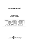
1
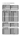
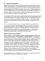
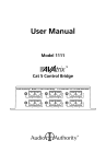
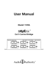
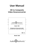
User Manual
SELECT
INPUT
IR
1
2
POWER
Model 1372
2 x 1 Switcher
DC
POWER
HDMI OUTPUT
ON/OFF
HDMI INPUTS
1
2
5V-2A
Model 1372 and 1374
HDMI Switchers
EXTEND
IR
RS-232
2
Table Of Contents
1.0
Introduction . . . . . . . . . . . . . . . . . . . . . . . 4
2.0
Specifications
3.0
Checking Package Contents . . . . . . . . . . . . . . . 6
4.0
Connecting The Hardware
5.0
Operating The Unit . . . . . . . . . . . . . . . . . . . 8
6.0
Troubleshooting . . . . . . . . . . . . . . . . . . . . . 8
7.0
RS-232 Code Information . . . . . . . . . . . . . . . . 9
8.0
Limited Warranty . . . . . . . . . . . . . . . . . . .
10
9.0
Regulatory Compliance . . . . . . . . . . . . . . . .
11
10.0 Contact Information . . . . . . . . . . . . . . . . . .
11
. . . . . . . . . . . . . . . . . . . . . . 5
3
. . . . . . . . . . . . . . . 6
1.0 INTRODUCTION
Thanks for purchasing this Model 1372, or 1374 HDMI Switcher
from Audio Authority. These switchers are designed to provide a
way to switch between multiple HDMI sources to one display device
without signal degradation or loss of encryption. The 1372 and
1374 are HDCP compliant. Audio Authority also offers an extensive
line of audio and video switchers, converters and distribution amps
available for purchase online at www.audioauthority.com.
1.1 Liability Statement
Every effort has been made to ensure that this product is free of
errors. Audio Authority cannot be held liable for the use of this
hardware or any direct or indirect consequential damages arising
from its use. It is the responsibility of the user of the hardware
to check that it is suitable for his/her requirements and that it is
installed correctly. All rights reserved. No parts of this manual may
be reproduced or transmitted by any form or means electronic
or mechanical, including photocopying, recording or by any
information storage or retrieval system without the written consent
of the publisher.
Audio Authority reserves the right to revise any of its hardware and
software following its policy to modify and/or improve its products
where necessary or desirable. This statement does not affect the
legal rights of the user in any way.
Audio Authority and the Double-A Symbol are registered trademarks
of Audio Authority Corp. Copyright April, 2006, all rights reserved.
All third party trademarks and copyrights are recognized.
HDMI, the HDMI logo and High-Definition Multimedia Interface are
trademarks or registered trademarks of HDMI Licensing LLC.
1.2 FEATURES
• Switches from two to four HDMI sources
• Supports 480i, 480p, 720p, 1080i and 1080p
• HDMI Certified by Silicon Images ATC Laboratory
• Supports DDWG standard for HDMI compliant monitors
• HDCP compliant, RoHS compliant
• IR remote control capability
• RS-232 control port provided
4
2.0 SPECIFICATIONS
Performance
Resolutions Supported
480i, 480p, 720p, 1080i, 1080p and others
Maximum Cable Distance
Inputs: 50 ft. max, Output 50 ft. max
HDCP Function
HDCP compliant
I/O Connectors
Inputs
Model 1372: HDMI, TMDS x2
Model 1374: HDMI, TMDS x4
Outputs
HDMI, TMDS x1 (All models)
Mechanical
Dimensions (H-W-D)
1.1 x 8.7 x 2.8 (28 x 220 x 71mm)
Weight
1.0 lbs (480g)
Warranty
Limited Warranty
1 Year Parts and Labor
Environmental
Operating Temperature
0 to +40˚ C (+32˚ to +104˚ F)
Operating Humidity
10% to 85% (Non-condensing)
Storage Temperature
-20˚ to +60˚ C (+20˚ to +140˚ F)
Storage Humidity
10% to 85% (Non-condensing)
Remote Control
Serial Interface
RS-232
Infrared
IR Remote Included
Power Requirements
External Power Supply
+5 VDC @ 2A
Regulatory Approvals
Switcher
FCC, CE, RoHS, HDMI ATC
Power Supplies
UL, CE, CSA, CEC, RoHS
Accessories Included
AC Power Adapter
(USA)
Remote Control
Infrared
Mounting Hardware
Remote Mounting Kit
Rack Mounting Kit
User Manual
5
3.0 CHECKING PACKAGE CONTENTS
Before attempting to use this unit, please check the packaging and
make certain the following items are contained in the shipping
carton:
• HDMI Distribution Amplifier
• 5 VDC Power Adapter
• IR Remote Control
• Remote Mounting Kit
• User Manual
Note: Please keep the original packing material in case the unit
ever needs to be returned. If you find any items are missing,
contact Audio Authority immediately. Have the Model Number,
Serial Number and Invoice available for reference when you call.
4.0 CONNECTING THE HARDWARE
For reference purposes, only the 1372 is depicted below. The 1374
is larger and has two more inputs. Please study the drawings below
and become familiar with the location of the controls, status LEDs,
signal inputs, signal output and the power input.
• Connect an HDMI approved cable, no more than 50 feet in length,
from each of the HDMI sources to the inputs of the switcher.
• Connect the output of the switcher to the destination device using
an HDMI approved cable no more than 50 feet long*.
• Connect the extended IR remote cable if desired.
• Connect the power adapter, first to the switcher and then to the
AC outlet.
Model 1372 HDMI Switcher, front view. Model 1374 is similar.
SELECT
INPUT
IR
1
2
POWER
Model 1372
2 x 1 Switcher
ON/OFF
Model 1372 HDMI Switcher, rear view. Model 1374 is similar.
DC
POWER
HDMI OUTPUT
HDMI INPUTS
1
2
5V-2A
6
EXTEND
IR
RS-232
* Proper operation of HDMI switchers depends on the use of premium
quality HDMI cables that provide low loss, high bandwidth signal
handling. The distance specification of 50 feet is for HDMI signals
up to 1080i; this specification cannot be guaranteed unless cables
meeting these standards are used throughout the system.
4.1 Installation of Mounting Components
The switchers can be mounted on any flat surface. Attach the two
“L” shaped mounting brackets to the product using the furnished
hardware and then attach the combined assembly to the desired
location. Note that the holes on the brackets are offset to allow
easier mounting to the flat surface after you’ve attached the
brackets to the switcher.
TOP VIEW
1372 OR 1374
FRONT VIEW
1372 OR 1374
FLAT SURFACE
7
5.0 OPERATING THE UNIT
Power and input selection are controlled from one multi-purpose
switch. To turn the switcher on, press the Input Select – Power
On/Off switch. Once the unit is in the operating state, pressing the
switch causes the input selection to advance each time it is pressed.
(An LED lights to show which input is active.) Once the highest
input number is reached, pressing the switch again will select input
number 1. Pressing and holding the switch for two (2) seconds will
cause the unit to power off.
For greater flexibility, an Infrared remote control is also provided.
In the case of the remote, there are separate buttons for the power
and input sources. Point the remote control at the unit and press the
power button to turn the switcher on or off. Press the appropriate
input select button to cause the desired input to appear on the
switcher’s output.
6.0 TROUBLESHOOTING
• First make certain that the input cable is no more than 50 feet
long and none of the output cables is more than 50 feet long (for
signals up to 1080i) and are of the highest possible quality.
• Make certain that the switcher is receiving power by looking at
the power LED.
• If you still experience problems using the switcher, you should
attempt to determine what is wrong by first attaching the source
devices directly to the destination device in turn using the same
cables you are using with the switched system. This is a way of
determining if the problem is due to bad cables or a problem
with the other devices. If you are unable to obtain a signal using
this simplified path, suspect the cables, a source device or the
destination device.
• Remember that HDMI devices communicate with one another
so the source device and all destination devices must be fully
HDMI capable. In addition, HDCP encryption requires processing
dependent on the equipment you have connected to both the
source and destination devices.
If the problem still persists after trying the above suggestions,
contact the Audio Authority Technical Service department via email:
[email protected], or call 800-322-8346 or 859-233-4599.
8
7.0 RS-232 CODE INFORMATION
Transmission Format
Baud Rate:
57600 BPS
Data Byte:
8 bits
Parity:
None
Stop Bit:
1
Modem Cable Pinouts
Switcher End
Controller End
Pin
Definition
Pin
Definition
1
NC
1
NC
3
TxD
4
2
RxD
2
RxD
3
3
TxD
4
NC
4
NC
5
GND
5
GND
6
NC
6
NC
7
NC
7
NC
8
NC
8
NC
9
NC
9
NC
2X1 Commands
Command Code
Description
0x01
Port 1 On
0x02
Port 2 On
0x05
Power On/Off
4X1 Commands
Command Code
Description
0x01
Port 1 On
0x02
Port 2 On
0x03
Port 3 On
0x04
Port 4 On
0x05
Power On/Off
9
8.0 LIMITED WARRANTY
Should any consumer use product from Audio Authority fail due to
defects in materials or workmanship within one year from the date
of the original sale to the end-user, Audio Authority guarantees that
we will replace the defective product at no cost. Freight charges for
the replacement unit will be paid by Audio Authority (Ground service
only). A copy of the invoice showing the item number and date of
purchase (proof-of-purchase) must be submitted with the defective
unit to constitute a valid in-warranty claim.
Units that fail after the warranty period has expired may be returned
to the factory for repair at a nominal charge, if not damaged beyond
the point of repair. All freight charges for out-of-warranty returns
for repair are the responsibility of the customer. Units returned for
repair must have a Return Authorization Number assigned by the
factory.
This is a limited warranty and is not applicable for products which,
in our opinion, have been damaged, altered, abused, misused, or
improperly installed. Audio Authority makes no other warranties
either expressed or implied, including limitation warranties as to
merchantability or fitness for a particular purpose. Additionally,
there are no allowances or credits available for service work or
installation performed in the field by the end user.
Warranty Service Procedures
If you suspect a product defect, contact Audio Authority’s Technical
Service Department at 800-322-8346 or 859-233-4599 for assistance in
verifying the problem. If a defect or potential defect is suspected, a
replacement unit will be shipped immediately on a defect-exchange
basis and a Return Authorization Number will be issued for the
return of the defective product. Replacement units are sent out at
the Manufacturer’s Suggested Retail Price which is debited to the
Customer’s Credit Card at the time of shipment. Once we receive
the defective unit back at the factory, it will be evaluated under the
conditions of this warranty and if found to be in-warranty, a full
credit will be issued to the Customer’s Credit Card. Return freight
charges for the defective unit are the customer’s responsibility.
Please contact our Technical Service Department for complete details
concerning all in and out of warranty service matters.
We appreciate your confidence in our products and services and will
always strive to meet or exceed your needs.
10
9.0 REGULATORY COMPLIANCE
The 1372, and 1374 Switchers have been tested for compliance with
appropriate FCC and CE rules and regulations and are also RoHS
compliant.
The Power Adaptor/Supplies have been tested for compliance with
UL, CE and CSA rules and regulations and are also RoHS compliant.
10.0 CONTACT INFORMATION
Should you have questions or require assistance with this product in
areas not covered by this manual, please contact Audio Authority
using the information below.
Audio Authority Technical Service
800-322-8346 M-F 8:30 AM to 5:00 PM, EST
International: 859-233-4599 Fax: 859-233-4510
Send email to: [email protected]
Audio Authority Corporation
2048 Mercer Road
Lexington, Kentucky 40511-1071
USA
11
2048 Mercer Road, Lexington, Kentucky 40511-1071
Phone: 859-233-4599 • Fax: 859-233-4510
Customer Toll-Free USA & Canada: 800-322-8346
Website: http://www.audioauthority.com
E-069
12/06