1
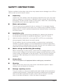
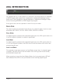
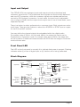
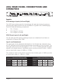
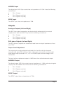
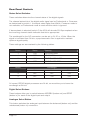
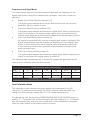
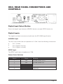
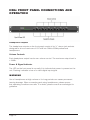
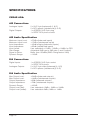
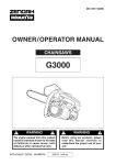
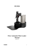
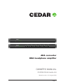
ADA converter HDA headphone amplifier Owner’S Manual © 2009 CEDAR Audio Ltd Manual version 1.00: August 2009 Page 1 Page 2 Table of Contents Safety Instructions......................................................................................... 5 ADA: Introduction.......................................................................................... 6 ADA: Rear Panel Connections and Operation.............................................. 8 HDA: Introduction........................................................................................ 12 HDA: Rear Panel Connections and Controls............................................... 13 HDA: Front Panel Connections and Operation........................................... 14 CE Declaration of Conformity...................................................................... 15 Specifications - CEDAR ADA...................................................................... 16 Specifications - CEDAR HDA ..................................................................... 17 Licence and Limited Warranty.................................................................... 18 Page 3 Page 4 Safety Instructions Failure to adhere to the safety instructions may cause severe damage to an ADA or HDA as well as risk of electric shock. nUnpacking Unpack the unit carefully. Save the packing materials since you may need them to transport it in the future. In addition to this manual, the unit and its packaging, the box should contain a mains lead, rubber feet, rackmounting accessories and a warranty registration card. n Water and moisture The unit must not be exposed to rain or moisture. If it is brought directly from a cold environment into a warm one, moisture may condense inside it. Always allow it to reach ambient temperatures naturally before connecting the mains power. n n n n Installation site To maintain reliability and prolong operating life, observe the following: the temperature should be maintained between 5° and 30° Celsius relative humidity should be in the range 30% to 80% non-condensing strong magnetic fields should not exist nearby. Do not subject the unit to strong sunlight, excessive dust, mechanical vibration or periodic shocks. It is not susceptible to excessive heat buildup, but should be installed away from heat sources such as radiators and audio devices that produce large amounts of heat. n Mains voltage and Earthing (Grounding) Before connecting to mains power, ensure that the voltage selector is set to the correct voltage for the local mains supply, and that the fuse is of the correct rating, as indicated on the rear panel. The unit must be earthed to ensure a safe operating environment and to provide electromagnetic shielding. nConnections Turn off the power to all equipment before making any connections. nCleaning Clean the unit only with a dry cloth. Never use abrasive pads or liquid cleaners such as alcohol or benzene. n Damage requiring service The unit contains no user-serviceable parts and should not be opened by unauthorised personnel. It should be returned to qualified service agents when it has been exposed to liquids, when it fails to function correctly, when it has been dropped, or when the case is damaged. Page 5 ADA: Introduction The CEDAR ADA is a 24-bit, 96kHz 1U rackmount unit that produces an AES/EBU or SPDIF digital audio output from a balanced or unbalanced analogue stereo audio input. It also produces a stereo balanced or unbalanced analogue output from an incoming AES/EBU or SPDIF digital input signal. At any given time, the unit operates in one of four sync modes: Master Mode The clock signals are generated internally by an on-board master clock at a userselectable rate: 32kHz, 44.1kHz, 48kHz, 64kHz, 88.2kHz or 96kHz. Slave Mode If a digital signal is present at the selected digital input, the ADA synchronises to it. If no such signal is present, no output is generated. Auto Mode If a digital signal is present at the selected digital input, the ADA synchronises to it. If no such signal is present, the ADA uses its internal master clock at the userselected sample rate. Auto Lock Mode This operates in the same manner as Auto Mode except that, if no digital signal is present, the ADA uses its internal master clock running at the most recently synchronised sample rate. When operating in any other than Master Mode, the front panel power LED will flash whenever the ADA is not synchronised to an incoming digital signal. Page 6 Input and Output The CEDAR ADA has analogue inputs and outputs at both professional and consumer signal levels. The professional level signals are electronically balanced and use XLR connectors, while the consumer signals are unbalanced and are carried by RCA (phono) connectors. In each case, the input level is adjustable over a range of 18dB, and the output level may be set to one of three levels, each separated by 6dB. There is a button to select professional or consumer input. Both outputs are active at all times. There are also buttons to select the AES/EBU or SPDIF input or output for the D/A and A/D sections. You may define the channel status bits embedded within the digital audio. For sample rates of 32kHz, 44.1kHz and 48kHz, the status bits can be set to Professional or Consumer mode. For sample rates above 48kHz, the status bits will be forced to Professional mode because the ADA does not support Consumer mode at these rates. Front Panel LED The LED on the front panel is normally lit to indicate that power is present. Flashing indicates either (i) a loss of digital input or (ii) that the unit is being calibrated. Block Diagram AES/EBU Digital Source Select AES Receiver Digital Input L DAC R SPDIF L Recovered Clock R Master Clock Generator Analogue Input Select Professional Balanced Consumer Unbalanced L R Analogue Output Consumer Unbalanced Frequency Select L AES/EBU R Analogue Input Professional Balanced Gain Gain ADC AES Transmitter Digital Output Digital Send Select SPDIF Page 7 ADA: Rear Panel Connections and Operation ANALOGUE INPUTS INPUT SELECT FULL SCALE L dB SETTINGS ANALOGUE OUTPUTS L LEVEL L LEFT R R RIGHT DIGITAL INPUTS AES/EBU OUTPUT S/PDIF S/PDIF AES/EBU AES/EBU FREQUENCIES AND SYNC MODES STATUS CEDAR ADA CONVERTER 230V 100mA 115V 200mA FUSE R LEFT RIGHT CAUTION: DIGITAL OUTPUTS AES/EBU INPUT Disconnect the mains supply before removing the equipment covers. 115V - 230V This product must be earthed Inputs XLR Analogue Inputs (Left and Right) The XLR 3-pin sockets used for the analogue left and right channel inputs are electronically balanced and have an impedance of greater than 10kΩ bridging. Each XLR has the following connections: n n n Pin 1: Screen. Pin 2: Signal +ve (hot) Pin 3: Signal -ve (cold) RCA Phono Inputs (Left and Right) The left and right RCA (phono) analogue inputs are unbalanced and have an impedance of greater than 20kΩ. Input Level Adjustment The input gain can be adjusted individually for the left and right channels using the DIP switches and the preset potentiometers accessible on the rear panel. The input gain can be set such that signals of +12, +18 or +24dBu generate full-scale signals in the digital domain. Individual preset controls provide a further ± 3dB to give an input level range of +9dBu to +27dBu. The consumer input on the phono connector has a further gain of 10dB to provide an input level range of -1dBu to +17dBu. Input Level Settings (dB) Output Level Settings (dB) Switch +12 +18 +24 Switch +12 +18 +24 1 OFF ON ON 3 OFF ON ON 2 OFF OFF ON 4 OFF OFF ON Page 8 AES/EBU Input The digital input XLR 3-pin socket has an impedance of 110Ω. It has the following connections: n n n Pin 1: Screen. Pin 2: Signal +ve (hot) Pin 3: Signal -ve (cold) SPDIF Input The SPDIF input has an impedance of 75Ω. Outputs Analogue Outputs (Left and Right) The XLR 3-pin output connectors are electronically balanced with an output impedance of less than 50Ω. They have the following connections : n n n Pin 1: Screen. Pin 2: Signal +ve (hot) Pin 3: Signal -ve (cold) RCA phono Outputs (Left and Right) The RCA (phono) outputs are unbalanced and have an output impedance of less than 75Ω. Output Level Adjustment The output gain can be adjusted individually for the left and right channels using the rear panel DIP switches. Each output gain can be set such that a fullscale digital output provides +12, +18 or +24dBu output on the analogue XLR connectors. The level at the unbalanced output is 10dB lower than at the balanced output. AES/EBU Output The digital output XLR 3-pin socket has an impedance of 110Ω, and output signals comply with IEC 60958. The socket has the following connections: n n n Pin 1: Screen. Pin 2: Signal +ve (hot) Pin 3: Signal -ve (cold) SPDIF Output The SPDIF output has an impedance of 75Ω. Page 9 Rear Panel Controls Status Select Switches These switches determine the channel status of the digital signals. The channel status bits of the digital audio signal can be Professional or Consumer, as determined by switch 1. At sample rates higher than 48kHz, Consumer mode is not available, so Professional mode is used and this switch is ignored. If de-emphasis is selected (switch 2) the ADA will decode 50/15µs emphasis when the incoming channel status indicates that this is appropriate. The wordlength for the A/D conversion can be set to 24, 20 or 16 bits. When the signal is truncated from 24 bits, a psychoacoustic filter is applied to maintain optimum signal quality. These settings are summarised by the following tables: Switch Status Meaning 1 ON PROFESSIONAL 1 OFF CONSUMER 2 ON DE-EMPHASIS AUTO 2 OFF DE-EMPHASIS OFF Switch Wordlength 16-bit 20-bit 24-bit 3 OFF OFF ON 4 OFF ON ON All current CEDAR digital processors are 24-bit, so we advise you to leave the wordlength at 24 bits. Digital Select Buttons These buttons allow you to switch between AES/EBU (button out) and SPDIF (button in) for each of the digital input and output. Analogue Select Button This button switches the analogue input between the balanced (button out) and the unbalanced (button in) connectors. Page 10 Frequency and Sync Mode This rotary switch selects the Synchronisation Mode and the frequency of the digital output when using the on-board clock generator. There are 4 modes of operation: n Master Sync Mode (Switch positions 0–5) The digital output sample rate is set by and locked to the internal clock generator. No sync signal is used. n Auto Sync Mode (Switch positions 6–B) The digital output sample rate follows the digital input. When a digital input signal is not present, the output sample rate is set by and locked to the internal clock generator at the frequency determined by the switch position. n Auto-Lock Sync Mode (Switch position C) No output is generated until lock with a digital input signal is achieved. The digital output sample rate then follows the digital input. If the digital input signal is removed then the output sample rate will be set by and locked to the internal on-board clock generator at the frequency closest to the previous digital input. n Slave Sync Mode (Switch position D) The digital output sample rate follows the digital input. When a digital input signal is not present the digital output is turned off. The following table summarises this. It shows the sample rate generated by the internal clock in Master and Auto Sync modes. FREQUENCIES AND SYNC MODES kHz 32 44.1 48 64 88.2 96 MASTER 0 1 2 3 4 5 AUTO 6 7 8 9 A B AUTOLOCK = C SLAVE MODE = D Test/Calibration Mode The calibration cycle calibrates the gain and the zero reference of the A/D converter. For optimum performance, the ADA should be calibrated after you change the Gain settings, ideally after a 10-15 minute settling period. To calibrate the unit, set the rotary FREQUENCIES AND SYNC MODES switch to position “F”. The power LED on the front panel will flash quickly for 2 – 3 seconds and will illuminate fully when the unit is calibrated. Once calibration is complete, reset the rotary switch to the position that you require. Page 11 HDA: Introduction The CEDAR HDA headphone amplifier is a 24-bit, 96kHz rackmount unit that receives an AES/EBU or SPDIF digital input signal and converts it to six individually buffered ¼” (6.3mm) stereo headphone outputs, each with its own volume control. Input and Output The input connectors comprise a balanced XLR-3 for the AES/EBU input and an unbalanced phono connector for the S/PDIF input. A button located on the rear panel determines which input is active, and de-emphasis on the output can be controlled via a dipswitch. If de-emphasis is selected, the HDA will decode 50/15µs emphasis when indicated by the status bits in the incoming digital audio. Block Diagram AES/EBU Source Select AES Receiver DAC Audio output amp Stereo output jack SPDIF Digital Input Page 12 x6 HDA: Rear Panel Connections and controls Digital Input Select Button Switch the digital input between AES/EBU (button out) and S/PDIF (button in). Digital Inputs The signals on these connectors should meet the IEC 60968 specification. AES/EBU Input The XLR 3-pin socket has an impedance of 110Ω. It has the following connections: n n n Pin 1: Screen Pin 2: Signal +ve (hot) Pin 3: Signal -ve (cold) SPDIF Input The SPDIF input has an impedance of 75Ω. Status Select Switches Switch Status Meaning 1 ON DE-EMPHASIS AUTO 1 OFF DE-EMPHASIS OFF 2 Reserved 3 Reserved 4 Reserved Page 13 HDA: Front Panel Connections and Operation Headphone Outputs The headphone outputs on the front panel consist of six ¼” stereo jack sockets designed to drive a maximum of 150 mW into 32Ω to 600Ω professional headphones. Volume Controls Each headphone output has its own volume control. The maximum output level is +12dBu. Power & Signal Indicator The LED on the front panel is normally lit to indicate that power is present on the unit. Flashing indicates a loss of a valid digital input signal. WARNING Use of headphones at high volume or for long periods can cause permanent hearing damage. When connecting and using headphones, please ensure that operating conditions are safe. If in doubt, please consult an audiologist for guidance. Page 14 CE Declaration of Conformity Equipment: CEDAR ADA and HDA Date of issue: 19 February 2003 (CEDAR ADA) Date of issue: 1 October 2009 (CEDAR HDA) Manufacturer: CEDAR Audio Ltd Address: 20 Home End, Fulbourn, Cambridge CB21 5BS, UK This is to certify that the aforementioned equipment, when used in accordance with the instructions in this manual, fully conforms to the protection requirements of the following EC Council Directives: on the approximation of the laws of the member states relating to: Electromagnetic Compatibility: EN55103-1: 1997 Limits of disturbance for audio apparatus for professional use. For use in environments 1 to 4. EN55103-2: 1997 Immunity requirements for audio apparatus for professional use. For use in environments 1 to 4. Safety: EN60950: 1992 Safety of Information Technology Equipment, Including Electrical Business Equipment. Page 15 Specifications CEDAR ADA: A/D Connections Analogue Inputs: Digital Outputs: 2 2 1 1 x x x x XLR 3-pin (balanced) (L & R) RCA phono (unbalanced) (L & R) AES/EBU XLR 3-pin plug SPDIF RCA phono socket A/D Audio Specification Maximum Input Level: +27dBu (balanced inputs) Maximum Input Level: +17dBu (unbalanced inputs) Input Impedance: >10kΩ bridging (balanced inputs) Input Impedance: >20kΩ (unbalanced inputs) Input Levels:User selectable +12dBu, +18dBu, +24dBu for FSD Gain Range:Adjustable 3dB loss to 3dB gain (L and R adjust) Signal to Noise: Better than 109dBfs (RMS A-weighted at 24bit) Dynamic Range: >110dB D/A Connections Digital Inputs: Analogue Outputs: 1 1 2 2 x x x x AES/EBU XLR 3-pin socket SPDIF RCA phono XLR 3-pin male (balanced) (L & R) RCA phono (unbalanced) (L & R) D/A Audio Specification Max Output Level: +24dBu (balanced outputs) Max Output Level: +14dBu (unbalanced outputs) Output Impedance: <50Ω (balanced outputs) Output Impedance: <75Ω (unbalanced outputs) Dynamic Range: >100dB Output Level (bal):User selectable 12dBu, 18dBu or 24dBu Output Level (unbal):User selectable 2dBu, 8dBu or 14dBu Page 16 CEDAR HDA: D/A Connections Digital Inputs: 1 x AES/EBU XLR 3-pin socket 1 x SPDIF RCA phono D/A Audio Specification Sampling Frequencies: Dynamic Range: 30kHz – 100kHz >100dB Outputs Headphones: Power: Maximum Output Level: Headphone Gain: 6 x ¼” (6.35mm) A/B gauge 3-pole stereo jack sockets 150 mW into 32Ω - 600Ω (each ouput) +12dBu -80dBu to +12dBu Common: Mains Power Mains Input: Consumption: IEC, 110-120VAC or 220-240VAC switchable, 50-60Hz 10W max Physical Dimensions Dimensions (Boxed) Weight 480mm (W) x 108mm (D) x 44mm (H) (nominally 1U) 530mm (W) x 205mm (D) x 60mm (H) 2.2kg (Gross) 1.6kg (Net) CEDAR Audio Ltd reserves the right to alter specifications without notice. E&OE. Page 17 Licence and Limited Warranty 1. DEFINITIONS In this Licence and Limited Warranty the following words and phrases shall bear the following meanings: ‘the Company’ is CEDAR Audio Limited of 20 Home End, Fulbourn, Cambridge CB21 5BS, UK; ‘the System’means an instance of the CEDAR ADA converter or the CEDAR HDA headphone amplifier; ‘this Document’ 2. means this Licence and Limited Warranty. ISSUE AND USE OF THE SYSTEM 2.1 The terms and conditions of this Document are implicitly accepted by any person or body corporate who shall at any time use or have access to the System, and are effective from the date of supply of the System by CEDAR Audio Limited to its immediate customer. 2.2 The Company hereby grants to the Licensee and the Licensee agrees to accept a non-exclusive right to use the System. 3. PROPERTY AND CONFIDENTIALITY 3.1 The System contains confidential information of the Company and its suppliers and all copyright, trade marks, trade names, styles and logos and other intellectual property rights in the System including all documentation and manuals relating thereto are the exclusive property of the Company and its suppliers. The Licensee acknowledges that all such rights are the property of the Company and its suppliers and shall not question or dispute the ownership of any such rights nor use or adopt any trading name or style similar to that of the Company and/or its suppliers. 3.2 The Licensee shall not attempt to reverse engineer, modify, copy, merge or transcribe the whole or any part of the System or any information or documentation relating thereto. 3.3 The Licensee shall take all reasonable steps to protect the confidential information and intellectual property rights of the Company and its suppliers. 4. LIMITED WARRANTY AND POST-WARRANTY OBLIGATIONS 4.1 The Company warrants that the System will perform substantially in accordance with the appropriate section of this manual for a period of one year from the date of supply to the Company‘s immediate customers. 4.2 The Company will make good at its own expenses by repair or replacement any defect or failure that develops in the System within one year of supply to the Company‘s immediate customer. 4.3 The Company shall have no liability to remedy any defect, failure, error or malfunction that arises as a result of any improper use, operation or neglect of the System, or any attempt to repair or modify the System by any person other than the Company or a person appointed with the Company‘s prior written consent. 4.4 In the case of any defect or failure in the System occurring more than twelve months after its supply to the Company‘s immediate customer the Company will at its option and for a reasonable fee make good such defect or failure by repair or replacement (at the option of the Company) subject to the faulty equipment having first been returned to the Company. The Company will use reasonable efforts to return repaired or replacement items promptly, all shipping, handling and insurance costs being for the account of the Licensee. 4.5 The above undertakings 4.1 to 4.4 are accepted by the Licensee in lieu of any other legal remedy in respect of any defect or failure occurring during the said period and of any other obligations or warranties expressed or implied including but not limited to the implied warranties of saleability and fitness for a specific purpose. 4.6 The Licensee hereby acknowledges and accepts that nothing in this Document shall impose upon the Company any obligation to repair or replace any item after a time when it is no longer produced or offered for supply by the Company or which the Company certifies has been superseded by a later version or has become obsolete. Page 18 5.FORCE MAJEURE The Company shall not be liable for any breach of its obligations hereunder resulting from causes beyond its reasonable control including, but not limited to, fires, strikes (of its own or other employees), insurrection or riots, embargoes, container shortages, wrecks or delays in transportation, inability to obtain supplies and raw materials, or requirements or regulations of any civil or military authority. 6. WAIVER The waiver by either party of a breach of the provisions hereof by the other shall not be construed as a waiver of any succeeding breach of the same or other provisions, nor shall any delay or omission on the part of either party to exercise any right that it may have under this Licence operate as a waiver of any breach or default by the other party. 7.NOTICES Any notices or instruction to be given hereunder shall be delivered or sent by first-class post or telecopier to the other party, and shall be deemed to have been served (if delivered) at the time of delivery or (if sent by post) upon the expiration of seven days after posting or (if sent by telecopier) upon the expiration of twelve hours after transmission. 8.ASSIGNMENT AND SUBLICENSING The Licensee may at his discretion assign the System and in doing so shall assign this Licence its rights and obligations to the purchaser who shall without reservation agree to be bound by this Licence. The original Licensee and any subsequent Licensees shall be bound by the obligations of this Licence in perpetuity. 9. LIMITATION OF LIABILITY The Company‘s maximum liability under any claim including any claim in respect of infringement of the intellectual property rights of any third party shall be, at the option of the Company either: (a)return of a sum calculated as the price received for the System by the Company from its immediate customer depreciated on a straight line basis over a one year write-off period; or (b)repair or replacement of those components of the System that do not meet the warranties contained within this Document. The foregoing states the entire liability of the Company to the Licensee. 10.CONSEQUENTIAL LOSS Even if the Company has been advised of the possibility of such damages, and notwithstanding anything else contained herein the Company shall under no event be liable to the Licensee or to any other persons for loss of profits or contracts or damage (whether direct or consequential) arising in connection with the System or any modification, variation or enhancement thereof and including any documentation or data provided by the Company or for any other indirect or consequential loss. 11.ENTIRE AGREEMENT The Company shall not be liable to the Licensee for any loss arising in connection with any representations, agreements, statements or undertakings made prior to the date of supply of the System to the Licensee. 12.TERMINATION This Licence may be terminated forthwith by the Company if the Licensee commits any material breach of any terms of this Licence. Forthwith upon such termination the Company shall have immediate right of access to the System for the purpose of removing it. 13. SEVERABILITY Notwithstanding that the whole or any part of any provision of this Document may prove to be illegal or unenforceable the other provisions of this Document and the remainder of the provision in question shall remain in full force and effect. 14. HEADINGS The headings to the Clauses are for ease of reference only and shall not affect the interpretation or construction of this Document. 15. LAW This Document shall be governed by and construed in accordance with English law and all disputes between the parties which cannot be resolved by negotiation shall be determined by arbitration in England in accordance with the Arbitration Act 1950 and 1979. Page 19 CEDAR ADA & HDA CEDAR ADA Serial number Inspection date QC Engineer CEDAR HDA Serial number Inspection date QC Engineer CEDAR Audio Ltd 20 Home End Fulbourn Cambridge CB21 5BS United Kingdom www.cedaraudio.com [email protected] Page 20