1
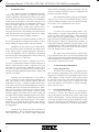
Film-Tech The information contained in this Adobe Acrobat pdf file is provided at your own risk and good judgment. These manuals are designed to facilitate the exchange of information related to cinema projection and film handling, with no warranties nor obligations from the authors, for qualified field service engineers. If you are not a qualified technician, please make no adjuatments to anything you may read about in these Adobe manual downloads www.film-tech.com FTX-1001 FTX-1501 FTX-2001 CFT-1800 Power Amplifier Series III Operating Manual ASHLY AUDIO INC. 847 Holt Road Webster, NY 14580-9103 Phone: (716) 872-0010 Toll-Free: (800) 828-6308 Fax: (716) 872-0739 Internet: http://www.ashly.com/ Operating Manual - FTX-1001, FTX-1501, FTX-2001, CFT-1800 Power Amplifier Table Of Contents 2 1 INTRODUCTION . . . . . . . . . . . . . . . . . . . . . . . . . . . . . . . . . . . . . . . . . . . . . . . . . 4 2 UNPACKING . . . . . . . . . . . . . . . . . . . . . . . . . . . . . . . . . . . . . . . . . . . . . . . . . . . . . . 4 3 AC POWER REQUIREMENTS . . . . . . . . . . . . . . . . . . . . . . . . . . . . . . . . . . . . . . 3.1 AC Voltage Requirements. . . . . . . . . . . . . . . . . . . . . . . . . . . . . . . . . . . . . . . . . . 3.2 Current Requirements . . . . . . . . . . . . . . . . . . . . . . . . . . . . . . . . . . . . . . . . . . . . . 3.3 AC Grounding Requirements . . . . . . . . . . . . . . . . . . . . . . . . . . . . . . . . . . . . . . . 4 CABLE REQUIREMENTS . . . . . . . . . . . . . . . . . . . . . . . . . . . . . . . . . . . . . . . . . . 5 4.1 Input Cables. . . . . . . . . . . . . . . . . . . . . . . . . . . . . . . . . . . . . . . . . . . . . . . . . . . . . 5 4.2 Output Cables . . . . . . . . . . . . . . . . . . . . . . . . . . . . . . . . . . . . . . . . . . . . . . . . . . . 5 5 RACK-MOUNTING REQUIREMENTS. . . . . . . . . . . . . . . . . . . . . . . . . . . . . . . 5.1 Mechanical . . . . . . . . . . . . . . . . . . . . . . . . . . . . . . . . . . . . . . . . . . . . . . . . . . . . . 5.2 Cooling . . . . . . . . . . . . . . . . . . . . . . . . . . . . . . . . . . . . . . . . . . . . . . . . . . . . . . . . 5.3 Grounding . . . . . . . . . . . . . . . . . . . . . . . . . . . . . . . . . . . . . . . . . . . . . . . . . . . . . . 5 5 5 5 6 FRONT PANEL FEATURES . . . . . . . . . . . . . . . . . . . . . . . . . . . . . . . . . . . . . . . . 6.1 Power Switch. . . . . . . . . . . . . . . . . . . . . . . . . . . . . . . . . . . . . . . . . . . . . . . . . . . . 6.2 Thermal Status Meters . . . . . . . . . . . . . . . . . . . . . . . . . . . . . . . . . . . . . . . . . . . . 6.3 Output Meters . . . . . . . . . . . . . . . . . . . . . . . . . . . . . . . . . . . . . . . . . . . . . . . . . . . 6.4 Clipping Indicator . . . . . . . . . . . . . . . . . . . . . . . . . . . . . . . . . . . . . . . . . . . . . . . . 6.5 Protect Indicator . . . . . . . . . . . . . . . . . . . . . . . . . . . . . . . . . . . . . . . . . . . . . . . . . 6 6 6 6 6 7 7 REAR PANEL FEATURES . . . . . . . . . . . . . . . . . . . . . . . . . . . . . . . . . . . . . . . . . . 7.1 Inputs . . . . . . . . . . . . . . . . . . . . . . . . . . . . . . . . . . . . . . . . . . . . . . . . . . . . . . . . . . 7.2 Normal/Bridging Switch . . . . . . . . . . . . . . . . . . . . . . . . . . . . . . . . . . . . . . . . . . 7.3 Stereo/Parallel Mono Switch . . . . . . . . . . . . . . . . . . . . . . . . . . . . . . . . . . . . . . . 7.4 Level Controls . . . . . . . . . . . . . . . . . . . . . . . . . . . . . . . . . . . . . . . . . . . . . . . . . . . 7.5 Speaker Outputs - Binding Posts . . . . . . . . . . . . . . . . . . . . . . . . . . . . . . . . . . . . 8 8 9 9 9 9 8 INPUT OPTIONS . . . . . . . . . . . . . . . . . . . . . . . . . . . . . . . . . . . . . . . . . . . . . . . . . 8.1 Input Isolation Transformer . . . . . . . . . . . . . . . . . . . . . . . . . . . . . . . . . . . . . . . 8.2 Peak Limiter Compressor . . . . . . . . . . . . . . . . . . . . . . . . . . . . . . . . . . . . . . . . . 8.3 Two-Way Crossover . . . . . . . . . . . . . . . . . . . . . . . . . . . . . . . . . . . . . . . . . . . . . 8.4 Mic-Line Mixer . . . . . . . . . . . . . . . . . . . . . . . . . . . . . . . . . . . . . . . . . . . . . . . . . 11 11 11 11 11 4 4 4 5 Operating Manual - FTX-1001, FTX-1501, FTX-2001, CFT-1800 Power Amplifier 9 TYPICAL APPLICATIONS . . . . . . . . . . . . . . . . . . . . . . . . . . . . . . . . . . . . . . . . 9.1 Stereo Operation . . . . . . . . . . . . . . . . . . . . . . . . . . . . . . . . . . . . . . . . . . . . . . . . 9.2 Parallel Mono Operation . . . . . . . . . . . . . . . . . . . . . . . . . . . . . . . . . . . . . . . . . 9.3 Bridged Mono Operation . . . . . . . . . . . . . . . . . . . . . . . . . . . . . . . . . . . . . . . . . 12 12 12 13 10 DESIGN THEORY . . . . . . . . . . . . . . . . . . . . . . . . . . . . . . . . . . . . . . . . . . . . . . . . 13 11 TROUBLESHOOTING TIPS . . . . . . . . . . . . . . . . . . . . . . . . . . . . . . . . . . . . . . . 11.1 No Audio Output . . . . . . . . . . . . . . . . . . . . . . . . . . . . . . . . . . . . . . . . . . . . . . . 11.2 Distorted Sound . . . . . . . . . . . . . . . . . . . . . . . . . . . . . . . . . . . . . . . . . . . . . . . . 11.3 Hum or Buzz Noise . . . . . . . . . . . . . . . . . . . . . . . . . . . . . . . . . . . . . . . . . . . . . 14 14 14 14 12 DIMENSIONS . . . . . . . . . . . . . . . . . . . . . . . . . . . . . . . . . . . . . . . . . . . . . . . . . . . . 15 13 SPECIFICATIONS . . . . . . . . . . . . . . . . . . . . . . . . . . . . . . . . . . . . . . . . . . . . . . . . 16 14 WARRANTY POLICY . . . . . . . . . . . . . . . . . . . . . . . . . . . . . . . . . . . . . . . . . . . . . 16 15 SCHEMATICS . . . . . . . . . . . . . . . . . . . . . . . . . . . . . . . . . . . . . . . . . . . . . . . . . . . . 17 Caution: This power amplifier can produce dangerous output voltage levels, high power levels, and high sound pressure levels in loudspeakers. In order to minimize the risk of injury, damage, or hearing loss, please read the entire owner's manual before connecting to a sound system. WARNING: THIS APPARATUS MUST BE EARTHED 3 Operating Manual - FTX-1001, FTX-1501, FTX-2001, CFT-1800 Power Amplifier 1. INTRODUCTION The Ashly FTX Series III MOSFET amplifiers combine the sonic excellence of a high-end stereo amp with the ruggedness and stamina necessary in pro audio. The FTX Series III amps use lateral power MOSFETs (metal-oxide-semiconductor, field-effect transistors) for their superior audio fidelity and unmatched reliability as proven in Ashly amps for over fifteen years. These MOSFET output devices exhibit many superior performance characteristics over the conventional bipolar power transistors used in most conventional power amp designs. They are inherently self-regulating and do not exhibit many of the failure modes of bipolar transistors. MOSFETS have no thermal runaway tendency so the need for temperature tracking bias circuitry is eliminated, making the design simpler and more reliable. MOSFETS do not suffer from secondary breakdown (the primary failure mechanism in in bipolar transistors which requires complex dissipation limiting to avoid.) The MOSFET will even withstand a shorted load and self-limit the resulting high drain current without any protection circuitry for a short time. MOSFETS do not have a “minority carrier storage time” (a phenomenon found in bipolar transistors in which a certain amount of time is required to turn the transistor off). Therefore the MOSFET is said to be a “fast” device which can function very accurately and efficiently with high amplitude/high frequency signals and transient waveforms. The FTX series III amplifiers are the result of years of refinement to the original Ashly MOSFET design. The current circuit is cleaner, quieter, and more stable than ever before. A number of improvements have been made in the area of thermal management using new insulating materials and increased heatsink area, allowing even more robust performance into difficult loads. Protective systems have been refined to add even more insurance against gross faults such as short circuits and the application of speaker damaging signals to the amplifier. The module assembly is produced using assembly techniques including individual testing of each component before it is placed on the PC board, and a state-ofthe-art soldering system which insures excellent strength and ruggedness. The FTX series III uses the latest generation of lateral MOSFETS. These components also improve on a time honored design. The result is higher bandwidth, 4 improved power handling, and better matching. The allmetal case of these transistors results in a ruggedness not possible with plastic designs. The unmatched reliability of the power MOSFET output devices, the clever mechanical design, and the careful assembly techniques of the FTX Series III amplifiers ensure years of maintenance-free service. 2. UNPACKING As a part of our system of quality control, every Ashly product is carefully inspected before leaving the factory to ensure flawless appearance. After unpacking, please inspect for any physical damage. Save the shipping carton and all packing materials, as they were carefully designed to reduce to minimum the possibility of transportation damage should the unit again require packing and shipping. In the event that damage has occurred, immediately notify your dealer so that a written claim to cover the damages can be initiated. The right to any claim against a public carrier can be forfeited if the carrier is not notified promptly and if the shipping carton and packing materials are not available for inspection by the carrier. Save all packing materials until the claim has been settled. 3. AC POWER REQUIREMENTS 3.1 Voltage Requirements Your FTX Series III amplifier is supplied with a three conductor grounded AC power cord, and should be plugged into a standard 3-wire grounded electrical outlet which supplies 120VAC 50-60 Hz (some export models are wired for 100 or 240 volts and are labeled as such). In the event of line voltage sag, or “brown-out”, FTX Series III amplifiers will continue to operate normally, albeit with less power. 3.2 Current Requirements A 15 amp circuit is sufficient for normal operation down to 2Ω loads. The actual AC current consumption by the amplifier depends greatly on the audio signal and the load impedance. For typical audio program material with the amplifier driving both channels just peaking at the clipping level, the following AC line current capacities are recommended for system design purposes: Operating Manual - FTX-1001, FTX-1501, FTX-2001, CFT-1800 Power Amplifier FTX-1001 FTX-1501 FTX-2001 Idle .5A .6A 1.5A 8Ω loads 2 Amps 2.5 Amps 3.5 Amps 4Ω loads 3 Amps 4 Amps 6 Amps 7 Amps 10 Amps 2Ω loads --- Table 3.1: Recommended AC line current capacity All FTX Series III amplifiers consume less than 12 amps when operating at 1/8 power into 2Ω loads. This condition satisfies the UL, CSA and building electrical code requirements for a piece of audio equipment not to consume more than 80% of the current available when plugged into a grounded 15 amp outlet and operated at 1/8 of maximum power. AC Grounding Requirements To reduce the risk of ground loop hum, all system ground references should originate at the same point in your AC power distribution. Never remove the amplifier’s ground pin as it is both unlawful and dangerous, creating a potential shock hazard. Since power at the speaker load is a primary concern in system design, we have included a table to best determine appropriate wire gauge for your application. Table 4.1 lists the percentage of the speaker load power which would be lost in an arbitrary 100 ft run of 2-conductor cable. This table expresses the power loss as a percentage of the load’s power rather than the total amplifier output power, so that you can use this table to accurately determine power loss to the load at other cable lengths. For example, if you plan to deliver 100 watts to an 8Ω load through 50 ft of 14 ga. cable, the power loss in the cable would be 3.2% ÷ 2 = 1.6% of 100 watts or 1.6 watts lost in the cable. Table 4.1 also gives the resistance per 100 feet of common copper wire gauges. Wire Gauge Ω/100ft 8Ω load 4Ω load 2Ω load #8 #10 #12 #14 #16 #18 3.3 4. CABLE REQUIREMENTS 4.1 Input Cables Be sure to use shielded cable whether balanced or unbalanced. Shielding which is properly grounded will protect the signal from outside electrical interference such as RF, fluorescent lighting, even computer noise. As a general rule, unbalanced or single-ended (tip-sleeve) lines of less than 10 feet are satisfactory, but greater distances may require a balanced signal. Avoid running input lines in close proximity or parallel to long speaker lines, AC power cables, or power transformers, as this may generate hum or oscillation. 4.2 Output Cables The FTX Series III amplifiers are capable of delivering high levels of output current, therefore the wire gauge used for speaker cables is particularly important. Inadequate wire gauge adds significant resistance to the speaker’s own impedance, reducing the power which is actually delivered to the speaker. It will also result in a decrease in the damping factor and possible fire hazard. .0605Ω .1018Ω .1619Ω .2575Ω .4094Ω .6510Ω 0.8% 1.3% 2.0% 3.2% 5.1% 8.1% 1.5% 2.5% 4.0% 6.4% 10.2% 16.3% 3.0% 5.1% 8.1% 12.9% 20.5% 32.6% Table 4.1: Percentage of speaker load power lost in 100 foot run of 2-conductor cable. 5. RACK-MOUNTING REQUIREMENTS 5.1 Mechanical All Ashly amps are designed to fit in standard 19-inch racks. The front panel rack-mount ears are sufficiently strong for most applications. If you desire further integrity for mobile racks, we recommend using the four additional holes in the back of the chassis for supplemental rear-mounting (see dimensional drawings). 5.2 Cooling If using an FTX amplifier, be certain that both the front and back of the rack have unhindered access to free air flow. Fan direction is from front to back. It is not necessary to leave empty space above or below the FTX amplifiers, however the CFT-1800 will cool more efficiently with space above and below the chassis. The following chart indicates max BTU per hour for each amp under varying load conditions, so that accurate assessment of room ventilation needs can be made. Thermal output is approximated by subtracting audio output power from the total power consumption of the amplifier. All values assume the amplifier is driving both channels and just peaking at the clipping level. 5 Operating Manual - FTX-1001, FTX-1501, FTX-2001, CFT-1800 Power Amplifier - -27 -24 -21 -18 -1 - -27 -24 -21 -18 -1 Channel One Channel Two Output AC Power Off On FTX-1001 FTX-1501 FTX-2001 6. Idle 210 BTU 250 BTU 620 BTU 6.1 8Ω loads 550 BTU 580 BTU 760 BTU 4Ω loads 800 BTU 970 BTU 1340 BTU 2Ω loads --- 2030 BTU 2590 BTU Table 5.2: Max BTU per hour (both channels driven) 5.3 Grounding In some installations where the sound system is sensitive to RF noise or system-induced oscillation, it may be necessary to ground the amplifier's chassis to the rack enclosure. This is accomplished using star type lockwashers on the four rack mounting screws. These star washers will penetrate through the amplifier's paint to adequately ground the chassis to the rack. 6 FRONT PANEL FEATURES Power Switch When the unit is switched on there is a 2 second delay, during which time the PROTECT circuit will activate. The load is disconnected during this power-up sequence . When turning off the amplifier, the load is removed instantly, and the protect LED will briefly turn on as the power supply discharges. 6.2 Thermal Status Meters This left-most green LED, when turned on, indicates normal thermal status. If either amplifier channel overheats, these lights will both turn off, indicating that power has been cut off from the audio portion of the amplifier. The AC Power Switch will remain lit, and the cooling fan continues to operate until the amplifier is within safe operating temperatures again. Operating Manual - FTX-1001, FTX-1501, FTX-2001, CFT-1800 Power Amplifier FTX SERIES III 2 -9 -6 -3 Clip Stereo MOSFET Power Amplifier Protect Protect 2 -9 -6 -3 Clip vel FTX-2001 6.3 Output Meters Output meters display peak output voltage in dB, referenced to full output. For example, if full output in a given configuration was 400 watts, then “0” would mean the amp is delivering the full 400 watts to the load, “-6” would mean the output voltage is 6dB lower, or 100W. 6.4 Clipping Indicator Clipping occurs when the signal peak levels extend beyond the available power supply rails, essentially “cutting off” the crest portion of the waveform. This produces signal distortion and can potentially damage drivers, as the signal begins to look like a square wave. The red CLIP LED illuminates at the onset of clipping. Turn-on delay/Instant turn off DC voltage at the output (signals below 8 hertz will be interpreted as DC voltage, and may trigger the protect circuit) Output short circuit Ultrasonic signals at high amplitude After the abnormal condition ceases, the amplifier will automatically recover from protect mode. 6.5 Protect Indicator Protect mode in ASHLY amplifiers is automatically activated during extreme fault conditions, as well as during power-up and power-down. When in protect mode, as indicated by the red LED, the speaker output terminals are internally disconnected. Conditions causing the amplifier to switch into protect mode include the following: 7 Operating Manual - FTX-1001, FTX-1501, FTX-2001, CFT-1800 Power Amplifier 7. REAR PANEL FEATURES 7.1 Inputs The standard input panel of the FTX Series III amps is equipped with balanced 1/4" tip-ring-sleeve (TRS) phone jacks, balanced XLR jacks, and balanced screwterminal inputs. The three types of connectors are internally wired in parallel and may be used with balanced or unbalanced connections. The inputs are configured for pin 2 hot, meaning that a positive voltage applied to pin 2 will result in a positive output voltage across the speaker terminals. Pin 2 of the XLR jack is equivalent to the tip of the 1/4" TRS jack. An optional input transformer is available on all FTX and CFT amplifiers. Figure 7.1: Balanced Input Connections 8 Balanced Inputs It is recommended that balanced input connections be used whenever possible to reduce ground-loop and environment-induced hum and noise. The (+) signal is on pin 2 of the XLR, and the tip of the phone jack. The (-) signal is on pin 3 of the XLR, and the ring of the phone jack. Unbalanced Inputs If an unbalanced input connection is used, then the (-) connection (XLR pin 3) should be connected to input ground ( XLR pin 1). If the 1/4" input jack is used unbalanced, the use of a mono (tip-sleeve) plug will automatically tie the (-) connection to input ground. Never float pin 2 or pin 3 when using an unbalanced signal. Figure 7.1a: Unbalanced Input Connections Operating Manual - FTX-1001, FTX-1501, FTX-2001, CFT-1800 Power Amplifier Input Ground The CHASSIS GROUND terminal is internally connected to the chassis, the AC earth ground, and the power amplifier’s signal ground. The INPUT GROUND terminal is tied to the XLR pin 1 and the 1/4" jack sleeve. It is recommended that the input and chassis ground terminals remain connected with the factory-supplied jumper strap. In situations where the power amp and its signal source are separated by great distances, a ground voltage difference may exist between the amp’s chassis ground and the input cable’s ground. Connection of these two grounds through the jumper strap may cause large ground currents to flow (which is known as a ground loop), causing a hum noise in the amp’s output. Unless you have such a situation with a hum problem that cannot be solved by using balanced input connections, the ground jumper strap should remain in place. 7.2 Normal/Bridging Switch This switch selects between NORMAL mode in the “out” position where both channels are in-phase, and BRIDGING mode in the “in” position where channel 1 input is used to drive both channels, inverting the phase of channel 2. In BRIDGING mode, the channel 1 red binding post is the (+) in- phase speaker output terminal and the channel 2 red binding post becomes the (-) outof-phase speaker terminal. It is not necessary to depress the MONO switch in order to operate in BRIDGED mode. The BRIDGING switch overrides either setting of the Stereo/Mono Switch. 7.3 Stereo/Parallel Mono Switch This switch selects between STEREO mode in the “out” position and PARALLEL MONO mode in the “in” position. In PARALLEL MONO mode, channel 1 and channel 2 inputs are internally tied together before the input attenuator, allowing discrete channel control of a mono signal. CAUTION: Be sure not to have two signal sources connected to ch.1 and ch.2 inputs when in parallel mono mode, as it would short-circuit these two signals and result in no output. 7.4 Level Controls The level controls allow attenuation (calibrated in dB) of the input signal. In PARALLEL MONO mode, channel 1 and channel 2 inputs are tied together, while still preserving independent level control per channel. In BRIDGED mode, use only channel 1 level control. It is recommended that the level controls be operated at full level (0 dB attenuation) in most situations to maximize the headroom in the signal source. 7.5 Speaker Outputs - Binding Posts A pair of dual banana binding posts provide the stereo speaker outputs. In BRIDGING mode, the channel 1 red binding post is the (+) in-phase speaker output terminal and the channel 2 red binding post becomes the (-) out-of-phase speaker terminal. CAUTION! NEVER CONNECT THE TWO RED BINDING POSTS TOGETHER OR CONNECT EITHER RED BINDING POST TO A BLACK BINDING POST! 9 Operating Manual - FTX-1001, FTX-1501, FTX-2001, CFT-1800 Power Amplifier Ch.2 Limiter Threshold Limit (dB) +18 +15 +6 +3 0 -3 Stereo Mono Ch.1 Limiter Threshold Limit (dB) Norm Bridge +18 +15 +6 +3 0 -3 -28 -12 -9 -6 CL-2 POWERCARD Input Option Stereo Limiter -28 -12 -9 -6 PUSH PUSH Input Ground 4 5 6 3 2 1 Figure 8.2: CL-2 Peak Limiter Compressor PUSH PUSH (+) (-) (-) 4 5 6 (+) 1 9 10 0 7 8 9 0 Limiter Level In/Out Chassis Ground Channel 2 Output Modes Low Level 10 10 Ch.2 Ch.1 1.Low High (FR) 2.Low Low 3.Bridged Low Ch.2 is (+) 5 PUSH dB 0 +180 +360 CD Horn EQ 0 +180 1.2KHz 2.4KHz Off 5 (-) Installed Crossover Frequency: 0 Highpass Full Range CAUTION: Never Send Full Range Signal To High Frequency Drivers. -∞ XR-1 POWERCARD Input Option Two-Way 24dB/Oct. Crossover Input Ground (+) Limiter In/Out Channel 1 (Mono) Phase High (FR) Level 123 0 -1 10 Level Figure 8.3: XR-1 Two-Way Crossover -21 -3 -15 -6 -9 Input Level Microphone Inputs (Mono) -1-210 Aux Low Out (Pre Level) Chassis Ground Balanced Input (Pin 2 Hot) Master Level 0 10 4 0 5 Mic 1 Level 1 PUSH PUSH Phan. (+15V) Mic 2 Level 8 1 9 MM-6 10 POWERCARD L Input Option Mic/Line Mixer PUSH PUSH L 2 4 R 0 10 Ch.1 0 10 Ch.2 0 10 Ch.3 Line Level 0 10 Line Inputs L = Amplifier Channel 1 Output R = Amplifier Channel 2 Output Mono Mode Sums the Stereo Signals 10 Send R Return Ch.4 Norm Bridge 7 2 0 3 Stereo Mono 6 3 Low-Cut (Mics Only) Aux High Out (Pre Level) Insert Points (Post Master Level) Figure 8.4: MM-6 Mic - Line Mixer Operating Manual - FTX-1001, FTX-1501, FTX-2001, CFT-1800 Power Amplifier 8. INPUT OPTIONS Input option panels are available to provide built-in features such as a stereo compressor-limiter, a mic and line mixer, a crossover for bi-amplified systems, and input transformers for signal isolation. In addition to the FTX amplifiers, input options can be installed on MFA High-Power amps, the CFT-1800 convection cooled amp, and P70 series 70 volt amps. A brief description of currently stocked input options follows. Consult your dealer for detailed information on input options, or call the factory at 800-828-6308. 8.1 Input Isolation Transformer (not shown) The input transformer provides complete electrical isolation from the amplifier and its signal source to eliminate any ground-induced hum noise. The transformer input also further reduces any common-mode noise and radio frequency interference. The transformer option is factory installed in a standard input panel and does not change the operation of any switches or controls. 8.2 Peak Limiter/Compressor The limiter input option provides peak signal limiting from excessive input levels for speaker protection and overall level control. Separate limiter threshold controls, limit indicator LED’s and limit on/ off switches are provided on each channel allowing fully discrete stereo limiting operation. 8.3 Two-Way Crossover The crossover input option provides fixed-frequency 24 dB/ octave high-pass and low pass filters allowing the two amplifier channels to operate bi-amped, full range with low out, both channels low out, or bridged low out. Auxiliary low and high outputs are available for connecting additional amplifiers. Included with the crossover input option are single in-line package (SIP) resistor networks which allow preselection between standard crossover frequencies of 160Hz, 500Hz, 750Hz, 1.2KHz, and 1.6KHz. 360° of phase control is provided for proper acoustical alignment of high and low frequency drivers. Selectable constant directivity horn EQ is provided for both small and large horn designs. 8.4 Six Input Mic-Line Mixer The mixer input option provides four high-impedance line inputs and two balanced low-impedance microphone inputs, each with its own level control. A switchable 200 Hz high-pass filter is provided on the mic inputs to reduce unwanted low frequency noise. An internal jumper allows selection of 15 Volt phantom power applied to the mic inputs for use with condenser mics. The option has a master level control and selectable stereo, mono and bridging modes. Insert Points are available for patching external processing into the left and right channels. 11 Operating Manual - FTX-1001, FTX-1501, FTX-2001, CFT-1800 Power Amplifier 9. TYPICAL APPLICATIONS 9.1 Stereo Operation (Both switches out, both inputs used, both level controls used, both outputs used) 9.2 12 Parallel Mono Operation (Parallel mono switch in, channel 1 input used, both level controls used, both outputs used) Operating Manual - FTX-1001, FTX-1501, FTX-2001, CFT-1800 Power Amplifier 9.3 Bridged Mono Operation (Normal/bridging switch in, channel 1 input used, channel 1 level control used, BRIDGED output used) 10. DESIGN THEORY Ashly FTX Series III amplifier circuits are totally discrete using high-voltage, wide bandwidth electronics. The input section is a complimentary Darlington differential amplifier stage for high common-mode rejection, low noise and low distortion. All voltage gain stages in the amplifier operate class A for low distortion. The complimentary MOSFET output stage has almost infinite current gain, therefore the output driver stages are nearly lossless. All circuitry within the feedback loop is discrete which allows the amplifier to recover instantly and cleanly without any spikes or glitches from a clipped condition. This overall design approach inherently assures low noise, low distortion, and excellent transient and overload response. Inputs are bridging and active balanced, and all input connections can operate as balanced or unbalanced. The MOSFET output devices themselves do not require short circuit protection and V.I. limiting circuitry; however, output relays are employed for turn-on delay and speaker protection from fault conditions. The output relays will open if DC voltage, ultrasonic signals, a shorted output, or an internal amplifier failure is detected. Any of these fault conditions will illuminate the protect mode LEDs on the front panel. Each amplifier channel operates completely independent of the other so that one channel in protect mode will not affect the other channel. Designed into the FTX Series III and CFT amplifiers is the hardware necessary for computer control and monitoring as such systems become available. All electronic components are mounted to rugged plated-through glass-epoxy circuit boards. Large computer-grade electrolytic capacitors assure long service. The FTX Series III amplifiers are packaged in a rugged 16-gauge steel chasses. The power transformer is located at the front center of the chassis to minimize front panel torsion. Each channel’s electronics and heat sink are identical yet completely independent and modular, each with a single plug-in connector for ease of servicing. Large custom black-anodized extruded aluminum heat sinks with fan cooling provide plenty of thermal headroom. The CFT-1800 utilizes quiet convection cooling for studio control rooms, home hi-fi, and other applications where low ambient noise is essential. Like the FTX Series III, the CFT-1800 is a modular design for ease of servicing. Because of the passive cooling in the CFT1800, thermal headroom is somewhat reduced from that of forced air cooling, thus making it inadvisable to drive 4 ohm loads at continuous high power with this amplifier. It is also important to allow for free air circulation above and below the amplifier to achieve optimum cooling action. 13 Operating Manual - FTX-1001, FTX-1501, FTX-2001, CFT-1800 Power Amplifier 11. TROUBLESHOOTING TIPS 11.2 11.1 No Audio Output Output level meters indicate 0dB level (red CLIP LED on): Power switch not lit: Distorted Sound Amplifier is being clipped. Reduce the signal level at the signal source. Line fuse is blown or power outlet is dead. 0 dB level on output meters is never reached: IF LINE FUSE IS BLOWN, REPLACE ONLY WITH SAME TYPE AND RATING FUSE. Applied input signal is distorted before it gets to the amp. Check to see if a piece of equipment in the signal chain before the amp is clipping. Normally the amplifier should be operated with input levels fully CW to maximize headroom in the signal source. Also check for damaged speaker drivers that could cause distorted sound. Power switch is lit but thermal status LEDs are off: Amp is in thermal protect mode. Power has been removed from the audio section until the amplifier returns to a normal temperature. Power and Thermal Status are lit but Output Level Meters are not responding: There is no input signal applied or input level controls are off. Note: In parallel mono mode, be sure that only one signal source is connected to the amp. Protect LED is lit and relay clicking is heard: 11.3 Hum or Buzz Noise Be sure that the power cord’s 3-prong plug is connected to a properly earth-grounded outlet. Lifting the grounding third prong usually does not improve hum or buzz and creates a potential electrical shock hazard. Output is short circuited or load impedance is too low. Check speaker cables for shorts, increase load impedance by disconnecting some speakers. Use balanced input connections with a balanced audio source for best hum and buzz rejection. See section 7.1 on inputs. A high frequency oscillation in the sound system is occuring when the relays close. Turn down the input level controls to verify that the amplifier alone is not causing the problem. Normally the ground lift strap on the input screw terminals should be left in place for best ground voltage suppression. In some cases hum or buzz noise may be induced by excessive ground current through the input ground connection. This current path may be interrupted by removing the ground lift strap. If the problem persists, input signal transformers providing complete ground isolation are available. See section 8.1 on Input Isolation Transformer. Be sure to use good quality shielded and balanced input cables. Do not run input cables alongside output speaker wires over long lengths (ie. through the same conduit). Protect LED is lit, Clip LED comes on as soon as signal is applied: DC voltage may be present on the output or an internal slow acting protection fuse may have blown. Have a qualified technician replace the fuse with the same type fuse. 14 If distorted sound is still heard, there may be an internal problem. Call Ashly Audio service department at 800-828-6308. Buzz noise can be caused by lighting dimmers or neon lights. Try moving the amplifier, wiring, or lighting to different location to see if lighting is the source of the buzz. Input transformers may also fix the problem. See section 8.1 on Input Isolation Transformer. 12. DIMENSIONS Operating Manual - FTX-1001, FTX-1501, FTX-2001, CFT-1800 Power Amplifier 13. SPECIFICATIONS 15 Operating Manual - FTX-1001, FTX-1501, FTX-2001, CFT-1800 Power Amplifier 20KW balanced 13.1 Output Power Maximum Average Power, 0.1% THD, 1KHz RMS Watts Per Channel, Both Channels Driven 13.10 Bandwidth 100KHz 13.11 FTX-1001 FTX-1501 FTX-2001 8 ohms: 4 ohms: 2 ohms: 120W 175W --- 200W 300W 380W 300W 500W 675W 350W --- 13.12 Rise Time 2µS 10%-90% 13.13 Power Requirements 110-125VAC, 50-60Hz (240V Available) Bridged Mono Mode: 8 ohms: 4 ohms: Slew Rate 50V/µS 600W 760W 1000W 1350W 13.14 Shipping Weight: 41 lbs. 46lbs. FTC Continuous Power, 0.1% THD, 20Hz-20KHz RMS Watts Per Channel, Both Channels Driven 8 ohms: 4 ohms: 120W 170W 190W 280W 290W 475W Bridged Mono Mode: 8 ohms: 13.2 13.3 340W 560W 950W Frequency Response: ±0.2dB 20Hz - 20KHz 60lbs. Specification conditions are 120VAC 60Hz at 25°C. 14. WARRANTY POLICY We thank you for your expression of confidence in Ashly products. The unit you have just purchased is protected by a limited five year warranty. To establish the warranty, you must first complete and mail the warranty card attached to your product. Fill out the information below for your records. Total Harmonic Distortion: .007% 1ΚΗz, 8Ω .01% 20Hz 8Ω .05% 20Hz-20KHz 8Ω Model Number _________________________________ Serial Number _________________________________ Dealer ________________________________________ 13.4 13.5 IM Distortion (SMPTE): .007% 8W (IHF): .01% 8W Date of Purchase _______________________________ Dealer’s Address _______________________________ Output Hum And Noise: (dB below full output 20Hz - 20KHz, unweighted) >100dB >100dB >105dB _______________________________________________ _______________________________________________ Dealer’s Phone _________________________________ 13.6 Damping Factor: >250 into 8Ω, <1KHz Salesperson ____________________________________ 13.7 Full Power Input Sensitivity: OTHER INFORMATION: _______________________________________________ 1 Vrms 1.3Vrms 1.7Vrms _______________________________________________ 13.8 13.9 Voltage Gain: 28´ = 29dB Input Impedance: _______________________________________________ 15. 16 SCHEMATICS Figure 15.1: FTX 2001 Block Diagram Operating Manual - FTX-1001, FTX-1501, FTX-2001, CFT-1800 Power Amplifier 17 Figure 15.2: FTX Power Amplifier Module Operating Manual - FTX-1001, FTX-1501, FTX-2001, CFT-1800 Power Amplifier 18 Figure 15.3: FTX Power Amplifier Standard Input and Meter Operating Manual - FTX-1001, FTX-1501, FTX-2001, CFT-1800 Power Amplifier 19 Operating Manual - FTX-1001, FTX-1501, FTX-2001, CFT-1800 Power Amplifier ASHLY AUDIO INC. 847 Holt Road Webster, NY 14580-9103 Phone: (716) 872-0010 Fax: (716) 872-0739 Toll Free (800) 828-6308 Internet: http://www.ashly.com/ 1998 by Ashly Audio Corporation. All rights reserved worldwide. Printed in USA 1/98 FTX Rev 7