1
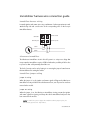
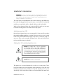
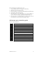
installation guide
© 2004 Directed Electronics, Inc. Vista, CA N909610 08-04
IMPORTANT! Please note that this manual was intended for US consumers
and therefore includes American phrases or words.
Bitwriter™, Code Hopping™, Directed®, Doubleguard®, ESP™, FailSafe®, Ghost Switch™, Learn Routine™,
Nite-Lite®, Nuisance Prevention Circuitry®, NPC®, Revenger®, Silent Mode™, Soft Chirp®, Stinger®, Valet®,
Vehicle Recovery System®, VRS®, and Warn Away® are all Trademarks or Registered Trademarks of Directed
Electronics, Inc., Vista, California.
2
www.directed.com
contents
warning! safety first . . . . . . . . . .5
before beginning the . . . . . . .
installation . . . . . . . . . . . . . . .6
transmitter configurations . . . . .7
transmitter functions . . . . . . . . .8
standard configuration . . . . . .8
H1 primary harness wire . . . . . .
connection guide . . . . . . . . . . . .9
primary harness wiring . . . . .
diagram . . . . . . . . . . . . . . . . .9
primary harness wiring guide .10
H2 secondary harness wire . . . .
connection guide . . . . . . . . . . . .13
secondary harness wiring . . . .
diagram . . . . . . . . . . . . . . . . .13
secondary harness wiring . . . .
guide . . . . . . . . . . . . . . . . . . .13
immobilizer harness wire . . . . .
connection guide . . . . . . . . . . . .14
immobilizer harness wiring . .14
ultrasecure immobilizer . . . . . .14
intellistart installation . . . . . . . .15
obtaining constant 12V . . . . .15
finding the 12V switched ignition
wire . . . . . . . . . . . . . . . . . . . .15
finding a (+) brake light wire .17
finding the accessory/heater .
wire . . . . . . . . . . . . . . . . . . . .17
finding the rpm input wire . . .18
finding the wait-to-start bulb wire
for diesels . . . . . . . . . . . . . . .18
H3 harness wire connection . . .
guide . . . . . . . . . . . . . . . . . . . . . .19
harness wiring diagram . . . . .19
harness wiring guide . . . . . . .20
H4 heavy gauge harness wire
.
connection guide . . . . . . . . . . . .22
heavy gauge harness wiring .
diagram . . . . . . . . . . . . . . . . .22
© 2004 directed electronics, inc.
heavy gauge harness wiring .
guide . . . . . . . . . . . . . . . . . . .22
type A: positive (+) 12-volt . .
pulse . . . . . . . . . . . . . . . . . . .24
type B: negative (-) pulse . . . .25
type C: reversing polarity . . . .26
type D: after-market actuators 27
type E: mercedes-benz and audi
(1985 & newer) . . . . . . . . . . .28
type F: one-wire system . . . . .29
type G: positive (+) multiplex .30
type H: negative (-) multiplex .31
peripheral plug-in harnesses . . .32
super bright blue led, 2-pin white
plug . . . . . . . . . . . . . . . . . . . .32
plain-view 2 valet . . . . . . . . . .32
mounting the receiver/antenna 33
arming/disarming diagnostics . .33
arming . . . . . . . . . . . . . . . . . .34
disarming . . . . . . . . . . . . . . . .34
system status chirps . . . . . . . . . .34
remote siren silencing . . . . . . . .34
multiple event total recall . . . . .35
table of zones . . . . . . . . . . . . . . .35
system features programming . .36
cliffnet wizard pro installation
software programming . . . . . .36
manual programming . . . . . .
instructions . . . . . . . . . . . . . . .36
user selectable features . . . . . .38
user selectable features . . . . .
descriptions - column one . . . .38
user selectable features . . . . .
descriptions - column two . . .39
user selectable features . . . . .
descriptions - column three . .41
installer selectable features . . .42
installer selectable features
descriptions - column one . . . .43
installer selectable features
descriptions - column two . . .43
3
installer selectable features
descriptions - column three . .45
programming notes . . . . . . . .45
fact II - false alarm control . . . .
technology . . . . . . . . . . . . . . . . .48
smart power up II . . . . . . . . . . . .48
remote control sensor disable . .48
auto-immobilization feature . . .49
auto-immobilization sequence 49
one-time valet feature . . . . . .49
shock sensor . . . . . . . . . . . . . .50
second unlock feature . . . . . .51
troubleshooting . . . . . . . . . . . . .52
wiring reference section . . . . . .53
control module connector . . .
locations . . . . . . . . . . . . . . . . .53
H4 connector . . . . . . . . . . . . .56
H3 connector . . . . . . . . . . . . .57
notes . . . . . . . . . . . . . . . . . . . . . .59
sensors . . . . . . . . . . . . . . . . . . . . .50
remote adjustable dual-zone
4
www.directed.com
warning! safety first
The following safety warnings must be observed at all times:
z
Due to the complexity of this system, installation of this product must only be performed by an authorized Clifford dealer.
z
When properly installed, this system can start the vehicle via a command signal
from the remote control transmitter. Therefore, never operate the system in an
area that does not have adequate ventilation. The following precautions are the
sole responsibility of the user; however, authorized Clifford dealers should make
the following recommendations to all users of this system:
1.
Never operate the system in an enclosed or partially enclosed area without
ventilation (such as a garage).
2.
When parking in an enclosed or partially enclosed area or when having
the vehicle serviced, the remote start system must be disabled using the
installed toggle switch.
3.
It is the user's sole responsibility to properly handle and keep out of reach
from children all remote control transmitters to assure that the system does
not unintentionally remote start the vehicle.
4.
THE USER MUST INSTALL A CARBON MONOXIDE DETECTOR IN OR
ABOUT THE LIVING AREA ADJACENT TO THE VEHICLE. ALL DOORS
LEADING FROM ADJACENT LIVING AREAS TO THE ENCLOSED OR
PARTIALLY ENCLOSED VEHICLE STORAGE AREA MUST AT ALL TIMES
REMAIN CLOSED.
z
Use of this product in a manner contrary to its intended mode of operation may
result in property damage, personal injury, or death. Except when performing
the Safety Check outlined in this installation guide, (1) Never remotely start the
vehicle with the vehicle in gear, and (2) Never remotely start the vehicle with the
keys in the ignition. The user will be responsible for having the neutral safety feature of the vehicle periodically checked, wherein the vehicle must not remotely
start while the car is in gear. This testing should be performed by an authorized
Clifford dealer in accordance with the Safety Check outlined in this product
installation guide. If the vehicle starts in gear, cease remote start operation immediately and consult with the user to fix the problem immediately.
z
After the remote start module has been installed, test the remote start module in
accordance with the Safety Check outlined in this installation guide. If the vehicle starts when performing the Neutral Safety Shutdown Circuit test, the remote
start unit has not been properly installed. The remote start module must be
removed or properly reinstalled so that the vehicle does not start in gear. All
installations must be performed by an authorized Clifford dealer.
© 2004 directed electronics, inc.
5
OPERATION OF THE REMOTE START MODULE IF THE VEHICLE STARTS IN
GEAR IS CONTRARY TO ITS INTENDED MODE OF OPERATION. OPERATING
THE REMOTE START SYSTEM UNDER THESE CONDITIONS MAY RESULT IN
PROPERTY DAMAGE OR PERSONAL INJURY. IMMEDIATELY CEASE THE USE
OF THE UNIT AND REPAIR OR DISCONNECT THE INSTALLED REMOTE START
MODULE. CLIFFORD WILL NOT BE HELD RESPONSIBLE OR PAY FOR INSTALLATION OR REINSTALLATION COSTS.
before beginning the installation
warning! This system is intended for automatic transmission, fuel-injected vehicles only. Installation in a standard
transmission vehicle maybe dangerous and is contrary to its
intended use.
z
Please read this entire installation guide before beginning the installation. The
installation of this remote start system requires interfacing with many of the vehicle’s systems. Many new vehicles use low-voltage or multiplexed systems that can
be damaged by low resistance testing devices, such as test lights and logic
probes (computer safe test lights). Test all circuits with a high quality digital multimeter before making connections.
z
Do not disconnect the battery if the vehicle has an anti-theft-coded radio. If
equipped with an air bag, avoid disconnecting the battery if possible. Many
airbag systems will display a diagnostic code through their warning lights after
they lose power. Disconnecting the battery requires this code to be erased, which
can require a trip to the dealer.
z
Remove the domelight fuse. This prevents accidentally draining the battery.
z
Roll down a window to avoid being locked out of the car.
after the installation
z
Test all functions. Refer to the "Using Your System" section of the Owner's Guide
when testing.
z
Complete the vehicle Safety Check outlined in this manual prior to reassembly.
6
www.directed.com
what is included
z
One control module
z
One four-pin immobilizer harness
z
One intellistart module
z
One 6-pin secondary harness
z
Two five-button transmitters
z
One Owner’s Guide
z
One XHF antenna/receiver with
harness
z
Two window decals
z
Warranty registration card
z
One pre-wired blue status LED
z
Quick reference card
z
One PlainView 2 Valet switch
z
Presentation envelope
z
One remote adjustable dual zone
shock sensor with harness
z
Intellistart 12-pin harness
z
Intellistart 18-pin harness
z
CliffNet interface cable
z
One 518C Neo-Siren
z
One 18-pin main wiring harness
transmitter configurations
Remote Start or
Accessory Output
Button
Silent Arm/Disarm or
Accessory Output
Button
Arm/Disarm and
Panic Button
Trunk Release or
Optional Accessory
Channel Button
Shift Button
© 2004 directed electronics, inc.
7
transmitter functions
This system uses computer-based code learning to learn the transmitter buttons. This
makes it possible to assign any transmitter button to any system function. The transmitter initially comes programmed with standard configuration, but may also be customized by an authorized dealer. The buttons in all of the instructions in this manual
correspond to a standard configuration transmitter.
standard configuration
Button
The arming, disarming, and panic function are controlled by this button.
Button
The trunk release or accessory output A is controlled by this button.
Button
Silent arm and disarm is controlled by this button.
Button
Remote start is controlled by this button.
Button, then
Button
Accessory B output is controlled by these buttons.
Button, then
Button
These buttons activate SmartWindows.
Button, then
Button
Accessory C output is controlled by these buttons.
Button twice, then
Button
These buttons active remote valet.
Button twice, then
Button
These buttons disable the sensors.
Button twice, then
Button
These buttons enter safe start mode for manual transmission vehicles and activate
Autostart mode.
8
www.directed.com
Button three times, then
Button
These buttons adjust the dual-zone shock sensor.
H1 primary harness wire connection guide
primary harness wiring diagram
H1/1
___ BLACK
H1/2
___ BROWN
H1/3
___ GRAY
H1/4
___ EMPTY
H1/5
___ GREEN/WHITE
H1/6
___ WHITE/BLUE
H1/7
___ BLUE
(-) Trunk Trigger Input - Zone 5
H1/8
___ VIOLET
(+) Door Trigger Input - Zone 4
H1/9
___ GREEN
(-) Door Trigger Input - Zone 4
H1/10
___ RED
(+) 12V Constant
H1/11
___ BROWN
Speaker Output 2
H1/12
___ WHITE/RED
H1/13
___ WHITE
Light Flash Output
H1/14
___ WHITE
Light Flash Output
H1/15
___ BLACK/WHITE
H1/16
___ RED/WHITE
H1/17
___ ORANGE
H1/18
___ EMPTY
© 2004 directed electronics, inc.
Ground
Speaker Output 1
(-) Hood Trigger Input Zone 6
Not Used
(-) Normally Closed Input - Zone 6
(-) Accessory B Output (200mA)
Light Flash Input
Dome Light Supervision Output 30
(-) Accessory Output A (200mA)
Ground When Armed (500mA)
Not Used
9
primary harness wiring guide
This guide describes in detail the connection of each wire. Also included are possible
applications of each wire. This system was designed with the ultimate in flexibility and
security in mind. Many of the wires have more than one possible function. Please read
the instructions carefully to ensure a thorough understanding of this unit and how it
operates.
h1/1 black ground
Connect the BLACK wire to a clean, paint-free sheet metal location (driver’s kick panel)
using a factory bolt that does NOT have any vehicle component grounds attached to
it. A screw should only be used in conjunction with a two-sided lock washer. Under
dash brackets and door sheet metal are not acceptable ground points. It is recommended that all security components be grounded at the same location.
h1/2 and h1/11 brown speaker outputs
Connect the BROWN output wires to the BROWN wires of the 518C Neo Siren.
h1/3 gray (-) hood input zone 6
Connect this wire to the hood pin. If the hood is open when the alarm is armed, this
wire will trigger the siren. Use either this wire (preferred) or the wire from the
Intellistart module, but not both.
10
www.directed.com
h1/5 green/white (-) normally closed zone 6
This wire will trigger the alarm if it looses its normally closed ground. Remove this wire
from the ground wire and attach it to a normally grounded item you wish to protect
such as the back of your stereo.
h1/6 white/blue (-) accessory b output (200mA)
This wire produces a 200mA output when activated by the remote control and can be
used to operate a variety of accessories. All accessory outputs can be programmed to
different types of outputs. Please see Programming Note #6.
h1/7 blue (-) trunk trigger input - zone 5
This input will respond to a negative input with an instant trigger. Connect to (-) trunk
pins and it will report on zone 5. It can also be used with Directed single-stage sensors.
h1/8 violet (+) door trigger input - zone 4
Connect the violet wire to a wire that shows (+)12V when any door is opened. This
wire will report zone 4.
h1/9 green (-) door trigger input - zone 4
Most vehicles use negative door trigger circuits. Connect the GREEN wire to a wire
showing ground when any door is opened. When connecting to newer model vehicles
there is generally a need to use individual door triggers. This wire will report Zone 4.
NOTE: If using a door trigger wire that has a delay, the installer-selectable programming grid or the Cliffnet Wizard can be used to turn the door ajar warning off.
h1/10 red (+) 12v constant
Before connecting the RED wire, remove the supplied fuse. Connect to the battery positive terminal (be sure to use the supplied fuse holder and a 5 amp fuse) or the constant (+) 12V supply to the vehicle fusebox.
© 2004 directed electronics, inc.
11
h1/12 white/red light flash input
IMPORTANT! Always confirm light fash polarity before connecting H1/H12 or damage to the vehicle lighting system could occur.
This wire is the input for the on-board dual light flash relay. If the vehicle has positive
parking light activation wires, connect this wire to a constant (+) 12V source that is
fused at 15A or higher (be sure to use the supplied fuse holder and a 15 amp fuse).
If the vehicle parking light activation wire is negative, connect this wire to a chassis
ground location.
h1/13 and h1/14 white parking light output
IMPORTANT! The polarity of this wire is determined by the connection of the H1/12
light flash input wire.
These wires are the output of an on-board dual make relay and the polarity is determined by the connection of the H1/12 light flash input wire. Connect these to the
wires in the vehicle that control the parking lights. The dual outputs are designed for
European vehicles with isolated parking light systems. If the vehicle’s parking lights are
controlled by a single wire, connect both WHITE wires to it.
h1/15 black/white dome light supervision output
Connect the H1/15 BLACK/WHITE wire to the vehicle domelight circuit trigger wire.
h1/16 red/white accessory a output
When the system receives the code controlling the accessory output, this wire will supply an output as long as the transmission continues. This is often used to operate a
trunk/hatch release or other relay-driven function. All accessory outputs can be programmed to different types of outputs. Please see Programming Note #6.
IMPORTANT! Never use this wire to drive anything but a relay or a low-current input!
The transistorized output can only supply 200 mA of current. Connecting directly to a
solenoid, motor, or other high-current device will cause it to fail.
12
www.directed.com
h1/17 orange ground when armed
This wire provides a (-) ground output as long as the system is armed and will cease
when the system is disarmed. This output can be used for an additional immobilizer
relay or to control additional accessories such as window automation, voice modules,
or pagers.
H2 secondary harness wire connection
guide
secondary harness wiring diagram
H2/1
___ YELLOW/WHITE
H2/2
___ EMPTY
H2/3
___ BLACK/WHITE
H2/4
___ EMPTY
Not Used
H2/5
___ EMPTY
Not Used
H2/6
___ BLUE/WHITE
(-) Horn Honk Output (200 mA)
Not Used
Domelight Supervision Input (87)
Second Unlock Output (200 mA)
secondary harness wiring guide
NOTE: For further description of the H2/1 to H2/6 wires, please refer to the Door
Lock Harness Wire Connection Guide section.
h2/1 yellow/white (-) horn honk output (200mA)
This wire is a low current output (200mA) for the horn to sound when the system has
been violated.
h2/3 black/white domelight supervision input (87)
This wire determines the output of the BLACK/WHITE H1/15 wire on the main 18-pin
harness. If the vehicle has a negative domelight circuit, ground this wire; if the vehicle has a positive domelight circuit, attach this wire to a 12 volt constant source.
h2/6 blue/white second unlock output (200mA)
This wire produces a (-) 200mA output for progressive locks in which the driver door
unlocks first and the remaining locks unlock with a second press of the unlock button.
© 2004 directed electronics, inc.
13
immobilizer harness wire connection guide
immobilizer harness wiring
Locate the ignition and starter wires using a multimeter. Cut the appropriate wire and
attach the key side and car side wires to the corresponding wires on the four-pin
immobilizer harness.
Starter Side
Ignition Car Side
Starter Key Side
Ignition Key Side
Starter
Ignition
x
CUT
x
CUT
ultrasecure immobilizer
The UltraSecure immobilizer circuit in this G5 system is a unique new design that
incorporates the immobilizer security of Clifford without the possibility of failure due
to power loss that could potentially strand the user.
The level of security can be set by leaving in or removing the jumper located next to
the immobilizer wires exiting the module.
immobilizer jumper setting
jumper in setting
When the jumper is in, the ignition and starter signal will bypass the UltraSecure
immobilizer circuitry and allow the vehicle start and run, even if power has not been
restored to the module.
jumper out setting
When the jumper is out, the UltraSecure immobilizer circuitry prevents the ignition
and starter signal from passing and keeps the vehicle immobilized until power has
been restored to the module.
NOTE: In order for the system to bypass the immobilizer with the jumper in place, the
unit must have ground on the 18-pin harness.
14
www.directed.com
intellistart installation
IMPORTANT! Do not use any testing tool other than a digital multi-meter to prevent
costly damage to the vehicle. Use of a test light may cause grounding of sensitive electrical components that can damage the on-board vehicle computer and processors
resulting in substantial cost for replacement.
The control module and the Intellistart module communicate through the CliffNet interface cable, when plugged into their respective ports on each module. Ensure that both
modules are mounted in the vehicle so that this cable can reach both modules.
When you have determined where each component will be located, your next step is
to find the connecting wires in the vehicle for the security system.
obtaining constant 12V
Remove the two 30 amp fuses prior to connecting to the 12V wires and do not replace
them until the intellistart installation is complete. These wires are the source of current
for all the circuits the IntelliStart will energize. They must be connected to a high current source. These can be connected to the battery or the 12V power feed to the ignition key switch (the battery is preferred).
finding the 12V switched ignition wire
warning! On vehicles with air bags or supplemental
restraint systems (SRS) you may notice a bright yellow
tube with small wires in it marked SRS underneath the
steering column near the key cylinder. DO NOT tamper or unplug these for any reason to prevent costly damages to your vehicle or personal injury. Tampering may
cause unintended deployment of airbags.
warning! Make sure the car is not in gear.
The ignition wire is powered when the key is in the run or start position. This is
because the ignition wire powers the ignition system (spark plugs, coil) as well as the
fuel delivery system (fuel pump, fuel injection computer). Accessory wires lose power
when the key is in the start position to make more current available to the starter motor.
© 2004 directed electronics, inc.
15
How to find (+)12V ignition with your multimeter:
1.
Set to DCV or DC voltage (12V or 20V is fine).
2.
Attach the (-) probe of the meter to chassis ground.
3.
Probe the wire you suspect of being the ignition wire. The steering column harness or ignition switch harness is an excellent place to find this wire.
4.
Turn the ignition key switch to the run position. If your meter reads (+)12V, go to
the next step. If it doesn’t, probe another wire.
5.
Now turn the key to the start position. The meter display should stay steady, not
dropping by more than a few tenths of a volt. If it drops close to or all the way to
zero, go back to Step 3. If it stays steady at (+)12V, you have found an ignition wire.
finding the starter wire
The starter wire provides 12V directly to the starter or to a relay controlling starter. In
some vehicles, it is necessary to power a cold start circuit. A cold start circuit will test
exactly like a starter circuit, but it does not control the starter. Instead, the cold start
circuit is used to prime the fuel injection system for starting when the vehicle is cold.
How to find the starter wire with your multimeter:
1.
Set to DCV or DC voltage (12V or 20V is fine).
2.
Attach the (-) probe of the meter to chassis ground.
3.
Probe the wire you suspect of being the starter wire. The steering column is an
excellent place to find this wire. Remember you do not need to interrupt the
starter at the same point you test it. Hiding your optional starter kill relay and
connections is always recommended.
4.
Turn the ignition key switch to the start position. Make sure the car is not in gear!
If your meter reads (+)12V, go to the next step. If it doesn’t, probe another wire.
5.
Cut the wire you suspect of being the starter wire.
6.
Attempt to start the car. If the starter engages, reconnect it and go back to Step
3. If the starter does not turn over, you have the right wire.
16
www.directed.com
finding a (+) brake light wire
Most vehicles use a (+) brake light circuit. The (+) brake light wire is often found near
the brake pedal.
How to find a (+) brake light flash wire with your multimeter:
1.
Set to DCV or DC voltage (12V or 20V is fine).
2.
Attach the (-) probe of the meter to chassis ground.
3.
Probe the wire you suspect of being the brake light wire.
4.
Press the brake pedal. If your meter shows (+)12V, release the pedal and make
sure it goes back to zero.
5.
If it does return to zero, this is the correct brake wire.
finding the accessory/heater wire
An accessory/heater wire will show +12V when the key is in the accessory and run
positions. It will not show +12V during the cranking cycle. There will often be more
than one accessory wire in the ignition harness. The correct accessory wire will power
the vehicle's climate control system. Some vehicles may have separate wires for the
blower motor and the air conditioning compressor. In such cases, it will be necessary
to add a relay to power the second accessory wire.
© 2004 directed electronics, inc.
17
finding the rpm input wire
To test for a tachometer wire, a multimeter capable of testing AC voltage must be used.
The tachometer wire will show between 1V and 6V AC. In multi-coil ignition systems,
the system can learn individual coil wires. Individual coil wires in a multi-coil ignition
system will register lower amounts of AC voltage. Also, if necessary, the system can
use a fuel injector control wire for engine speed sensing. Common locations for a
tachometer wire are the ignition coil itself, the back of the gauges, engine computers,
and automatic transmission computers.
warning! On vehicles with air bags or supplemental
restraint systems (SRS) you may notice a bright yellow
tube with small wires in it marked SRS underneath the
steering column near the key cylinder. DO NOT tamper or unplug these for any reason to prevent costly damages to your vehicle or personal injury. Tampering may
cause unintended deployment of airbags, resulting in
injury.
IMPORTANT! Do not use any testing tool other than a digital multi-meter to prevent
costly damage to the vehicle. Use of a test light may cause grounding of sensitive electrical components that can damage the on-board vehicle computer and processors
resulting in substantial cost for replacement.
How to find a tachometer wire with your multimeter:
1.
Set to ACV or AC voltage (12V or 20V is fine).
2.
Attach the (-) probe of the meter to chassis ground.
3.
Start and run the vehicle.
4.
Probe the wire you suspect of being the tachometer wire with the red probe of
the meter.
5.
If this is the correct wire the meter will read between 1V and 6V and fluctuate
with the RPM of the motor.
finding the wait-to-start bulb wire for diesels
In diesel vehicles it is necessary to interface with the wire that turns on the WAIT TO
START light in the dashboard. This wire illuminates the bulb until the vehicle’s glow
plugs are properly heated. When the light goes out the vehicle can be started. This
wire is always available at the connector leading to the bulb in the dashboard. It can
also be found at the Engine Control Module (ECM) in many vehicles.
18
www.directed.com
To test and determine the polarity of this wire:
1.
Set your multimeter to DCV or DC voltage (12 or 20V is fine).
2.
Attach the (+) probe of the meter to (+)12V.
3.
Probe the wire that you suspect leads to the bulb with the (-) probe of the meter.
4.
Turn the ignition switch to the ON position.
5.
If the meter indicates 12 volts until the light goes out you have isolated the correct wire and the wire's polarity is negative (ground while the bulb is on).
6.
If the meter reads zero volts until the light goes out and then reads 12 volts, you
have isolated the correct wire and the wire's polarity is positive.
H3 harness wire connection guide
harness wiring diagram
H3/1
___ BLACK/GREEN
Automatic Transmission Mode (-)
H3/2
___ VIOLET/WHITE
Remote Start Smart Lock
H3/3
___ WHITE/BLACK
Hood Trigger Input (-)
H3/4
___ WHITE/VIOLET
Factory Alarm Disarm
H3/5
___ RED
H3/6
___ BLUE/ORANGE
H3/7
___ BLACK
H3/8
___ BLUE/BLACK
H3/9
___ BLUE/YELLOW.
H3/10
___ BLUE/GREEN
H3/11
___ BLUE/WHITE
Brake Light Input (+)
H3/12
___ BLACK/GRAY
RPM Input
© 2004 directed electronics, inc.
Battery Positve (5-amp fuse) 12V (+) Input
Third Ignition Trigger
Ground
Negative Switching Wait-To-Start Bulb (Diesel)
Positive Switching Wait-To-Start Bulb (Diesel)
Shut Down (+)
19
harness wiring guide
h3/1 black/green automatic transmission mode
warning! This system is intended for automatic transmission, fuel-injected vehicles only. Installation in a standard
transmission vehicle maybe dangerous and is contrary to its
intended use.
This wire needs to be grounded when IntelliStart is installed.
h3/2 violet/white remote start smart lock
This wire produces a 200mA negative output when the remote start has been activated locking the doors during the remote start sequence. Connect this to the lock wire
of the vehicle, only if the doors must be unlocked to remote start the vehicle.
h3/3 white/black hood input
This wire will shut down the remote start if the hood is opened during a remote start
sequence. Connect this to the hood pin switch wire that shows ground when the hood
is opened. Use this wire or, preferably, the H1/3 wire from the control module. Do not
use both wires (H1/3 and H3/3).
h3/4 white/violet factory alarm disarm
This wire will produce a 200mA output prior to a remote start sequence. Connect this
wire to the factory alarm disarm wire in the vehicle.
h3/5 red battery Positive (5-amp fuse) 12V (+) input
Connect this wire to a constant (+) 12V source.
h3/6 blue/orange third ignition trigger
This wire will trigger an additional relay for a third ignition output. When needed,
connect this wire to an optional relay.
h3/7 black ground
h3/8 blue/black (-) and h3/9 (+) blue/yellow diesel wait to start
There are two methods for interfacing the remote engine starting on diesel engines.
You can either interface via the “Wait-to-Start” light which will trigger the starter when
the light turns off, or you can use the built-in 20 second timer which cranks the engine
20 seconds after the remote start command is received.
20
www.directed.com
Using the 20 second delay: Using the Installer-Programming for the system, change
the engine setting to “Diesel Engine,” or use the CliffNet Wizard Pro installation software to program the system. The CliffNet Wizard Pro will also allow you to customize
the delay to an interval other than 20 seconds.
h3/10 blue/green (+) shut down
1.
When the intellistart is programmed to Automatic transmission mode (H3/1
black/green is grounded), then connect the H3/10 blue/green wire to the vehicles back up light wire. This wire should show +12V when the shifter is in
reverse, and show no voltage or ground when NOT in reverse.
2.
When the intellistart is programmed to Manual transmission mode (H3/1
black/green is NOT grounded) connect the H3/10 blue/green wire to the parking brake indicator wire. The wire should show ground when the parking brake
is set, and +12V when the parking brake is NOT set.
h3/11 brake light input (+)
The IntelliStart monitors the brake light to prevent an unauthorized driver from driving the car. The brake light input wire MUST be connected and brake light must be in
working condition. This connection is not necessary if the alarm is already connected
to the brake with the H2/11 wire on the main control module (preferred).
h3/12 black/gray rpm input
This wire monitors the RPM of the vehicle during remote start sequence. Connect this
wire to the vehicle coil’s negative side or the non-common fuel injector wire.
© 2004 directed electronics, inc.
21
H4 heavy gauge harness wire connection
guide
heavy gauge harness wiring diagram
H4/1
___ ORANGE
H4/2
___ RED
H4/3
___ ORANGE/GRAY
Ignition 2 Output
H4/4
___ GREEN/BLUE
Ignition 1 Output
H4/5
___ EMPTY
H4/6
___ GRAY/ORANGE
H4/7
___ WHITE/BLUE
H4/8
___ RED
H4/9
___ GRAY.
Accessory Output
Battery Positive (30-amp fuse) 12V (+) Input
Not Used
Heater 2 Output
Starter Output
Battery Poisitve (30-amp fuse) 12V (+) Input
Heater/Air Conditioner 1 Output
heavy gauge harness wiring guide
All except the red heavy gauge wires leading from the relay satellite are used to energize high current circuits in the vehicle. It is crucial that these connections are made
correctly so that they are capable of handling the current demands. For this reason,
scotch locks, T-taps and other such connectors should not be used.
h4/1 orange (+) accessory output (retained)
Connect this wire to the accessory wire in the vehicle that powers the accessories in
the vehicle. This wire will retain power for 10 minutes after the ignition key is turned
off, or when a door is opened.
h4/2 red (+)12V input
NOTE: If the factory supplies two separate (+) 12V feeds to the ignition switch, connect one RED wire of the intellistart to each feed at the switch.
Remove the 30 amp fuse prior to connecting to the 12V wire and do not replace until
the intellistart installation is complete. This wire is the source of current for all the circuits the IntelliStart will energize. It must be connected to a high current source. It can
be connected to the battery or the 12V power feed to the ignition key switch (the battery is preferred).
22
www.directed.com
h4/3 orange/gray (+) output to second ignition circuit
Connect this wire to the second ignition wire in the vehicle.
h4/4 green/blue (+) ignition output
Connect this wire to the ignition wire in the vehicle.
h4/6 gray/orange heater 2 output (retained)
Connect this wire to the second accessory wire in the vehicle that powers the climate
control system. This wire will retain power for 10 minutes after the ignition key is
turned off, or until a door is opened.
h4/7 white/blue (+) starter output
Connect this wire to the starter wire in the vehicle.
h4/8 red (+)12V input
NOTE: If the factory supplies two separate (+) 12V feeds to the ignition switch, connect one RED wire of the satellite to each feed at the switch.
Remove the 30 amp fuse prior to connecting this wire and do not replace them until
the satellite has been plugged into the control module. This wire is the source of current for all the circuits the relay satellite will energize. It must be connected to a high
current source. Since the factory supplies (+) 12V to the key switch that is used to
operate the motor, it is recommended that this wire be connected there.
h4/9 gray heater/air conditioner 1 output (retained)
Connect this wire to the accessory wire in the vehicle that powers the climate control
system. This wire will retain power for 5 minutes after the ignition key is turned off, or
until a door is opened.
© 2004 directed electronics, inc.
23
door lock harness wire connection guide
H3/1
___ GREEN
(-) Lock, (+) Unlock Output
H3/2
___ EMPTY
(+) 12V Protected, Low Current for 451M
H3/3
___ BLUE
(-) Unlock, (-) Lock Output
IMPORTANT! The door lock outputs are low current and should not be attached directly to any high-current device; they are only to be used to activate relays
type A: positive (+) 12-volt pulse
The system can control Type A door locks directly, with no additional parts. The switch
will have three wires on it; one will test (+)12 volt constantly. The others will alternately pulse (+)12 volt when the switch is pressed to the lock or unlock position.
If you cannot get to the switch, and you find a set of wires that pulse (+)12 volt alternately on lock and unlock, make sure that it is not a Type C direct-wire system.
Cut the wire that pulses (+)12 volt on lock, and then operate the switch to unlock.
z
If all doors unlock, the vehicle uses type A system.
z
If you lose all door lock operation in both directions, you are operating the master switch in a Type C system.
z
If you lose all door lock operation of one or more, but not all motors, and other
doors still work, you have cut a wire leading directly to one or more motors. You
must instead find the actual wires leading to the switch.
IMPORTANT! Remember that these wires' functions reverse between Type A and Type
B.
24
www.directed.com
type B: negative (-) pulse
This system is common in many Toyotas, Nissans, Hondas, and Saturns, as well as
Fords with keyless entry systems (some other Fords also use Type B). Most European
Ford vehicles with (-) negative pulse locking are high current so a 451M or 2 relays
need to be used.
The switch will have three wires on it, and one wire will test ground all the time. One
wire will pulse negative (-) when the switch locks the doors, and the other wire will
pulse negative (-) when the switch unlocks the doors. This type of system is difficult to
mistake for any other type.
IMPORTANT! Remember that these wires' functions reverse between Type A and Type
B.
© 2004 directed electronics, inc.
25
type C: reversing polarity
Interfacing with a reversing polarity system requires either two relays or one DEI
451M (not included). It is critical to identify the proper wires and locate the master
switch to interface the door locks properly. Locate wires that show voltage on lock and
unlock. Cut one of the suspected wires and check operation of the locks from both
switches. If one switch loses operation in both directions and the other switch operates
in one direction only, you have located one of the target wires. The switch that lost all
operation is the master switch. If one switch works in both directions and the other
switch works in only one direction, you have a Type A system. If both switches still
operate, but one or more doors has stopped responding entirely, you have cut a motor
lead. Reconnect it and continue to test for another wire. Once both wires have been
located and the master switch has been identified, cut both wires and interface as
shown in the following diagram.
IMPORTANT! If these wires are not connected properly, you will send (+) 12 volt
directly to (-) ground, possibly damaging the alarm or the factory switch.
IMPORTANT! Do not connect the outputs of the alarm directly to the actuator.
26
www.directed.com
type D: after-market actuators
In order for this system to control one or more after-market actuators, a DEI 451M or
two relays (optional) are required. Vehicles without factory power door locks require
the installation of one actuator per door. This requires mounting the door lock actuator inside the door. Other vehicles may only require one actuator installed in the driver's door if all door locks are operated when the driver's lock is used.
The fuse used on 12 volt inputs should be 7.5A per motor installed in the vehicle.
© 2004 directed electronics, inc.
27
type E: mercedes-benz and audi (1985 & newer)
Type E door locks are controlled by an electrically activated vacuum pump. Some
Mercedes and Audis use a Type D system. Test by locking doors from the passenger
key cylinder. If all the doors lock, the vehicle's door lock system can be controlled with
just two relays (optional). The control wire can be found in either kick panel and will
show (+)12 volt when doors are unlocked and (-) ground when doors are locked.
To interface see diagram below. The system must be programmed for 3.5 second door
lock pulses up to 1993 and 1 second pulse 1994 or newer.
28
www.directed.com
type F: one-wire system
Type F door locks usually require a negative pulse to unlock and cutting the wire to
lock the door. In some vehicles, these functions are reversed. Type F door locks are
found in late-model Nissan Sentras, some Nissan 240SX, and Nissan 300ZX 1992up. They are also found in some Mazda MPVs, some Mitsubishis, and Lotus.
One relay (optional) is used to interface to this type of system as follows:
© 2004 directed electronics, inc.
29
type G: positive (+) multiplex
The door lock switch or door key cylinder may contain either one or two resistors.
When interfacing with this type of door lock system, two relays or a DEI 451M must
be used.
Single-Resistor Type
If one resistor is used in the door lock switch/key cylinder, the wire will pulse (+)12
volt in one direction and less than (+)12 volt when operated in the opposite direction.
Two-Resistor Type
If two resistors are used in the factory door lock switch/key cylinder, the switch/key
cylinder will read less than (+)12 volt in both directions.
30
www.directed.com
type H: negative (-) multiplex
The door lock switch or door key cylinder may contain either one or two resistors.
When interfacing with this type of door lock system, two relays or a DEI 451M must
be used.
Single-Resistor Type
If one resistor is used in the door lock switch/key cylinder, the wire will pulse ground
in one direction and resistance to ground when operated in the opposite direction.
Two-Resistor Type
If two resistors are used in the factory door lock switch/key cylinder, the door lock
switch/key cylinder will read resistance to ground in both directions.
© 2003 directed electronics, inc.
31
peripheral plug-in harnesses
super bright blue led, 2-pin white plug
The super bright LED operates at (+) 2V DC. Make sure the LED wires are not shorted to ground as the LED will be damaged. Multiple LEDs can be used, but they must
be wired in series. The LED can be top-mounted or flush-mounted. If top-loading the
LED with a bezel, the LED fits into a 5/16-inch mounting hole. If flush-mounting the
LED from the back of a panel, drill a mounting hole using a 17/64-inch drill bit. Be
sure to check for clearance prior to drilling the mounting hole.
plain-view 2 valet
The Valet/Program switch should be accessible from the driver’s seat. It plugs into the
blue port on the side of the unit. Consider how the switch will be used before choosing a mounting location. Check for rear clearance before drilling a 9/32-inch hole
and mounting the switch.
32
www.directed.com
mounting the receiver/antenna
NOTE: Be sure not to bundle excess cable as this will reduce the range.
The receiver/antenna position should be discussed with the vehicle owner prior to
installation since the antenna may be visible to the vehicle’s operator.
The best position to locate the receiver/antenna is centered high on either the front or
rear windshield. For optimal range, the antenna should be mounted vertically. It can
be mounted horizontally in relation to the windshield or under the dashboard away
from metal, but range will be reduced. Metallic window tint can also affect range, so
this should be a consideration when determining the mounting location.
After determining the best mounting location, follow these steps:
1.
Clean the mounting area with a quality glass cleaner or alcohol to remove any
dirt or residue.
2.
Plug the receiver/antenna cable into the receiver/antenna.
3.
Mount the receiver/antenna with double-sided tape.
4.
Route the receiver/antenna cable down the window pillar to the control module
and plug the cable into the control module.
arming/disarming diagnostics
The systems microprocessor monitors and reports all active and violated zones when
arming and disarming the system.
© 2004 directed electronics, inc.
33
arming
Zones that are triggered at the time the system is armed are reported by an additional set of status chirps called Malfunction AutoBypass. The specific zone bypassed is
then reported by the LED. For more zone information, refer to Table of Zones section
of this guide.
disarming
If a zone is triggered, three disarm chirps will sound. The specific zone that was triggered is then reported by the LED when the ignition is turned on. For more zone information, refer to the Table of Zones section of this guide.
system status chirps
Action
No. of Chirps
Arm
2
Description
System armed.
Arm
4
System armed with hood or
trunk bypass zones 5 and 6.
Arm
2 (5-second pause) 4
System armed with door bypass zone 4
Arm
2 (10-second pause) 4
System armed with sensor active
and bypassed zones 1, 3, and 8.
Disarm
1
System disarmed.
Disarm
3
System disarmed with zone violation
remote siren silencing
While the siren is sounding, press the arm/disarm button once to silence the siren but
leave the system in the armed state. To disarm the system, press the arm/disarm button a second time.
NOTE: If the remote control battery is low, the siren will generate a single low pitched
chirp when disarming.
34
www.directed.com
multiple event total recall
This will report the last eight system triggers.
1.
Press and hold
of the PlainView 2 Valet switch.
2.
While still holding
3.
The LED will start to blink to indicate the most recent trigger and proceed down
to the eighth trigger. If fewer than eight triggers are stored in memory, the LED
will blink continuously until the system is armed/disarmed or the ignition is turned
on. For more information, please refer to the Table of Zones section of this guide.
, arm and disarm the system, then release the button.
table of zones
When using the diagnostic functions, use the Table of Zones to see which input has
triggered the system. It is also helpful in deciding which input to use when connecting
optional sensors and switches.
Zone - Number of
LED Flashes
Trigger type
Input description
1
Data
Dual Zone Shock Sensor
N2OTE: The Warning N/A
Zone response does not report on the LED.
3
Mux 1
Sensor Input
4
Instant
Door Pin Input
5
Instant
Trunk Pin Input
6
Instant
Hood Pin Input
7
Instant
Ignition Input
8
Mux 2
Sensor Input
9
N/A
10
N/A
© 2004 directed electronics, inc.
Alarm power reset
35
system features programming
This system has many features that can be programmed to accommodate the user's
personal preferences and make system installation easier. They are listed in two programming grids on the following pages. Many features have default settings that have
been programmed at the factory and are indicated in bold type.
The User Selectable Features grid allows the user and installer to change operational
features through the PlainView 2 Valet. The Installer Selectable Features grid allows
the installer to change input/output functions of the system to integrate with the vehicle’s specific characteristics.
cliffnet wizard pro installation software programming
Cliffnet Wizard Pro provides access to all available system features and some that are
not available when manually programming with the Valet switch. Cliffnet Wizard Pro
is compatible with Microsoft Windows 95/98/2000/ME/XP/NT so most programming operations can be accomplished by pointing and clicking with a mouse. This
eliminates the need for programming grids and lengthy programming sequences. For
a complete guide to system programming using the Cliffnet Wizard Pro refer to the
Cliffnet Wizard help menu.
manual programming instructions
Be sure to document changes by taking note of all feature changes made in programming mode.
To enter the User Selectable Features programming:
1.
Ignition on - Turn the ignition to the run position or start the engine.
2.
Enter PIN - Enter the factory preset PIN code of 2 by pressing
PlainView 2 Valet switch twice, then
once.
on the
NOTE: If the factory preset PIN has been changed, the new PIN must be entered.
3.
Hold/Chirp/Release - After entering the PIN code, press and hold
until a
chirp is heard and the LED turns on, then release the button. You have now
entered the feature selection position of the User Selectable Features grid.
4.
Column select - Press
the same number of times as the desired column. After
a pause the siren will chirp the same number of times as the selected column for
confirmation.
5.
Feature select - Press
the same number of times as the desired feature. The
siren will chirp with each press. The feature can now be changed using the
remote control.
36
www.directed.com
6.
Feature change - Press the arm/disarm button on the transmitter. If the system
chirps once, the feature has just turned off; if the system chips twice, the feature
has just turned on. If the feature has more than two settings, continue pressing
the arm/disarm button on the transmitter to toggle through the settings.
To advance to the next feature in the same column, press
the same number
of times as the desired feature within 60 seconds; to change a feature in a
different column begin at step 4 by entering the column number first and then
the row number.
NOTE: Refer to the Feature Descriptions sections of this guide for important notes and
descriptions of the system features and programming.
7.
Exit programming - To exit programming mode turn the ignition off or wait 60
seconds without pressing the PlainView 2 Valet switch. The siren will chirp three
times to indicate programming mode has been exited.
© 2004 directed electronics, inc.
37
user selectable features
Then
Press
First
Press
Add new remote
(autolearn)
Set PIN code
(default = 2)
New remote learn
arm/disarm only
Auto (passive)
arm off/on
Select siren
sounds
New remote learn
accessory A channel
Chirps
off/on/quiet
FACT II off/on
New remote learn
accessory B channel
Auto lock
off/ignition/rpm
Remote valet
off/on
New remote learn
silent mode
Auto unlock
off/ignition
Entry delay off/on
New remote learn
remote valet
Auto (passive)
arm and lock
off/on
Siren duration
30/60/90
Reset to default
(except transmitter
and valet code)
Panic on/off
New remote learn
remote start*
Second unlock
off/on
Autostart setting*
(off/battery only/
temp only/
battery and temp)
Not used
Not used
*
**
New remote learn
window down/vent**
Not used
Clear all remotes
This feature is only available with optional IntelliStart connected.
This feature is only available with optional SmartWindows connected.
user selectable features descriptions - column one
add new remote (only applicable with Radar 2 remote)
z
Auto-learn new remote controls to the system in the standard button configuration. For more information, see programming note #1.
auto (passive) arm - off/on
z
Off: The transmitter must be used to arm the system.
z
On: When the system sees the ignition turn off and the last protected entry (door,
hood, or trunk) close, it will begin a 30-second countdown before arming itself.
After the first five seconds, you will hear two chirps and the lights will flash. The
system will arm 25 seconds later.
38
www.directed.com
chirps - off/on/quiet
z
Off: Chirps will not sound when arming/disarming the system.
z
On: Chirps will sound when arming/disarming the system.
z
Quiet: Chirps will sound when arming/disarming the system but at a lower
volume than normal.
auto lock - off/ignition/rpm
z
Off: The doors will not lock automatically.
z
Ignition: The doors will automatically lock three seconds after the ignition is
turned on unless a door is open at that time.
z
Rpm: The doors will lock when the system sees the engine reach a preprogrammed RPM. The H1/4 VIOLET/BLACK or Intellistart must be connected.
auto unlock - off/ignition
z
Off: The doors will not automatically unlock when the ignition is turned off
z
Ignition: The doors will automatically unlock as soon as the ignition is turned off.
auto (passive) arm lock - off/on
z
Off: The doors will not lock when the system passively arms.
z
On: The doors will lock when the system passively arms. This feature only applies
when passive arming is programmed on.
siren duration - 30/60/90
z
The system will sound the alarm for the programmed duration (30/60/90
seconds) during an alarm trigger or when the system is put into panic mode.
second unlock - off/on
z
Off: Second unlock output is pulsed at the same time as the unlock output when
the system is disarmed.
z
On: Second unlock output is active when the arm/disarm button is pressed within 10 seconds of disarming the system.
user selectable features descriptions - column two
set pin code
z
This feature allows the setting of the user's personal PIN code. For more information, see programming note #5. The factory default PIN code is 2.
© 2004 directed electronics, inc.
39
select siren sounds
z
The individual sounds the siren produces during an full trigger alarm can be
customized for owner recognition of an alarm trigger. For more information, see
programming note #3.
fact II off/on
z
Off: The alarm will respond to zone inputs indefinitely without bypassing.
z
On: The alarm will bypass for 60 minutes zones that are triggered three times
within a one hour period.
remote valet off/on
z
Off: The alarm can not be put into valet mode with the remote control.
z
On: The alarm can be put into valet mode with the remote control.
entry delay off/on
z
Off: There is no entry delay when the system has passively armed. The system
will trigger instantly when a door is opened.
z
On: If the system has passively armed, it will not trigger for 15 seconds after a
door is opened allowing the user to enter the vehicle and disarm the system via
the PlainView 2 Valet switch.
reset to default settings
z
All system settings (except PIN and remote programming) in the User
Programming grid will be reset to their default factory setting as indicated in
bold lettering.
z
Press the arm/disarm button of the TX; the siren will chirp twice as confirmation.
panic off/on
z
Off: The panic feature is not available.
z
On: The panic feature is available.
auto start setting - off/battery only/temp only/battery and temp
z
This feature is only available with the IntelliStart option.
z
Off: The vehicle will not autostart.
z
Battery: The vehicle will only autostart when the car battery gets low.
z
Temperature: The vehicle will only autostart at a preset low temperature.
z
Battery and temperature: The vehicle will autostart with a low car battery or low
temperature.
NOTE: Temperature and battery calibration and settings can be made only with the
Cliffnet Wizard.
40
www.directed.com
user selectable features descriptions - column three
The features in this column pertain to programming individual transmitter channels in
custom configurations. Following is an explanation of the features. Program the individual transmitter channels following the instructions in programming note #2.
arm/disarm only
z
The remote control channel programmed into this feature will arm/disarm the
system only.
NOTE: When programming a new remote control to custom configuration a channel
must first be programmed to this feature before programming the remaining channels.
accessory a output
z
The transmitter channel programmed into this feature will activate the accessory
output.
accessory b output
z
The transmitter channel programmed into this feature will activate the accessory
output.
silent mode
z
The transmitter channel programmed into this feature will arm/disarm the
system, but the siren will not chirp.
remote valet
z
The transmitter channel programmed into this feature will make the system
enter/exit valet mode.
remote start
z
This feature is only available with IntelliStart connected
z
The transmitter channel programmed into this feature will activate or shut down
the Intellistart remote start system.
window control
z
This feature is only available with SmartWindows connected
z
The transmitter channel programmed into this feature will activate the vent or roll
down feature of the SmartWindows system.
© 2004 directed electronics, inc.
41
clear all remotes
z
This feature will erase all remote codes from the system memory. This feature is
convenient for erasing any transmitters that have been lost, stolen, or incorrectly programmed into the system.
z
After entering this feature press any button on the transmitter; the siren will chirp
to indicate that all transmitters have been erased from memory.
installer selectable features
To enter the Installer Selectable Features grid follow the instructions for the User
Selectable Features with the exception of step 4. Perform step 4 as described below
to enter the Installer Selectable Features grid.
Hold/Chirp/Release - After entering the PIN code, press and hold
until the siren
chirps once. Continue holding for approximately 10 seconds until the siren chirps
three times, then release the button. You have now entered the feature selection position of the Installer Selectable Features grid.
*
P1 = Pulsed channel output is disabled with the ignition on or the alarm is
armed.
** P2 = Pulsed channel output works anytime.
*** Only with optional IntelliStart connected.
**** Only with optional SmartWindows connected.
**** Remote adjustable sensor port: The 3-pin proximity/shock port can be
used for either the proximity sensor or the remote adjustable magnetic resonance impact sensor. This programming branch is used to choose the sen42
www.directed.com
sor software. The proximity sensor is the default 2 chirp setting. The impact
sensor is the 1 chirp setting.
installer selectable features descriptions - column one
lock pulse single/double
z
Single: One door lock pulse will be output when the system arms.
z
Double: Two door lock pulses will be output when the system arms.
unlock pulse single/double
z
Single: One door unlock pulse will be output when the system disarms.
z
Double: Two door unlock pulses will be output when the system disarms.
lock pulse duration 0.8/3.5 sec
z
0.8 seconds: The door lock pulses will be 800 milliseconds in length.
z
3.5 seconds: The door lock pulses will be 3.5 seconds in length.
delay domelight off/on
z
Off: Smart auto testing will generate a warning to indicate the door is open.
z
On: Smart auto testing will ignore the domelight until it goes off.
accessory output b auto activation
NOTE: The accessory output will not auto-activate if programmed to latched setting.
z
Off.
z
Arm: The accessory output will auto-activate when the system is armed.
z
Disarm: The accessory output will auto-activate when the system is disarmed.
z
Both: The accessory output will auto-activate when the system is armed and
disarmed.
installer selectable features descriptions - column two
accessory output a programming
The auxiliary accessory output wire (RED/WHITE) can be programmed for several different types of outputs.
z
P1 0.8 seconds: The pulsed output is disabled with the ignition on or the alarm
armed.
z
P2 0.8 seconds: The pulsed output will operate any time.
© 2004 directed electronics, inc.
43
z
Timed: The length of output duration set.
z
Latched: The output on/off controlled by button(s) controlling accessory.
z
Latched (ignition reset): The output on/off controlled by button(s) controlling
accessory if on, will turn off when the ignition is turned on.
accessory output a timer duration
z
Start Timer: Press the arm/disarm button; the siren will chirp to signal the start
of the timer duration setting.
z
Stop Timer: Press the arm/disarm button; the siren will chirp to signal the end of the
timer duration setting, or for maximum time, do not press the arm/disarm button.
NOTE: The timer max setting is 255 seconds.
accessory output b programming
The auxiliary accessory output wire (WHITE/BLUE) can be programmed for several
different types of outputs.
z
P1 0.8 seconds: The pulsed output is disabled with the ignition on or the alarm
armed.
z
P2 0.8 seconds: The pulsed output will operate any time.
z
Timed: The length of output duration set.
z
Latched: The output on/off controlled by button(s) controlling accessory.
z
Latched (ignition reset): The output on/off controlled by button(s) controlling
accessory if on, will turn off when the ignition is turned on.
one time valet - off/on
z
Off: Does not allow one time valet mode feature.
z
On: Allows one time valet mode feature.
accessory output b timer duration
z
Start Timer: Press the arm/disarm button; the siren will chirp to signal the start
of the timer duration setting.
z
Stop Timer: Press the arm/disarm button; the siren will chirp to signal the end of the
timer duration setting, or for maximum time, do not press the arm/disarm button.
NOTE: The timer max setting is 255 seconds.
44
www.directed.com
installer selectable features descriptions - column three
rpm programming
z
Programs the tachometer input for the BlackJax and door locks. For more information, see programming note #4.
engine type petrol/diesel
z
This feature applies only if IntelliStart 4 is installed.
z
Petrol: The IntelliStart will crank the engine three seconds after the ignition is
turned on or after input on the wait-to-start wires ceases.
z
Diesel: The IntelliStart will crank the engine 20 seconds after it turns the ignition
on and will ignore the wait-to-start input wires.
NOTE: RPM must be reprogrammed after changing this feature.
smart windows program
z
This feature applies only if SmartWindows is installed.
z
Enter this feature and then follow the programming instructions included with
SmartWindows.
horn output - pulsed/latched
z
Pulsed: H2/9 YELLOW/WHITE wire will generate a pulsing (-) output when the
alarm is in full trigger. When arming and disarming the output does not operate.
z
Latched: H2/9 YELLOW/WHITE wire will generate a constant (-) output when the
alarm is in full trigger. When arming and disarming the output will pulse as per
the standard chirp pulses.
auto immobilization - off/on
z
Off: Turns the auto immobilization feature off.
z
On: Turns the auto immobilization feature on.
programming notes
Note #1: Adding a new transmitter in auto-learn configuration
z
Press the arm/disarm button of the Radar 2 remote control; the siren will chirp
once.
z
Immediately press arm/disarm again; the siren will chirp twice to confirm the
new transmitter has been programmed.
© 2004 directed electronics, inc.
45
Note #2: Adding a new transmitter in custom-configuration
z
For the arm/disarm channel, transmit the channel of the new three, four, or five button transmitter that you want to control that feature; the siren will then chirp once.
z
Immediately transmit the same channel again, the siren will chirp twice to confirm the transmitter channel has been programmed.
z
For the rest of the channels only one press of the button is required to learn, and
the siren will chirp the same number of times as the feature row.
NOTE: When programming a new transmitter to custom configuration, an arm/disarm channel must first be programmed before programming the remaining channels.
Note #3: Selecting siren sounds
After entering this feature, press the arm/disarm button. The siren will generate a fivesecond sample of each available siren sound. Perform the following steps to add or
delete that specific sound.
z
Add sound: Press
on the PlainView 2 Valet switch while playing the desired
sound to add that sound.
z
Delete sound: Press
on the PlainView 2 Valet switch while playing the
desired sound to delete that sound.
Note #4: RPM programming
z
Drive the vehicle to an open area and allow the engine to warm up until the
engine RPM drops to normal idle speed.
z
Place the engine in park or neutral and set the parking brake.
z
Enter the feature and press the arm/disarm button.
z
The lights will flash twice to confirm the engine RPM has been learned.
NOTE: If only one flash is seen, the engine RPM was not successfully learned. Test the
tach wire connection and retry.
z
46
Turn the ignition off and activate BlackJax or RPM door locks to test.
www.directed.com
Note #5: PIN Programming
A PIN code can have one to four digits; each digit can be from 0-9.
NOTE: A PIN code cannot begin with a zero.
z
Programming Procedure
1.
Enter the feature location in the user-selectable programming grid.
2.
Immediately press and release
3.
Select each digit by pressing
of the PlainView 2 Valet switch.
1-9 times, and then press
the number into the system. To enter a zero, press
z
only.
To program a PIN code of 1032:
1.
Press and release
once and
3.
Press and release
once. You will not hear a chirp after programming
5.
6.
4.
5.
6.
z
to enter
once. You will hear one chirp.
a zero.
Press and release
three times, and then press
once. You will hear
three chirps.
Press and release
two times, and then press
once. You will hear
two chirps.
Wait for two siren chirps after a five second pause or five seconds after the
last digit has been entered if using less than four digit code number.
Turn off the ignition; the siren will chirp three times.
The programming mode is now exited.
PIN Code Confirmation Procedure
Begin this procedure within 15 seconds of finishing the programming sequence
or the new code will not be set.
1.
2.
3.
Turn on the ignition.
Enter the new PIN code.
Press and hold
for three seconds.
z
LED turns on: New PIN code is learned and programming is
complete.
z
LED stays off: New PIN code is not learned and the system reverts to
the old PIN code. Repeat the programming sequence.
Note #6: Accessory Channels
z
All accessory channels can be programmed to different types of outputs including a pulsed output defeated when ignition is on or the system is armed, a pulsed
output regardless of the ignition/armed state, a timed output, a latched output,
or a latched output that resets with ignition on.
© 2004 directed electronics, inc.
47
z
Accessory channel B can be programmed to auto-activate with the arm
command of the transmitter, the disarm command of the transmitter, or both.
Auto-activate can also be turned off and activate as a normal addition accessory
channel output.
fact II - false alarm control technology
FACT II will bypass an input zone for 60 minutes if the system sees the same zone triggered three times within one hour, the system will bypass that input for 60 minutes. If
that zone does not attempt to trigger the system during the 60 minute bypass period,
the system will begin to monitor the zone again at the end of the hour. If it does
attempt to trigger while bypassed the 60 minute time period starts over. FACT II will
also bypass warn away triggers for the 60 minute duration.
FACT II requires that you change the way you test the system once you have it
installed. Resetting FACT II requires the 60 minute time period expiring without
attempted triggers or the ignition to be turned on and off. This allows the system to be
repeatedly triggered, disarmed and rearmed, and still allow FACT II to bypass a faulty
zone.
NOTE: Remember to reset with the ignition when testing sensors.
smart power up II
The Smart Power Up II feature ensures that when the security system is powered back
up after being disconnected, the system will resume the same state it was in before
power was lost. For example, if power is disconnected during a full trigger sequence,
the system will still be in the full trigger sequence when power is reconnected to the
unit. If power is disconnected while the unit is disarmed, it will still be disarmed when
power is restored.
remote control sensor disable
1.
Arm the system.
2.
Use the transmitter to bypass the sensor.
3.
The lights will flash four times. All warn away zones are now bypassed.
4.
Transmit the sensor bypass channel again.
48
www.directed.com
5.
The lights will flash four times again. The sensor warn away and full trigger
zones are now bypassed.
6.
The sensor zones will reset when disarmed.
auto-immobilization feature
Immobilizer circuits automatically activate after 30 seconds.
NOTE: H1/17 orange ground when armed will not activate during AutoImmobilization
auto-immobilization sequence
1.
Turn ignition off or disarm alarm
2.
After 30 seconds the systems Immobilization circuits activate and engage the
starter and ignition interrupt
3.
LED blinks at ½ normal speed.
Disarm the system when immobilized
Use one of the following methods to turn off auto-immobilization
z
Turn ignition on and press the arm/disarm button of the transmitter.
z
Arm the alarm and then disarm the alarm.
z
Turn the ignition on and enter the system valet/PIN code.
one-time valet feature
This feature allows the system to be put in valet mode only until the next time the
ignition is turned on.
ON: Valet mode will be exited every time the ignition is turned on.
OFF: Valet mode will only be exited by using the valet switch or the remote control.
© 2004 directed electronics, inc.
49
sensors
remote adjustable dual-zone shock sensor
The remote adjustable dual-zone shock sensor is a magnetic resonance sensor combined with circuitry that allows for adjustment of both warn away and full trigger
zones. The Clifford Radar 2 transmitter is used to adjust this sensor.
The best operation of this sensor is obtained when mounted to an underdash wire harness. It can be also mounted to other surfaces (vent tubing, flat metal surfaces, or
steering column), but coverage of the vehicle exterior may be reduced. Ensure to
mount the sensor close enough to the control module to make the harness connection.
adjusting the shock sensor
CAUTION: DO NOT strike the window glass or flat sheet metal panels that can dent easily. It is recommended that you only strike the metal pillars between the windows, they are structurally sound
enough not to dent. ONLY strike the pillars using the heel of your hand, it is more than sufficient for
the sensor to distinguish this as a theft attempt.
NOTE: You MUST exit using the ARM/DISARM button after programming to lock in the new settings!
Read the following instructions thoroughly for a full understanding of how to properly adjust this sensor.
1.
2.
3.
Disarm system
Transmit Channel 15. (Press
3 times then
1 time)
z
The LED will turn on and the siren will chirp 1 time.
z
Primary (full trigger) zone adjustment has now been entered.
z
Primary zone can now be adjusted.
Adjusting Primary Zone
NOTE: There are 16 distinct pitch settings, if the upper or lower limit of the 16 settings is reached
the siren will emit 2 chirps at the default pitch.
50
z
Press
of the remote control to increase sensitivity. The siren
chirps will decrease in pitch.
z
Press
of the remote control to decrease sensitivity. The siren
chirps will increase in pitch.
z
The sensor Primary zone can be tested at any time during adjustment by striking the vehicle which will generate 1 siren chirp each
www.directed.com
time the zone is activated.
4.
5.
6.
Press
to adjust Warn-Away zone
z
Siren chirps 1 time.
z
Warn-away Zone adjustment has now been entered.
z
Warn-away Zone can now be adjusted.
Adjust Warn-away Zone
z
Press
to increase sensitivity.
z
Press
to decrease sensitivity.
z
The sensor Warn-away zone can be tested at any time during adjustment and will generate 1 siren chirp each time the zone is activated.
Press
of the remote control to return to Primary zone adjustment
and lock in Warn Away zone setting.
z
Siren chirps 2 times
z
Primary zone can now be re-adjusted as described in step 3.
z
Or press
again to lock in primary zone setting and exit programming mode.
z
The siren will chirp 3 times when sensor adjustment mode has been
exited.
z
Auto-Scroll for adjusting sensitivity - press and hold
to increase or decrease sensitivity setting several levels rapidly.
or
second unlock feature
ON: System will monitor disarm channel for 10 seconds after disarm, if disarm channel is again transmitted within 10 seconds, H2/12 Blue/white will generate the
programmed unlock output.
OFF: H2/12 Blue/white wire will generate the programmed unlock pulse at the same
time as first unlock.
© 2004 directed electronics, inc.
51
troubleshooting
Sensors do not trigger the alarm.
z
Has the FACT II system been triggered? To check this, turn the ignition key on
and off to clear the FACT II from memory, and then retest the shock sensor. For
a detailed description of FACT II, see the FACT II: False Alarm Control
Technology section of this guide.
Closing the door triggers the system, but opening the door does not.
z
Have you correctly identified the type of door switch system? This happens often
when the wrong door input has been used.
The system will not passively arm until it is remotely armed and then disarmed.
z
Are the door inputs connected? Is a BLUE wire connected to the door trigger wire
in the vehicle? The GREEN H1/9 or the VIOLET H1/8 should be used instead.
The PlainView 2 Valet switch does not work.
z
Is the quick disconnect plugged in correctly?
z
Is it plugged into the correct socket?
z
Check the System Features Learn Routine for the default PIN code.
z
Has the PIN code been changed?
The status LED does not work.
z
Make sure that it is plugged in. (See the Plug-In Harnesses section of this guide.)
Is the LED plugged into the correct socket?
z
Is the quick disconnect plugged in correctly?
52
www.directed.com
wiring reference section
control module connector locations
intel
Immobilizer Immobilizer
Harness
Jumper
D/L
6-pin
12-Pin
Harness
Harness
H2
18-Pin
Harness
H1
LED Port
TM
PlainView 2
Valet Port
TM
Mux Sensor
Port
RF Port
© 2004 directed electronics, inc.
CliffNet
Wizard Port
Smart SelfProximity
Powered Siren
Sensor Port
Power
53
H1 connector
EMPTY
H2 connector
EMPTY
EMPTY
BLUE/WHITE - Second Unlock Output (200mA)
6-Pin Secondary Harness
BLACK/WHITE - Domelight Supervision Input (87)
EMPTY
YELLOW/WHITE - (-) Horn Honk Output (200mA)
54
www.directed.com
intellistart module connector location
H3
H4
CLIFFORD
intellistart
CliffNet CliffNet
Wizard Wizard
port
port
© 2004 directed electronics, inc.
55
intellistart wiring diagram
30 amp
Fuse
Red (battery +)
30 amp
Fuse
To Intellistart
Control unit
Red (battery +)
To System
Module
Gray/Orange (heater 2)
Gray (heater a/c)
Green/Blue (Coil side ignition +)
Orange (Accessory)
IGN - ignition side
IGN - key side
STR - starter side
STR - key side
Immobilizer
Harness
Connector
White/Blue (Starter side starter +)
H4
Connector
Orange/Gray (ignition 2)
To battery
Cut
Cut
Ignition
Switch
Starter
As required
Ignition
Accessory
Heater A/C
Heater 2
Ignition 2
H4 connector
56
www.directed.com
H3 connector
Positive Switching Wait-To-Start
Bulb (Diesel) BLUE/YELLOW
BLUE/GREEN Shut Down (+)
Negative Switching Wait-To-Start
Bulb (Diesel) BLUE/BLACK
BLUE/WHITE Brake Light Input (+)
Ground BLACK
Automatic Transmission
Mode BLACK/GREEN
Remote Start Smart Lock
VIOLET/WHITE
Hood Trigger Input (-)
WHITE/BLACK
© 2004 directed electronics, inc.
BLACK/GREY RPM Input
BLUE/ORANGE
Third Ignition Trigger (Status Out)
RED Battery Positive
(5-amp fuse) 12V (+) Input
WHITE/VIOLET
Factory Alarm Disarm
57
58
www.directed.com
notes
________________________________________
________________________________________
________________________________________
________________________________________
________________________________________
________________________________________
________________________________________
________________________________________
________________________________________
________________________________________
________________________________________
________________________________________
________________________________________
________________________________________
________________________________________
________________________________________
________________________________________
________________________________________
________________________________________
________________________________________
________________________________________
________________________________________
________________________________________
________________________________________
________________________________________
________________________________________
________________________________________
© 2004 directed electronics, inc.
59