1
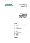
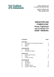
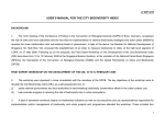
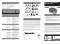
SPECIFICATIONS
AC Supply
Detection Range
Operating Temp
Timer
LUX
Protection
INSTALLATION HINTS
230/240V 50Hz
140∞ circular, 8m dia at 2.5m height.
-20oC ~ 40oC
4 sec. ~ 30 min adjustable
2 Lux ~2000 Lux adjustable.
IP44 Weather Protection when
correctly installed.
PROTECT
FROM RAIN
AIM SENSOR ACROSS,
NOT ALONG THE PATH
DON'T AIM
AT THE SUN
AIM SENSOR DOWN
TO REDUCE DISTANCE
AIM AWAY FROM
MOVING OBJECTS
KEEP AWAY FROM AIR VENTS
DON'T MOUNT ABOVE LAMPS
AVOID REFLECTED LIGHT
FROM BRIGHT SURFACES
(ie: mirror windows)
MOUNT THE
SENSOR LEVEL
140o OUTDOOR MOTION
SENSOR - IP44
Model 100SA140
Installation and Operating Instructions
Switching/Load Capacity:
Incandescent
1000W
Halogen
1000W
Fluorescent
500W
Compact Fluorescent
100W
Motor
100W
TROUBLE SHOOTING GUIDE
CAUSE
Power not on.
Wired incorrectly.
Bulbs blown.
PIR not detecting your
movement.
Light conditions too
bright.
Lights stay on.
"Time" set to high.
Wired incorrectly.
Frequent changes in
heat are being
detected.
Lights keep
turning on and
off (cycling).
Changes in heat are
being detected from a
fixed heat source.
Changes in heat are
being detected from a
moving object.
FEATURES
Product information on this and other PDL products are available on
www.pdl.co.nz and www.pdl.com.au
•
•
•
PRODUCT WARRANTY / 12 MONTHS
The 100SA140 Outdoor Motion Sensor has a 12 month warranty from
the date of purchase providing the unit is installed according to these
instructions, local wiring regulations and Codes of Practice. This
warranty is void on any unit which has been tampered with, damaged
by accident, improper operation or incorrect installation.
This guarantee is in addition to, and does not in anyway affect the
rights under the Consumer Guarantees Act 1993, if the Act applies
to the supply of this product and you are not acquiring the product
for a business use. If the Act applies and any term is inconsistent with
the terms or requirements of the Act that term shall be invalid without
affecting the remaining terms of the warranty.
Note: Under the CGA 1993, Schneider Electric advises that this
product does not contain user serviceable components thus spare
parts and repair facilities are not available.
•
•
Ideal for security lighting - reacts to intruders, visitors and family
by turning the lights ON and OFF automatically.
Motion detection for a range of 12 meters over an angle of 140o
All plastic housing - no earth wire required, ideal for replacing
existing outdoor sensors.
Adjustable light level (LUX) and time delay controls.
Can be mounted on a wall or under a soffit using the standard
mounting fixture. Can also be mounted on an internal or external
corner by using the corner mounting fixture. (Refer mounting
instructions).
PRINCIPLE OF OPERATION
The 100SA140 Passive Infrared Sensor (PIR) is a stand alone motion
sensor suitable for automatic switching of security applications in
domestic, commercial or industrial premises.
When movement of heat source (i.e. person, dog or car) within PIR
zone is detected by the sensor, it automatically switches on the light
or other connected load. If no further movement is detected the PIR
starts timing and will turn off the light after the preset “Time” period.
In the event of a warranty claim, the product must be returned to the
point of purchase or direct to Australia/New Zealand distributors
together with the proof of purchase.
As long as there is movement in the PIR field of view the lighting will
stay ON. Any movement of a heat source could cause the sensor to
switch the lighting on (including hot air movement) i.e. drafts from an
open window or door, air vents close by, cars on the street or movement
in the neighbours property. This depends on the angle of the sensor
head and the distance from the sensor.
New Zealand Head Office:
PO Box 15 355,New Lynn,
Waitakere 0640, New Zealand
Telephone +64-9-829 0490, Fax +64-9-829 0491
www.pdl.co.nz
PIR FIELD OF VIEW
PDL Electrical Products are
manufactured by
ISO 9001
REGISTERED
ED
SS
SE
AS
Sensing angle
and distance
appear incorrect
Light and heat is being
reflected back onto the
sensor.
Sudden temperature
changes due to storms
or high winds
Angle of sensor head
pointing down too far.
POSSIBLE SOLUTION
Turn on indoor switch or
check fuse.
Check wiring is the same as
diagram.
Check the bulb still functions
or replace.
Adjust the angle/direction of
the PIR.For best results walk
across the beam.
Wait until light conditions are
duller or adjust the LUX
control up.
Turn knob to lower setting (4
sec to 30 min adjustable).
Check wiring as per the
diagram
Check sensing area for
possible heat sources i.e. air
vents, moving vehicles,
moving trees, and reposition
the sensor.
Check the sensing area for
air vents, light fittings or fans
and either reposition the
sensor or adjust the aim.
Check the sensing area for
moving vehicles, pedestrians,
animals, moving trees and
alter the aim of the sensor.
Alter aim of the sensor or
paint the reflecting surface
with a dull finish.
Turn sensor off until storm
passes or install in a
sheltered location.
Raise the sensor head to
increase the sensing distance
and angle.
QU
AL
ITY
PROBLEM
Lights won't
come on.
ISO 9001
CERT NO. 11595
NATIONAL
ACCREDITATION
OF CERTIFICATION
BODIES
Schneider Electric
Industrial New Zealand,
Telarc Reg. No. 061
registered to ISO 9001.
13 July 2009
BBV1877700
Plan View
Side Elevation
Sensor
33 - 37 Port Wakefield Rd,
Gepps Cross, 5094,
South Australia
Freephone 1300 20 25 25, Freefax 1300 20 25 56
Telephone +61 8 8269 0511, Fax +61 8 8340 1724
www.pdl.com.au
100SA140 leaflet.pdf
1400
8m
approx
Sensor
8m
approx
Rev00
Not recommended
as a direction of
movement
Ideal direction
of movement
(greatest sensitivity)
Ideal
height
2–3.5
metres
12 metres (under ideal conditions)
CHOOSING A LOCATION
Horizontal and Vertical Surface mounting
1.
Once the position is chosen and wiring has been established,
position the standard base-mounting fixture over the wiring and
pass the wiring through the silicon seal.
2.
Fasten the base-mounting fixture to the surface using two 10mm
screws through either the two slots provided or two slotted knockouts provided.
The sensor can be mounted under a soffit, on a wall or using the
special mounting bracket to internal or external corners.
Before mounting select the most suitable location which will allow the
sensor to monitor intended targets without nuisance switching.
For best coverage and operating performance:
1.
DO NOT aim the sensor directly at the target area, OFFSET the
sensor to one side so you are crossing the field of view.
2.
AVOID other heat sources i.e. air vents, strong light sources,
opening windows and doors.
3.
DO NOT aim directly at large shrubs and trees which could cause
false triggering problems.
4.
DO NOT aim directly at the sun.
5.
DO NOT expose your sensor to the extremes of weather, if
possible shelter under a soffit or in a sheltered area.
6.
DO NOT expect the sensor to work at its maximum distance in
all temperature conditions. On hot nights the detecting distance
will decrease. On cold nights the distance will increase.
3.
Terminate wiring into the terminal block.
4.
Align the sensor head with the base-mounting fixture and push
it in to attach it with the base.
TIME
DELAY
10m
AMBIENT
LIGHT
CONTROL
30m
•D/D
40s
4s
"D/D" Dusk to Dawn setting, this mark is an approximate position to
set your sensor to start operating at dusk and to stop working at
dawn. This is only a starting point and could vary depending on your
requirements.
INITIAL SET UP & OPERATION
1.
NOTE: This sensor must be installed according to local
Wiring Regulations and Code of Practice.
After the power is turned on to the unit, it will take about 30
seconds to go through the warm up period and enter the TEST
MODE.
2.
In the TEST MODE the TIME and LUX adjustments will not work.
MOUNTING INSTRUCTIONS
1.
Ensure the supply is isolated at the distribution board before
beginning electrical work.
3.
When in the TEST MODE the light will turn on for about 5 seconds
each time the sensor detects movement.
Screw Pack
2.
Study the wiring diagram below BEFORE making any electrical
connections. Wiring the unit incorrectly could destroy the sensor.
4.
At this point the detection zone can be determined by adjusting
the sensors’ viewing angle to the desired area to be covered.
3.
The two Green or Green and Yellow earth wires are to be looped
together and terminated using the earth termination supplied in
the screw pack.
5.
4.
The two Blue or Black neutral wires are looped together and
terminated in the terminal marked “N”.
The TEST MODE will last about 5 minutes and will then
automatically change over to the AUTO MODE. This can also be
achieved before the 5 minutes by quickly switching the power
OFF and ON once to enter the AUTO MODE.
6.
5.
The Red or Brown wire from the supply circuit (incoming
Active/Phase) is to be terminated in the terminal that is marked
“LINE”.
Once the unit is in the AUTO MODE, all the adjusters will function
and can be adjusted to the desired settings. (REFER TO
ADJUSTMENT CONTROLS).
7.
6.
Connect the remaining Red or Brown wire (Lamp/Load) into the
terminal marked “LAMP”
When in AUTO MODE the unit can be put into MANUAL
OVERRIDE by quickly switching the power OFF and ON twice.
This will turn the light permanently on for up to six hours.
7.
The sensor head can then be lined up with the base-mounting
fixture and pushed on.
8.
In this mode any adjustments to the sensors’ controls will have
no effect.
9.
The unit will revert back to AUTO MODE after six hours, or if
required before by quickly switching the power OFF and ON once.
FOR FURTHER RECOMMENDATIONS SEE THE INSTALLATION
HINTS PAGE.
The pack contains –
2 x Plastic anchors 25mm in length for brick walls
2 x Plastite 10mm Panwasher Screws to fix the standard base
mounting to the corner-mounting fixture.
2 x Zinc plated screws 20mm in length.
2 x Blanking Inserts
Internal or External Corner mounting
1.
Once the position is chosen and wiring has been established,
remove wiring knockout hole and position corner mounting fixture.
Thread wiring through the knockout and fix the base using two
20mm screws.
2.
Align the standard mounting base to the corner mounting fixture
(terminals to the top) and pass the wiring through the silicon seal.
3.
Fasten the base mounting fixture to the corner mounting fixture
using two 10mm plastite screws.
4.
Terminate wiring into the terminal block.
5.
Align the sensor head with the base-mounting fixture and push
it in to attach it with the base.
CONNECTION TO THE POWER SUPPLY
Connection Diagram
Control
Switch
Sensor
LAMP
N
LINE
ACTIVE
After five minutes
A
(BROWN
or RED)
N
(BLUE or
BLACK)
Lamp
ADJUSTMENT CONTROLS
"
" Timer Control: This control allows adjustment of the delay time
from 4 sec. to 30 min. The timer starts working after the LAST movement
is detected. While there is movement from the heat source in the
detection area the light will remain on and the time will keep resetting.
"
" Ambient Light Control: This control allows the 100SA140 to
stay on during brighter conditions, or to operate only during low light
levels. Ideally it should be set at dusk or in the light conditions under
which the sensor and lights are expected to operate.
POWER
OFF
Switch
ON
TEST
MODE
Switch
OFF-ON
Once
(Quickly)
AUTO
MODE
Switch
OFF-ON
Twice
(Quickly)
PERMANENTLY
ON
After six hours OR
Switch OFF-ON Once (Quickly)
Warning: The 100SA140 Movement Sensor responds to the
temperature changes, care should be taken not to mount the sensor
directly above a heat source, or where hot/cold drafts will blow directly
to the sensor, or where adjacent traffic will be within the sensor’s
detection range. Typical examples are heaters or air-conditioning
units. It is important that the sensor and HVAC register be separated
by at least one meter.