1
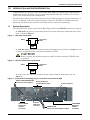
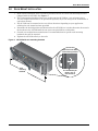
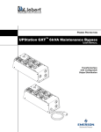
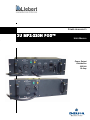
POWER AVAILABILITY
3U MP2-220N POD™
USER MANUAL
Power Output
Distribution
208 Volt
16 Amp
TABLE OF CONTENTS
IMPORTANT SAFETY INSTRUCTIONS . . . . . . . . . . . . . . . . . . . . . . . . . . . . . . . . . . . . . . . . . . . . . . . .1
GLOSSARY OF SYMBOLS . . . . . . . . . . . . . . . . . . . . . . . . . . . . . . . . . . . . . . . . . . . . . . . . . . . . . . . .2
1.0
INTRODUCTION AND SYSTEM DESCRIPTION . . . . . . . . . . . . . . . . . . . . . . . . . . . . . . . . . . . . .3
1.1
System Description. . . . . . . . . . . . . . . . . . . . . . . . . . . . . . . . . . . . . . . . . . . . . . . . . . . . . . . . . . . 3
2.0
RACK MOUNT INSTALLATION . . . . . . . . . . . . . . . . . . . . . . . . . . . . . . . . . . . . . . . . . . . . . . .4
3.0
INSTALLATION AND ELECTRICAL CONNECTIONS. . . . . . . . . . . . . . . . . . . . . . . . . . . . . . . . . .5
3.1
Power Connection Options . . . . . . . . . . . . . . . . . . . . . . . . . . . . . . . . . . . . . . . . . . . . . . . . . . . . . 5
3.2
Cord-Receptacle Installation and Start-Up . . . . . . . . . . . . . . . . . . . . . . . . . . . . . . . . . . . . . . . 5
4.0
ALTERNATE HARDWIRE INSTALLATION . . . . . . . . . . . . . . . . . . . . . . . . . . . . . . . . . . . . . . . .6
4.1
Electrical Installation Considerations . . . . . . . . . . . . . . . . . . . . . . . . . . . . . . . . . . . . . . . . . . . 6
4.2
Electrical Connections . . . . . . . . . . . . . . . . . . . . . . . . . . . . . . . . . . . . . . . . . . . . . . . . . . . . . . . . 6
4.3
Conversion From Cord-Receptacle to Hardwire . . . . . . . . . . . . . . . . . . . . . . . . . . . . . . . . . . . . 7
5.0
INDICATOR LAMPS . . . . . . . . . . . . . . . . . . . . . . . . . . . . . . . . . . . . . . . . . . . . . . . . . . . . . . .8
5.1
UTILITY Indicator Lamp. . . . . . . . . . . . . . . . . . . . . . . . . . . . . . . . . . . . . . . . . . . . . . . . . . . . . . 8
5.2
UPS Indicator Lamp. . . . . . . . . . . . . . . . . . . . . . . . . . . . . . . . . . . . . . . . . . . . . . . . . . . . . . . . . . 8
6.0
OPERATION . . . . . . . . . . . . . . . . . . . . . . . . . . . . . . . . . . . . . . . . . . . . . . . . . . . . . . . . . . . .9
6.1
Transfer to Maintenance Bypass. . . . . . . . . . . . . . . . . . . . . . . . . . . . . . . . . . . . . . . . . . . . . . . . 9
6.2
Transfer to UPS . . . . . . . . . . . . . . . . . . . . . . . . . . . . . . . . . . . . . . . . . . . . . . . . . . . . . . . . . . . . . 9
7.0
TROUBLESHOOTING . . . . . . . . . . . . . . . . . . . . . . . . . . . . . . . . . . . . . . . . . . . . . . . . . . . . . 10
8.0
SPECIFICATIONS . . . . . . . . . . . . . . . . . . . . . . . . . . . . . . . . . . . . . . . . . . . . . . . . . . . . . . . . 11
8.1
Product Warranty Registration . . . . . . . . . . . . . . . . . . . . . . . . . . . . . . . . . . . . . . . . . . . . . . . . 11
FIGURES
Figure 1
UPS mode of operation . . . . . . . . . . . . . . . . . . . . . . . . . . . . . . . . . . . . . . . . . . . . . . . . . . . . . . . . . . . . 3
Figure 2
UTILITY/maintenance bypass mode. . . . . . . . . . . . . . . . . . . . . . . . . . . . . . . . . . . . . . . . . . . . . . . . . 3
Figure 3
Front panel view showing plug-in connections to and from the UPS . . . . . . . . . . . . . . . . . . . . . . . 3
Figure 4
3U POD with rack mounting brackets. . . . . . . . . . . . . . . . . . . . . . . . . . . . . . . . . . . . . . . . . . . . . . . . 4
Figure 5
Indicator lamps on MP2-220N POD . . . . . . . . . . . . . . . . . . . . . . . . . . . . . . . . . . . . . . . . . . . . . . . . . 8
TABLES
Table 1
Installation options . . . . . . . . . . . . . . . . . . . . . . . . . . . . . . . . . . . . . . . . . . . . . . . . . . . . . . . . . . . . . . . 5
Table 2
Breaker specifications. . . . . . . . . . . . . . . . . . . . . . . . . . . . . . . . . . . . . . . . . . . . . . . . . . . . . . . . . . . . 11
i
ii
IMPORTANT SAFETY INSTRUCTIONS
SAVE THESE INSTRUCTIONS
!
WARNING
Do not attempt to service this product yourself. Opening or removing the cover may expose
you to dangerous voltages, even when the AC cord is disconnected from the electrical socket.
Refer all servicing to qualified service personnel.
This manual contains important instructions that should be followed during installation and operation of the MP2-220N POD™.
This product is designed for commercial / industrial use only, with Liebert UPS systems. It is not
intended for use with life support and other designated “critical” devices. Do not exceed POD or UPS
rating labels.
Read all safety and operating instructions before operating the MP2-220N POD and the connected
UPS system. Adhere to all warnings on the unit and in this manual. Follow all operating and user
instructions.
Turn the UPS off and unplug the MP2-220N POD before cleaning. Use only a soft cloth, never liquid
or aerosol cleaners.
The UPS and MP2-220N POD are designed for data processing equipment. Do not connect laser printers or appliances, such as hair dryers, heaters, vacuum cleaners, or electric drills, into a 3U POD powered by a UPS.
!
WARNING
Do not modify the cables in any way. The MP2-220N POD receptacles should match the UPS
input plug. The MP2-220N POD must be grounded at all times while in use. Turn off the UPS
before unplugging it.
The UPS and the MP2-220N POD are equipped with grounded plugs (plug types vary depending on
model). Do not defeat the safety purpose of this plug. If unable to fully insert the plug into the designated socket, contact a qualified electrician or your local dealer or Liebert representative for assistance.
Install in a clean temperature-controlled, indoor area free of conductive contaminants.
Route power supply cords so they are not walked on or pinched in anyway.
!
CAUTION
Risk of electric shock; do not remove center cover, no user serviceable parts inside. Wire
access covers may only be removed by qualified personnel. Refer servicing to qualified service
personnel.
!
CAUTION
!
CAUTION
!
This device receives power from multiple sources. Before servicing this device, remove all
connections and cut power from the utility branch input. Before servicing the UPS, follow
“Maintenance of UPS” instructions in the user manual for your UPS.
This device is for use in a controlled environment. Refer to 8.0 - Specifications on page 11
for environmental conditions.
WARNING
When the MP2-220N POD is in UTILITY position (maintenance bypass mode), the power to
the connected load is not filtered or conditioned by the UPS. The Liebert UPS connected
equipment guarantee is not valid while in this mode of operation.
1
GLOSSARY OF SYMBOLS
Equipment grounding conductor
Bonded to ground
Electric phase
Indicates AC input
Indicates AC output
Indicates caution followed by important instructions
2
Introduction and System Description
1.0
INTRODUCTION AND SYSTEM DESCRIPTION
Congratulations on your choice of the Liebert MP2-220N POD™ (3U POD). The 3U POD provides
maintenance bypass capability as well as power output distribution. The 3U POD can be used on
UPSs in the rack mount or tower configuration.
The 3U POD provides an isolated path of power for your UPS system for preventive maintenance or
service. As shipped, cords and receptacles provide ready to use UTILITY and LOAD connections.
Optionally, the utility input and/or the load output may be converted to hardwiring,
1.1
System Description
The 3U POD has two modes of operation: UPS (UPS available) and UTILITY (maintenance bypass).
• In UPS mode, the power is routed through the UPS system delivering conditioned power to the
load, as shown in Figure 1.
Figure 1
UPS mode of operation
POD
Utility
Connected
loads
UPS
• In UTILITY mode, the power is routed around (bypassing) the UPS system (see Figure 2). Utility power is supplied directly to the load through the 3U POD.
!
Figure 2
CAUTION
Battery back-up and conditioned power are NOT available during the UTILITY mode
of operation.
UTILITY/maintenance bypass mode
POD
Utility
Connected
loads
UPS
• In Utility mode, the UPS may be turned off and removed without affecting the load. See
Figure 3.
Figure 3
Front panel view showing plug-in connections to and from the UPS
INPUT CORD FROM UTILITY
Connect to wall receptacle
CAUTION
IF UTILITY LAMP IS ILLUMINATED
MAINTENANCE BYPASS POSITION
MAY BE SELECTED
SWITCH TO UPS POSITION ONLY
WHEN UPS LAMP IS ILLUMINATED
UTILITY
Rotary switch and
power indicator lamps
UPS
AVAILABLE
MAINTENANCE
BYPASS
AVAILABLE
UPS
Load connections
OUTPUT
12A/208V~
OUTPUT
16A/208V~
UTILITY
ON
OUTPUT
16A/208V~
LOAD
16A/208V~
CONNECT UPS
LINE CORD HERE
OFF
CONNECT TO
UPS OUTPUT
UTILITY PANEL
Remove for
hardwire
conversion
Connect
UPS input
cord here
CORD TO UPS
Connect to load receptacle of UPS
3
LOAD PANEL
Remove for
hardwire
conversion
Rack Mount Installation
2.0
RACK MOUNT INSTALLATION
1. Rack mount installation of the 3U POD is possible with the use of the rack mounting brackets
(shipped with the 3U POD). See Figure 4.
2. The rack mounting brackets allow you to rack mount the 3U POD in a 19" enclosure (23" to
19" rack adapters would have to be purchased separately if you are using our 23" Foundation or
equivalent cabinet).
3. The 3U POD can be mounted to face one of four directions depending on your application,
utilizing the rack mount brackets provided.
4. Determine the desired position and direction for the 3U POD, face it in that direction, then attach
the brackets to the 3U POD with the two (2) screws provided for each bracket.
5. Consult your rack/enclosure manufacturer’s recommendations for specific rack mounting
hardware that will be required.
6. Tighten the 3U POD securely to the rails.
Figure 4
3U POD with rack mounting brackets
Side view of 3U POD
with mounting bracket
CA
UT
ION
UT
ILIT
Y
IF UT
MAI ILITY
NT LA
MAY EN MP
BE ANCE IS ILLU
SELE BY
M
SW
CTED PASS INAT
IT
WHE CH TO
PO ED
SITI
N UP UP
ON
S LA S POSI
MP
TI
IS IL ON ON
LUM LY
INAT
ED
AV UPS
AILA
BL
E
UP
S
MAI
NT
BY ENAN
AV PASS CE
AILA
BL
E
UT
ILITY
16
CO A/208V
NN
LINE ECT ~
CO UPS
RD
HE
RE
OU
16A TPUT
/20
8V~
OU
16A TPUT
/20
8V~
CO
N
UP NECT
SO
UTP TO
UT
OU
12A TPUT
/20
8V~
ON
LOA
D
Rack
mounting
brackets
OFF
The 3U POD may be
faced in any of
four directions
4
Installation and Electrical Connections
3.0
INSTALLATION AND ELECTRICAL CONNECTIONS
Unpack the 3U POD carefully, noting the packing method. Retain the box and packing material for
possible future shipments.
Visually inspect the 3U POD for freight damage. Report damage to the carrier and your local dealer,
Liebert representative or the Liebert Worldwide Support Group.
3.1
Power Connection Options
The 3U POD may be connected to the UPS in either of two ways:
• The unit is shipped ready for connection with NEMA cords and receptacles (Cord-Receptacle
Installation).
• Alternatively, the input and output connections may be converted to hardwire applications
(Alternate Hardwire Installation).
Follow the instructions for the preferred installation option, as listed in Table 1.
Table 1
Installation options
Type of installation
Description
For installation instructions, refer to:
Cord-Receptacle
Installation
As shipped, the MP2-220N is ready to connect
using NEMA cords and receptacles.
3.2 - Cord-Receptacle Installation and Start-Up
Alternate Hardwire
Installation
The input and output connections may be
converted to hardwire applications.
4.0 - Alternate Hardwire Installation
3.2
Cord-Receptacle Installation and Start-Up
1.
2.
3.
4.
5.
6.
7.
8.
9.
10.
NOTE
This manual provides instructions for the 3U MP2-220N POD only. Refer to your UPS manual
for UPS operation and installation instructions.
Verify that the 3U POD input cord, UPS input cord and receptacle for the UPS have the same
type of configuration.
If you already have a UPS installed, turn off any connected loads and unplug them from the UPS.
Turn off the UPS and disconnect the UPS input cord.
Make sure the 3U POD rotary switch is in the UTILITY position. Plug the 3U POD input cord
(labeled “UTILITY”) into the utility outlet (wall receptacle).
WARNING: The 3U POD is now electrically live. The UTILITY lamp (amber) should be illuminated.
Plug the UPS input cord into the receptacle on top of the 3U POD labeled “CONNECT UPS LINE
CORD HERE.”
WARNING: The UPS system is now electrically live.
Connect the second 3U POD input cord (labeled “UPS”) into the matching load receptacle on the
rear of the UPS.
Plug in all loads to the load receptacles. The 3U POD now powers your equipment in the UTILITY
mode.
Turn ON the loads and ensure all are up and operating according to specification.
Start the UPS according to its specific user manual.
Verify that the UPS lamp (green) on the 3U POD is illuminated. If so, transfer the rotary switch
from UTILITY to UPS. The load is now being supplied with conditioned power through the UPS.
Before any operation or procedure, always verify that both the UPS lamp (green) and the
UTILITY lamp (amber) are illuminated before changing the status of the rotary switch.
5
Alternate Hardwire Installation
4.0
ALTERNATE HARDWIRE INSTALLATION
4.1
Electrical Installation Considerations
!
WARNING
This unit must be installed by competent electrical personnel and wired in accordance with
local/national electrical codes.
Review this entire manual and the installation instructions in this section before beginning
the installation.
Before installing, open all branch circuit power at the nearest disconnect, turn the UPS off,
and disconnect all cords to and from the UPS.
The utility input supply cable must be connected to the unit via a wall-mounted circuit breaker. The
UPS output port must also be protected with a circuit breaker connected to the load, rated to carry the
input current, and be capable of breaking the maximum prospective short circuit current of this
branch circuit. The breaker must be mounted within six feet of the UPS and be readily accessible to
the operator. Please refer to Table 2 for breaker specifications.
4.1.1
Conduit Entry and Wiring Access Doors
The side and rear of the 3U POD provide alternate conduit entry points for both UTILITY and LOAD
connections.
SIDE VIEW
REAR VIEW
4.2
Electrical Connections
The cable sizes and distribution methods used during installation are subject to local and national
electrical codes of practice and are therefore not listed in this manual. Table 2 shows the standard
current ratings.
6
Alternate Hardwire Installation
4.3
Conversion From Cord-Receptacle to Hardwire
Two wiring access panels on the front of the 3U POD allow access to the wiring compartments. Each
access door is retained using four Phillips head screws.
1. Remove the eight Phillips head screws from the wiring access panels on the front of the unit. Save
the screws.
2. Holding the panels aside, disconnect the three wires that connect each panel to the internal
terminal block. Remove the panels. DO NOT LOOSEN THE UPPER TERMINAL BLOCK
SCREWS USED FOR INTERNAL WIRING.
CAUTION
IF UTILITY LAMP IS ILLUMINATED
MAINTENANCE BYPASS POSITION
UPS
AVAILABLE
MAINTENANCE
BYPASS
AVAILABLE
UPS
UTILITY
16A/208V~
CONNECT TO
UPS OUTPUT
3. Install flexible conduit with wiring to the applicable conduit entry holes on the side or rear of the
unit.
4. Terminate the wiring to the internal terminal blocks. The wiring compartments provide terminal
blocks to connect Line, Neutral, and Ground for both the UTILITY input and the LOAD output.
5. When wiring is complete and secure, install the two blank hardwire access plates supplied with
the unit, using the eight screws removed in Step 1.
CAUTION
IF UTILITY LAMP IS ILLUMINATED
MAINTENANCE BYPASS POSITION
MAY BE SELECTED
SWITCH TO UPS POSITION ONLY
WHEN UPS LAMP IS ILLUMINATED
UPS
AVAILABLE
MAINTENANCE
BYPASS
AVAILABLE
UPS
UTILITY
16A/208V~
CONNECT UPS
LINE CORD HERE
CONNECT TO
UPS OUTPUT
Blank plate (Left)
UTILITY PANEL
Blank plate (Right)
LOAD PANEL
6. The unit is now ready to use.
Properly grounded (earthed) equipment provides multiple benefits
High quality ground (earth) connections are required for the equipment ground conductors (protective
earth) and grounding electrode conductor (power system earth connection) to reduce electrical noise
and provide for safe operation of the UPS and connected loads. Conduit used alone without a grounding conductor wire is not an acceptable connection. Size ground (protective earth) conductors equal to
circuit conductors.
For wiring information, refer to Table 2.
7
Indicator Lamps
5.0
INDICATOR LAMPS
5.1
UTILITY Indicator Lamp
This amber lamp is illuminated when utility power is present (see Figure 5). It signals that you may
transfer the loads to maintenance bypass (UTILITY mode) operation via the rotary switch. During a
utility power outage, this lamp will be off and the UPS will supply battery back-up power to the connected loads.
5.2
UPS Indicator Lamp
This green lamp is illuminated when there is output power available from the UPS (see Figure 5). It
signals that it is safe to transfer the connected loads from utility power back to UPS output power.
Figure 5
Indicator lamps on MP2-220N POD
Green lamp:
Output power available from UPS
Rotary
switch
8
Amber lamp:
UTILITY power present
Operation
6.0
OPERATION
6.1
Transfer to Maintenance Bypass
To transfer to maintenance bypass (utility) from UPS, use the following steps:
1. Ensure the UTILITY lamp (amber) is illuminated. If the lamp is not illuminated, refer to 7.0 Troubleshooting.
2. Transfer the rotary switch from UPS to UTILITY, provided the UTILITY lamp is illuminated on
the 3U POD.
3. Turn the UPS off.
4. Disconnect the two cables connecting the UPS to the 3U POD.
5. You may now service the UPS.
6.2
Transfer to UPS
To transfer to UPS from maintenance bypass (utility), use the following steps:
1. Reconnect the UPS to the 3U POD. Start the UPS according to the instructions in the UPS user
manual.
2. Verify that UPS lamp (green) on the 3U POD is illuminated. If so, transfer the rotary bypass
switch from UTILITY to UPS. If the lamp does not illuminate, refer to 7.0 - Troubleshooting.
9
Troubleshooting
7.0
TROUBLESHOOTING
Problem
Cause
Solution
Utility not present.
Call qualified service personnel to restore power.
Utility Branch Circuit Breaker may be open.
Verify that the branch circuit breaker is closed.
3U POD input power not connected to
UTILITY.
Refer to the 3U POD installation instructions in
this manual:
2.0 - Rack Mount Installation
3.0 - Installation and Electrical Connections
4.0 - Alternate Hardwire Installation
UPS output power not present.
Turn on the UPS. Refer to the UPS user manual.
UPS input and/or output cord not
connected to 3U POD.
Refer to the 3U POD installation instructions in
this manual:
2.0 - Rack Mount Installation
3.0 - Installation and Electrical Connections
4.0 - Alternate Hardwire Installation
3U POD will not
start some / all
connected loads.
Input power cannot support load.
Verify that utility and UPS are on, all circuit
protectors are closed and the load is within the
rating of the power source.
Utility or UPS circuit
protectors trip after
resetting.
Overcurrent on 3U POD connected load.
Recalculate load requirements.
UTILITY lamp
(amber) not
Illuminated.
UPS Available
lamp (green) not
illuminated.
10
Specifications
8.0
SPECIFICATIONS
Transfer Time (to and from maintenance bypass)
< 6 milliseconds
Operating Ambient Temperature
32°F to 104°F (0°C to +40°C)
Storage Ambient Temperature
-4°F to 140°F (-20°C to +60°C)
Dimensions with brackets W x D x H: in. (mm)
19.0 x 5.24 x 5.24 (482.6 x 133 x 133)
Humidity
0 to 95% non-condensing
Agency/Standards
UL1778, c-UL, ISTA Procedure 1A
Electrical Rating
See Model Label on 3U POD
This 3U POD is intended for use with a UPS meeting all the following requirements:
• UPS input cord is compatible with the rating and type of receptacle on the 3U POD labeled “CONNECT UPS LINE CORD HERE.”
• UPS output receptacle is compatible with the 3U POD input power connector labeled “UPS.”
• Available utility is compatible with the 3U POD input connection and an appropriately sized
branch circuit breaker has been provided.
Table 2
Breaker specifications
Model
VA - Volt
Rating
Input Current
Rating
at 208V
Recommended
(Maximum) External
Overcurrent Protection
Recommended Wire
(including ground wire)
(75ºC copper wire)
Maximum Wire
Accepted by
Terminal Block
Terminal
Tightening
Torque
MP2-220N
16A
20A
12 AWG
10 AWG
20 in-lb
8.1
Product Warranty Registration
To register for warranty protection:
• Visit the Quick Links section of our Web site at:
http://www.liebert.com
• Click on Product Warranty Registration and fill in the form.
If you have any questions, please contact us at:
US: 800-222-5877
Outside the US: 614-841-6755
[email protected]
11
Specifications
12
POWER AVAILABILITY
3U MP2-220N POD™
USER MANUAL
The Company Behind the Products
With over a million installations around the globe,
Liebert is the world leader in computer protection
systems. Since its founding in 1965, Liebert has
developed a complete range of support and
protection systems for sensitive electronics:
•
•
•
•
•
Environmental systems—close-control air
conditioning from 1 to 60 tons
Power conditioning and UPS with power
ranges from 300 VA to more than 1000 kVA
Integrated systems that provide both
environmental and power protection in a
single, flexible package
Monitoring and control—from systems of any
size or location, on-site or remote
Service and support through more than 100
service centers around the world and a 24/7
Customer Response Center
While every precaution has been taken to ensure
the accuracy and completeness of this literature,
Liebert Corporation assumes no responsibility and
disclaims all liability for damages resulting from
use of this information or for any errors or
omissions.
© 2003 Liebert Corporation
All rights reserved throughout the world.
Specifications subject to change without notice.
® Liebert and the Liebert logo are registered
trademarks of Liebert Corporation. All names
referred to are trademarks or registered
trademarks of their respective owners.
SL-23161 (7/03) Rev. 0
Technical Support/Service
Web Site
www.liebert.com
Monitoring
800-222-5877
[email protected]
Outside the US: 614-841-6755
Single-Phase UPS
800-222-5877
[email protected]
Outside the US: 614-841-6755
Three-Phase UPS
800-543-2378
[email protected]
Environmental Systems
800-543-2778
Outside the United States
614-888-0246
Locations
United States
1050 Dearborn Drive
P.O. Box 29186
Columbus, OH 43229
Italy
Via Leonardo Da Vinci 8
Zona Industriale Tognana
35028 Piove Di Sacco (PD)
+39 049 9719 111
Fax: +39 049 5841 257
Asia
23F, Allied Kajima Bldg.
138 Gloucester Road
Wanchai
Hong Kong
+852 2 572 2201
Fax: +852 2 831 0114