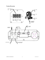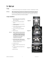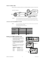
1
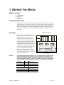
Snapshot
Q-Wash 575™
Ok on Dimmer
Outdoor OK
Sound Activated
DMX512
Master/Slave
Multitap
Transformer
Replaceable Fuse
User Serviceable
Duty Cycle
USER MANUAL
Chauvet, 3000 N 29th Ct, Hollywood, FL 33020 U.S.A.
(800) 762-1084 – (954) 929-1115
FAX (954) 929-5560
www.chauvetlighting.com
TABLE OF CONTENTS
1. BEFORE YOU BEGIN....................................................................................................................................................... 3
WHAT IS INCLUDED .............................................................................................................................................................. 3
UNPACKING INSTRUCTIONS .................................................................................................................................................. 3
AC POWER ......................................................................................................................................................................... 3
CONTACT US ...................................................................................................................................................................... 4
SAFETY INSTRUCTIONS ........................................................................................................................................................ 4
2. INTRODUCTION ............................................................................................................................................................... 5
FEATURES .......................................................................................................................................................................... 5
DMX CHANNEL SUMMARY ................................................................................................................................................... 5
PRODUCT OVERVIEW .......................................................................................................................................................... 6
3. SETUP ............................................................................................................................................................................... 7
LAMP .................................................................................................................................................................................. 7
Lamp Installation........................................................................................................................................................... 7
Fuse Replacement........................................................................................................................................................ 8
FIXTURE LINKING ................................................................................................................................................................. 8
Data Cabling ................................................................................................................................................................. 8
DMX Data Cable.................................................................................................................................................... 8
Cable Connectors .................................................................................................................................................. 9
3-Pin to 5-Pin Conversion Chart ............................................................................................................................ 9
SETTING UP A DMX SERIAL DATA LINK ................................................................................................................................ 9
MASTER/SLAVE FIXTURE LINKING ...................................................................................................................................... 10
MOUNTING ........................................................................................................................................................................ 10
Orientation ........................................................................................................................................................... 10
Rigging................................................................................................................................................................. 10
4. OPERATING INSTRUCTIONS........................................................................................................................................ 11
NAVIGATING THE CONTROL PANEL ..................................................................................................................................... 11
MENU MAP........................................................................................................................................................................ 12
CONTROL PANEL FUNCTIONS ............................................................................................................................................ 13
Program Options......................................................................................................................................................... 13
User Configurations .................................................................................................................................................... 14
To set the pan to inverting or non-inverting: ........................................................................................................ 14
To set the tilt to inverting or non-inverting: .......................................................................................................... 14
Service Functions ....................................................................................................................................................... 14
To reset the fixture:.............................................................................................................................................. 14
To turn the Lamp Power on or off: ....................................................................................................................... 14
OPERATION ....................................................................................................................................................................... 14
Stand-Alone Mode (Sound-Active, Auto Mode): ......................................................................................................... 14
Master/Slave Mode (Master Sound, Master Auto):..................................................................................................... 15
DMX Mode .................................................................................................................................................................. 15
DMX CHANNEL VALUES .................................................................................................................................................... 15
GENERAL TROUBLESHOOTING ........................................................................................................................................... 17
TECHNICAL SUPPORT ........................................................................................................................................................ 18
5. APPENDIX....................................................................................................................................................................... 18
DMX PRIMER .................................................................................................................................................................... 18
GENERAL MAINTENANCE ................................................................................................................................................... 18
RETURNS PROCEDURE ...................................................................................................................................................... 19
CLAIMS ............................................................................................................................................................................. 19
TECHNICAL SPECIFICATIONS .............................................................................................................................................. 19
Q-Wash 575 User Manual
2
2007-01-02/12:55
1. BEFORE YOU BEGIN
What is included
¾
¾
¾
¾
¾
1 x Q-Wash 575™
HMI 575W Lamp
Power Cord
Warranty Card
User Manual
Unpacking Instructions
Immediately upon receiving a fixture, carefully unpack the carton, check the contents to ensure that
all parts are present, and have been received in good condition. Notify the shipper immediately and
retain packing material for inspection if any parts appear damaged from shipping or the carton itself
shows signs of mishandling. Save the carton and all packing materials. In the event that a fixture
must be returned to the factory, it is important that the fixture be returned in the original factory box
and packing.
Figure 1 - AC Voltage Switch
AC Power
AC-100-230V
INPUT
rating is its average current draw under normal
To Ballast 230V/60Hz
specifications chart. A fixture’s listed current
To Ballast 230V/50Hz
To TRANSFORMER
particular fixture, see the label affixed to the back
plate of the fixture or refer to the fixture’s
Lamp Control to PCB in
To determine the power requirements for a
conditions. All fixtures must be powered directly
off a switched circuit and cannot be run off a
IN 240V 230V
208V 115V 100V
IN 60Hz 50Hz
rheostat (variable resistor) or dimmer circuit, even
if the rheostat or dimmer channel is used solely
for a 0% to 100% switch. Before applying power
240V
230V
208V
115V
100V
60Hz
to a fixture, check that the source voltage
matches the fixture’s requirement. Check the
50Hz
fixture or device carefully to make sure that if a
voltage selection switch exists that it is set to the
correct line voltage you will use.
Warning!
Select voltage
See the product overview for the
location of these switches.
Verify that the voltage select switch on your unit matches the line voltage applied,
and that the frequency select switch on your unit matches the frequency of the
power in your region. Also verify that you are using the correct fuse value for your
operating voltage. All fixtures must be connected to circuits with a suitable Earth
Ground. Damage to your fixture may occur if these instructions are not followed.
POWER CABLE
PIN
INTERNATIONAL
BROWN
Live
L
BLUE
Neutral
N
YELLOW/GREEN
Earth
EG (Ground)
OPERATING VOLTAGE
MUST USE CORRECT FUSE
120V
15A
230V
10A
Q-Wash 575 User Manual
3
2007-01-02/12:55
Contact Us
World Wide
General Information
Chauvet Lighting
th
3000 North 29 Court
Hollywood, FL 33020
voice: 954.929.1115
fax:
954.929.5560
toll free: 800.762.1084
Technical Support
Chauvet Lighting
th
3000 North 29 Court
Hollywood, FL 33020
voice: 954.929.1115 (Press 4)
fax:
954.929.5560 (Attention: Service)
World Wide Web
www.chauvetlighting.com
Safety Instructions
Please read these instructions carefully, which includes important
information about the installation, usage and maintenance of this
product.
•
•
•
•
•
•
•
•
•
•
•
•
•
Caution!
Please keep this User Guide for future consultation. If you sell the unit to another user, be sure that
they also receive this instruction booklet.
Always make sure that you are connecting to the proper voltage, and that the line voltage you are
connecting to is not higher than that stated on the decal or rear panel of the fixture.
This product is intended for indoor use only!
To prevent risk of fire or shock, do not expose fixture to rain or moisture. Make sure there are no
flammable materials close to the unit while operating.
The unit must be installed in a location with adequate ventilation, at least 20in (50cm) from adjacent
surfaces. Be sure that no ventilation slots are blocked.
Always disconnect from power source before servicing or replacing lamp or fuse and be sure to
replace with same lamp source.
Secure fixture to fastening device using a safety chain. Never carry the fixture solely by its head. Use
its carrying handles.
Maximum ambient temperature (Ta) is 95°F (35°C). Do not operate fixture at temperatures higher
than this.
In the event of a serious operating problem, stop using the unit immediately. Never try to repair the
unit by yourself. Repairs carried out by unskilled people can lead to damage or malfunction. Please
contact the nearest authorized technical assistance center. Always use the same type spare parts.
Don’t connect the device to a dimmer pack.
Make sure the power cord is never crimped or damaged.
Never disconnect the power cord by pulling or tugging on the cord.
Avoid direct eye exposure to the lamp while it is on.
There are no user serviceable parts inside the unit. Do not open the housing or
attempt any repairs yourself. In the unlikely event your unit may require service,
please contact CHAUVET at: 954-929-1115.
Q-Wash 575 User Manual
4
2007-01-02/12:55
2. INTRODUCTION
Features
•
•
•
•
•
•
•
•
•
•
•
•
16-channel DMX-512 moving yoke color wash
Pan: 530° / tilt: 280°
Variable strobe/shutter
CMY color mix system (cyan, magenta, yellow wheels)
Color wheel
6 colors + white
Red, blue, green, purple, 3200º & 5000ºK correction filters
Rainbow color spin in both directions at variable speeds
31 color macros
Beam shaper effect
Frost filter
Variable motorized zoom (26° - 34°)
Variable motorized dimmer (0 – 100%)
Remote fixture reset, lamp on/off and vector speed channel
Vector speed channel for CMY color mix system
Ad d i t i o n a l F e a t u r e s
•
•
•
•
•
•
Automatic pan & tilt correction
Micro-stepping motors
LED display
16bit pan/tilt resolution
Thermal switch
Fan cooled
DMX Channel Summary
CHANNEL FUNCTION
1
Pan
2
Tilt
3
Pan Fine (16-bit mode)
4
Tilt Fine (16-bit mode)
5
Vector Speed
6
Lamp and Reset
7
Color Wheel
8
Cyan
9
Magenta
10
Yellow
11
CMY Speed
12
Color Macro
13
Effect Wheel
14
Zoom
15
Strobe
16
Dimmer
Q-Wash 575 User Manual
5
2007-01-02/12:55
Product Overview
Control
Panel
Head
Yoke
Base
Access Plate
to Multitap
Transformer
DMX Input
Connector
Power Switch
Q-Wash 575 User Manual
Carrying
Handle
DMX
Output
Connector
Power Connector
& Fuse Holder
6
2007-01-02/12:55
3. SETUP
Lamp
You will need to install a lamp prior to the initial operation of the fixture. A 575W HMI lamp is included.
Warning!
When replacing the lamp, please wait 15 minutes after powering down to allow the
unit to cool down! Always disconnect from main power prior to lamp replacement.
Do not touch the envelope (glass area) of the bulb with bare hands. If this happens, clean the lamp
with alcohol and wipe it with a lint free cloth before installation.
Lamp Installation
1)
Remove the four cover screws as indicated in
figure A. Note that this is the side of the cover
with the fan showing.
2)
Figure A
Remove the two thumbscrews indicated in
figure B.
3)
Lift the fan towards the back of the head as
indicated in figure B.
4)
Pull the reflector housing towards the back of
the had as indicated in figure C.
5)
Remove the two lamp screws indicated in
figure D.
6)
Warning:
Figure B
Remove the lamp.
Nipple on lamp must be facing directly up
or directly down with respect to the head.
In other words, the nipple should NOT be
pointing towards the back of the reflector,
or towards the front of the head. Damage
to the reflector can occur if these
instructions are not followed!
7)
Hold the new lamp with a lint-free cloth and
Figure C
insert into lamp socket, making sure that the
nipple on the lamp is pointing up or down, and
not towards the reflector or front.
8)
Tighten lamp screws.
9)
Gently push reflector towards the front of the
head.
10) Lower fan towards lamp and tighten the two
Figure D
thumbscrews.
11) Replace top cover.
Q-Wash 575 User Manual
7
2007-01-02/12:55
Disconnect the power cord before replacing a fuse and always
replace with the same type fuse.
Fuse Replacement
With a flat head screwdriver wedge the fuse
holder out of its housing. Remove the damaged
fuse from its holder and replace with exact
same type fuse. Insert the fuse holder back in
its place and reconnect power.
The fuse is located
inside this
compartment.
Remove using a flat
head screwdriver.
Fixture Linking
You will need a serial data link to run light shows of one or more fixtures using a DMX-512 controller
or to run synchronized shows on two or more fixtures set to a master/slave operating mode. The
combined number of channels required by all the fixtures on a serial data link determines the number
of fixtures the data link can support.
Important:
Fixtures on a serial data link must be daisy chained in one single line. To comply with the EIA-485
standard no more than 32 devices should be connected on one data link. Connecting more than 32
fixtures on one serial data link without the use of a DMX optically-isolated splitter may result in
deterioration of the digital DMX signal.
Maximum recommended serial data link distance: 500 meters (1640 ft.)
Maximum recommended number of fixtures on a serial data link: 32 fixtures
Data Cabling
To link fixtures together you must obtain data cables. You can purchase CHAUVET-certified DMX
cables directly from a dealer/distributor or construct your own cable. If you choose to create your own
cable please use data-grade cables that can carry a high quality signal and are less prone to
electromagnetic interference.
D MX DA TA CAB LE
Use a Belden© 9841 or equivalent cable which meets the specifications for EIA RS-485 applications.
Standard microphone cables cannot transmit DMX data reliably over long distances. The cable will
have the following characteristics:
2-conductor twisted pair plus a shield
Maximum capacitance between conductors – 30 pF/ft.
Maximum capacitance between conductor and shield – 55 pF/ft.
Maximum resistance of 20 ohms / 1000 ft.
Nominal impedance 100 – 140 ohms
Q-Wash 575 User Manual
8
2007-01-02/12:55
CAB LE C ONN ECTORS
Cabling must have a male XLR connector on one end and a female XLR connector on the other end.
1
3
2
DMX connector configuration
COMMON
INPUT
1
3
2
CAUTION
1
3
2
DMX +
DMX
-
Resistance 120
ohm 1/4w between
pin 2 (DMX -) and
pin 3 (DMX +) of
the last fixture.
OUTPUT
Termination reduces signal errors and
to avoid signal transmission problems
and interference, it is always
advisable to connect a DMX signal
terminator.
Do not allow contact between the common and the fixture’s chassis ground. Grounding the common
can cause a ground loop, and your fixture may perform erratically. Test cables with an ohm meter to
verify correct polarity and to make sure the pins are not grounded or shorted to the shield or each other.
3-PIN TO 5- PIN CON VE R SION CHAR T
Note!
If you use a controller with a 5 pin DMX output connector, you will need to use a 5 pin to 3 pin adapter.
CHAUVET Model No: DMX5M, or DMX5F.
The chart below details a proper cable conversion:
3 PIN TO 5 PIN CONVERSION CHART
Conductor
3 Pin Female (output)
5 Pin Male (Input)
Ground/Shield
Pin 1
Pin 1
Data ( - ) signal
Pin 2
Pin 2
Data ( + ) signal
Pin 3
Pin 3
Do not use
Do not use
Do not use
Do not use
Universal DMX Controller
Setting up a DMX Serial Data Link
1. Connect the (male) 3 pin connector side of
the DMX cable to the output (female) 3 pin
connector of the controller.
2. Connect the end of the cable coming from
the controller which will have a (female) 3
pin connector to the input connector of the
next fixture consisting of a (male) 3 pin
connector.
This drawing provides a
general illustration of the
DMX Input/Output panel of
a lighting fixture.
3. Then, proceed to connect from the output as
stated above to the input of the following
fixture and so on.
CHAUVET Certified DMX Data Cables
Order Code
Description
DMX1.5
DMX Cable 1.5m/4.9ft
DMX4.5
DMX Cable 4.5m/14.8ft
DMX10
DMX Cable 10m/32.8ft
Continue the link
Q-Wash 575 User Manual
9
2007-01-02/12:55
Master/Slave Fixture Linking
1. Connect the (male) 3 pin connector side of the DMX cable to the output (female) 3 pin connector
of the first fixture.
2. Connect the end of the cable coming from the first fixture which will have a (female) 3 pin
connector to the input connector of the next fixture consisting of a (male) 3 pin connector. Then,
proceed to connect from the output as stated above to the input of the following fixture and so on.
Often, the setup for Master-Slave
and Standalone operation requires
that the first fixture in the chain be
initialized for this purpose via either
settings in the control panel or DIPswitches. Secondarily, the fixtures
that follow may also require a slave
setting. Please consult the
“Operating Instructions” section in
this manual for complete instructions
for this type of setup and
configuration.
Mounting
ORIENTATION
This fixture may be mounted in any position provided there is adequate room for ventilation.
R IG G IN G
Hanging Clamp
It is important never to obstruct the fan or vents pathway. Mount the
fixture using, a suitable “C” or “O” type clamp. Adjust the angle of the
fixture by loosening both knobs and tilting the fixture. After finding the
desired position, retighten both knobs.
•
When selecting installation location, take into consideration lamp replacement
access and routine maintenance.
•
•
Note!
Clamp is sold separately.
Safety cables must always be used.
Never mount in places where the fixture will be exposed to rain, high
humidity, extreme temperature changes or restricted ventilation.
•
A minimum of two mounting points must be used for this fixture.
Q-Wash 575 User Manual
10
2007-01-02/12:55
4. OPERATING INSTRUCTIONS
Navigating the Control Panel
Access control panel functions using the four panel buttons located directly underneath the LCD
Display.
Button
Function
<MODE>
Used to access the menu or to return to a
previous menu option
<ENTER>
Used to select and store the current menu
or option within a menu
<UP>
Scrolls through menu options in ascending
order
<DOWN>
Scrolls through menu options in descending
order
The Control Panel LED Display shows the menu items you select from the menu map on page 12.
When a menu function is selected, the display will show immediately the first available option for the
selected menu function. To select a menu item, press <ENTER>.
Press the <MODE> button once to activate the control panel. Pressing the <MODE> button again will
scroll through the different top-level menu options available. Use the <UP> and <DOWN> buttons to
navigate the menu options. Press the <ENTER> button to access the menu function currently
displayed or to enable a menu option. To return to the previous option or menu without changing the
value, press the <MODE> button.
Q-Wash 575 User Manual
11
2007-01-02/12:55
Menu Map
Q-Wash 575 User Manual
12
2007-01-02/12:55
Control Panel Functions
FUNCTION
OPTIONS
NOTES
NO/YES
Pan Invert (Yes or No)
NO/YES
Tilt Invert (Yes or No)
001-497
DMX Channel Address
YES
Fixture reset
dn.Co.
Pr6.1
Pr6.2
SLAE
Sou.1
Sou.2
DMX-512 Mode
Automatic Program 1 (when mounted upside down)
Automatic Program 2 (when floor positioned)
Slave Mode
Music Program 1 (when mounted upside down)
Music Program 2 (when floor positioned)
ON
OFF
Lamp on
Lamp off
X.X
Software version
Status
Too hot to strike, or no lamp
Status
Lamp error
Program Options
MENU
OPTION
DESCRIPTION
Automatic – Master Unit (Ceiling-mounted): Sets the fixture to
Master status for Master-Slave operation and the built in
programs will be triggered automatically. No data link is
required; all fixtures can be set to this mode for Stand-alone
operation.
Automatic – Master Unit (Floor-mounted): Sets the fixture to
Master status for Master-Slave operation and the built in
programs will be triggered automatically. No data link is
required; all fixtures can be set to this mode for Stand-alone
operation.
Slave Unit: Sets the fixture to run in sync with the Master.
You must set the first fixture in the data link to “Master”
otherwise nothing will happen.
Sound Active – Master Unit (Ceiling-mounted): Sets the fixture
to Master status for Master-Slave operation and the built in
programs will be triggered by the sound. No data link is
required; all fixtures can be set to this mode for Stand-alone
operation.
Sound Active – Master Unit (Floor-mounted): Sets the fixture to
Master status for Master-Slave operation and the built in
programs will be triggered by the sound. No data link is
required; all fixtures can be set to this mode for Stand-alone
operation.
DMX: The fixture will be controlled by a DMX signal coming from
a DMX controller. The starting address must be selected.
Q-Wash 575 User Manual
13
2007-01-02/12:55
User Configurations
T O SET T H E P A N T O I N V ER T I NG OR NON- IN VERT IN G:
1)
Press <MODE> until
2)
Use the <UP> and <DOWN> buttons to scroll through the two options.
inverting;
is displayed.
is non-
is inverting.
T O SET THE T I LT TO I N V ERT IN G OR NON- IN VERTING:
1)
Press <MODE> until
2)
Use the <UP> and <DOWN> buttons to scroll through the two options.
inverting;
is displayed.
is non-
is inverting.
Service Functions
T O R ES E T T H E F I XTU R E:
1)
Press the <MODE> button until
is displayed, and then press the <ENTER>
button. The fixture will now reset itself.
T O TURN TH E LAM P POW ER ON OR OF F:
1)
Press the <MODE> button until
2)
Use the <UP> and <DOWN> buttons to select the desired option and then press the <ENTER>
button.
is displayed.
turns the platform power on;
turns the platform power off.
Operation
Stand-Alone Mode (Sound-Active, Auto Mode):
This mode allows a single unit to run to the beat of the music, or the unit will auto change in Auto
Mode.
is displayed and press the <ENTER> button..
1)
Press <MODE/ESC> until
2)
Use the <UP> and <DOWN> buttons to scroll through until the desired mode is displayed and
press the <ENTER> button.
auto mode floor-mounted;
is auto mode ceiling-mounted;
is
is sound-active ceiling-mounted;
is
sound-active floor-mounted.
3)
The unit will react to the low frequencies of music via the internal microphone in Sound Active
mode, or the unit will auto change in Auto Mode.
Q-Wash 575 User Manual
14
2007-01-02/12:55
Master/Slave Mode (Master Sound, Master Auto):
This mode will allow you to link up to 32 units together without a controller.
1)
Use standard DMX cables to daisy chain your units together via the DMX connector on the rear
of the units. For longer cable runs we suggest a terminator at the last fixture. For more
information about terminators, see page 9.
2)
Choose a unit to function as the master. Press <MODE/ESC> until
is displayed
on the master unit and press the <ENTER> button..
3)
Use the <UP> and <DOWN> buttons to scroll through until the desired mode is displayed and
press the <ENTER> button.
auto mode floor-mounted;
is auto mode ceiling-mounted;
is
is sound-active ceiling-mounted;
is
sound-active floor-mounted.
4)
Press <MODE/ESC> until
is displayed on the slave units. Use the <UP> and
<DOWN> buttons to scroll through until
is displayed and press the <ENTER>
button.
DMX Mode
This mode allows the unit to be controlled by any universal DMX controller. If you are unfamiliar with
DMX, please read the DMX Primer on page 18.
is displayed.
1)
Press <MODE> until
2)
Use the <UP> and <DOWN> buttons to locate
3)
Press <MODE> until
4)
Use the <UP> and <DOWN> buttons to select the desired address and press the <ENTER>
and press the <ENTER> button.
is displayed.
button.
DMX Channel Values
CHANNEL VALUE
FUNCTION
1
000 Ù 255
Pan: 128 = halfway point
2
000 Ù 255
Tilt: 128 = halfway point
3
000 Ù 255
Pan Fine
4
000 Ù 255
Tilt Fine
5
000 Ù 255
Vector Speed (Normal > Slow)
6
000 Ù 127
128 Ù 139
140 Ù 229
230 Ù 239
240 Ù 255
Lamp & Reset
No Function
Lamp On & Reset
No Function
Lamp Off
No Function
7
000 Ù 017
Color Wheel
White (Open)
Q-Wash 575 User Manual
15
2007-01-02/12:55
018 Ù 035
036 Ù 051
052 Ù 071
072 Ù 089
090 Ù 107
108 Ù 127
128 Ù 187
188 Ù 195
196 Ù 255
Red
Blue
Green
Purple
Color Correction: 6000K
Color Correction: 3200K
Rainbow Effect (Slow > fast)
No Function
Reverse Rainbow Effect (Slow > Fast)
8
000 Ù 255
Cyan (0 – 100%)
9
000 Ù 255
Magenta (0 – 100%)
10
000 Ù 255
Yellow (0 – 100%)
11
000 Ù 255
CMY Speed (Fast > Slow)
12
000 Ù 015
016 Ù 023
024 Ù 031
032 Ù 039
040 Ù 047
048 Ù 055
056 Ù 063
064 Ù 071
072 Ù 079
080 Ù 087
088 Ù 095
096 Ù 103
104 Ù 111
112 Ù 119
120 Ù 127
128 Ù 135
136 Ù 143
144 Ù 151
152 Ù 159
160 Ù 167
168 Ù 175
176 Ù 183
184 Ù 191
192 Ù 199
200 Ù 207
208 Ù 215
216 Ù 223
224 Ù 231
232 Ù 239
240 Ù 247
248 Ù 255
Color Macro
No Function
Macro 1
Macro 2
Macro 3
Macro 4
Macro 5
Macro 6
Macro 7
Macro 8
Macro 9
Macro 10
Macro 11
Macro 12
Macro 13
Macro 14
Macro 15
Macro 16
Macro 17
Macro 18
Macro 19
Macro 20
Macro 21
Macro 22
Macro 23
Macro 24
Macro 25
Macro 26
Macro 27
Macro 28
Macro 29
Macro 30
13
000 Ù 070
071 Ù 180
181 Ù 255
Effect Wheel
No Function
Beam Shaper
Frost
14
000 Ù 255
Zoom: Out > In
15
000 Ù 031
032 Ù 063
064 Ù 095
096 Ù 127
128 Ù 130
131 Ù 159
160 Ù 191
192 Ù 223
224 Ù 255
Strobe
No Function
Open
Strobe (Slow > Fast)
Open
No Function
Pulse Strobe (Slow > Fast)
Open
Random Strobe (Slow > Fast)
Open
16
000 Ù 255
Dimmer
Closed > Open (0 – 100%)
Q-Wash 575 User Manual
16
2007-01-02/12:55
General Troubleshooting
Applies to
Symptom
Solution(s)
Lights
Foggers
& Snow
Controllers
Dimmers
& Chaser
Auto shut off
Check fan thermal switch reset
9
Beam is very dim or
not bright
Clean optical system or replace lamp
Check 220/110v switch for proper setting
9
Breaker/Fuse keeps
blowing
Check total load placed on device
Chase is too slow
Check users manual for speed adjustment
9
9
9
Device has no power
Check for power on Mains.
Check device’s fuse. (internal and/or external)
9
9
9
Fixture is not
responding
Check DMX Dip switch settings for correct addressing
Check DMX cables
Check polarity switch settings
9
Fixture is on but
there is no
movement to the
audio
Make sure you have the correct audio mode on the
control switches. If audio provided via ¼” jack, make
sure a live audio signal exists
Adjust sound sensitivity knob
9
9
9
Lamps cuts off
sporadically
Possible bad lamp or fixture is overheating.
Lamp may be at end of its life.
9
Light will not come
on after power failure
Some discharge lamps require a cooling off period
before the electronics in the fixture can kick start it
again, wait 5 to 10 minutes before powering up
9
Loss of signal
Use only DMX cables
Install terminator
Note: Keep DMX cables separated from power cables
or black lights.
9
9
9
Moves slow
Check 220/110v switch for proper setting
9
No flash
Re-install bulb, may have shifted in shipping
9
No laser output
Bounce mirror motor may have shifted during shipping,
readjust
9
No light output
Check slip ring & brushes for contact
Install bulb
Call service technician
9
Relay will not work
Check reset switch
Check cable connections
Remote does not
work
Make sure connector is firmly connected to device
9
Stand alone mode
All Chauvet lighting fixtures featuring stand-alone
functions do not require additional settings, simply
power the fixture and it will automatically enter into this
mode
9
9
9
9
9
If you still have a problem after trying the above solutions, please contact CHAUVET Technical
Support at the location on the next page.
Q-Wash 575 User Manual
17
2007-01-02/12:55
Technical Support
Address: Service Dept.
3000 N 29th Ct, Hollywood, FL 33020 (U.S.A.)
Support (Email): [email protected]
Telephone: (954) 929-1115 - (Press 4)
Fax: (954) 929-5560 - (Attention: Service)
Website: http://www.chauvetlighting.com
5. APPENDIX
DMX Primer
There are 512 channels in a DMX-512 connection. Channels may be assigned in any manner. A
fixture capable of receiving DMX 512 will require one or a number of sequential channels. The user
must assign a starting address on the fixture that indicates the first channel reserved in the controller.
There are many different types of DMX controllable fixtures and they all may vary in the total number
of channels required. Choosing a start address should be planned in advance. Channels should
never overlap. If they do, this will result in erratic operation of the fixtures whose starting address is
set incorrectly. You can however, control multiple fixtures of the same type using the same starting
address as long as the intended result is that of unison movement or operation. In other words, the
fixtures will be slaved together and all respond exactly the same.
DMX fixtures are designed to receive data through a serial Daisy Chain. A Daisy Chain connection is
where the DATA OUT of one fixture connects to the DATA IN of the next fixture. The order in which
the fixtures are connected is not important and has no effect on how a controller communicates to
each fixture. Use an order that provides for the easiest and most direct cabling. Connect fixtures
using shielded two conductor twisted pair cable with three pin XLR male to female connectors. The
shield connection is pin 1, while pin 2 is Data Negative (S-) and pin 3 is Data positive (S+). CHAUVET
carries 3-pin XLR DMX compliant cables, DMX-10 (33’), DMX-4.5 (15’) and DMX-1.5 (5’)
General Maintenance
To maintain optimum performance and minimize wear fixtures should be cleaned frequently. Usage
and environment are contributing factors in determining frequency. As a general rule, fixtures should
be cleaned at least twice a month. Dust build up reduces light output performance and can cause
overheating. This can lead to reduced lamp life and increased mechanical wear. Be sure to power off
fixture before conducting maintenance.
Unplug fixture from power. Use a vacuum or air compressor and a soft brush to remove dust
collected on external vents and internal components. Clean all glass when the fixture is cold with a
mild solution of glass cleaner or Isopropyl Alcohol and a soft lint free cotton cloth or lens tissue. Apply
solution to the cloth or tissue and drag dirt and grime to the outside of the lens. Gently polish optical
surfaces until they are free of haze and lint.
The cleaning of internal and external optical lenses and/or mirrors must be carried out periodically to
optimize light output. Cleaning frequency depends on the environment in which the fixture operates:
damp, smoky or particularly dirty surrounding can cause greater accumulation of dirt on the unit’s
optics. Clean with soft cloth using normal glass cleaning fluid. - Always dry the parts carefully. - Clean
the external optics at least every 20 days. Clean the internal optics at least every 30/60 days.
Q-Wash 575 User Manual
18
2007-01-02/12:55
Returns Procedure
Returned merchandise must be sent prepaid and in the original packing, call tags will not be issued.
Package must be clearly labeled with a Return Merchandise Authorization Number (RA #). Products
returned without an RA # will be refused. Call CHAUVET and request RA # prior to shipping the
fixture. Be prepared to provide the model number, serial number and a brief description of the cause
for the return. Be sure to properly pack fixture, any shipping damage resulting from inadequate
packaging is the customer’s responsibility. CHAUVET reserves the right to use its own discretion to
repair or replace product(s). As a suggestion, proper UPS packing or double-boxing is always a safe
method to use.
Note:
If you are given an RA #, please include the following information on a piece of paper
inside the box:
1)
Your name
2)
Your address
3)
Your phone number
4)
The RA #
5)
A brief description of the symptoms
Claims
Damage incurred in shipping is the responsibility of the shipper; therefore the damage must be
reported to the carrier upon receipt of merchandise. It is the customer's responsibility to notify and
submit claims with the shipper in the event that a fixture is damaged due to shipping. Any other claim
for items such as missing component/part, damage not related to shipping, and concealed damage,
must be made within seven (7) days of receiving merchandise.
Technical Specifications
WEIGHT & DIMENSIONS
Length.............................................................................................................................. 16 in (406 mm)
Width ............................................................................................................................... 16 in (406 mm)
Height .............................................................................................................................. 23 in (584 mm)
Weight ............................................................................................................................. 75.8 lbs (34 kg)
POWER
Operating Voltage (internally selectable) ....................................... 100V, 115V, 208V, 230V - 50/60 Hz
AC input plug ................................................................................................................... IEC 60320 C14
Fuse....................................................................................................20mm Glass 15A 250V Fast Blow
Power consumption ........................................................................................................................ 720W
Inrush............................................................................................................................................ 1224W
PHOTO OPTIC
Beam angle ................................................................................................................................ 26° - 34°
Pan ................................................................................................................................................... 530°
Tilt..................................................................................................................................................... 280°
Illuminance at 1m ....................................................................................................3,430 fc (36,906 lux)
LAMPS
Bulb ...............................................................................................................................HMI 575W Lamp
CONTROL & PROGRAMMING
Data input ................................................................................................ locking 3-pin XLR male socket
Data output ........................................................................................... locking 3-pin XLR female socket
Data pin configuration ..............................................................................pin 1 shield, pin 2 (-), pin 3 (+)
Protocols........................................................................................................................ DMX-512 USITT
DMX Channels .....................................................................................................................................16
ORDERING INFORMATION
Q-Wash 575™..................................................................................................................... Q-WASH575
WARRANTY INFORMATION
Warranty .............................................................................................................. 2-year limited warranty
Q-Wash 575 User Manual
19
2007-01-02/12:55