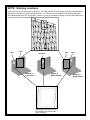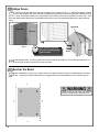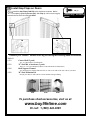
1
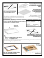
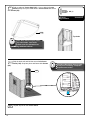
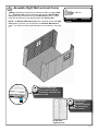
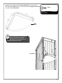
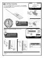
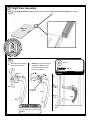
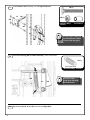
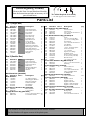
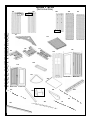
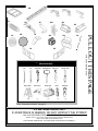
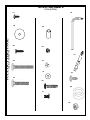
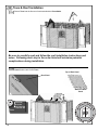
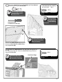
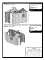
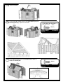
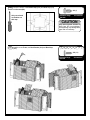
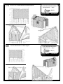
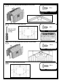
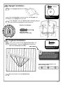
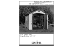
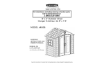
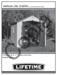
OWNER’S MANUAL with Assembly Instructions
8'x10' Outdoor Shed
Sentinel
8’ x 10’ Outdoor Shed
MODEL #6404
You could win $200!
Register your product at www.lifetime.com and receive three important benefits:
1. You automatically will be entered to win $200 in our monthly drawing!
2. In the unlikely event of a product recall or safety modification, we can notify you immediately and directly.
3. You may choose to receive Preferred Customer Announcements and promotions regarding new Lifetime
products.
www.lifetime.com
Level Surface Notice:
Surface must be leveled before installation. We recommend building a level work space with a cement or patio style
surface. If the surface is not properly leveled, the Outdoor Shed will not assemble correctly. Proper surface leveling will
save you time in the long run, so please do not ignore this step.
Building Code Notice:
Consult all local building codes, as well as city and county ordinances, to ensure that the construction of the Outdoor
Shed does not require a building permit. Proper building permit documentation may be required in your neighborhood,
and it would be unfortunate to learn this after constructing the Shed.
Screwdriver Notice:
There is a 1/2” phillips head screwdriver bit included with the shed hardware. This bit can be used with any power
screwdriver or drill. The plastic pieces of your shed can be damaged by overtightening of screws. To avoid damage we
strongly recommend the use of a low-powered power screwdriver or a drill that has an adjustable clutch that is set on a
low torque setting. If neither is available, use a hand screwdriver. In any case, use caution to avoid overtightening the
screws.
Floor Puncture Notice:
Sharp objects may damage your floor. If resting sharp, heavy objects on your shed floor, place a block of wood between
the sharp object and floor.
Congratulations on your Lifetime® Outdoor Shed purchase. By following the instructions below, your new Lifetime shed
should provide you with years of service and enjoyment.
Cleaning and Care
The polyethylene walls and shelves are stain- and solvent resistant. To clean, use a mild soap and a soft-bristled brush. Abrasive
cleaning materials may scratch the plastic and are not recommended. Repair scratches or rust spots on the metal by sanding
the affected area lightly; using a rust preventative spray primer; and finally, spraying with a high-gloss spray enamel paint. Avoid
placing a direct heat source on or near surfaces unless using a heat barrier.
SAFETY INSTRUCTIONS
FAILURE TO FOLLOW THESE WARNINGS MAY RESULT IN SERIOUS INJURY OR PROPERTY DAMAGE AND WILL VOID
WARRANTY.
To ensure safety, do not attempt to assemble this shed without following the instructions carefully. Check entire box and
inside all packing material for parts and/or additional instruction material. Before beginning assembly, read the instructions
and identify parts using the hardware identifier and parts list in this document. Proper and complete assembly, use and
supervision are essential for proper orientation and to reduce the risk of accident or injury.
• Do not use or store hot objects such as grills, blowtorches, welding equipment, etc. in the shed.
• If using a ladder during assembly, use extreme caution.
• Two capable adults are required for shed assembly. (It is also recommended that a third adult function as an
instruction reader.)
Most injuries are caused by misuse and/or not following instructions. Use
caution when using this shed.
2
INSTRUCTION #1018238
8/28/2006
Read This First!
Before Beginning Assembly:
A. Read the “Congratulations” letter on pages 4-5.
B. Remove Parts List from the center of these instructions and
make sure all parts are present and in good condition.
C. Find the color “Construction Tips” flyer and refer to it
during assembly.
**Do Not Contact the Store!**
For Assistance, including missing or broken parts,
Call Customer Service at:
1 (800) 225-3865
** Customers outside of the U.S. or Canada, please contact the store for assistance. **
KEY
Indicates that a hand
screwdriver is required
for a step.
Indicates a helpful hint or
important note.
Refers you to a specific step
in the full-color Construction
Tips flyer.
Suggested Tools & Materials
(Not Included):
Two Adults Required for Assembly
( + one Adult suggested as an instruction reader)
7/16”
3/8”
(2)
(1)
Step Ladder
(2)
Adjustable
(1)
Rubber Mallet
Box Knife
Phillips Head
(1)
(1)
(1)
Power Drill *
Work Light
(1)
(1)
Pliers
(1)
Flashlight
(1)
* see “Screwdriver Notice” on page 2
3
IMPORTANT! Please Read
Dear Valued Customer,
®
or Storage Shed! We
your purchase of a Lifetime Outdo
on
you
te
tula
gra
con
to
like
uld
with your new
We wo
ice and you will be very pleased
cho
fect
per
the
de
ma
e
hav
you
t
are confident tha
storage solution.
nufactured by
family of brands created and ma
the
of
t
par
is
d
She
e
rag
Sto
or
your
This Outdo
can be assured that the quality of
you
ts,
duc
pro
our
of
®
all
e
Lik
.
Inc
Lifetime Products,
ds are made in the USA,
the best in the world! All of our she
is
d
She
e
rag
Sto
or
tdo
Ou
e
tim
Life
ering the best
d, we back that quality up by off
An
us.
to
nt
orta
imp
y
ver
is
t
tha
d… top to
something
that covers everything on the she
ty
rran
wa
r
yea
10A
–
ss
ine
bus
warranty in the
bo om!
The design and
ality steel and polyethylene parts.
t-qu
hes
hig
the
h
wit
lt
bui
are
ds
All of our she
none. All of our exposed
d double-wall panels is second to
construction of our steel-reinforce
t polyethylene plastic.
coated and we only use high-impac
der
pow
are
s
sse
tru
and
ts
par
l
stee
and, it won’t crack
superior strength and durability,
has
It
?
cial
spe
so
ene
hyl
yet
pol
What makes
or degrade outdoors.
®
rage Shed, please
ge ing in a Lifetime Outdoor Sto
are
you
lity
qua
the
w
kno
you
t
So now tha
TRUCTION MANUAL!
take the time to READ THIS INS
s to help you put
the best possible form of instruction
ing
vid
pro
in
e
car
at
gre
en
tak
e
the following
We hav
ore you get started, PLEASE read
Bef
er.
eth
tog
d
She
e
rag
Sto
or
tdo
your new Ou
ted!
preparation tips to help you get star
le if you do!
erience will be a lot more enjoyab
exp
n
ctio
stru
con
r
you
,
you
ure
We can ass
PREPARATION TIPS:
built
a great purchase, but Rome was not
de
ma
e
hav
You
!
AX
REL
…
ple
• The first step is sim
r fine Outdoor Storage
your a ernoon pu ing together you
of
t
par
d
goo
a
nd
spe
to
n
Pla
.
e apart quickly
in a day
quickly and easily, it surely will com
er
eth
tog
es
com
it
if
is,
phy
loso
patient, and
Shed. Our phi
will surely last for years if you are
d
®
She
e
rag
Sto
or
tdo
Ou
e
tim
and easily! Your Life
.
it together as we have instructed
take all the time necessary to put
nd that not
one-person endeavor. We have fou
a
not
is
s
Thi
!
fun
the
on
in
join
• Grab a friend to
ing in the construction of
have two or more people participat
you
if
her
oot
sm
go
gs
thin
l
wil
y
onl
well. So, the more the merrier!
the shed, but it will go quicker as
e included
structing your new shed. We hav
con
for
ary
ess
nec
ls
too
the
all
e
• Make sure you hav
screwdriver or drill.
that may be used with any power
bit
r
rive
wd
scre
d
hea
s
llip
Phi
“
ome damaged
a 1/2
plastic pieces of your shed may bec
The
it.
use
ase
ple
nd…
frie
r
of a lowThis bit is you
, we strongly recommend the use
age
dam
this
id
avo
To
ws.
scre
by overtightening the
that is set on a low-torque
drill that has an adjustable clutch
a
or
r
rive
wd
scre
er
pow
d
ere
pow
- 1 -
4
r. If a hand screwdriver is all you
a hand screwdrive
se ing. If neither is available, use
need it!
several breaks… your wrist will
en it comes time to do the roof!),
ladders (wh
• You will also need two small step
and a 3/8” wrench.
have, take
a 7/16” wrench
ROW THE WOOD
is there for a reason. DO NOT TH
box
d
she
r
you
in
ck
blo
od
wo
• The small
oor.
a aching the wall panels to the fl
BLOCK AWAY, it is necessary for
rt before you start.
nual and “Construction Tips” inse
ma
tion
ruc
inst
ire
ent
the
h
oug
yourself with
• Read thr
of the process and to familiarize
ow
fl
the
for
feel
a
get
to
e
ctic
pra
It’s always a great
process out of order.
get ahead of yourself and start the
the parts involved. But, try not to
certain order,
R! Everything goes together in a
DE
OR
IN
NS
TIO
UC
TR
INS
E
• FOLLOW TH
f-the-art research and
rect order should be. In our state-o
and we have learned what that cor
order of construction is
y created these instructions. The
ngl
aki
nst
pai
e
hav
we
,
lity
faci
ow along with
testing
l not fit if built out of order. Just foll
wil
ply
sim
ts
par
e
som
and
,
son
y smooth.
there for a rea
fit together and things will go ver
l
wil
ing
ryth
eve
and
s
tion
ruc
the order in the inst
spots. We have
insert for the trickier construction
s”
Tip
tion
ruc
nst
“Co
r
colo
the
y we included
• Refer to
ere it can get a bit tricky, that is wh
wh
n
ctio
stru
con
ing
dur
ces
pla
identified a few
guide you through the
ruction extra was created to be er
the color insert. This full-color inst
d builder.
much happier Outdoor Storage She
process. Use it and you will be a
sen to place
SURFACE! If the spot you have cho
EL
LEV
A
ON
ILT
BU
BE
ST
• YOUR SHED MU
l not assemble correctly!
rage Shed is not level, the shed wil
Sto
or
tdo
Ou
new
l
rfu
nde
wo
r
you
last a long time, so
le surface. Your shed is meant to
sty
io
pat
or
ent
cem
el
lev
a
nd
We recomme
it before you start to build.
provide the proper foundation for
lding codes, as well
allowed to build it! Consult all bui
are
you
e
sur
ke
ma
it,
ld
bui
you
to construct
• Before
do not require a building permit
you
t
tha
ure
ens
to
s,
nce
ina
ord
as city and county
y be required in your
building permit documentation ma
your Outdoor Storage Shed. Proper
r Outdoor Storage Shed is
unfortunate to learn this a er you
te
qui
be
uld
wo
it
and
,
ood
orh
neighb
already built!
Outdoor Storage
construction of your wonderful new
the
in
beg
to
dy
rea
’re
you
t
tha
w
No
enjoy yourself. We
yourself a large cold beverage and
get
,
ath
bre
p
dee
a
e
tak
k,
bac
will be able to
Shed, step
of time in building your shed, you
t
oun
am
t
righ
the
ng
ndi
spe
er
guarantee that a
enjoy it for years to come.
®
tdoor Storage, and have fun!
Thanks for choosing Lifetime Ou
- 2 -
5
1
Site Selection
1a
The actual dimensions of your shed (at its widest and longest points) are 8’ x 10’. Be sure
to select a site that will accommodate these measurements. The base of the shed is
slightly smaller than this, so you will need to create a level surface that is at least 93.5” x
118.25”. We recommend using a level cement or patio style surface. This will provide the
best long-term performance for your shed.
8’
93.5”
10’
10’
118.25”
NOTICE: Shed Extension Kits are available for this shed.
Please consider possible shed expansion when planning the
site for your shed. See inside the back cover of this manual for
information on ordering Extension Kits.
Surface must be leveled before installation. If
the surface is not properly leveled, the outdoor
shed will not assemble or function correctly.
Proper surface leveling will save you time in the long
run, so please do not ignore this step.
8’
Alternate Site Preparation
Wherever possible you should use the surfaces described above. When this is not possible, we
recommend you use one of the following options:
Note: Any platform or similar structure should be built above ground in order to avoid water pooling inside shed.
OPTION 1: Wood Platform
Be sure you use lumber that is treated and approved for
outdoor use. Build outside frame to 93 1/2” x 118 1/4” outside
dimensions:
”
118 1/4
Item
Qty.
2” x 4” x 90 1/2” treated board*
8
2” x 4” x 118 1/4” treated board*
2
48” x 93 1/2”’ Plywood (ACX)**
2
22 1/4” x 93 1/2” Plywood (ACX)**
1
16d 3” common nails
32
8d 1 1/2” common nails
36
* All lumber must be rated for outdoor use.
** Trim 4’ x 8’ sheets to this size.
93
16”
1/
2”
16”
16”
16”
16”
25”
15.
To be sure to have studs
in the correct location to
nail plywood in the next
step, start measuring here
& measure from center to
center.
6
Place the 2” x 4” x 90 1/2” boards
on the inside of the frame. Nail each
board in place with the 16d nails.
Line up a large sheet of outdoor
rated plywood (48” x 93.5”) with
the end of the frame (same end
you measured from). Nail plywood
in place.
B
A
Place next large sheet.
Cut last sheet of plywood
to fit remaining space
(22”x93.5”) on frame. Nail
plywood in place.
Square up the frame by measuring
from corner to corner. Measurement
A should equal Measurement B.
Drill 3 evenly spaced 1/2” drain
holes in plywood between each 2” x
4” joist.
Place platform in the desired location. If platform does not
rest level on the ground, build up low points with loose dirt
until platform is stable.
OPTION 2: Filled Wood Frame
Item
Qty.
2
2
8d 1 1/2” common nails
16
1” ‘L’ bracket
4
“Pea” gravel
9.8 cu. ft. (aprox.)
Leveling board (2” x 4” x 10’)
1
Be sure you use lumber that is treated and approved for outdoor use. 2” x 4” x 7’ 5” treated board*
2” x 4” x 10’ treated board*
Cut outside frame to 8’ x 10’ outside dimensions:
Be sure that
frame is level.
10’
* Must be rated for outdoor use
A
B
8’
Square up the frame by measuring from
corner to corner. Measurement A should
equal Measurement B.
Nail an L-bracket on each corner of
the frame with 8d nails.
Place platform in the desired location. If platform does not rest level on the ground, build up low points with
loose dirt or “Pea” gravel, until platform is stable.
Use aprox. 9.8
cu. ft. of “pea”
gravel.
Once all boards are level and do not wobble,
pack “Pea” gravel or dirt around the outside of
the frame, and slope away from frame.
Now fill the inside of the frame with “Pea” gravel. Use
a leveling board to scrape off extra fill material and to
level the surface.
7
Before Beginning!
Remove the Parts List from the center of this manual, and locate
color “Construction Tips” insert in box.
2
Assemble Floor
2a
Lay Outer Floor Panel (109) flat on the ground.
Hold a Center Floor Panel (110) at an angle
(as shown) and fit tabs into slots and lay Center Floor
Panel flat. Add next Center Panel (110) and last Outer
Panel (109).
1.
CAUTION
Sharp objects may damage your
floor. If resting sharp, heavy
objects on your shed floor, place a
block of wood between the sharp
object and floor.
2.
110
3.
109
110
109
3
Assemble Window
3a
Remove plastic sheeting from Window (AA) and slide
Window into slot on the Window Wall Panel (125).
Attach a Window Latch (HQ) above each corner of the Window
as shown. When tightening Screws (SS), ensure the Window
Latches slide freely.
3b Do not overtighten. Insert Screw (TC) into the hole in the
window. Set panel aside. Repeat steps 3a and 3b for the
second Window.
SS (8)
TC (2)
HQ (4)
Hardware Bags:
1001632
1015974
1004015
Screwdriver
HQ
HQ
Insert window
with bent edge at
top and pointing
away from the wall.
8
Place screw (TC) in this hole to
keep window from sliding up
too far. Insert until flush with the
window
4
Assemble Front Corner
4a
Fold Left Corner Panel (105). Fit tabs of panel into the front left corner (while
facing shed) of your floor. Place a Wood Block (BC) under Floor Panel, directly
under first tab, then pull down on Corner Panel until tab snaps into place. Move block
under the next tab and repeat.
105
Place Wood Block (BC) directly
under the tab you are inserting. Snap
tabs into place one at a time.
4b
Fold up edges of Corner Shelf (121). Line-up holes in Corner
Shelf with top set of pre-made holes in Left Corner Panel and
secure with Screws (SS).
SS (4)
Hardware
Bags:1001632
Screwdriver
121
Top holes
Corner Shelf should only be placed
in top set of holes. See inside the
back cover for information on
purchasing additional shelves.
9
5
Assemble Left Wall and Back Corners
5a
NOTE: The Window Wall Panel (125) may be inserted into any side Wall
Panel position; however, you should place one Window Wall Panel offcenter. You will then have enough wall space for your shelving. See page
11.
Place Wood
Block (BC)
directly under
the tab you are
inserting. Snap tabs
into place one at a
time.
1.
5b
SS (20)
Snap Wall Panels (108) into place along the side of shed. Ensure
holes line up and then secure panels together with Screws (SS).
Hardware Bags:
1001632
Screwdriver
Second person
should apply
pressure on opposite
side of the wall for easy
insertion of screws.
Do Not Over-Tighten Screws
2.
3.
Fold Right Corner Panel (104). Snap into place and secure with
Screws (SS).
104
Place Wood Block (BC) directly under
the tab you are inserting. Snap tabs
into place one at a time.
10
NOTE: Shelving Locations
Keep in mind where you would like your shelving. You install shelving on Shelf Support Channels. The
Channels may be installed on the Window Wall Panel when Window Wall Panel is in any position. However,
you can only install the shelving on regular Wall Panels when those two Wall Panels are adjacent.
Here
Here
Here
Only Here
Window in
Left Position
Window in
Middle Position
Here
Window in
Right Position
Shelf Support Channels can also
be installed in the Window Wall
Panel, as shown.
11
5c
Fold up edges of Corner Shelf (121). Line-up holes in Corner
Shelf with top set of pre-made holes in Corner Panel and secure
with Screws (SS).
SS (4)
Hardware
Bags:1001632
Screwdriver
121
Top holes
Corner Shelf should only be placed
in top set of holes. See inside
the back cover for information on
purchasing additional shelves.
5d
Skip the back wall and fold the second Left Corner
Panel (105). Snap into place and fasten with Screws
(SS).
105
5e
12
Repeat step 5c for this Corner Panel.
Place Wood Block (BC) directly under
the tab you are inserting. Snap tabs
into place one at a time.
6
Assemble Right Wall and Last Corner
6a
Assemble the right wall as you did the left wall by snapping Wall
Panels (108) into place along the side of shed. Window Wall
Panel (125) may be inserted into any side Wall Panel position. Ensure
holes line up and then secure panels together with Screws (SS).
NOTE: The Window Wall Panel (125) may be inserted into any side Wall
Panel position; however, you should place one Window Wall Panel offcenter. You will then have enough wall space for your shelving. See page
14.
SS (20)
Hardware Bags:
1001632
Screwdriver
Place Wood Block (BC)
directly under the tab you
are inserting. Snap tabs into
place one at a time.
Second person
should apply
pressure on opposite
side of the wall for easy
insertion of Screws.
Do Not OverTighten Screws
13
NOTE: Shelving Locations
Keep in mind where you would like your shelving. You install shelving on Shelf Support Channels. The Channels
may be installed on the Window Wall Panel when Window Wall Panel is in any position. However, you can only install
the shelving on regular Wall Panels when those two Wall Panels are adjacent.
Here
Here
Here
Only Here
Window in
Left Position
Window in
Middle Position
Shelf Support Channels can also
be installed in the Window Wall
Panel, as shown.
14
Here
Window in
Right Position
6b
Fold up edges of the last Corner Shelf (121). Line-up holes in
Corner Shelf with top set of pre-made holes in Right Corner Panel
and secure with Screws (SS).
SS (4)
Hardware
Bags:1001632
Screwdriver
121
Corner Shelf should only be placed
in top set of holes. See inside
the back cover for information on
purchasing additional shelves.
Top holes
15
7
Left Door Assembly
HM (4)
7a
Rest Left Door (118) with front side down. Position Deadbolt
Latches (HM) in slots at top and bottom of door, and slide Door
End Channel (AG) onto the door.
(Not Actual Size)
Hardware Bags:
1015974
TOP
Rubber Mallet (1)
HM
Back of
Door
Door End Channel fits
onto door with the flat
side up (facing the Dead
bolt Latches).
HM
BOTTOM
7b
Install Left Door Handle (BB). Set door aside.
HC (4)
You may need to nudge the
Door End Channel to make
the holes line up with the
gap in the door.
PB (6)
HL (4)
Hardware Bags:
1015974
1.
BB
VC
HP
HL
PB
Back of
Door
16
7/16” Wrenches (2)
Screwdriver
2.
HC
7c
VC (6)
Repeat steps 7a and 7b for the second Left Door.
CAUTION
Do not overtighten. Overtightening
may damage parts and void
warranty.
8
Right Door Assembly
8a
Rest Right Shed Door (119) with front side down, and slide Door End Channel (AG) onto the door.
Back of
Door
8b
1.
Fit Thumb Lever Knobs
into Handle Grooves.
2.
VC (6)
Rotate the Thumb Lever into
the handle. Slide forward
until the Knobs fit into the
holes in the handle.
PB (6)
Hardware Bags:
1015974
Groove
Screwdriver
3.
HG
Knob
PB
HG
HG
Knobs snap
into Holes
VC
BA
PB VC
BA
BA
CAUTION
Do not overtighten. Overtightening
Attach the Handle and Thumb lever to the
Door.
may damage parts and void
warranty.
17
8c
Install Handle Latch assembly onto the Right Shed Door.
HB (4)
HH (4)
HI
HA
HR (4)
HR
Hardware Bags:
1015974
Screwdriver
HH
7/16” Wrenches (2)
HB
You may need to nudge the
Door End Channel to make
the holes line up with the gap in
the door.
HN
8d
Attach Door Spring (HD) to Handle assembly. Set the door aside.
HD (2)
(Not Actual Size)
Hardware Bags: 1015974
HD
HI
8e
18
HA
Repeat steps 8a, 8b, 8c and 8d for the second Right Door.
Use pliers to pull
spring down and hook
into bottom hole.
Before Beginning Assembly
Remove this Parts List and Hardware Identifier
from the Instructions and take an inventory of all
parts in both boxes.
Two Adults Required for Assembly
( + one Adult suggested as an instruction reader)
Parts List
Box 1 (Larger Box)
ID
Reorder # Part #
Main Hardware
109
110
111
114
115
116
118
119
121
126
AC
AD
AF
AG
AH
AI
AJ
CB10999
CB11099
CB11182D
1009262
CB11580C
CB11680C
ZS11881C
1009334
CB12180
ZS12680
1001866
AR02406
AR02706
AR02820
ZP07606
ZS01006
1009232
109
110
111
1009258
115
116
118
1002607
121
126
Description
Qty
Outer Floor Panel
Center Floor Panel
Front Gable
Roof Panel
Front Roof Cap
Rear Roof Cap
Left Shed Door
Right Shed Door
Corner Shelf
32” Short Shelf
Roof Truss Brace
Roof Truss Channels
Shelf Support Channel
Door End Channel
Gable Support Sq. Tube
Roof Support
Skylight
2
2
2
8
1
1
2
2
4
2
3
6
2
4
2
8
4
Description
Qty
Box 2 (Smaller Box)
ID
117
104
105
108
125
126
AA
Reorder # Part #
CB11780C
ZS10482
ZS10582
ZS10882
ZS12582
ZS12680
ZS01200
104
105
1013592
125
Center Roof Cap
Right Corner Panel
Left Corner Panel
Wall Panel
Window Wall Panel
32” Short Shelf
Window
3
2
2
4
2
1
2
Shed Parts Box [1016058]
ID
Reorder # Part #
Main Hardware
AB
AE
BA
BB
BC
BD
1009266
1009333
1015792
1009123
IA01400
IA01500
Description
16” Pegboard Strip
Shelf Support Bracket
Right Door Handle
Left Door Handle
Wood Block
Wood Shim
Truss Support Hardware Bag [1001884]
SA
HL
BB04500
BN00300
Threaded Rod
1/4” Cap Nut
Skylight Hardware Bag [HH11600]
LA
LB
BS05900
BW01200
Qty
2
6
2
2
1
4
3
6
#10 x .5” Pan-head Screw 26
#10 Fender Washer
26
ID
Reorder # Part #
Description
Vent Hardware Bag [HH11900] x2
VA
VB
PB
VC
CH08381
DA03700
BS05800
BW01300
Louvered Vent
Vent Screen
#10 x .75” Pan-head Screw
#10 Washer
Door Handle Hardware Bag [1015974] x2
HA
HB
HC
HD
PB
VC
HG
HH
HI
HL
HO
HM
HN
HP
HQ
HR
AC00100
1000118
1000109
BG01600
BS05800
BW01300
1015832
BA05700
ZP07820
BN00300
CK00600
CH11999
AG04120
AG04020
1007360
300022
Latch
1/4” x 2” Carriage Bolt
1/4” x 1.5” Carriage Bolt
Door Spring
#10 x .75” Pan-head Screw
#10 Washer
Thumb Lever
.375” x .56” Steel Spacer
Latch Cover Plate
1/4” Cap Nut
Spacer, Door Hinge
Deadbolt Latch
Rt Door Latch (rnd hole)
Lt Door Latch (oval hole)
Window Latch
1/4” Center Lock Nut
Front Gable Hardware Bag [HH12100] x2
GA
GB
BS05700
CF03399
.25” x 1.125” Pan-head Scr.
End Plug
Truss Hardware Bag [1015232]
TA
HK
TC
TD
TE
1001865
BN01600
BS06100
DA04000
BA07000
Truss Connector
#10 Cap Nut
#10 x 3/8” Pan-Head Scr.
L-Key w/Phillips Head
#2 Phillips Bit
Qty
1
1
6
6
1
2
2
1
7
6
1
2
1
2
2
2
1
1
2
2
7
2
3
20
21
1
1
Shed Screw Hardware Bag [1001632]
SS
BS07500
.25” x .625” Screw
Tool Clip Assortment [HH12500]
CA
CB
CC
CD
CE
BA06500
BA06600
BA06700
BA06800
BA06900
Pegbrd
Pegbrd
Pegbrd
Pegbrd
Pegbrd
J-Hook
L-Hook
Toolholder
2” Dbl Arm Hook
4’ Dbl Arm Hook
Pegboard Screw Hardware Bag [1011398]
PB
BS05800
#10 x 3/4” Pan-head Screw
Door Gap Flap Hardware Bag [1004034]
FA
FB
LA
CH14199
CH14499
BS05900
Lt Gap Flap
Rt Gap Flap
#10 x .5” Pan-head Screw
238
3
3
2
1
1
11
1
1
4
*Part Numbers are listed when different from the Reorder Number.
The Part Number will appear on most of the plastic parts.
19
Shed Parts
105
PULL OUT THIS PAGE
104
(Not Actual Size)
108
109
111
114
116
117
115
118
125
126
119
121
Front view
Back view
AA
Back view
Front view
AC
AE
AD
AK
AF
AH
AG
20
110
AI
AJ
BA
AB
HD
HG
BB
HN
HM
HI
HA
HP
VB
TA
HQ
GB
FA
FB
7/16”
3/8”
(2)
(1)
Step Ladder
(2)
Adjustable
Rubber Mallet
Box Knife
Phillips Head
(1)
(1)
(1)
(1)
Power Drill *
Work Light
(1)
(1)
Pliers
(1)
Flashlight
FOR EASY REFERENCE
Suggested Tools & Materials
(Not Included):
SA
PULL OUT THIS PAGE
VA
(1)
*See “Screwdriver Notice” on page 2
**U.S. and Canada customers ONLY**
IF ASSISTANCE IS NEEDED, DO NOT CONTACT THE STORE!!!
CALL OUR CUSTOMER SERVICE DEPARTMENT at 1 (800) 225-3865
HOURS: 7:00 a.m. to 5:00 p.m. Monday through Friday (Mountain Standard Time)
**Call or visit our Web site for Saturday hours**
**For customers outside the U.S. or Canada, please contact the store for assistance.**
21
Shed Hardware
(Actual Size)
TD
LA
LB
PULL FOR
OUT
THIS PAGE
EASY REFERENCE
HH
PB
HK
TE
HB
HL
VC
SS
HC
GA
HO
TC
HR
22
9 Front Gable Assembly
9a Insert End Plugs (GB) into ends of Gable Support Square Tube
(AH). Attach Gable Support Square Tube to Front Gable (111),
and secure with Screws (GA).
GA (12)
Hardware Bags:
HH12100
Screwdriver
Only use a hand
screwdriver on this step
AH
The Square Tube must be
oriented with the flat rectangle
hole up, and the flat oval holes
facing away from the gable.
GB
9b
GA
Install Vent (VA) and Screen (VB) into the Front Gable, using Screws
(PB) and Washers (VC).
VA
PB (10)
VC (10)
Hardware Bags:
HH11900
VB
Screwdriver
VC
PB
Second person should apply
pressure on opposite side of
the Gable for easy insertion of
screws.
9c Repeat steps 9a and 9b for the second Gable.
23
10 Install Doors and Front Gable
10a Slide one Spacer (HO) onto bottom hinge pin of Left Shed Door
HO (4)
and place pin into indent in floor.
Hardware Bags: 1015974
HO
One person should hold doors
in place until they are secured to
the front Gable.
10b Slide one Spacer (HO) onto bottom hinge pin of Right Shed Door
and place pin into indent in floor.
One person should hold doors
in place until they are secured
with to front Gable.
HO
24
10c
Install Front Gable assembly by sliding it over the Hinge Pin in each door.
Top Hinge pins fit into
holes on underside of
Front Gable
10d Secure both sides of Front Gable with Screws (SS).
SS (12)
Hardware Bags:
1001632
Screwdriver
10d Repeat steps 10a, 10b, 10c and 10d for the Doors and Gable on the other side of the shed.
25
11 Assemble Truss
TC (20)
11a Attach Brace (AC) to two Roof Truss Channels (AD)
HK (20)
(one on each side of Brace). Secure Brace with
Screws (TC) and Cap Nuts (HK).
TD (1)
Hardware Bags: 1015232
5/16” Wrench (1)
AD
The nut goes on
the outside of the
truss.
TC
AC
HK
Follow picture above
to connect Brace to a
Truss Channel at each
end of the Brace.
Use L-key (TD) to hold
screw (TC) in place
while tightening nut
(HK).
AD
AC
11b Use Truss Connector (TA) to attach Roof Truss Channels at top. Secure with Screws (TC) and Cap
Nuts (HK). Before completely tightening, lay assembly on its side to ensure Channels and Brace are
parallel. Completely tighten all hardware.
Ensure Truss
Connector is aligned
with the Truss
Channels.
TC
TA
HK
26
11c Slide a Threaded Rod (SA) through the Truss Support
Brace and the top of the Truss Connector.
HL (6)
SA (3)
Hardware Bags:
1001884
3/8” Wrench (1)
SA
11d Secure the top and bottom of the Threaded Rod with a 1/4” Cap Nut (HL).
HL
11e Repeat Steps 11a - 11d for each Truss.
WARNING
Do not overtighten the Cap Nut. If the end of
the Bolt breaks through the plastic cap, call our
Customer Service Department at the number
on Page One. Exposed threads on the end of
the Bolt may cause serious injuries.
HL
27
12 Truss & Roof Installation
12a Place a Truss into the first set of notches behind the Front Gable.
Be sure to carefully read and follow the roof installation instructions and
notes. Following each step in the order listed will minimize potential
complications during installation.
12b Place a Roof Panel (114) onto the Truss and the Front Gable. Ensure the alignment nub in the Roof
Panel fits into notch on the Truss.
Top of Roof Panel
Roof Panel
ub
N
s
us
Tr
el
nn
ha
C
Ensure the
nub in the
Roof Panel fits
into the notch in the
Truss.
28
Bottom of Roof
Panel
12c Secure the Roof Panel to the Front Gable and Truss Channel
with all but the very top Screws (SS).
(not actual size)
AI (1)
SS (7)
Use a flashlight to check
that holes line-up before
inserting screws.
Hardware Bags:
1001632
Screwdriver
A second person
on a ladder should
apply downward
pressure while attaching
roof parts.
Only use a hand
screwdriver on this step
AI
The Roof Support fits into
the notches in the Roof
Panel (as shown).
Slide the metal Roof Support (AI) into place
between the Roof Panel and Gable/Truss.
Insert top Screws (SS).
12d Bottom lip of Roof Panel fits over wall panel and ridge fits into
the top of the wall. Secure the Roof Panel along the bottom
edge with Screws (SS).
Ensure the ridge in the
bottom of the Roof Panel
fits into the top of the wall.
SS (4)
Roof Panel Ridge
Hardware Bags:
1001632
Screwdriver
Roof Panel
Wall
29
12e Follow steps 12b-12d and install a Roof Panel and Roof
Support on opposite side.
(Not actual size)
AI (1)
SS (11)
Hardware Bags:
1001632
Screwdriver
12f Position the Front Roof Cap (115) as shown. Secure to Front
Gable with Screws (SS).
SS (4)
Hardware Bags:
1001632
30
Screwdriver
12g
Install next Truss.
12h Follow steps 12b - 12d to place the next Roof Panels (114) and
Roof Supports (AI). Repeat for other side.
(Not actual size)
AI (2)
SS (20)
Hardware Bags:
1001632
Screwdriver
12i Position Roof Cap (117) next to Front Roof Cap. Attach to
Truss with Screws (SS).
SS (4)
Hardware Bags:
1001632
Screwdriver
31
12j Connect centers of Front Roof Cap (115) and Roof Cap (117)
with Screws (SS).
Only use a hand
screwdriver on
this step
SS (2)
Hardware Bags:
1001632
Screwdriver
CAUTION
Only hand tighten screws in
Roof Caps. Do not overtighten.
Overtightening may damage Roof
Caps and void warranty.
12k Install the next Truss, two Roof Panels (114) and Roof Cap
(117).
(Not actual size)
AI (2)
SS (20)
Hardware Bags:
1001632
32
Screwdriver
12l
Install the last two Roof Panels and Roof Supports.
(Not actual size)
AI (2)
SS (22)
Hardware Bags:
1001632
12m
Screwdriver
Install last Roof Panel and Roof Support.
(Not actual size)
AI (1)
SS (11)
Hardware Bags:
1001632
Screwdriver
33
12n Position and Secure Center Roof Cap (117) along Truss.
SS (4)
Hardware Bags:
1001632
12o
Screwdriver
Connect centers of Roof Caps (117).
SS (2)
Only use a hand
screwdriver on
this step
1001632
#2 Screwdriver (1)
CAUTION
Only hand tighten screws in
Roof Caps. Do not overtighten.
Overtightening may damage Roof
Caps and void warranty.
12p Position and Secure Rear Roof Cap (116) along Rear Gable.
SS (4)
1001632
#2 Screwdriver (1)
12q Connect Rear & Center Roof Caps.
SS (2)
1001632
34
#2 Screwdriver (1)
13 Skylight Installation
LA (24)
13a Pre-fold Skylights (AJ) before installing.
13b
LB (24)
HH11600
#2 Screwdriver (1)
Push folded Skylight up through opening; open Skylight; use
tabs to pull Skylight down into place.
13c Fasten Skylight in place with Washer (LB) and Screws (LA) (pull
on tabs while inserting Screw to provide resistance).
Repeat for all Skylights.
LB
LA
Only use a hand
screwdriver on this step
14 Pegboard Installation
14a Using a Level, position the 16” Pegboard Strip (AK) in the
desired locations. Screw the Pegboard to the wall using
#10 x 3/4” Screws (PB). See Note.
PB (10)
Hardware Bags: 1011398
Screwdriver, Level
The Pegboard Strips are
screwed directly into the
plastic. Line up Strip anywhere
on wall so the holes are over plastic
(and not over a groove in the wall).
Be sure that the Pegboard Strip is level
before inserting screws.
PB
14b Repeat step 14a for second Pegboard Strip.
35
15 Shelf Installation
15a
Place Short Shelves (126) on brackets and secure with Screws
(SS).
SS (8)
(1)
1001632Bags:#2 Screwdriver
Screwdriver
Hardware
1001632
NOTICE
The total weight placed on shelves hung
on each Wall Panel cannot exceed 100
pounds (45 kg).
Additional Shelf Locations
Additional Shelves and Support Channels can be purchased from Customer
Service. These Shelves and Support Channels can be installed on any
wall containing a truss notch and a column of screw holes. See Page 37 for
additional information.
Shelf Support Channels can also
be installed in the Window Wall
Panel, as shown.
Additional Shelves and parts can be purchased
from Customer Service:
1 (800) 225-3865
** Customers outside of the U.S. or Canada, please contact
the store for assistance. **
36
NOTE: Shelving Locations
Keep in mind where you would like your shelving. You install shelving on Shelf Support Channels (one Channel per
Wall Panel) so Shelves will span across Wall Panels. The Channels may be installed on the Window Wall Panel
when Window Wall Panel is in any position. However, you can only install the shelving on regular Wall Panels when
those two Wall Panels are adjacent.
Here
Here
Here
Only Here
Window in
Left Position
Window in
Middle Position
Here
Window in
Right Position
Shelf Support Channels can also
be installed in the Window Wall
Panel, as shown.
37
16 Align Doors
16a In some cases, the shed doors may not completely line up at the tops (Fig. 1). When this happens, identify
which side is higher and use a shim (BD) to slightly raise the back corner of the high side until doors line up
(Fig. 2). If doors need further adjustment, insert another shim under the front corner opposite of the first shim. If the
doors still needs further adjustment, stack additional shims (one at a time) alternating between the back and front
shims.
High Side
High side
Low side
Fig. 1
Shim should be placed at
the corner, running directly
under one wall.
First
Shim
Fig. 2
Second
Shim
16b After aligning doors, cut off any portion of wood shim that is still exposed. From inside the shed, drive a 1”
nail through the shim into the floor to hold it in place.
17 Anchor the Shed
17a After assembling your shed, you need to anchor it to the ground through the four indentations in the shed
floor. Consult your local hardware store for suggestions on the best hardware to use for anchoring your
shed.
8’
WARNING
10’
10’
Failure to anchor your shed may result in
property damage and/or personal injury.
8’
38
18 Install Gap Flaps on Doors
18a Install the Gap Flaps (FA & FB) inside each door as shown. Before
LA (4)
completely tightening Screws (LA), slide Flap up until it covers any gap 1001693
Screwdriver
(1)
Screwdriver
Hardware#2Bags:
between the top of the door and the Gable.
1004034
FA
FB
Enhance your Lifetime® Outdoor Shed by purchasing the following Shed Accessories:
Model #
0110
Corner Shelf (2 pack)
0130
32” Shelf Kit w/ hardware (3 pack)
Two 10” radius Shelves with hardware.
Three 32” x 10” Steel-Reinforced Shelves with shelf brackets and hardware.
0190
Shelf Support Channel
Two Shelf Support Channels that allow the 32” shelves on either of the side walls of your shed.
6420
30” Shed Extension Kit
Extend your shed two and a half feet for the ultimate storage building.
0110
0130
6420
To purchase shed accessories, visit us at:
www.buylifetime.com
Or call: 1 (800) 424-3865
39
LIFETIME OUTDOOR SHED EQUIPMENT
10-YEAR LIMITED FACTORY WARRANTY
THE MANUFACTURER RESERVES THE RIGHT TO MAKE SUBSTITUTIONS TO WARRANTY
CLAIMS IF PARTS ARE UNAVAILABLE OR OBSOLETE.
1. Lifetime outdoor sheds are warranted to the original purchaser to be free from defects in material or
workmanship for a period of ten years from the date of original retail purchase. The word “defects” is defined
as imperfections that impair the use of the product. Defects resulting from misuse, abuse or negligence will
void this warranty. This warranty does not cover defects due to improper installation, alteration or accident.
This warranty does not cover damage caused by vandalism, rusting, “acts of nature” or any other event
beyond the control of the manufacturer.
2. This warranty is nontransferable and is expressly limited to the repair or replacement of defective product. If
the product is defective within the terms of this warranty, Lifetime Products, Inc. will repair or replace defective
parts at no cost to the purchaser. Shipping charges to and from the factory are not covered and are the
responsibility of the purchaser. Labor charges and related expenses for removal, installation or replacement
of the shed or its components are not covered under this warranty.
3. This warranty does not cover scratching or scuffing of the product that may result from normal usage. In
addition, defects resulting from intentional damage, negligence, unreasonable use or hanging from the truss
will void this warranty.
4. Liability for incidental or consequential damages is excluded to the extent permitted by law. While every
attempt is made to embody the highest degree of safety in all equipment, freedom from injury cannot be
guaranteed. The user assumes all risk of injury resulting from the use of this product. All merchandise is sold
on this condition, and no representative of the company may waive or change this policy.
5. This warranty is expressly in lieu of all other warranties, expressed or implied, including warranties of
merchantability or fitness for use. Neither Lifetime Products, Inc., nor any representative assumes any other
liability in connection with this product.
ALL WARRANTY CLAIMS MUST BE ACCOMPANIED BY A SALES RECEIPT.
REPORT PRODUCT DEFECTS IN WRITING TO:
Lifetime Products, Inc., PO Box 160010 Clearfield, UT 84016-0010
or call (800) 225-3865 M-F 8 a.m. to 5 p.m. MST.
Please include your dated sales receipt and photographs of damaged parts.
To register the product, visit our website at www.lifetime.com
R
www.lifetime.com
©2004 Lifetime Products, Inc.
PO Box 160010 • Freeport Center, Bldg. D-11 Clearfield, Utah 84016-0010
T: 800-225-3865 • F: 801-728-1907
40