1
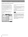
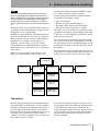
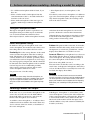
DM-24
Digital Mixing Console
to
EFFECTS MANUAL
Table of Contents
1 – Internal Effects on the DM-24
Patching and setting up effects .................. 3
Mono and stereo inputs ......................................... 4
Example 1 (Loop/insert setting with
1=mono input and 2=stereo input .......................4
Example 2 (Loop/insert setting with
1 & 2 both = stereo input) .....................................4
Example 3: (Loop/insert setting with
1 & 2 both = mono input) ......................................5
Example 4: 1/2 series (1=mono input,
2=stereo input) .......................................................5
4 – Antares speaker modeling
Selecting the speaker modeler .............................18
General parameters ...............................................18
INTYPE ..................................................................... 18
INPUT ....................................................................... 18
BYPASS .................................................................... 18
Source speaker types .................................18
Target speaker types .................................19
A few limitations ...................................................19
5 – TC Works Reverb
Effect send sources ...................................... 5
General parameters ...................................20
Aux 1 through 6 ........................................................5
Aux 1 through Aux 6 insert ......................................6
Buss 1 through buss 8 insert ....................................6
Stereo L, R insert .......................................................6
Assignable inserts 1 through 4 ................................6
INTYPE ..................................................................... 20
INPUT ....................................................................... 20
OUTPUT ................................................................... 20
MIX ........................................................................... 20
Effect 1-2 series ....................................................... 6
Setting up the effects units ........................ 7
Changing parameters .................................. 7
Storing your settings .............................................. 8
2 – Notes on using effects
Default snapshot settings ........................... 9
Using the internal effects as inserts (i) ...... 9
Using the internal effects as inserts (ii) ... 10
3 – Antares microphone modeling
Limitations ................................................. 11
Selecting the microphone modeler ...................... 12
Overall settings .......................................... 12
Input gain ................................................................12
Output level .............................................................12
Bypass ......................................................................12
Selecting the source microphone ............. 12
The bypass microphone model ............................ 13
Source microphone settings ................................. 13
Proximity ..................................................................13
Pattern .....................................................................13
Low-cut filter ...........................................................13
Selecting a model for output .................... 13
Model microphone parameters ............................ 14
Proximity ..................................................................14
Low-cut filter ...........................................................14
Response pattern ....................................................14
Preserve source settings ....................................... 14
Tube saturation ..................................................... 14
Microphone models ................................... 15
Updating microphone models .............................. 17
Balance controls .........................................20
I/R ............................................................................. 20
TAIL .......................................................................... 20
High-cut filter .............................................21
HICUT ....................................................................... 21
ATT ........................................................................... 21
Space editor ................................................21
SHAPE ...................................................................... 21
SIZE .......................................................................... 21
W-DIFF ..................................................................... 21
WIDTH ...................................................................... 21
Decay characteristics ..................................21
LOW, MID, HIGH ..................................................... 21
RANGE ..................................................................... 21
X-over ...................................................................... 21
Pre-delay settings .......................................22
INLEV ........................................................................ 22
REVLEV ..................................................................... 22
PREDLY .................................................................... 22
REVFEED .................................................................. 22
Conclusion ..............................................................22
Preset reverb settings ................................22
Ambience ................................................................. 22
Box ........................................................................... 22
Chamber .................................................................. 22
FX ............................................................................. 22
Tunnel ...................................................................... 22
Hall ........................................................................... 22
Drum ........................................................................ 22
Perc .......................................................................... 22
Plate ......................................................................... 22
Room ........................................................................ 22
6 – TASCAM effects
Common parameters .................................26
INPUT ....................................................................... 26
MIX ........................................................................... 26
OUTPUT ................................................................... 26
Effect parameters .......................................26
Preset effect settings .................................27
2 TASCAM DM-24 Effects
1 – Internal Effects on the DM-24
The DM-24 contains a number of high-quality effects
that you can use within your project, either while
recording, or on mixdown.
The effects available include:
•
•
•
•
•
•
•
•
•
Microphone modelling (single-channel)
Speaker modelling (two channels)
Chorus (two channels)
Delay (two channels)
Distortion (single-channel)
Guitar compression (single-channel)
Soft compression (two channel)
Phaser (two channels)
Pitch shifter (two channels)
•
•
•
•
Flanger (two channels)
De-esser (two channels)
Exciter (two channels)
Reverb (two channels)
Out of these, the two effects are available at any one
time in 44.1k or 48k sampling frequency mode. In
high sampling frequency modes (88.2k or 96k), only
one effect is available.
NOTE
The following combinations cannot be used: reverb +
reverb, reverb + speaker modeler.
In high sampling frequency mode, the reverb, microphone modeler and speaker modeler are unavailable.
Patching and setting up effects
All effect settings are managed using the EFFECT
key. This allows the assignment of sends and returns,
as well as the selection and parameter setting for the
effects.
There are two primary options, to use the effects
independently in loop or insert mode, or to use the
two effects in series, with the output of effect 1 feeding the input of effect 2 (similar to some multi-effect
units).
The first of these modes is known as the Loop/Insert
mode, and the second as the EFFECT1 EFFECT2 Series
mode.
Use the cursor keys to select the mode (either Loop/
Insert or EFFECT1 EFFECT2 Series), and the ENTER key
to confirm the choice.
The lower part of the screen contains a representation
of the two internal effect inputs and outputs. An
effect may have two inputs (L and R) and two outputs
(L and R). See “Mono and stereo inputs” on page 4
for more information.
However, this does not mean that there are two separate effect processors in each effect. It is possible to
use the two inputs of the effect processor “creatively”
(that is, have two completely separate feeds for the
left and the right inputs of the effect), but this is not
recommended.
We strongly suggest that only pairs of inputs (e.g.
stereo inserts, odd-even pair buss and aux inserts and
odd/even pairs of aux sends) are selected as stereo
inputs for the effects.
Use this screen to select the input sources for the
internal effects.
The choices available are:
Press the EFFECT key followed by soft key 1
(PATCH) to bring up the patch screen as shown here.
NOTE
When using the DM-24 in high sampling frequency
mode, only one effect is available, and only one effect
(EFFECT 1) is shown on this screen.
Effect source
Display shows
Aux sends 1 through 6
Buss 1 through 8 insert
Aux 1 through 6 insert
Stereo L, R insert
AUXx
BUSS1 INS SEND
AUXx INS SEND
ST-L PRESEND,
STR-R PRE SEND
ASGN INSx SEND
Assignable insert 1 through 4
Use the cursor keys, dial and ENTER key to set the
value for each input.
TASCAM DM-24 Effects 3
1 – Internal Effects on the DM-24—Patching and setting up effects
WARNING
Although it is theoretically possible to select both an
aux send and an aux insert as input sources for an
effect, a few seconds’ thought will show that this will
result in a feedback loop, resulting in possible damage
to equipment (and ears!). You should therefore avoid
making this type of setting.
A popup message appears to show that the assignment has been made.
NOTE
The same source cannot be selected twice to feed two
different effect inputs (except for the aux sends). A
popup message appears to warn of attempted duplicate assignments.
Any send/return assignments made to the effects will
override any assignments made to external send/return
insert loops.
The effect output destination cannot be selected here—
the destination of the effect outputs is determined by
the choice of the input source, and in the case of the
aux sends by the settings made in the I/O screens.
Mono and stereo inputs
The DM-24 internal effects are either single-channel
or two-channel, as listed at the start of this section.
Example 1 (Loop/insert setting with
1=mono input and 2=stereo input In this
At the top of the input/output patch section for each
effect, there is a field called INTYPE (input type).
example, the delay line is fed by a mono signal
source (for example a microphone) and the output is
spread between the left and right outputs.
In the case of single-channel effects, the only option
available is Mono.
In the case of dual-channel effects, there is a pair of
radio buttons: Stereo and Mono. Select one of these as
appropriate, depending on whether one mono source,
or a stereo pair of sources (e.g. a pair of aux sends)
will be used to feed the effect.
Once again, we recommend that only pairs of inputs
(e.g. stereo inserts, odd-even pair buss and aux
inserts and odd/even pairs of aux sends) are selected
as stereo inputs for the effects.
The number of outputs available for an effect
depends on a number of factors: the type of effect
currently selected, the mono/stereo input type currently selected, and the destination of the effect (for
instance, if effect 1 is patched in series with a single-channel effect used in effect 2, only one channel
is output from effect 1).
4 TASCAM DM-24 Effects
The stereo inputs to the plate reverb maintain the
image of the stereo source (for example, if a pair of
overhead mics has been set up to record a drum kit).
1 – Internal Effects on the DM-24—Effect send sources
Example 2 (Loop/insert setting with 1 & 2
both = stereo input) In this example, both
effects are used in insert mode. Busses 1 and 2 use a
effect 1 as a stereo phaser (this can be turned on or
off as needed for a creative effect).
Effect 2 (a chorus) is inserted into an input channel
(for example, a fretless bass) in order to thicken the
sound. In this example, because these effects are
being used by only one channel each, there is no need
to tie up the aux sends and returns, which can then be
used for other purposes.
Example 4: 1/2 series (1=mono input,
2=stereo input) In this example, the two effects
are put in series, with effect 1 (echo) taking a mono
mic signal and echoing it to the left and right channels.
The stereo compressor assigned to effect 2 is inserted
in the stereo output buss in order to limit the dynamic
range of the stereo outputs.
Example 3: (Loop/insert setting with 1 &
2 both = mono input) Here again, both effect 1
and effect 2 are used as inserts, but they both have
mono inputs.
Effect 1 (a distortion setting) is being used with a distortion effect, in order to achieve a distorted vocal
sound.
These echoes are then passed to the reverb, where
they are processed “in-place” to provide an interesting stereo effect (note that reversing these two effects
would produce echoed reverb—probably less desirable).
Effect send sources
Whether the effect (or in series mode, both effects
together) is used as a loop or an insert depends on the
source selected for the effect inputs.
The effect output with this setting is assigned to a
channel using the I/O screens (see “Signal sources”
on page 36 of the main manual).
Aux 1 through 6 When these are selected as
If a channel has already been assigned to take its
input from an internal effect, this channel is shown
effect input sources, the effect is placed in a loop.
TASCAM DM-24 Effects
5
1 – Internal Effects on the DM-24—Effect send sources
on the OUT section of the screen when the loop
assignment is made and is shown as Chxx (xx = 1
through 32). If no channel has been assigned, the display shows ---. If more than one channel has been
assigned as a return, the display shows ****.
Aux 1 through Aux 6 insert When these are
selected as effect input sources (AUXx INS SEND), the
effect becomes an insert-type effect.
This insert is made post aux send fader.
The outputs of the effect are automatically assigned
to the appropriate aux insert returns and shown as
AUX INS RETURN.
Buss 1 through buss 8 insert When these are
selected as effect input sources (BUSSx INS SEND), the
effect becomes an insert-type effect.
This insert is made post buss level fader.
The outputs of the effect are automatically assigned
to the appropriate buss insert returns and shown as
BUSS INS RETURN.
Stereo L, R insert When these are selected as
effect input sources (ST-L PRE SEND and ST-R PRE
SEND), the effect becomes an insert-type effect.
This insert is made pre stereo master fader.
The outputs are automatically assigned to the stereo
insert returns are shown as ST-L PRE RETURN and ST-R
PRE RETURN.
Assignable inserts 1 through 4 When these
are selected as effect input sources (ASGN INSx SEND),
the effect becomes an insert-type effect.
For these to be effective, the assignable send/returns
must be set to be inserts, not send/return loops (see
“Assignable sends and returns” on page 43 of the
main manual). If they have been set to send/return
loops, a popup message appears informing you of the
fact.
Note that when an assignment is made to these
inserts, the corresponding physical 1/4” jacks are no
longer available (these settings override the physical
jack insert assignments).
The outputs from the effects are sent to the assignable insert return. This is shown in the output assignment section of the effect as ASGN INSx RTN CH y if a
channel assignment has been made, or ASGN INSx RTN
--- if no assignment has been made.
Effect 1-2 series
When the two effects units are selected to act in
series, with effect 1 feeding effect 2, although both
effect 1 and effect 2 are shown on the screen, only the
inputs to effect 1 may be set.
The output(s) from effect 1 are automatically routed
to the input(s) of effect 2.
If the source of effect 1 is an aux send, the effect 2
output is assigned to a channel (set using the I/O
screen).
6 TASCAM DM-24 Effects
If the source of effect 1 is an insert, the output of
effect 2 defaults to the insert return as shown in the
output assignment section of effect 2.
The outputs from effect 1 are shown as EFFECT2 IN L
and EFFECT2 IN R, and the inputs to effect 2 are shown
as EFFECT1 OUT L and EFFECT1 OUT R (if effect 2 is a
dual-channel effect).
If channel 2 is set to output only a single channel, the
single output from effect 1 is labeled as EFFECT2 IN L
and if there is a single input to effect 2, this is labeled
EFFECT1 OUT L.
1 – Internal Effects on the DM-24—Setting up the effects units
Setting up the effects units
To use one of the internal effect units, press the
EFFECT key and then soft key 2 or soft key 3 (EFFECT
1 or EFFECT 2).
• The second holds preset TASCAM effect settings
(“Preset effect settings” on page 27).
Use the library screen to scroll through the list of different library entries in the selected bank.
See “Library functions” on page 99 of the main manual for full details regarding library functions.
NOTE
Although the preset library banks are named 1 and 2,
an effect from library bank 1 may be recalled for use
with effect 2, etc., as well as the other way round.
Remember, though, that when using effects in series,
effect 1 always feeds effect 2. If the effect settings are
recalled to the wrong effect, the sound may not be
quite what you expect (echoed reverb is rather different from reverbed echo, for example).
Next, use the EFF... LIB-> key (soft key 4) to enter the
effects library.
Use the cursor keys and ENTER key to select either
one of the two effect preset banks or the user effect
bank.
There are two preset library banks:
• The first bank holds the TC Works reverb preset
settings, as well as blank templates for the Antares
microphone and speaker modelers (“Preset reverb
settings” on page 22).
When you recall a library entry from the library, a
popup message appears confirming the selection.
When the EFFECT key is pressed, the effect screen
showing the values and parameters appropriate for
that particular type of effect is displayed.
Once an entry has been recalled, there is no way of
changing its type through the on-screen parameters.
You must reload an entry of another type from the
library in order to change the effect type.
NOTE
The points at which the effects are returned are set in
the I/O screens and are selectable in the same way as for
mic/line inputs, etc.
Changing parameters
The parameters of the entry are changed using the
cursor keys and PODs, dial and ENTER key, in the
same way as other parameters on the DM-24.
These parameter settings take place immediately
(that is, the effect of the change can be heard immediately after the parameter has been changed).
See the appropriate sections of this manual for details
of how the parameters change depending on the
effect type selected.
Essentially, there are two different types of effect: the
in-line type of processor, typically used in an insert
mode, and the send/return type, typically used in a
loop mode (aux send to channel return).
There are no hard and fast rules as to how these
should be used, though. If you wish to use the guitar
amplifier simulator to add an unusual sound to a
string quartet, you are of course free to do so!
Note how all effect screens have a pair of input
meters and a pair of output meters at the top left of
the screen so that the level can be properly adjusted.
The microphone modeler has (in the top row of
PODs) an input and an output level control.
The speaker modeler has (in the top row of PODs) an
input control.
The reverb and the other (TASCAM) effects all have
(in the top row of PODs) an input and output level
control, as well as a mix (wet/dry) control.
TASCAM DM-24 Effects
7
1 – Internal Effects on the DM-24—Changing parameters
NOTE
On account of unavoidable processing delays, it is recommended that the mix control be always set to 100%
(fully wet), as the original and processed sound may be
a few samples out of phase with each other, resulting in
audio artifacts if the two signals are mixed.
Storing your settings
When you have set up the parameters of an effect,
you can store it for further use in the user effects
library.
effect bank, or to overwrite an existing setting stored
in the library.
This saves you having to make the same settings
every time for a commonly-used microphone model,
for example.
While in the effect parameters screen, press soft key
4 (the EFF...LIB key) to bring up the library screen.
This allows you to scroll through the list of settings
and either save to an unused library entry in the user
Again, consult the main manual for details of how to
name and manage library entries.
8 TASCAM DM-24 Effects
2 – Notes on using effects
Because of the nature of the DM-24’s routing, a little
thought may be needed when assignments are made
on the effect patch page, as the DM-24 allows the
same signal to be routed to more than one channel
simultaneously.
does not happen accidentally, causing unexpected
and unwanted results.
This section provides some tips and pointers on how
to best set up the DM-24 in order to avoid any such
possible problems.
Although this kind of versatility is often desirable, it
is important to make sure that this kind of assignment
Default snapshot settings
The default mix snapshot returns the outputs from
effect 1 and effect 2 to channels 25/26 and 27/28
respectively.
In the same snapshot, assignable returns are assigned
to channels 29 through 32.
These settings are designed for the use of the internal
sends with the aux sends and returns, and external
effects with the hardware insert loops (assignable
sends and returns). If you are making changes to use
the internal effects or assignable sends and returns as
inserts or assignable inserts, a little work must be
done, using the assignment screens.
Using the internal effects as inserts (i)
In this example, effect 1 will be used as an insert on
buss 2.
To do this, the effects returns must first be removed
(de-assigned) from channels 25 and 26.
With the SHIFT indicator lit, press the I/O key until
the screen allowing assignment of channels 17
through 32 appears (or use soft key 2 to access the
screen).
You should set these inputs to some “harmless” setting which will not conflict with any other setting
that is already in use. A useful source here might be
one of the digital inputs (if you are not already using
them).
NOTE
It is possible to assign the same source to more than one
channel. There are obvious dangers associated with
such an action, so we do not recommend that you do
this.
Next, return to the effect patch page (press the
EFFECT key until the patch screen appears):
Select BUSS2 INS SEND as the input source for effect
1. When you do this, the output for effect 1 will automatically change (BUSS INS RETURN).
If you had not removed the effect returns from channels 25 and 26 before assigning the buss insert send, the
effect return would have been routed to these channels
as well as to the buss insert return (as in the screen shot
above).
TASCAM DM-24 Effects 9
2 – Notes on using effects—Using the internal effects as inserts (ii)
Using the internal effects as inserts (ii)
In this section, we look at how you change the
default settings to use effect 2 as a stereo input processor using assignable send/return inserts 1 and 2.
The insert will be assigned with channels 1 and 2.
Again, use the I/O key (the SHIFT indicator must be
lit) to access the 17 through 32 screen (soft key 2),
allowing the de-assignment of the assignable returns
1 and 2 from channels 29 and 30.
Again, pick a “safe” or harmless option of an input
that you are not using.
Next, the assignable sends and returns have to be
changed from their send/return loop setting to an
insert setting.
Press soft key 4 to access the assignable output
screen:
Assignable send/returns 1 and 2 should be set to the
insert mode.
The insert channels (that is, the channels on which
the inserts will work) should be set to channels 1 and
2 (of course, you are free to change this if you want
to use other channels with this effect.
In the EFFECT patch page, select Stereo as the input
type for effect 2.
Change the input source to ASGN INS 1 SEND (CH 1)
for the left input and ASGN INS 2 SEND (CH 2) for the
right input.
NOTE
It is important that these operations are carried out in
the order here.
If you try to route these assignable inserts to effect 2
(on the effect patch screen) without changing the
assignable send/return mode first, a popup message
appears telling you that the assignable insert is in the
send/return mode.
If you then try to correct this by changing the send/
return mode to the insert mode, another message
appears, informing you that return 1 is currently
assigned to channel 29.
10 TASCAM DM-24 Effects
3 – Antares microphone modeling
NOTE
All names of microphone manufacturers and microphone model designations appearing in this manual
and on the DM-24 are used solely to identify the microphones analyzed in the development of the digital
models and do not in any way imply any association
with or endorsement by any of the named manufacturers.
This effect allows you to model the characteristics of
a particular model of microphone and apply it to the
microphone you are actually using.
In addition to reproducing the sonic characteristics of
the modeled microphones, this effect also allows for
the reproduction of certain options on the modeled
microphone (for example, low cut filters, etc.).
Typically, you will want to “re-record” already
recorded tracks with another microphone model at
the mixdown stage, as this allows you to experiment
with settings.
When you use the modeler at the mixdown stage,
though, it is important that you have clear and
detailed notes of the microphone conditions which
were used to make the original recording.
Among other useful information which should be
noted when the recording is made:
•
•
•
•
Type of microphone
Distance of source from microphone
Any filter settings made on the microphone
The response pattern used when recording
Of course, it is also possible to record directly using
one physical microphone and modelling another, but
in this case, it is more difficult to experiment, and to
make changes afterwards.
Note that when we talk about the microphone modeler, we use the term source microphone to describe
the actual physical device and the description of it in
the modeler, and model to describe the target, virtual
microphone.
The diagram below gives an approximate idea of how
the parameters available interact with each other (signal flow may be taken as being from left to right).
Preserve source
(bass and treble)
Input level
Source mic type
Model mic type
Source mic
proximity
Model mic
proximity
Source mic
low-cut
Model mic
low-cut
Source mic
response pattern
Model mic
response pattern
Tube saturation
Output level
Limitations
Be aware, though, that while the microphone modelling will produce excellent effects, it is not capable of
producing something from nothing. In other words, a
poor recording made with a cheaper source microphone will not be magically transformed into a good
recording, if an expensive microphone model is
selected—it will still sound like a poor recording, but
made with an expensive model.
Nor can the microphone modeler magically restore
missing parts of the signal which are missing because
of the limitations of the source microphone. If a
cheap microphone with limited bass response is used
to record, using an expensive model with the microphone modeler will not put the missing bass back
into the recording.
TASCAM DM-24 Effects 11
3 – Antares microphone modeling—Overall settings
Excessive frequency boosting can occur if processes
intervening between the microphone and the modeler
produce noise. This noise will be excessively
boosted, especially if the filtering on the microphone
and the recording process has accentuated this.
Polar response patterns can be simulated, but cannot
automatically change the pattern of the source microphone. For example, if a recording has been made
using a microphone with a cardioid response pattern,
setting the model’s pattern to omnidirectional will
not automatically turn the source microphone into an
omnidirectional microphone (and add the room
ambience that would be present if the microphone
actually was an omnidirectional one).
Likewise, if a source microphone has a particular
off-axis response, this individuality will be retained
even if a different model is selected.
NOTE
The microphone modeler can only be used with the L
input and output of either effect 1 or effect 2. It is not
possible to use the microphone modeler to process two
channels at the same time using one effect.
The microphone modeler is not available in high sampling frequency mode.
Selecting the microphone modeler
Recall the preset library entry 1-100 in order to load
the microphone modeler.
See “Setting up the effects units” on page 7 for further details.
Overall settings
These settings apply to the overall effect (not to the
source or model microphones individually).
ment in dynamic range that would result if this operation was to take place on an all-analog system.
Input gain This (INPUT) allows you to set the relative gain for the input source (top row, POD 2).
Output level This (OUTPUT) allows the overall
Start at 0dB, but you may want to increase the level
slightly to increase the amount of saturation available
to the processor. The signal may be cut by a value up
to –30 dB and boosted by up to 12 dB.
NOTE
Increasing this input level to obtain the highest possible
non-clipping meter level does not result in the improve-
output gain from the modeler to be adjusted from
0 dB to –12 dB.
Bypass This allows the whole of the microphone
modeler to be bypassed for A-B comparisons. It is
not the same as selecting the bypass microphone
model (“The bypass microphone model” on
page 13), which is a “neutral” microphone model for
either source or output (but it is the same as selecting
it for source and output).
Selecting the source microphone
Move the cursor to the Source Microphone, selecting
the model using POD 1.
The manufacturer name is given at the top left of the
box, and the model at the bottom right.
There may be two listings for a particular source
microphone model, one of them ending with a -w.
This means that this is the model of microphone with
a supplied windscreen (thereby affecting the acoustic
characteristics of the microphone).
There may also be a (m1) or (m2) following the
microphone name. These refer to different examples
of the same kind of microphone. Pick the one which
is most appropriate for your particular microphone.
If you do not have a microphone listed in the list of
source microphones provided:
12 TASCAM DM-24 Effects
3 – Antares microphone modeling—Selecting a model for output
• Use a different microphone which is listed, if you
have one.
• Select a similar model of microphone from the
same manufacturer; that is, one with similar characteristics to the one in use.
• Select another microphone of the same type (for
example, another large condenser microphone,
etc.).
• Select Bypass (that is, no microphone) as the
source.
Note that if you do select a microphone of a different
type to the actual microphone, though you will probably obtain acceptable results, the resulting sound
will not be 100% accurate.
The bypass microphone model
The bypass microphone model is equivalent to no
microphone being used. This may be useful in the
case of electric instruments which have been
direct-injected (that is, with no microphone involved)
and where the model microphone is to be used to
provide a distinctive sound for these instruments.
Although this may not produce an absolutely realistic
model of the model microphone, it will almost certainly produce an interesting sound.
Source microphone settings
In addition to the type of microphone used as the
source microphone, the modeler needs to know a few
more things before it can achieve the best results:
Proximity This is the average distance of the sound
source from the microphone when the recording is
made. The distance is measured in inches (1 inch =
2.54cm). If this is not set, then the “proximity effect”
(an artificial boost in bass frequencies at close range)
may not be properly compensated, and the sound will
be unnatural. Note that microphones with an omnidirectional response do not exhibit this proximity
effect, and any settings made here with an omni
source microphone will have no effect.
Use pod 2 on row 3 for this setting.
NOTE
As the source moves away from the microphone, an
amount of ambient room tone is added to the recording. The microphone modeler cannot add the room
tone, but a little reverb added to the signal may help
here.
Pattern The pattern of the source mic, if selectable,
should be echoed in this setting. If the source mic is
fixed-pattern, no selection is possible here, and the
display shows None here. Use POD 3 on row 3.
Low-cut filter Many microphones have a bass cut
filter. If this filter has been set on the real physical
source microphone, this setting should be made on
the source microphone of the modeler as well.
This is done using POD 4 on row 3.
The actual name of this filter varies according to the
actual name on the physical microphone, and will not
exist at all if the mic does not actually have such a filter fitted (the display shows None).
NOTE
The modeler assumes that the source was recorded
on-axis. Since there is no way to tell the modeler about
the actual position of the source relative to the microphone, the modeler cannot compensate for frequency
differences, etc. caused by off-axis placement of the
source.
Selecting a model for output
In the same way as you selected a microphone as the
source mic, move the cursor to the Model Microphone field (POD 1, bottom row), and select the
model of the microphone to be modeled.
As with the source microphone, a -w indicates that a
windscreen has been added to the model. There may
also be variants of the base model, as described for
the source microphone.
If the Bypass “microphone” is selected here, and a
source microphone is selected, the effect will be that
of the source microphone’s characteristics. If Bypass
is selected both for the source and the model, the
final result of the modeler will be the input source,
with the addition of any tube saturation added by the
modeler (see below).
TASCAM DM-24 Effects
13
3 – Antares microphone modeling—Selecting a model for output
Model microphone parameters
As with the source microphone, there are a number
of different additional parameters available which
can be set.
model (if there is no filter available on the actual
microphone being modeled, the model does not have
a filter available, and shows None).
Proximity As with the source microphone, the
Note that this filter is not a straight low-cut filter—it
is a representation of the actual filter incorporated on
the physical microphone being modeled.
model can also have a proximity value set (in inches
again). Use POD 2, bottom row.
When used with the model, it will affect the final
character of the sound, as if the source was the specified distance from the model microphone when the
recording was made.
Note that this setting cannot add “room tone” to a
recording, even though the further away a real microphone is from a sound source, the more room tone is
added to the final recording.
NOTE
Since omnidirectional microphones do not exhibit the
proximity effect, if the model microphone is omnidirectional or has its pattern set to omnidirectional, this setting will have no effect.
Low-cut filter If the modeled microphone is fitted
with a low-cut filter, this is also available on the
NOTE
Although it is not a hard and fast rule, it is a good idea
to include the low-cut filter on the model if the filter
has been used on the source microphone.
Response pattern As with the source microphone, the model can also take different response
patterns (if the actual physical microphone being
modeled is capable of this kind of flexibility—otherwise None is displayed for this option). Pod 3, bottom
row is used here.
Remember that the modeler cannot spontaneously
recreate missing data, so if a recording has been
made with the source off-axis, this setting cannot be
used to add the frequencies that were lost by the
off-axis recording.
Preserve source settings
These settings allow you to make a hybrid microphone, dividing the microphones (both source and
model) into their treble and bass components.
In this way, the two halves of the microphones can be
“sandwiched” together to produce unusual creative
effects.
Usually, however, you will want to keep the desirable
characteristics of the source microphone (for example, a bass response) and eliminate the undesirable
side (say, a poor treble response).
First, make all the appropriate source microphone
settings. Bypassing the system is not a good idea
here, as it will not have any useful effects.
Use the Preserve Source controls (PODs 1 and 2, second row) to select the portion of the source microphone that you want to keep (either the treble portion
on the bass portion).
Keeping the original shows PRESERVE, and sending
the signal through the processor shows PROCESS.
When a portion of the source microphone is preserved in this way, it overrides the corresponding
portion of the model microphone.
Obviously preserving the source for both the bass
and treble portions of the source is not terribly useful
(though the proximity settings for both the source
and the model remain effective).
Tube saturation
One of the more attractive aspects of older studio
equipment is tube (valve) saturation. The microphone
modeler provides you with a way to simulate this on
the output side of the modeler.
Pick a value of the GAIN which suits your ears. The
maximum value which may be set here is +10dB
(0.1 dB steps). The signal to be recorded must there-
14 TASCAM DM-24 Effects
fore be at a level which is at least greater than –10dB
for this to have any effect.
Use POD 4, second row to set the amount of gain.
However, you should take care that the input level is
not increased to the point where digital distortion
occurs.
3 – Antares microphone modeling—Microphone models
You may need to “juggle” the values of the input
level and the drive gain to achieve the most satisfactory results for this parameter.
Microphone models
The microphone models listed here are available for
the DM-24 microphone modeler.
In the display, typically parameters and names are
shown as given here, but the spacing of words on
screen may sometimes differ from those given in the
table.
Number Microphone Maker
0
1
2
3
4
5
6
7
8
9
10
11
12
13
14
15
16
17
18
19
20
21
22
23
24
25
26
27
28
29
30
31
32
bypass mic
AKG
Alesis
Audio Technica
Audix
Beyer
Brauner
B&K
Microphone name
The microphone response patterns are shown in
uppercase, as follows: CARDIOID (cardioid), OMNI
(omni-directional), HYPERCARDIOID (hyper-cardioid), FIGURE 8 (figure-of-8), WIDE CARDIOID (wide
cardioid), w A98SPM (w A98SPM) and MS (MONO
SIM) (MS (mono sim)).
Low cut
C 1000S
C 12A
C 3000
C 4000 B
C414
C 414B-ULS (mod1)
C 414B-UHS (mod2)
C 414B-UHS Gold
C 414B-ULS Gold (w)
C 460 B, CK 61-ULS
D 122 (1)
D 122 (2)
D 790
AM61
3525
4033
4047 sv
4050
4055
4060
853Rx
ATM11
ATM31
D4
OM2
OM3-xb
OM5
CK-703
M-500 LE Classic
MC-834
VM1
none
none
none / -7 dB/oct / -12dB/oct
off / on
0 Hz / 100Hz
0 Hz / 75Hz / 150Hz
0 Hz / 75Hz / 150Hz
0Hz / 75Hz / 150Hz
0Hz / 75Hz / 150Hz
0Hz / 75Hz / 150Hz
0Hz / 50Hz / 70Hz / 150Hz
none
none
none
off / on
off / on
off / on
off / on
off / on
none
none
none
none
none
none
none
none
none
off / on
none
LIN / 80Hz / 160Hz
none
4007
none
Pattern
none
none
cardioid / omni
cardioid / hypercardioid
cardioid / hypercardioid / omni
cardioid
cardioid / hypercardioid /figure 8 / omni
cardioid / omni
cardioid / hypercardioid /figure 8 / omni
cardioid / hypercardioid /figure 8 / omni
none
none
none
none
none
none
none
none
cardioid / fugire8 / omni
none
none
none
none
none
none
none
none
none
none
none
none
cardioid / hypercardioid / wide cardioid / figure 8 /
omni
none
TASCAM DM-24 Effects
15
3 – Antares microphone modeling—Microphone models
Number Microphone Maker
33
34
35
36
37
38
39
40
41
42
43
44
CAD
Coles
Earthworks
ElectroVoice
Gefell
Microphone name
Low cut
95Ni
C400S
Equitek E100
Equitek E200
Equitek E350
VSM1 (mod 1)
4038
TC-30K
Z30X
N D 357
PL20
UMT 800
none
none
off / on
off / on
off / on
off / on
none
none
none
none
off / on
off / on
45
46
47
48
49
50
Groove
Lawson
Manley
Tubes MD-1
L47
Reference Gold
KM 184
KM 184(w)
M 149
none
none
none
none
none
20Hz / 40Hz / 80Hz / 160Hz
51
52
53
54
55
56
57
58
Neumann
TLM 103
TLM 193
U 47
U 87 GOLD
U 87
MC 012
MK-319
BK-5A
none
none
none
off / on
off / on
none
off / on
M (music) / V1 (voice) / V2
(voice)
none
off / on
off / on
none
none
none
none
M (music) / 3 / 2 / 1 / S
(speech)
M (music) / 3 / 2 / 1 / S
(speech)
59
60
61
62
63
64
65
66
67
Oktava
RCA
Rode
Royer
Sennheiser
NT1
NT2
NT2(w)
NTV
R-121
E 609
E 835S
MD 421
MD 441
16 TASCAM DM-24 Effects
Pattern
none
none
none
cardioid / figiue8 / omni
cardioid / figure8 / omni
none
none
none
none
none
none
cardioid / hypercardioid / wide cardioid / figure 8 /
omni
none
none
cardioid / figure 8 /omni
none
none
cardioid / hypercardioid/wide cardioid / figure 8 /
omni
none
none
cardioid / omni
cardioid / figure 8 /omni
cardioid / omni
cardioid / hypercardioid / omni
none
none
none
cardioid / omni
cardioid / omni
none
none
none
none
none
none
3 – Antares microphone modeling—Microphone models
Number Microphone Maker
68
69
70
71
72
73
74
75
76
77
78
79
80
81
82
83
Shure
Sony
Telefunken
Microphone name
Beta 52
Beta 57A
Beta 87A
Beta 98D-S
KSM32
SM57
SM58
SM7A
SM81
SM98A
VP88 (mono sim)
C37P
C48
C800G
C800G(w)
TELE U47
Low cut
none
none
none
none
LC 0 / LC 1 / LC 2
none
none
LC off Mid off / LC off Mid on /
LC on Mid off / LC on Mid on
LC 0 / LC 1 / LC 2
off / on
off / on
M / M1 / V1 / V2
M (music) / V (voice)
none
none
none
Pattern
none
none
none
none
none
none
none
none
none
w A98SPM
MS (mono sim)
none
cardioid / figure 8 / omni
cardioid / omni
cardioid / omni
cardioid / omni
Updating microphone models
The modeler provides up to 100 models of microphone. More may be made available in the future
through the TASCAM Web site.
Consult your dealer for availability.
TASCAM DM-24 Effects
17
4 – Antares speaker modeling
In the same way that microphones can be modeled,
the DM-24 allows for the modeling of speakers.
Once again, it is important to remember that it is not
possible to instantly transform a pair of low-end
near-field monitors into a pair of expensive,
top-of-the-line monster monitors (even modern technology has its limits), but it can be useful for simulating some of the speaker types on which your final
project will be played, and for which you may not
have space in your control room (or where it may be
inconvenient to reproduce the sound—for example,
not many people will wish to purchase a SUV merely
for the acoustical properties of the interior!).
This speaker modeler can be inserted anywhere in the
signal chain, but obviously it is more useful if it is
selected as an insert in the main stereo outputs.
The technique for using this is similar to the microphone modeler, but not so complex.
Basically, you define a set of source speakers (the
real speakers that you are listening to) and a set of
target speakers (the ones that you wish to model).
NOTE
Due to technical limitations, if the speaker modeler is
selected as one effect, the reverb cannot be selected as
the second effect.
It is also not available in high sampling frequency
mode.
Selecting the speaker modeler
Recall the preset library entry 1-101 in order to load
the speaker modeler.
See “Setting up the effects units” on page 7 for further details.
General parameters
There are three general settings which are all set
using the top row of PODs.
to a mono signal comprised of the L and R output
signals added together.
INTYPE stands for input type. There are four
INPUT the input level can be adjusted (in 1 dB
steps) from –30 dB to +6 dB.
options here: Stereo, L mono, R mono and LR mono.
The first three explain themselves, but the last refers
BYPASS the whole of the speaker modeler effect
can be turned on and off with this parameter.
Source speaker types
The source speakers which may be selected are
generic types of speaker, not individual models.
• Mid Field Studio
• Near Field (better quality than the “cheap” model)
The different selections available (pod 2, bottom
row) are:
• Pro Near Field (more expensive than the other models here)
• Bypass speaker (as if there was no output speaker
connected to the DM-24)
• Cheap Near Field (for “cheap”, read “low-cost, but
acceptable performance”, but that is too long to fit
on the display!)
• Large Studio (dedicated studio monitors)
Choose the setting which you feel comes closest to
your set of speakers.
18 TASCAM DM-24 Effects
You can test the source model by selecting the Bypass
type for the target speaker and changing between the
different models, making A-B comparisons with the
whole effect bypassed in order to achieve the closest
match.
4 – Antares speaker modeling—Target speaker types
Target speaker types
The speakers modeled here are generic, rather than
reproducing a particular make or model of speaker.
They represent a wide range of speaker types on
which your material may eventually be played.
• Bypass speaker (no model for the output speaker)
• Boombox 1 (one type of “boombox”)
• Boombox 2 (another variation on the boombox
theme)
• Car Sedan (an average car sound system)
• Car SUV (the kind of sound you might expect from
an SUV sound system)
• Compact Stereo (domestic stereo system, but small
speakers)
• Computer Speaker (useful for multimedia sound
mixes)
• Large Home Studio (good quality domestic/semi-pro
speakers)
• Mid Sound Reinforcement (not necessarily
top-of-the-range, but good-quality sound reinforcement)
• Small Home Studio (smaller speakers intended for
the musician/home recordist)
• TV (typical TV speaker sound)
Use POD 4 on the bottom row to select the speaker
type.
A few limitations
Once again, it is necessary to emphasize that you
cannot turn a poor-quality set of speakers into an
expensive pair of monitors.
However, what you can do is to reproduce the tonal
characteristics of a certain type of speaker and environment, allowing you to “field-test” your project for
a particular purpose without even changing your
speaker system.
TASCAM DM-24 Effects
19
5 – TC Works Reverb
The TC Works reverberation built into the DM-24 is
a sophisticated reverb system, allowing you to simulate many different kinds of acoustic environment.
Most common (and a few less common) parameters
can be edited, allowing fine control of the whole
sound.
Early
reflections
Maximum decay time
Initial
level
INLEV)
Tail
Reverb level
(REVLEV)
HIGH
Pre-delay
(PREDLY)
MID
LOW
Reverb
feed
(REVFEED)
NOTE
Due to technical limitations, if reverb is selected as one
effect, the reverb or speaker modeler cannot be
selected as the second effect.
It is also not available in high sampling frequency
mode.
General parameters
There are three general settings which are all set
using the top row of PODs.
INTYPE stands for input type. There are four
options here: Stereo, L mono, R mono and LR mono.
The first three explain themselves, but the last refers
to a mono signal comprised of the L and R output
signals added together.
INPUT the input level can be adjusted from Off, and
then (in 5 dB steps) from –140 dB to –60 dB, (in
1 dB steps) from –60 dB to –20 dB and (in 0.1 dB
steps) from –20 dB to 0 dB.
OUTPUT The output level can be adjusted from Off,
and then (in 5 dB steps) from –140 dB to –60 dB, (in
1 dB steps) from –60 dB to –20 dB and (in 0.1 dB
steps) from –20 dB to 0 dB.
MIX Adjust the wet/dry mix from 0% (dry) to 100%
only reverb) in 101 1% steps.
Balance controls
There are two balance controls on the second POD
row (BALANCE).
right balance of these reflections from 50 through 0 to
50.
I/R This stands for “Initial Reflections” (sometimes
called Early Reflections”). POD 1 controls the left/
TAIL This stands for “reverb tail”—the final decay
20 TASCAM DM-24 Effects
of the reverb sound. POD 2 controls the left/right balance of these sounds from 50 through 0 to 50.
5 – TC Works Reverb—High-cut filter
High-cut filter
This filter can be used to cut off the upper frequencies of the reverb signal.
Use PODs 3 and 4 on row 2 of the screen.
ATT Short for “attenuation”—the amount by which
the high-cut filter cuts the upper frequencies. Use
POD 4 to set this value from –40.0 dB to 0 dB in
0.1 dB steps.
HICUT Sets the frequency at which the filter operates. Use POD 3 to select a value. The lower limit is
20 Hz, and the higher limit is 16 kHz.
Space editor
These four parameters allow you to set the basic
reverb type (row 3, labeled SPACE EDITOR).
SHAPE allows you to set the basic shape of the simulated room in which the sound is being reflected to
produce the reverberation effect.
Turn POD 1 to select from the following list (a small
representation of the room shape appears on the left
of the screen as you make these changes):
• HALL—a hall-shaped room (basically a cube)
• H.SHOE—(horseshoe) a room where one wall is flat,
and the other walls curve round.
• PRISM—a prism-shaped space with two parallel
walls focusing down to a wedge (similar to many
auditoria).
• FAN—even more wedge-shaped than the prism setting.
• CLUB—a T-shaped space, with a recessed stage
area.
• SMALL—a smaller, more intimate version of the
cube.
SIZE The size of the space. Units are arbitrary, and
may be set from 0.04 to 4.0 in the following steps:
0.04, 0.05, 0.06, 0.08, 0.10, 0.13, 0.16, 0.20, 0.25,
0.32, 0.40, 0.50, 0.63, 0.80, 1.0, 1.3, 1.6, 2.0, 2.5, 3.2,
4.0.
W-DIFF Wall diffusion—the “liveness” of the room
space, and the amount that the sound is scattered. Set
a value from –50% to +50% I 1% steps.
WIDTH Not, strictly speaking, the width of the simulated room, but the stereo width of the reverb signal
(which is affected by the width of the room). Set
from 0% (mono point source) to 100% (full width) in
1% steps.
Decay characteristics
The decay can be set for three bands independently,
allowing, for example, the treble portion of the sound
can continue to reverberate after the bass and mid
sounds have decayed, giving a bright quality to the
reverb.
The crossover points for the three bands can be set
independently.
Use the four pods in row 4 and the two pods in row 5
(labeled DECAY) to set the band times, as well as a
“scale” which allows fine-tuning of the times without
having to turn the PODs an excessive number of
times.
LOW, MID, HIGH Each of the three bands can be
set independently, in a range from 0.25 s to 9.99 s
and from 10.0 s to 64 s (1024 steps in total).
RANGE The overall range for these three bands
(and therefore the number of times the PODs must be
turned to set a value) an be set to one of three values:
4 s, 16 s and 64 s.
X-over The two crossover frequencies to divide the
sound spectrum into three bands can be set. Each of
these frequencies can be set between values of 20 Hz
and 16 kHz. Use PODs 1 and 3 on row 5 to set these
values.
TASCAM DM-24 Effects
21
5 – TC Works Reverb—Pre-delay settings
Pre-delay settings
The bottom row of the screen allows different delay
settings to be made.
Use POD 2 to set this value from Off, through –140 dB
to 0 dB.
See the diagram above for details of exactly what
these settings change.
PREDLY This is the pre-delay portion of the reverb.
INLEV This is the initial level of the early reflections.
Use POD 1 to set this value from Off, through
It describes the time from the initial sound to the first
of the initial reflections.
Use POD 3 to set this value from 0 ms to 160 ms in
1 ms steps.
–140 dB to 0 dB.
REVFEED This is the time separating the feed from
REVLEV This is the level at which the decay “tail”
the initial reflections to the “tail” part of the reverb.
portion of the reverb starts.
Use POD 4 to set this value from 0 ms to 100 ms in
1 ms steps.
Conclusion
Although the array of parameters and options for this
reverb may seem a little baffling at first, compared
with some other units, a little experimentation will
soon make it clear what the different parameters
actually control in terms of the sound produced.
The preset library entries provide useful starting
points for your own experiments, allowing you to
either simulate real reverb situations, or to invent
imaginary spaces with their own, distinctive, reverberation characteristics.
Preset reverb settings
The English names give an idea of the kind of sound
that can be obtained from these settings.
Hall settings give the sound of larger enclosed
spaces. There is a range of hall settings provided,
with different acoustical characteristics, including
“church” and “cathedral” settings.
Ambience settings basically give a feeling of life,
Drum settings are specifically tailored for use with
These settings are all stored in the first preset effects
library.
without a definite reverb.
Box settings are smaller or and typically have a
rather “live” sound.
drum instruments. Of course, they can be used with
other instruments and sources, but they may not be so
effective as when they are used with drum sources.
Perc settings are suitable (but not exclusively) for
Chamber settings provide a sound a little like a
room type of reverb.
use with percussion instruments and percussive
sounds.
FX settings provide a special effect, which may not
Plate Settings reproduce the sound of a vintage
sound totally natural, but may have a useful place in
your project.
plate reverb unit.
Tunnel settings provide the image of a long narrow
live space.
Number
Name
LCD indication
000
Ambience - Bright 1
Ambi-Bright 1
001
Ambience - Bright 2
Ambi-Bright 2
002
Ambience - Bright 3
Ambi-Bright 3
003
Ambience - Dark
Ambi-Dark
22 TASCAM DM-24 Effects
Room settings provide the effect of a smaller,
tighter space than a hall.jcASCAM effects
5 – TC Works Reverb—Preset reverb settings
Number
Name
LCD indication
004
Ambience - Midnight
Ambi-Midnight
005
Ambience - Mornin' Vocal
Ambi-MorninVocal
006
Ambience - Soft 1
Ambi-Soft 1
007
Ambience - Soft 2
Ambi-Soft 2
008
Ambience - Space
Ambi-Space
009
Box - Bright
Box-Bright
010
Box - Dark
Box-Dark
011
Chamber - Large, Dark
Chmb-Large,Dark
012
Chamber - Small
Chmb-Small
013
Chamber - Small, Dark
Chmb-Small,Dark
014
Chamber - Very Small
Chmb-Very Small
015
FX - Big Barrel Space
FX-BigBarrelSpce
016
FX - Big Pre Delay Slap
FX-BigPreDlySlap
017
FX - Bright Cymbals
FX-BrightCymbals
018
FX - Drum Boom Slap
FX-DrumBoom Slap
019
FX - Dry After Taste
FX-DryAfterTaste
020
FX - Icy Shower
FX-Icy Shower
021
FX - Lost in Space
FX-Lost in Space
022
FX - Neighbor (Hallway)
FX-NeighborHallw
023
FX - Neighbor 2 (Floor)
FX-NeighborFloor
024
FX - Not so Dry After Taste
FX-NotsoDryAfter
025
FX - Short Non-Lin Like
FX-Short Non-Lin
026
FX - Slap Back
FX-Slap Back
027
FX - Steel Works
FX-Steel Works
028
FX - Steel Works 2
FX-Steel Works 2
029
FX - Subtle Slapback
FX-SubtleSlapbac
030
FX - Take Off
FX-Take Off
031
FX - Tight Bounce Around
FX-Tight Bounce
032
FX - Ultra Bright
FX-Ultra Bright
033
FX - Under The Surface
FX-Under Surface
034
FX - Wet After Taste
FX-WetAfterTaste
035
FX - Wet After Taste w/Rain
FX-W.A.T w/Rain
036
FX - Wood Floor
FX-Wood Floor
037
Tunnel - Bright
Tunn-Bright
038
Tunnel - Dark
Tunn-Dark
039
Tunnel - Tube
Tunn-Tube
040
Hall - Big Bright
Hall-Big Bright
041
Hall - Big Clear
Hall-Big Clear
042
Hall - Big Predelayed
Hall-BigPredelay
043
Hall - Big Warm
Hall-Big Warm
TASCAM DM-24 Effects
23
5 – TC Works Reverb—Preset reverb settings
Number
Name
LCD indication
044
Hall - Cathedral 12s
Hall-Cathdral12s
045
Hall - Cathedral 7s
Hall-Cathedral7s
046
Hall - Church
Hall-Church
047
Hall - Dome
Hall-Dome
048
Hall - Huge Clear
Hall-Huge Clear
049
Hall - Huge Warm
Hall-Huge Warm
050
Hall - Last Row Stadium Con
Hall-LastRowStdm
051
Hall - Lush Ballad
Hall-Lush Ballad
052
Hall - Medium Bright
Hall-Med.Bright
053
Hall - Medium Clear
Hall-MediumClear
054
Hall - Medium Warm
Hall-Medium Warm
055
Hall - Outside the Stadium
Hall-OutsideStdm
056
Hall - Small Bright
Hall-SmallBright
057
Hall - Small Clear
Hall-Small Clear
058
Hall - Small Warm
Hall-Small Warm
059
Hall - Stage
Hall-Stage
060
Hall - Warm Vocal Hall
Hall-Warm Vocal
061
Drum - Boom Room
Drum-Boom Room
062
Drum - Drum Booth
Drum-Drum Booth
063
Drum - Huge Low Tubular
Drum-HugeLowTubu
064
Drum - Low Tubular
Drum-Low Tubular
065
Drum - Snare Hall
Drum-Snare Hall
066
Drum - Snare Room
Drum-Snare Room
067
Drum - Subtle Kick Boom
Drum-SubtleKick
068
Perc - Big Bright
Perc-Big Bright
069
Perc - Big Clear
Perc-Big Clear
070
Perc - Big Warm
Perc-Big Warm
071
Perc - Medium Bright
Perc-Med.Bright
072
Perc - Medium Clear
Perc-MediumClear
073
Perc - Medium Warm
Perc-Medium Warm
074
Perc - Small Bright
Perc-SmallBright
075
Perc - Small Clear
Perc-Small Clear
076
Perc - Small Room
Perc-Small Room
077
Perc - Small Warm
Perc-Small Warm
078
Plate - Big Bright
Plat-Big Bright
079
Plate - Big Clear
Plat-Big Clear
080
Plate - Big Warm
Plat-Big Warm
081
Plate - Tight
Plat-Tight
082
Room - Bathroom
Room-Bathroom
083
Room - CD Master
Room-CD Master
24 TASCAM DM-24 Effects
5 – TC Works Reverb—Preset reverb settings
Number
Name
LCD indication
084
Room - Dark & Mellow 5 sec
Room-Dark&Mellow
085
Room - Dry House
Room-Dry House
086
Room - Empty Garage
Room-EmptyGarage
087
Room - Empty Room
Room-EmptyRoom
088
Room - Empty Room, Small
Room-EmptyRoom S
089
Room - Large Garage
Room-LargeGarage
090
Room - Percussion Room
Room-Perc Room
091
Room - Small
Room-Small
092
Room - Small Damped Room
Room-S Dmp Room
093
Room - Small Yet Big
Room-SmallYetBig
094
Room - Small Yet Big w/Pre
Room-S.Y.B w/Pre
095
Room - Stage
Room-Stage
096
Room - Vocal Booth
Room-Vocal Booth
097
Room - Vocal Dry
Room-Vocal Dry
098
Room - Vocal Room
Room-Vocal Room
099
Room - Vocal Room 2
Room-Vocal Room2
These are not reverb settings, but this is the way in which the microphone and speaker modelers are selected
100
Antares AMM-1
Antares AMM-1
101
Antares SP modeler
Antares SP Model
TASCAM DM-24 Effects
25
6 – TASCAM effects
The general effects provided within the DM-24 as
described in “Internal Effects on the DM-24” on
page 3 may be used either as in-line inserted effects,
or as part of an effect loop, using aux send and
returns.
There are no hard and fast rules as to how these
effects can be used, but on the whole, any effect
where there is a wet/dry level is suitable for use
within effect loops, and the others are suitable for use
as insert processors.
Common parameters
There are three parameters on the top row of the
screen for all of these effects, using PODs 2, 3 and 4.
INPUT stands for input level. The input level of the
signal fed to the effect is adjusted using this control.
MIX is the wet/dry balance of the output. When set
to 0%, the output signal is composed totally of the
original signal, and at 100%, it is completely the
effect signal.
NOTE
There is a slight unavoidable processing delay on some
effects. If you are using the effect as an insert, you
should probably keep this setting at 100%.
OUTPUT The output level from the effect can be
adjusted from Off, and then (in 5 dB steps): from
–140 dB to –60 dB, (in 1 dB steps) from –60 dB to
–20 dB and (in 0.1 dB steps) from –20 dB to 0 dB.
Effect parameters
The different parameters for use within these effects
are as follows:
Chorus
De-esser
Delay
Distortion
Exciter
Flanger
Rate
0.1 Hz to 10 Hz
(91 steps)
Depth
0% to 100%
(101 steps)
Threshold level
–40 dB to –1 dB
(40 steps)
Delay Time
0.05 ms to
650 ms
(651 steps)
Drive Ratio
0 to 42
(43 steps)
Knee shape
0.50 to 1.00
(11 steps)
Feedback Time
0.05 ms to
650 ms
(651 steps)
Drive Boost
x 1 to x32
(32 steps)
Sense
0 to 42
(43 steps)
Rate
0.1 Hz to 10 Hz
(91 steps)
Ratio
Guitar Compressor 0 to 42
Phaser
Pitch
(43 steps)
Steps
1 to 16
(16 steps)
Semitone shift
–12 to +12
(25 steps)
Pre- delay
0.05 ms to
500 ms
(101 steps)
Center Frequency
1.0 kHz to 10 kHz
(91 steps)
Feedback Level
0% to 90%
(91 steps)
EQ Pattern
Overdrive 1/2,
Distortion 1/2,
Amp 1/2
Frequency
Output level
1.0 kHz to 10 kHz –40 dB to +20 dB
(91 steps)
(61 steps)
Depth
Resonance
0% to 100%
0.00 to 1.00
(101 steps)
(91 steps)
Attack
0.1 ms to 5.0 ms
(50 steps)
LFO Rate
0.1 Hz to 10 Hz
(99 steps)
Pitch Fine
–50 to +50
(101 steps)
26 TASCAM DM-24 Effects
Feedback
0% to 90%
(91 steps)
Wet Mix Level
–40 dB to –0 B
(41 steps)
Output level
–40 dB to _20 dB
(61 steps)
Feedback Type
Stereo/
Ping-pong/
Multi-tap
Output level
–40 dB to +20 dB
(61 steps)
Bypass
On/off
Dry level
–40 dB to +20 dB
(61 steps)
Wet Mix Level
–40 dB to –0 B
(41 steps)
Output level
–40 dB to +20 dB
(61 steps)
Wet Mix Level
–40 dB to –0 B
(41 steps)
Dry level
–40 dB to +20 dB
(61 steps)
Output level
–18 dB to +12 dB
(31 steps)
Wet Mix Level
–40 dB to –0 B
(41 steps)
Bypass
On/off
Bypass
On/off
Delay
0.05 ms to
500 ms
(101 steps)
Output level
Bypass
–40 dB to +20 dB On/off
(61 steps)
LFO Depth
Resonance
0% to 100%
0% to 100%
(101 steps)
(101 steps)
Pre- Delay
Feedback
0.05 ms to
0% to 90%
500 ms
(91 steps)
(91 steps)
Dry level
–40 dB to +20 dB
(61 steps)
6 – TASCAM effects—Preset effect settings
Soft Compressor
Threshold
Ratio
–40 dB to –1 dB
(40 steps)
1:1.00 to 1:∞
Attack Time
0.05 s to 5.0 s
(100 steps)
Some of these characteristics are difficult to explain
in words, and quite frankly, the only way in which
you can find out exactly what they do is to experiment with the settings, if you are unfamiliar with
them.
However, the bulk of these settings should be familiar to anyone who has used any multi-effects processor in the past.
A few notes may be in order here:
Release Time
50.0 ms to
500 ms
(451 steps)
Knee Shape
1.0x to 0.5x
(21 steps)
Output level
Bypass
–18 dB to +12 dB On/off
(31 steps)
• The “EQ patterns” in the distortion corresponds to
the approximate equivalent patterns produced by a
number of popular guitar and bass amplifier/
speaker combinations. Experiment with these to
obtain the guitar sound you want (or any other
instrument you care to put through this processor)
• The different patterns on the delay correspond to
Stereo, Ping-pong and Multi-tap settings.
• The knee shape on the soft compressor affects the
sharpness of the compressor effect.
• All effects here are dual-channel except for the distortion and the guitar compressor, which are single-channel effects.
Preset effect settings
Please bear in mind that the descriptions here are
very subjective. When a sound is recommended “for
use with bass”, for example, this is not a rule—simply a recommendation.
Effect type Preset No. Title
Feel free to play with the different sounds and experiment, using these preset sounds as the basis for your
own effects.
LCD indication
Comments
Guitar Compressor
0
Guitar Comp.
Guitar Comp.
Basic compressor
1
Classic Comp.
Classic Comp.
A classic compressor sound
2
Sustain
Sustain
Compressor setting for guitar sustain
3
Fat Comp.
Fat Comp.
A rather deeper, “fatter” type of compression.
4
Deep Comp.
Deep Comp.
Deep compressor sound.
5
Rhythm Comp.
Rhythm Comp.
A cutting compression setting for percussion.
6
Fast Attack
Fast Attack
A fast attack setting.
7
Slow Attack
Slow Attack
A rather slower attack setting.
8
Slap Comp.
Slap Comp.
Suitable for slap bass
9
Percussive
Percussive
A clean sound, suitable for percussive guitar work, etc.
10
Distortion
Distortion
A basic distortion sound.
11
Over Drive
Over Drive
A basic overdrive sound.
12
Blues 1
Blues 1
Suitable for a “front pickup” blues guitar style.
13
Blues 2
Blues 2
A rather stronger sound than the previous Blues 1 sound.
14
Vocal Dist
Vocal Dist
Useful if you need distorted vocals.
15
Rock 1
Rock 1
Suitable for 70s rock music.
16
Rock 2
Rock 2
Another kind of rock-type distortion.
17
Rhythm 1
Rhythm 1
A sweet-sounding distortion for backing work.
Distortion
TASCAM DM-24 Effects
27
6 – TASCAM effects—Preset effect settings
Effect type Preset No. Title
LCD indication
Comments
18
Rhythm 2
Rhythm 2
A lighter backing style distortion.
19
Bass Dist
Bass Dist
Use this distortion with bass.
20
Fusion 1
Fusion 1
Use this with solo instruments to fill out the sound.
21
Fusion 2
Fusion 2
Distortion used for a smooth, sweet fusion style.
22
British
British
A fat classic “single-coil” distortion.
23
Fuzzy
Fuzzy
A rather heavy fuzz distortion.
24
Guts
Guts
A “single-coil” overdrive sound.
25
Sweet
Sweet
A rather sweet, “rear pickup”-type solo sound.
26
Mellow
Mellow
Mellow distortion. Try with the front pickup.
27
Cheap
Cheap
A cheap and cheerful distortion sound.
28
Lead
Lead
A lead solo distortion sound.
29
Bottom
Bottom
Somewhat bass-heavy driving sound.
30
Strong
Strong
A powerful driving sound.
31
Trebly
Trebly
Driving sound with a lot of treble.
32
Solo
Solo
"Humbucker” solo sound.
33
Crunch
Crunch
“Crunch”
34
Fat Drive
Fat Drive
A thick, fat sound
35
Comp
Comp
Basic compressor sound
36
Fast Attack
Fast Attack
A compressor with a fast attack
37
Slow Attack
Slow Attack
A compressor with a slow attack.
38
Short Release
Short Release
Quick-release compressor.
39
Long Release
Long Release
Slow release compressor.
40
Vocal Comp 1
Vocal Comp 1
Use this compressor with vocals.
41
Vocal Comp 2
Vocal Comp 2
Maybe a little more natural-sounding than Vocal 1.
42
Inst
Inst
This setting is good with a rhythm box or drum machine.
43
Exciter
Exciter
Helps the definition of musical sounds.
44
Edge
Edge
The treble is attenuated in this setting.
45
Vocal EX
Vocal EX
Suitable for use with vocals.
46
Rhythm G
Rhythm G
Use this setting with rhythm guitars.
47
Bass EX
Bass EX
Use with bass guitars and instruments.
48
De-esser
De-esser
Use this to reduce sibilance.
49
Phaser
Phaser
Basic phase sound.
50
G Phaser 1
G Phaser 1
Use this phase with guitars
51
G Phaser 2
G Phaser 2
Use this with backing guitars.
52
G Phaser 3
G Phaser 3
Use the resonance in this sound with guitars.
53
Bass Phaser 1
Bass Phaser 1
Use with fast passages from bass guitar.
Compressor
Exciter
De-esser
Phaser
28 TASCAM DM-24 Effects
6 – TASCAM effects—Preset effect settings
Effect type Preset No. Title
LCD indication
Comments
Bass Phaser 2
Slower bass phaser.
54
Bass Phaser 2
55
Rhythm Phaser 1 Rhythm Phaser 1 A phase for cutting rhythm.
56
Rhythm Phaser 2 Rhythm Phaser 2 Fast rhythm phaser.
57
Vocal Phaser 1
Vocal Phaser 1
A rather “loose” phase sound.
58
Vocal Phaser 2
Vocal Phaser 2
“Inspirational” vocal phasing.
59
Drum Phaser
Drum Phaser
Use this with drums to create space.
60
Fusion Phaser
Fusion Phaser
Sounds good with fusion styles.
61
Vibrato Phaser
Vibrato Phaser
Phase used as vibrato.
62
Wah Phaser
Wah Phaser
Phaser used like a wah-wah pedal.
63
Delay
Delay
A basic delay setting.
64
Long Echo
Long Echo
Long echo setting.
65
Stereo Echo
Stereo Echo
A long stereo echo sound.
66
Bath
Bath
Singing in the bath?
67
Doubling
Doubling
A doubling echo setting.
68
One Time
One Time
One-shot echo.
69
Rhythm Echo
Rhythm Echo
A good echo sound to use with drums.
70
Oasis
Oasis
A lazy, casual echo sound.
71
Short Echo
Short Echo
Short repeat echo.
72
Loose
Loose
Slightly looser” echo setting.
73
Vocal Echo 1
Vocal Echo 1
A “karaoke”-type echo.
74
Vocal Echo 2
Vocal Echo 2
Use this setting with vocals for a short repeat.
75
Cross Feedback Cross Feedback Left and right echoes cross over.
76
Cool
Cool
Almost a vibrato setting.
77
100bpm 1
100bpm 1
Use this at 100bpm.
78
100bpm 2
100bpm 2
79
120bpm 1
120bpm 1
80
120bpm 2
120bpm 2
81
150bpm 1
150bpm 1
82
150bpm 2
150bpm 2
83
Chorus
Chorus
84
Backing Chorus Backing Chorus An “arpeggio” type of chorus setting.
85
Fast Chorus
Fast Chorus
A fast chorus setting.
86
Slow Chorus
Slow Chorus
A slower, lazier chorus.
87
Soft Chorus
Soft Chorus
Soft and gentle.
88
Deep Chorus
Deep Chorus
A deep chorus sound.
89
Ensemble 1
Ensemble 1
A thick, “multiple” chorus sound.
90
Ensemble 2
Ensemble 2
A chorus sound with a strong tremolo.
91
Ensemble 3
Ensemble 3
Another kind of ensemble sound.
Delay
Stereo
Ping-Pong
Multi-tap
Use this at 120bpm.
Use this at 150bpm.
Chorus
The basic chorus sound.
TASCAM DM-24 Effects
29
6 – TASCAM effects—Preset effect settings
Effect type Preset No. Title
LCD indication
Comments
92
Clean Chorus 1 Clean Chorus 1
A light chorus sound.
93
Clean Chorus 2 Clean Chorus 2
Use this clean sound with vocals.
94
Clean Chorus 3 Clean Chorus 3
A vibrato-type chorus effect.
95
Chorus Flange 1 Chorus Flange 1 A feedback chorus setting, almost like a flanger.
96
Chorus Flange 2 Chorus Flange 2 A flanger-like setting for use with bass.
97
Chorus Flange 3 Chorus Flange 3 Strong modulation setting.
98
Pitch shifter
Pitch shifter
Octave doubler.
99
Ensemble 1
Ensemble 1
A repeat setting to give an ensemble effect.
100
Ensemble 2
Ensemble 2
A short repeat provides a “coming and going” effect.
101
Ensemble 3
Ensemble 3
Useful when used with chorus.
102
3th Harmony 1
3th Harmony 1
Thirds-type harmony.
103
3th Harmony 2
3th Harmony 2
Lower thirds harmony.
104
Octave 1
Octave 1
Octave up pitch shift.
105
Octave 2
Octave 2
Octave down pitch shift.
106
5th Harmony 1
5th Harmony 1
Fifth up harmony.
107
5th Harmony 2
5th Harmony 2
Fifth down harmony.
108
Pitch Chorus 1
Pitch Chorus 1
Detune and echo gives a chorus effect.
109
Pitch Chorus 2
Pitch Chorus 2
Strong pitch change effect provides a chorus-like feel.
110
12 Strings
12 Strings
12-string guitar emulation.
111
Glow up
Glow up
Pitch shift and feedback for an interesting effect.
112
Mystery
Mystery
A sound of mystery.
113
Flanger
Flanger
A “sparkling” flanger setting.
114
G Flanger 1
G Flanger 1
Use this flanger setting with guitars.
115
G Flanger 2
G Flanger 2
A fast flange setting.
116
G Flanger 3
G Flanger 3
A looser flange setting.
117
Bass Flanger 1
Bass Flanger 1
Use this flanger with bass instruments.
118
Bass Flanger 2
Bass Flanger 2
Another sound for use with bass instruments.
119
Vocal Flanger
Vocal Flanger
This can be used to add life to vocals.
120
Funny
Funny
Creatures from outer space?
121
Jet Flanger 1
Jet Flanger 1
Resonance to simulate a jet takeoff.
122
Jet Flanger 2
Jet Flanger 2
A spacious “jet” sound.
123
Sweet Flanger
Sweet Flanger
A smoother, sweet flange setting.
124
Flanger Echo
Flanger Echo
Repeat and flange together.
125
Tremolo Flange Tremolo Flange
126
Deep Flanger
Deep Flanger
A deep flanger setting.
127
Metallic Tone
Metallic Tone
A flanger setting giving a metallic tone.
Pitch
Flanger
30 TASCAM DM-24 Effects
Flanger used as a tremolo.
»
DM-24
TEAC CORPORATION
Phone: (0422) 52-5082
3-7-3, Nakacho, Musashino-shi, Tokyo 180-8550, Japan
TEAC AMERICA, INC.
Phone: (323) 726-0303
7733 Telegraph Road, Montebello, California 90640
TEAC CANADA LTD.
Phone: 905-890-8008 Facsimile: 905-890-9888
5939 Wallace Street, Mississauga, Ontario L4Z 1Z8, Canada
TEAC MEXICO, S.A. De C.V
Phone: 5-851-5500
Campesinos No. 184, Colonia Granjes Esmeralda, Delegaacion Iztapalapa CP 09810, Mexico DF
TEAC UK LIMITED
Phone: 01923-819699
5 Marlin House, Croxley Business Park, Watford, Hertfordshire. WD1 8TE, U.K.
TEAC DEUTSCHLAND GmbH
Phone: 0611-71580
Bahnstrasse 12, 65205 Wiesbaden-Erbenheim, Germany
TEAC FRANCE S. A.
Phone: 01.42.37.01.02
17 Rue Alexis-de-Tocqueville, CE 005 92182 Antony Cedex, France
TEAC BELGIUM NV/SA
Phone: 0031-162-510210
Oeverkruid 15, NL-4941 VV Raamsdonksveer, Netherlands
TEAC NEDERLAND BV
Phone: 0162-510210
Oeverkruid 15, NL-4941 VV Raamsdonksveer, Netherlands
TEAC AUSTRALIA PTY.,LTD. A.B.N. 80 005 408 462
Phone: (03) 9672-2400 Facsimile: (03)9672-2249
280 William Street, Port Melbourne, Victoria 3000, Australia
TEAC ITALIANA S.p.A.
Phone: 02-66010500
Via C. Cantù 11, 20092 Cinisello Balsamo, Milano, Italy
Printed in U.S.A.