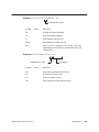
1
SIMATIC TIWAY 1 TI505 Network Interface Module User Manual Order Number: PPX:TIWAY–8124–2 Manual Assembly Number: 2587871–0053 Second Edition Copyright 1994 by Siemens Industrial Automation, Inc. All Rights Reserved — Printed in USA Reproduction, transmission or use of this document or contents is not permitted without express consent of Siemens Industrial Automation, Inc. All rights, including rights created by patent grant or registration of a utility model or design, are reserved. Since Siemens Industrial Automation, Inc. does not possess full access to data concerning all of the uses and applications of customer’s products, we do not assume responsibility either for customer product design or for any infringements of patents or rights of others which may result from our assistance. Technical data is subject to change. We check the contents of every manual for accuracy at the time it is approved for printing; however, there may be undetected errors. Any errors found will be corrected in subsequent editions. Any suggestions for improvement are welcomed. MANUAL PUBLICATION HISTORY TIWAY I TI505 Network Interface Module User Manual Order Manual Number: TIWAY–8124–2 Refer to this history in all correspondence and/or discussion about this manual. Event Date Description Original Issue Second Edition 8/88 3/94 Original Issue (2601210–0001) Second Edition (2601210–0002) LIST OF EFFECTIVE PAGES Pages Cover/Copyright History/Effective Pages iii — vii viii — ix 1-1 — 1-6 2-1 — 2-20 3-1 — 3-21 4-1 — 4-44 A-1 — A-3 B-1 — B-2 C-1 — C-2 D-1 — D-2 E-1 — E-2 Registration Description Second Second Second Second Second Second Second Second Second Second Second Second Second Second Pages Description Contents PREFACE CHAPTER 1 TIWAY I OVERVIEW 1.1 TIWAY I FEATURES . . . . . . . . . . . . . . . . . . . . . . . . . . . . . . . . . . . . . . . . . . . . . . . . . . . . . . . . . . . . 1-1 1.2 TIWAY I OPTIONS . . . . . . . . . . . . . . . . . . . . . . . . . . . . . . . . . . . . . . . . . . . . . . . . . . . . . . . . . . . . 1-2 1.3 SYSTEM BLOCK DIAGRAM . . . . . . . . . . . . . . . . . . . . . . . . . . . . . . . . . . . . . . . . . . . . . . . . . . . . 1-2 1.4 TIWAY I UNIVERSAL COMMAND LANGUAGE, UCL . . . . . . . . . . . . . . . . . . . . . . . . . . . . . . 1-3 1.5 THE TI505 NIM . . . . . . . . . . . . . . . . . . . . . . . . . . . . . . . . . . . . . . . . . . . . . . . . . . . . . . . . . . . . . . . 1-4 CHAPTER 2 NETWORK DESIGN CONSIDERATIONS 2.1 TIWAY I NETWORK CONFIGURATION . . . . . . . . . . . . . . . . . . . . . . . . . . . . . . . . . . . . . . . . . . . 2-1 2.1.1 Communication Media . . . . . . . . . . . . . . . . . . . . . . . . . . . . . . . . . . . . . . . . . . . . 2-2 2.1.2 Media Redundancy . . . . . . . . . . . . . . . . . . . . . . . . . . . . . . . . . . . . . . . . . . . . . . . 2-3 2.2 RS-232-C CABLE INSTALLATION . . . . . . . . . . . . . . . . . . . . . . . . . . . . . . . . . . . . . . . . . . . . . . . 2-4 2.2.1 RS-232-C Connections . . . . . . . . . . . . . . . . . . . . . . . . . . . . . . . . . . . . . . . . . . . . . 2-4 2.2.2 RS-232-C Timing Considerations . . . . . . . . . . . . . . . . . . . . . . . . . . . . . . . . . . . . . 2-5 2.3 LOCAL LINE CABLE INSTALLATION . . . . . . . . . . . . . . . . . . . . . . . . . . . . . . . . . . . . . . . . . . . . . 2-6 2.3.1 Local Line Characteristics . . . . . . . . . . . . . . . . . . . . . . . . . . . . . . . . . . . . . . . . . . 2-6 2.3.2 Local Line Cable . . . . . . . . . . . . . . . . . . . . . . . . . . . . . . . . . . . . . . . . . . . . . . . . . . 2-8 2.3.3 Local Line Tap Housings . . . . . . . . . . . . . . . . . . . . . . . . . . . . . . . . . . . . . . . . . . . 2-10 2.3.4 Planning Considerations . . . . . . . . . . . . . . . . . . . . . . . . . . . . . . . . . . . . . . . . . . 2-12 2.3.5 Local Line Tap Spacing . . . . . . . . . . . . . . . . . . . . . . . . . . . . . . . . . . . . . . . . . . . 2-12 2.3.6 Cable Routing . . . . . . . . . . . . . . . . . . . . . . . . . . . . . . . . . . . . . . . . . . . . . . . . . . . . 2-14 2.3.7 Obstructions . . . . . . . . . . . . . . . . . . . . . . . . . . . . . . . . . . . . . . . . . . . . . . . . . . . . . . 2-15 2.4 LOCAL LINE BIASING . . . . . . . . . . . . . . . . . . . . . . . . . . . . . . . . . . . . . . . . . . . . . . . . . . . . . . . 2-16 2.4.1 Biasing Configurations . . . . . . . . . . . . . . . . . . . . . . . . . . . . . . . . . . . . . . . . . . . . 2-16 2.4.2 Networks with only Self-biased Devices . . . . . . . . . . . . . . . . . . . . . . . . . . . . 2-17 2.4.3 Networks with a Single Switch-biased Device . . . . . . . . . . . . . . . . . . . . . . . 2-17 2.4.4 Networks with Two or More Switch-biased Devices . . . . . . . . . . . . . . . . . . 2-18 2.4.5 Terminating the Local Line . . . . . . . . . . . . . . . . . . . . . . . . . . . . . . . . . . . . . . . . 2-19 CHAPTER 3 INSTALLATION 3.1 GENERAL REQUIREMENTS . . . . . . . . . . . . . . . . . . . . . . . . . . . . . . . . . . . . . . . . . . . . . . . . . . . . 3-1 3.2 INSTALLING THE NIM . . . . . . . . . . . . . . . . . . . . . . . . . . . . . . . . . . . . . . . . . . . . . . . . . . . . . . . . . 3-4 3.3 SETTING THE DIPSWITCHES . . . . . . . . . . . . . . . . . . . . . . . . . . . . . . . . . . . . . . . . . . . . . . . . . . . . 3-5 TIWAY 1 TI505 NIM User Manual Contents iii 3.4 INSERTING THE MODULE INTO THE BASE . . . . . . . . . . . . . . . . . . . . . . . . . . . . . . . . . . . . . . 3-12 3.5 NIM SWITCHES . . . . . . . . . . . . . . . . . . . . . . . . . . . . . . . . . . . . . . . . . . . . . . . . . . . . . . . . . . . . . 3-14 3.6 TI505 NIM DIAGNOSTICS . . . . . . . . . . . . . . . . . . . . . . . . . . . . . . . . . . . . . . . . . . . . . . . . . . . . 3-16 3.7 MODULE LOGIN VERIFICATION . . . . . . . . . . . . . . . . . . . . . . . . . . . . . . . . . . . . . . . . . . . . . . 3-21 3.8 CONNECTING THE NETWORK CABLES . . . . . . . . . . . . . . . . . . . . . . . . . . . . . . . . . . . . . . . . 3-21 CHAPTER 4 NIM PRIMITIVES 4.1 OVERVIEW . . . . . . . . . . . . . . . . . . . . . . . . . . . . . . . . . . . . . . . . . . . . . . . . . . . . . . . . . . . . . . . . . . 4-1 4.2 PURPOSE . . . . . . . . . . . . . . . . . . . . . . . . . . . . . . . . . . . . . . . . . . . . . . . . . . . . . . . . . . . . . . . . . . . 4-2 4.3 STRUCTURE AND OPERATION . . . . . . . . . . . . . . . . . . . . . . . . . . . . . . . . . . . . . . . . . . . . . . . . . 4-2 4.3.1 Normal Operation and Exceptions . . . . . . . . . . . . . . . . . . . . . . . . . . . . . . . . . . 4-4 4.3.2 Exception When Reading . . . . . . . . . . . . . . . . . . . . . . . . . . . . . . . . . . . . . . . . . . 4-5 4.3.3 Exception When Writing . . . . . . . . . . . . . . . . . . . . . . . . . . . . . . . . . . . . . . . . . . . . 4-5 4.4 LOGICAL GROUPS . . . . . . . . . . . . . . . . . . . . . . . . . . . . . . . . . . . . . . . . . . . . . . . . . . . . . . . . . . . 4-6 4.5 FIELD DEFINITIONS . . . . . . . . . . . . . . . . . . . . . . . . . . . . . . . . . . . . . . . . . . . . . . . . . . . . . . . . . . . 4-8 4.5.1 Field Symbols . . . . . . . . . . . . . . . . . . . . . . . . . . . . . . . . . . . . . . . . . . . . . . . . . . . . . . 4-9 4.5.2 Length Field – LLLL . . . . . . . . . . . . . . . . . . . . . . . . . . . . . . . . . . . . . . . . . . . . . . . . . 4-9 4.5.3 Primitive Code Field – PP . . . . . . . . . . . . . . . . . . . . . . . . . . . . . . . . . . . . . . . . . . 4-10 4.5.4 Descriptor Field . . . . . . . . . . . . . . . . . . . . . . . . . . . . . . . . . . . . . . . . . . . . . . . . . . . 4-10 4.5.5 Basic Data Unit – DDDD . . . . . . . . . . . . . . . . . . . . . . . . . . . . . . . . . . . . . . . . . . . 4-11 4.6 DATA ELEMENT TYPES AND FORMATS . . . . . . . . . . . . . . . . . . . . . . . . . . . . . . . . . . . . . . . . . 4-12 4.7 DATA ELEMENT LOCATION RANGES . . . . . . . . . . . . . . . . . . . . . . . . . . . . . . . . . . . . . . . . . . 4-16 4.8 DATA FIELD LENGTH RESTRICTIONS . . . . . . . . . . . . . . . . . . . . . . . . . . . . . . . . . . . . . . . . . . . 4-17 4.9 TI505 NIM PRIMITIVE DESCRIPTIONS . . . . . . . . . . . . . . . . . . . . . . . . . . . . . . . . . . . . . . . . . . 4-19 4.9.1 Exception Primitive – Code 00 . . . . . . . . . . . . . . . . . . . . . . . . . . . . . . . . . . . . . 4-20 4.9.2 Native Primitive – Code 01 . . . . . . . . . . . . . . . . . . . . . . . . . . . . . . . . . . . . . . . . 4-22 4.9.3 Status Primitive – Code 02 . . . . . . . . . . . . . . . . . . . . . . . . . . . . . . . . . . . . . . . . . 4-23 4.9.4 Configuration Primitive – Code 03 . . . . . . . . . . . . . . . . . . . . . . . . . . . . . . . . . 4-24 4.9.5 Primitive Format Configuration – Code 04 . . . . . . . . . . . . . . . . . . . . . . . . . . 4-25 4.9.6 Packed Native Primitive – Code 05 . . . . . . . . . . . . . . . . . . . . . . . . . . . . . . . . 4-26 4.9.7 Change State Primitive – Code 10 . . . . . . . . . . . . . . . . . . . . . . . . . . . . . . . . . 4-27 4.9.8 Read Block Primitive – Code 20 . . . . . . . . . . . . . . . . . . . . . . . . . . . . . . . . . . . . 4-28 4.9.9 Read Random Block Primitive – Code 21 . . . . . . . . . . . . . . . . . . . . . . . . . . . 4-29 4.9.10 Write Block Primitive – Code 30 . . . . . . . . . . . . . . . . . . . . . . . . . . . . . . . . . . . . 4-30 4.9.11 Write Random Block Primitive – Code 31 . . . . . . . . . . . . . . . . . . . . . . . . . . . 4-31 4.9.12 Block Data Acquisition Primitive Codes 50 51 52 . . . . . . . . . . . . . . . . . . . . 4-32 4.9.13 Record Data Acquisition Primitive Codes 55 56 57 . . . . . . . . . . . . . . . . . . 4-36 4.9.14 Summary of Primitives . . . . . . . . . . . . . . . . . . . . . . . . . . . . . . . . . . . . . . . . . . . . . 4-41 iv Contents SIMATIC PCS 7 OSx Library Manual APPENDIX A PM550 CIM REQUIREMENTS . . . . . . . . . . . . . . . . . . . . . . . . . . . . . . . . . . A-1 A.1 INTRODUCTION . . . . . . . . . . . . . . . . . . . . . . . . . . . . . . . . . . . . . . . . . . . . . . . . . . . . . . . . . . . . . A-1 A.2 LOCAL LINE LENGTH . . . . . . . . . . . . . . . . . . . . . . . . . . . . . . . . . . . . . . . . . . . . . . . . . . . . . . . . . A-1 A.3 LOCAL LINE BIAS AND TERMINATION . . . . . . . . . . . . . . . . . . . . . . . . . . . . . . . . . . . . . . . . . . A-1 A.3.1 Networks with Switch-biased Devices and CIMs . . . . . . . . . . . . . . . . . . . . A-2 A.3.2 Networks with Only Self-biasing Devices and CIMs . . . . . . . . . . . . . . . . . . A-2 APPENDIX B NETWORK CONFIGURATION DATA SHEET . . . . . . . . . . . . . . . . . . . . . . . B-1 APPENDIX C NETWORK EVALUATION FORM . . . . . . . . . . . . . . . . . . . . . . . . . . . . . . . . C-1 APPENDIX D SPECIFICATIONS . . . . . . . . . . . . . . . . . . . . . . . . . . . . . . . . . . . . . . . . . . . . . D-1 APPENDIX E PRIMITIVE EXAMPLES . . . . . . . . . . . . . . . . . . . . . . . . . . . . . . . . . . . . . . . . . E-1 TIWAY 1 TI505 NIM User Manual Contents v List of Figures 1-1 1-2 TIWAY I System Block Diagram . . . . . . . . . . . . . . . . . . . . . . . . . . . . . . . . . . . . . . . . . . . . . . . . 1-3 NIM Simplified Block Diagram . . . . . . . . . . . . . . . . . . . . . . . . . . . . . . . . . . . . . . . . . . . . . . . . . 1-6 2-1 2-2 2-3 2-4 2-5 Number of Local Line Secondaries versus Cable Length . . . . . . . . . . . . . . . . . . . . . . . . 2-9 TIWAY I Tap Housing . . . . . . . . . . . . . . . . . . . . . . . . . . . . . . . . . . . . . . . . . . . . . . . . . . . . . . . . . 2-10 Tap Spacing Examples . . . . . . . . . . . . . . . . . . . . . . . . . . . . . . . . . . . . . . . . . . . . . . . . . . . . . . 2-13 Local Line with Two or More Switch-biased NIMs . . . . . . . . . . . . . . . . . . . . . . . . . . . . . . 2-18 Terminating the Local Line . . . . . . . . . . . . . . . . . . . . . . . . . . . . . . . . . . . . . . . . . . . . . . . . . . . 2-20 3-1 3-2 3-3 3-4 3-5 NIM Dipswitches . . . . . . . . . . . . . . . . . . . . . . . . . . . . . . . . . . . . . . . . . . . . . . . . . . . . . . . . . . . . . 3-5 Dipswitch Summary . . . . . . . . . . . . . . . . . . . . . . . . . . . . . . . . . . . . . . . . . . . . . . . . . . . . . . . . . . 3-6 Installing the NIM in the I/O Base . . . . . . . . . . . . . . . . . . . . . . . . . . . . . . . . . . . . . . . . . . . . . 3-13 NIM Switches . . . . . . . . . . . . . . . . . . . . . . . . . . . . . . . . . . . . . . . . . . . . . . . . . . . . . . . . . . . . . . . 3-14 NIM Status Indicators . . . . . . . . . . . . . . . . . . . . . . . . . . . . . . . . . . . . . . . . . . . . . . . . . . . . . . . . 3-16 4-1 4-2 4-3 4-4 4-5 4-6 4-7 4-8 Basic Primitive Structure . . . . . . . . . . . . . . . . . . . . . . . . . . . . . . . . . . . . . . . . . . . . . . . . . . . . . . 4-3 Binary Weight of the Fields . . . . . . . . . . . . . . . . . . . . . . . . . . . . . . . . . . . . . . . . . . . . . . . . . . . . 4-4 Primitive Request and Response Field Format . . . . . . . . . . . . . . . . . . . . . . . . . . . . . . . . . . 4-8 Discrete Data Element Format . . . . . . . . . . . . . . . . . . . . . . . . . . . . . . . . . . . . . . . . . . . . . . . 4-13 Packed Discrete Data Element Format . . . . . . . . . . . . . . . . . . . . . . . . . . . . . . . . . . . . . . . 4-13 Forced Word Data Element Format . . . . . . . . . . . . . . . . . . . . . . . . . . . . . . . . . . . . . . . . . . 4-14 Forced Discrete and CR Data Element Format . . . . . . . . . . . . . . . . . . . . . . . . . . . . . . . 4-15 Secondary System Status Data Element Format . . . . . . . . . . . . . . . . . . . . . . . . . . . . . . 4-15 A-1 Local Line Bias and Termination . . . . . . . . . . . . . . . . . . . . . . . . . . . . . . . . . . . . . . . . . . . . . . A-3 vi Contents SIMATIC PCS 7 OSx Library Manual List of Tables 2-1 2-2 RS-232-C Connections . . . . . . . . . . . . . . . . . . . . . . . . . . . . . . . . . . . . . . . . . . . . . . . . . . . . . . . 2-4 Pin Assignments for Local Line Connectors . . . . . . . . . . . . . . . . . . . . . . . . . . . . . . . . . . . . 2-7 3-1 3-2 3-3 TI505 Component Power Requirements . . . . . . . . . . . . . . . . . . . . . . . . . . . . . . . . . . . . . . . 3-2 Network Address Selection . . . . . . . . . . . . . . . . . . . . . . . . . . . . . . . . . . . . . . . . . . . . . . . . . . . 3-7 Network Data Rate Switch Settings . . . . . . . . . . . . . . . . . . . . . . . . . . . . . . . . . . . . . . . . . . . 3-8 4-1 4-2 4-3 4-4 4-5 4-6 4-7 4-8 4-9 Logical Primitive Assignment . . . . . . . . . . . . . . . . . . . . . . . . . . . . . . . . . . . . . . . . . . . . . . . . . . 4-6 TI505 NIM Primitive Subset . . . . . . . . . . . . . . . . . . . . . . . . . . . . . . . . . . . . . . . . . . . . . . . . . . . . 4-7 Summary of Primitive Field Symbols . . . . . . . . . . . . . . . . . . . . . . . . . . . . . . . . . . . . . . . . . . . 4-9 Data Element Types and Lengths . . . . . . . . . . . . . . . . . . . . . . . . . . . . . . . . . . . . . . . . . . . . 4-12 Data Element Location Ranges . . . . . . . . . . . . . . . . . . . . . . . . . . . . . . . . . . . . . . . . . . . . . . 4-16 Maximum Read Primitive Data Byte Length . . . . . . . . . . . . . . . . . . . . . . . . . . . . . . . . . . . 4-17 Maximum Write Primitive Data Byte Length . . . . . . . . . . . . . . . . . . . . . . . . . . . . . . . . . . . 4-18 Summary of Primitives . . . . . . . . . . . . . . . . . . . . . . . . . . . . . . . . . . . . . . . . . . . . . . . . . . . . . . . 4-41 Summary of Primitives(extended addressing) . . . . . . . . . . . . . . . . . . . . . . . . . . . . . . . . . 4-43 TIWAY 1 TI505 NIM User Manual Contents vii Preface MANUAL OVERVIEW This manual contains the information necessary to install and operate the SIMATIC TI505 Network Interface Module (NIM). The following information is provided. NIM specifications Installation and testing procedures Operating instructions and descriptions SIMATIC TIWAY I primitive descriptions and examples MANUAL ORGANIZATION This manual is organized as follows: CHAPTER 1 — TIWAY I OVERVIEW contains an overview of the TIWAY I network and an explanation of how the TI505 NIM operates within this network. CHAPTER 2 — NETWORK DESIGN CONSIDERATIONS describes possible network design configurations, and the use of modems with TIWAY I. Local Line cabling, biasing, and termination are also discussed. CHAPTER 3 — INSTALLATION describes NIM installation and diagnostic procedures. CHAPTER 4 — NIM PRIMITIVES describes NIM operation and the primitive subset supported by the NIM. APPENDIX A — SIMATIC PM550 CIM REQUIREMENTS contains procedures for Local Line biasing and termination for networks that contain a mixture of TI505 NIMs and PM550 Computer Interface Modules (CIM). APPENDIX B — NETWORK CONFIGURATION DATA SHEET contains a form that will help you plan your network. APPENDIX C — NETWORK EVALUATION FORM contains a TIWAY network evaluation form. You can submit the completed form to Siemens for a network evaluation. TIWAY 1 TI505 NIM User Manual Preface ix APPENDIX D — SPECIFICATIONS provides general specifications for the TI505 NIM APPENDIX E — PRIMITIVE EXAMPLES provides a simple primitive example in normal and extended addressing modes. RELATED PUBLICATIONS The following publications contain additional information on TIWAY I and TIWAY I compatible products. To order these publications, contact your Siemens Industrial Automation, Inc. distributor or sales office. If you need assistance in contacting your distributor or sales office in the United States, call 1–800–964–4114. Siemens Manual Number SIMATIC TIWAY I Host Adapter User Manual SIMATIC TIWAY I Host Software Programming Manual for DEC PDP–11 for TI and IBM Personal Computers for DEC VAX UNILINK PPX:TIWAY–8123 PM550 Network Interface Module User Manual SIMATIC 5TI Network Interface Module User Manual SIMATIC UNILINK Host Adapter User Manual SIMATIC TIWAY I TI500 NIM User Manual x Preface PPX:TIWAY–8102 PPX:TIWAY–8107 PPX:TIWAY–8108 PPX:550–8110 PPX:5TI–8105 PPX:TIWAY–8121 PPX:TIWAY–8110 TIWAY 1 TI505 NIM User Manual Chapter 1 TIWAY 1 Overview 1.1 TIWAY I FEATURES TIWAY I is an industrial Local Area Network (LAN) designed to satisfy today’s factory and plant requirements for data acquisition and control of manufacturing processes. It is a significant enhancement of the Siemens “Local Line,” which supports the PM550 Programmable Controllers (P/Cs) and DS 990 computer products. The TIWAY I network provides a reliable and flexible communication architecture. Two communication media options are available: RS-232-C/423 — provides modem interface for large geographic coverage. Local Line — provides high noise immunity for networks up to 25,000 feet (7620 meters). Throughout this manual, the following networking terms are used. HDLC — TIWAY I High-level Data Link Control data communications procedures with CRC–16 error-checking and message-length error-checking Primary — HDLC network manager (TIWAY I Host Adapter, TIWAY I Gateway, or UNILINK Host Adapter with the Network Manager function) Secondary — device operating as an HDLC secondary slave (NIMs, UNILINK Secondary Adapters, UNILINK Host Adapter acting as a Secondary) Attached device — P/C, robot, etc. (a P/C connected to the NIM, robot connected to a UNILINK Secondary Adapter) Host — computer or intelligent device establishing network communications. TIWAY 1 TI505 NIM User Manual TIWAY 1 Overview 1-1 1.1 TIWAY I OPTIONS TIWAY I network products provide a number of options. 1.2 TIWAY I networks can be configured for short distances or a long distances. Redundant or single media transmission is available. Baud rates from 110 baud to 115.2K baud are available. TIWAY I devices can operate with modems in either full or half duplex mode, synchronously or asynchronously. Both NRZ and NRZI data encoding are available. SYSTEM BLOCK DIAGRAM Figure 1Figure 1 illustrates the basic system block diagram of a TIWAY I Network. System components include: 1-2 Host System Interfaces (including Host Adapters, Gateways, and Network Control Modules) Siemens Programmable Controller Network Interface Modules (NIMs) UNILINK Secondary Adapters for interfacing non-Siemens products to the TIWAY I Network TIWAY 1 Overview TIWAY 1 TI505 NIM User Manual 1.3 TIWAY I UNIVERSAL COMMAND LANGUAGE, UCL TIWAY I provides a Universal Command Language for all communication on the network. The UCL consists of a set of high-level request/response transactions known as Primitives. Primitives are used for: Reading and writing data Acquiring status of devices attached to the network Performing control operations on attached devices The Host issues requests (Primitives) to the NIMs and Secondary Adapters. The secondaries then perform the requested operations on the attached devices and return the appropriate response to the Host to complete the transaction. See Figure 1. Host Systems Host System Interfaces Command Initiators Network Media Secondary Adapters Siemens Programmable Controllers Non–Siemens devices Responders Figure 1 TIWAY I System Block Diagram TIWAY 1 TI505 NIM User Manual TIWAY 1 Overview 1-3 1.4 THE TI505 NIM The TI505 NIM is the TIWAY I Network Interface Module for the SIMATIC TI505 Programmable Controllers. See Chapter 3 for a specific listing of controllers supported by the TI505 NIM. The TI505 NIM provides several features which ensure maximum network signal integrity. 1-4 Each communication port is provided with a “Jabberstop” circuit to disable the port’s transmitter in the event of a communication port failure. This helps minimize failures resulting in continuous network transmission which would dominate the communication channel. The NIM provides data integrity checking of network communications. The NIM meets several stringent noise and environmental specifications. Built-in diagnostics aid in troubleshooting NIM failures and problems. Chapter 3 provides a description of the diagnostics. TIWAY 1 Overview TIWAY 1 TI505 NIM User Manual The TI505 NIM provides redundant TIWAY I communication ports. Each of the following models supports a specific type of network communication media. PPX: Number Port A Port B PPX:505-7339 PPX:505-7340 Local Line RSĆ232ĆC/423 Local Line RSĆ232ĆC/423 The RS-232-C/423 media interface is configured as Data Terminal Equipment (DTE) and is used to connect the NIM to Data Communication Equipment (DCE) for operation with modems. This interface uses RS-423 drivers and receivers and operates at RS-423-A signal levels (+5 or –5 volts). These levels are also RS-232-C compatible. The pin assignments for the RS-232-C port are given in Chapter 2. The Local Line interface is a differential line port for use with shielded twisted pair cable. The Local Line interface provides line isolation and high noise immunity for installations up to 10,000 feet (25,000 feet depending on system loading and baud rate selection). The Local Line interface is recommended for applications where electrical noise may be a problem. Redundancy is supported for either choice of media. TIWAY 1 TI505 NIM User Manual TIWAY 1 Overview 1-5 Figure 2 is a simplified block diagram of the TI505 NIM. The media interface blocks are intentionally left unlabeled because the type of media interface depends on which NIM model you are using. The blocks are described as follows. Special Function Interface Controller (SFIC) — delivers and receives P/C communications. NIM controller — translates the communication (between Primitives and the P/C communication language). Communications controller — supervises data transactions between the NIM and the network host. NETWORK INTERFACE MODULE POWER SPECIAL FUNCTION INTERFACE CONTROLLER NIM CONTROLLER COMM. CONTROLLER MEDIA CIRCUITRY TO NETWORK COMM. MEDIA Figure 2 NIM Simplified Block Diagram The basic difference in the NIM models is the configuration of the media circuitry. 1-6 TIWAY 1 Overview TIWAY 1 TI505 NIM User Manual Chapter 2 Network Design Considerations 2.1 TIWAY I NETWORK CONFIGURATION TIWAY I is a multi-drop communication network which consists of a main trunk cable (the “spine”) and dropline cables. The network can connect up to 254 secondaries (e.g., TI505 P/Cs) to a host computer. The TI505 NIM provides the interface to the network host, enabling the host and the P/C to communicate with each other. Also included with this manual is a “TIWAY I Network Configuration Data Sheet” (Appendix B). This will assist you in maintaining a complete, up-to-date record of the configuration of your network, which is especially important if you are using several different types of secondaries. TIWAY 1 Ti505 NIM User Manual Network Design Considerations 2-1 2.1.1 Communication Media The following signal-transmission media are supported by TIWAY I: RS-232-C/423 dedicated lease-line modem interface in which no dial-up is necessary, providing extended (cross-continental) geographic coverage. RF or short-haul modem link-ups (cross-plant or cross-town coverage). Siemens Local Line (up to 25,000 feet). NOTE TIWAY I does not directly support dial-up modems which require Modem Control Commands for communication switchover. This can be done, but specific equipment is required to dial the remote number from the host device. You can select from either type of media for the network, but you cannot mix the types of media. 2-2 Network Design Considerations TIWAY 1 TI505 NIM User Manual The selection of the network communication media depends primarily on the geographic distance to be spanned. The main TIWAY I trunk can be up to 10,000 feet long (25,000 feet depending on system loading and baud rate selection), and can have up to 254 droplines. Each dropline can be up to 100 feet long. For distances exceeding 25,000 feet, RS-232-C/423 media interfaces and modems should be used. NOTE The proper installation of your communication media requires careful planning and design. If you need assistance, a site survey is available from Siemens Industrial Automation, Inc. Simply fill out and return the enclosed “TIWAY I Network Evaluation Form”, (Appendix C). 2.1.2 Media Redundancy Media redundancy is supported for RS-232-C and Local Line NIMs. This means you can have backup communication media, in case of unforeseen cable problems or accidents. In order to achieve true redundancy, you must have completely redundant network media (network trunk lines, tap housings, drop lines, and modems). For example, if you need Local Line cable redundancy, you will need one PPX:505–7339 TI505 NIM, two separate twisted pair trunk (spine) cables, and a T-Tap and dropline for each port on the NIM. The primary reason for using media redundancy is to permit communications on an alternate channel when the main channel fails. The redundant media connection does not allow two independent networks to communicate with the same NIM. The NIM will respond over the same channel that received the network command. For example, if the Host sends the command to Port A, the NIM will respond through Port A. TIWAY 1 Ti505 NIM User Manual Network Design Considerations 2-3 2.2 RS-232-C CABLE INSTALLATION The physical layer in TIWAY I provides a modem interface for synchronous or asynchronous modems at data transmission rates up to 115.2K bits per second. 2.2.1 RS-232-C Connections The modem interface provides standard signals, as defined in Table 2Table 3 for control of two-way alternate data transmission using both half and full duplex modems.The modem interface is a standard “Type E” DTE configuration as defined in Section 5 of EIA RS-232-C. This interface uses a male (plug) 25-pin D-type connector on the communication cable. The circuits and pin assignments for the RS-232-C connector are shown in Table 3. Table 3 RS-232-C Connections 2-4 Pin ISO# RS-232-C Name – Function 1 2 3 4 5 6 7 8 101 103 104 105 106 107 102 109 15 17 20 114 115 108/2 AA – Protective Ground (chassis) BA – Transmitted Data BB – Received Data CA – Request to Send (RTS) CB – Clear to Send (CTS) CC – Data Set Ready (DSR) AB – Signal Ground CF – Received Line Signal Detector/ Data Carrier Detect (RLSD/DCD) DB – Transmitter Signal Element Timing DD – Receiver Signal Element Timing CD – Data Terminal Ready (DTR) Network Design Considerations TIWAY 1 TI505 NIM User Manual 2.2.2 RS-232-C Timing Considerations If you use the TI505 NIM with a dedicated short-haul RF modem, the NIM has a one-second time-out between the transmission of its RS-232-C Request to Send (RTS) and the RS-232-C Clear to Send (CTS) response. This time-out value is set at one second to enable the RF device to switch from receive to transmit without losing access to the transmission media. NOTE This extended time-out feature is an important consideration when selecting a TIWAY I-compatible RF Modem. Transmitter/Receiver turnaround time must be less than the one second network time-out. An additional half-second delay from Clear to Send (CTS) to start of transmission can be added by setting the Keydelay Switch to the open position. (Chapter 3 provides additional information concerning dipswitch settings.) This may be required to allow the transmitter to reach full power before start of transmission. There is also a one-second wait period for DCD to turn off in a half duplex modem. TIWAY 1 Ti505 NIM User Manual Network Design Considerations 2-5 2.3 LOCAL LINE CABLE INSTALLATION The following paragraphs describe Local Line characteristics and installation guidelines. 2.3.1 Local Line Characteristics The TIWAY I Local Line is a physical signaling technique (baseband, differential current drive) which operates over shielded, twisted-pair cabling. The Local Line cable may be up to 25,000 feet long, depending on loading and baud rate selection. It uses tap housings to simplify the addition of network connections. The Local Line is designed to operate with shielded, twisted-pair cable which has a characteristic impedance of 124 ohms. Taps and 9-pin connectors are supplied with the Local Line, but extras may be necessary for cable splicing. Suggested cable routing procedures are provided later in this chapter. 2-6 Network Design Considerations TIWAY 1 TI505 NIM User Manual The interface cable should have a male, 9-pin D-type receptacle with pin assignments as shown in Table 4. Table 4 Pin Assignments for Local Line Connectors Pin 1 2 3 4 5 6 7 8 9 Name Shield LLM+ LLM– TIWAY 1 Ti505 NIM User Manual Description No connection No connection Cable shield and signal common No connection No connection Positive biased signal line No connection No connection Negative biased signal line Network Design Considerations 2-7 2.3.2 Local Line Cable The TIWAY I local line network cable consists of a main cable or spine with droplines or taps for each Secondary. Interrelated network variables having direct influence on network performance are: Maximum trunk cable length Cable type Tap length Tap spacing Number of secondaries Maximum baud rates Siemens recommends Belden 9860 twisted pair cabling, or its equivalent, for use as the Local Line network spine. Belden 9271, or its equivalent, should be used for the dropline. Brands other than those listed here will be specified by Siemens on request. CAUTION All local and national electrical codes and fire codes should be observed when installing wiring. 2-8 Network Design Considerations TIWAY 1 TI505 NIM User Manual Figure 1 illustrates the relationship of cable distance to the number of secondaries for different baud rates for two types of twisted pair cable. Note that the cable distance (in thousands of feet) is shown vertically; the maximum number of units that may be attached is shown horizontally. Figure 1 Number of Local Line Secondaries versus Cable Length As shown in Figure 2Figure 1, when you use Belden 9860 cable (or its equivalent), up to 75 stations can be attached to a network operating at 38K bps and having a spine length of 20,000 feet. At 115.2K bps, the maximum length of a Local Line network having 254 stations is 10,000 feet. TIWAY 1 Ti505 NIM User Manual Network Design Considerations 2-9 2.3.3 Local Line Tap Housings The tap housing, shown in Figure 2, is made by Siemens specifically for its Local Line network. The tap housing can be mounted rigidly to a NEMA panel or other enclosure. It can also be used to splice cables in a cable tray without being rigidly mounted. The tap housing not only allows an orderly connection to the TIWAY I network, but also contains terminating resistors, resists moisture, relieves strain, and provides noise isolation for attached cabling. Tap housings are included for each Local Line port; however, extras may be ordered from your Applications Engineering Distributor or from Siemens. Order PPX:500–5606. Figure 2 TIWAY I Tap Housing 2-10 Network Design Considerations TIWAY 1 TI505 NIM User Manual With the cover removed from the PPX:500–5606 Tap Housing, note that there are three sets of terminals, and that each set is labeled G (Ground), W (White), and B (Blue). (See Figure 2Figure 2.) One set of these terminals is for the incoming Local Line twisted pair; the center set is for the drop line; and the remaining set is used to connect the Local Line to the following node, or to terminate the Local Line if the tap housing is the last one on the network trunk. For consistency in installation, always connect the LLM+ (Pin 6 of the Local Line Connector) to the white strand of the twisted pair and to the terminal marked “W” in the tap housing. Connect the blue strand to the LLM– (Pin 9 of the Local Line Connector) and to the terminal marked “B” in the tap housing. The Cable Shield and Signal Common should be connected to Pin 3 of the Local Line connector and to terminal “G” inside the tap housing. NOTE All Siemens tap housings contain factory-installed termination resistors. If the tap housing is not used to terminate the Local Line, the terminating resistors must be removed when the output cable is attached. TIWAY 1 Ti505 NIM User Manual Network Design Considerations 2-11 2.3.4 Planning Considerations Some major points to consider during the planning phase of a Local Line network are as follows: 2.3.5 From the start, allow for system growth. This means making provisions for the attachment of additional computing devices by routing cables through all probable areas of future plant expansion. Always make the network flexible enough to allow for re-arrangement of plant equipment. Since network system noise is usually picked up by the interconnecting wiring, try to avoid routing the communization wiring near noise sources such as large motor starters, high current switches, and transformers. If cable redundancy is desired, the two cables should never be routed along the same path, since the environmental or other factors which disable one cable will very likely disable the second. A detailed record of design and routing should be created and maintained. This record should be complete enough to enable a user to trace and physically locate all cable paths and hardware components. Local Line Tap Spacing To calculate the minimum distance between tap nodes, use the length of the dropline at the last tap node. A tap node consists of either a single tap on the TIWAY I trunk cable or a pair of taps separated by less than the minimum tap node separation distance. The minimum distance between a given tap node and the next tap node on the network is equal to one-half the length of the longer drop line at the given node. No limit is placed on the number of NIMs that can be daisy-chained to form a drop line off the main trunk as long as the resulting drop length is no greater than 100 feet. Figure 3 illustrates three typical examples of tap spacing. 2-12 Network Design Considerations TIWAY 1 TI505 NIM User Manual Figure 3 Tap Spacing Examples TIWAY 1 Ti505 NIM User Manual Network Design Considerations 2-13 2.3.6 Cable Routing Cable routing should be planned as if the path between all stations on the network were free of obstructions. Next, modify the first routing to account for obstructions, then calculate the amount of cable needed. CAUTION All local and national electrical codes and fire codes should be observed when installing wiring. In general, there are three types of network cabling routes: Under-floor In-ceiling Surface ducting Any choice of these three routes may be used on a single network. The choice is often determined by whether the building (or buildings) in which the network is being installed is new construction, or is an existing building. The following paragraphs describe some of the advantages and disadvantages of each type of cable routing. 2.3.6.1 Under-floor Routing For under-floor routing, the cable can be enclosed within ducts or, with raised flooring, in the “open air.” Under-floor systems enclosed in ducts are usually expensive, and while they are better-protected against unauthorized taps than are “open air” systems, they often make future expansion of the network more difficult and expensive. “Open air” under-floor cabling systems usually provide good access and allow maximum network expansion and flexibility. 2.3.6.2 In-ceiling Routing For in-ceiling routing, network cables are usually supported in troughs or with hooks and clamps every 10 or 15 feet. In-ceiling installations provide flexibility, usually cost less, and provide easy access. 2-14 Network Design Considerations TIWAY 1 TI505 NIM User Manual In-ceiling cable networks are not always practical. In-ceiling installations can be difficult and sometimes dangerous in areas without drop ceilings (or that have unusually high ceilings). Also, closed ceiling systems usually trap dust and other debris, which makes cable maintenance difficult. 2.3.6.3 Surface Duct Routing Surface ducting for network cabling is usually installed along the baseboards or is attached to walls at desktop height. While surface ducting protects cables from both physical and EMI effects, it may also require that network computing devices be positioned near a wall. 2.3.7 Obstructions Aside from physical obstructions such as posts, walls, and partitions, electrical interference should also be avoided. In general, network cabling should never come into direct contact with any electrical conductor, and if cabling is installed inside a conduit, the conduit should be grounded in accordance with applicable electrical codes. Keep at least three feet between all network cabling and the following: Power lines carrying 440 volts or greater Generators Electric motors Transformers Electric welders Induction furnaces and heaters Rectifiers All sources of microwave radiation Fluorescent lighting Teletypes TIWAY 1 Ti505 NIM User Manual Network Design Considerations 2-15 2.4 LOCAL LINE BIASING In certain network configurations, the Local Line must be biased to raise its noise immunity and to prevent oscillations of receivers connected to the line. The need to apply a bias voltage to the Local Line depends on the interface configuration of your network. 2.4.1 Biasing Configurations It is very likely that you will have a mixture of TI505, SIMATIC TI500, and PM550 P/Cs on your network. Three different Local Line media biasing combinations exist, based on the number and type of interface devices used with the P/Cs. Possible combinations are Installations consisting solely of self-biased devices. Installations consisting of both switch-biased and self-biased devices. (Some older TIWAY I devices have Bias Switches.) Installations with PM550 CIMs. This section covers self-biased and switch-biased configurations only. (All TI505 NIMs are self-biasing.) Appendix A discusses biasing and terminating a Local Line having all three types of devices. CAUTION If a switch-biased Local Line interface port is unused (i.e., in a case where no redundant Local Line is installed) the Bias Switch on the unused port must be turned ON to prevent the entry of spurious noise into the NIM. 2-16 Network Design Considerations TIWAY 1 TI505 NIM User Manual 2.4.2 Networks with only Self-biased Devices This configuration exists when all TIWAY I Devices on the network are self-biasing (i.e., they do not have a Bias Switch.) In this case, the position on the line of the interface devices does not matter. 2.4.3 Networks with a Single Switch-biased Device This configuration exists when only one TIWAY I Device on the Local Line has the Bias Switch, and all other devices are self-biasing. The position of the switch-biased device on the line does not matter, but its Bias Switch must be on. TIWAY 1 Ti505 NIM User Manual Network Design Considerations 2-17 2.4.4 Networks with Two or More Switch-biased Devices This configuration exists when multiple switch-biased TIWAY I Devices are attached to the network, and they should be positioned as described in the following paragraphs. If two or more devices having the Bias Switch are attached, place one at each end of the Local Line, and turn on each Bias Switch. All other devices having a Bias Switch can then be placed anywhere on the network, with the Bias Switches turned off for the port being used. See Figure 4. LOCAL LINE END OF LOCAL LINE END OF LOCAL LINE BIAS SWITCH OFF ON ALL OTHER SECONDARY DEVICES SWITCH–BIASED NIM SWITCH–BIASED NIM BIAS SWITCH ON BIAS SWITCH ON Figure 4 Local Line with Two or More Switch-biased NIMs 2-18 Network Design Considerations TIWAY 1 TI505 NIM User Manual 2.4.5 Terminating the Local Line The TIWAY I Local Line is designed to operate with shielded, twisted-pair cable which has a characteristic impedance of 124 ohms. In all configurations, the Local Line must be properly terminated at both ends of the trunk to prevent an impedance mismatch which could result in signal reflections on the line. Termination is required regardless of the number or type of devices attached to the network. NOTE In the special case of a PM550 using a CIM as its interface to the network, see Appendix A for detailed line biasing and termination instructions, which vary from those listed here. Termination of the Local Line must be at the tap housings at the extreme ends of the network spine, and is accomplished as follows: 1. The factory-installed termination resistors in the tap housing (see Figure 5) are left in place in the tap housing which is to be used to terminate the Local Line. 2. If the termination resistors are used and the attached TIWAY I device has a Bias Switch, the Bias Switch should be set to the ON position. TIWAY 1 Ti505 NIM User Manual Network Design Considerations 2-19 NETWORK CABLE INPUT OUTPUT G G B W W G B TERMINATION RESISTORS 68 ohms 5% 1/4 WATT W B CABLE TO MODULE Figure 5 Terminating the Local Line NOTE All Siemens tap housings contain factory-installed terminating resistors. If the tap housing is not used to terminate the Local Line, the terminating resistors must be removed when the output cable is attached. 2-20 Network Design Considerations TIWAY 1 TI505 NIM User Manual Chapter 3 Installation 3.1 GENERAL REQUIREMENTS The following requirements must be met in order to install and use a TI505 NIM: 1. The appropriate NIM should be selected. PPX:505–7339 (Redundant Local Line) PPX:505–7340 (Redundant RS-232-C) 2. The TI505 NIM must be used with a model SIMATIC TI525 or SIMATIC TI535 P/C. For full NIM capabilities, the P/C software release level should be greater than (or equal to) the following releases. TI525 TI535 Release 2.2 Release 1.0 If you cannot determine whether your P/C release is compatible with the TI505 NIM, contact your Siemens Industrial Automation, Inc. distributor or sales office for assistance. If you need assistance in contacting your distributor or sales office in the United States, call 1–800–964–4114. 3. The communication configurations of all devices attached to the network must match; i.e., they should each have the same data rate, encoding, etc. 4. Calculate the I/O base power budget to make sure that there is enough power to operate all the modules installed in the base. Table 1 provides the power requirements for all currently available TI505 I/O modules. NOTE If you are not going to install your NIM immediately, store it in an antistatic bag until you are ready for installation. TIWAY 1 Ti505 NIM User Manual Installation 3-1 Table 1 TI505 Component Power Requirements Power Available (in watts) +5 V –5 V PPX:505–6660 Power Supply PPX: Number 3-2 Installation 55 Description 3.75 DC Power Required (in watts) +5 V –5 V PPX:505–6830 IOCC 5.0 0.1 PPX:505–6840 Distributed Base Controller 5.0 0.1 PPX:505–4008 24 VAC Input (8 point) 2.0 — PPX:505–4016 24 VAC Input (16 point) 2.0 — PPX:505–4032 24 VAC Input (32 point) 2.0 — PPX:505–4108 LVDC/TTL Input (8 point) 2.0 — PPX:505–4116 LVDC/TTL Input (16 point) 2.0 — PPX:505–4132 LVDC/TTL Input (32 point) 2.0 — PPX:505–4208 110 VAC Input (8 point) 2.0 — PPX:505–4216 110 VAC Input (16 point) 2.0 — PPX:505–4232 110 VAC Input (32 point) 2.0 — PPX:505–4308 24 VDC Input (8 point) 2.0 — PPX:505–4316 24 VDC Input (16 point) 2.0 — PPX:505–4332 24 VDC Input (32 point) 2.0 — PPX:505–4408 220 VAC Input (8 point) 2.0 — PPX:505–4416 220 VAC Input (16 point) 2.0 — PPX:505–4432 220 VAC Input (32 point) 2.0 — TIWAY 1 TI505 NIM User Manual Table 1 TI505 Component Power Requirements (Continued) PPX: Number Description DC Power Required (in watts) +5 V –5 V PPX:505–4508 24 VDC Output (8 point) 2.5 — PPX:505–4516 24 VDC Output (16 point) 2.5 — PPX:505–4532 24 VDC Output (32 point) 2.5 — PPX:505–4608 110 VAC Output (8 point) 2.5 — PPX:505–4616 110 VAC Output (16 point) 2.5 — PPX:505–4632 110 VAC Output (32 point) 2.5 — PPX:505–4708 24 VDC Output (8 point) 5.0 — PPX:505–4716 24 VDC Output (16 point) 5.0 — PPX:505–4732 24 VDC Output (32 point) 5.0 — PPX:505–4808 220 VAC Output (8 point) 5.0 — PPX:505–4816 220 VAC Output (16 point) 5.0 — PPX:505–4832 220 VAC Output (32 point) 5.0 — PPX:505–4908 Relay Output Form C (8 point) 2.5 — PPX:505–4916 Relay Output Form A (16 point) 2.5 — PPX:505–4932 Relay Output Form A (32 point) 2.5 — PPX:505–6010 Input Simulator 2.0 — PPX:505–6011 Output Simulator 2.5 — PPX:505–6108 Analog Input 4.0 — PPX:505–6202 Analog Output (2 point) 2.5 — PPX:505–6204 Analog Output (4 point) 5.0 — PPX:505–6208 Analog Output (8 point) 5.0 — PPX:505–6308 Word Input 4.0 — PPX:505–6408 Word Output 5.0 — PPX:505–7339 Local Line Network Interface 8.0 — PPX:505–7340 RS-232–C Network Interface 8.0 0.250 TIWAY 1 Ti505 NIM User Manual Installation 3-3 3.2 INSTALLING THE NIM To place a NIM into your TI505 system, you have to select the NIM communication parameters, install the NIM in the TI505 I/O base, connect the communication cables to the NIM, and initialize the system for operation. The Programmable Controller (P/C) and the programming device should be in place before you install a NIM. WARNING Do not insert or remove the NIM while power is applied to the P/C system, since doing this may cause personal injury, alter P/C memory, cause a P/C fatal error, or damage the module. The following steps summarize the NIM installation. 1. Disconnect power to the P/C system (I/O base, power supply, etc.). 2. Set the configuration dipswitches and LOCAL/REMOTE switch. 3. Insert the module into the base and secure it with the bezel screws. 4. Power up the P/C system. 5. Use the NIM diagnostics and LED status indicators to be sure the module is operating correctly. 6. Use a programming device to verify that the NIM is logged into the P/C. 7. Connect the network cables to the NIM. The following paragraphs provide detailed information for each step. 3-4 Installation TIWAY 1 TI505 NIM User Manual 3.3 SETTING THE DIPSWITCHES As Figure 1 illustrates, there are two blocks of dipswitches on the TI505 NIM. The block of eight switches is the NIM Network Address Selection switch. The block of ten switches is the Network Configuration Parameters switch. Note that the switches are numbered from left to right (when the switches are facing you). When setting up your NIM, use the configuration data sheet in Appendix B of this manual to record important configuration information. NOTE The configuration and address switch settings are read only once following a power-up or reset. Be sure to reset the NIM following any change in dipswitch settings or P/C memory reconfiguration. Network Address Selection Network Configuration Parameters Figure 1 NIM Dipswitches TIWAY 1 Ti505 NIM User Manual Installation 3-5 Figure 2 provides a summary of the dipswitch settings. The following paragraphs provide detailed information about the parameters selected by each switch. Network Configuration Parameters 0, CLOSED, ON 1, OPEN, OFF Transmit delay inactive Transmit delay active Lockout disabled Lockout enabled NRZ encoding NRZI encoding HDLC protocol X.25 protocol Half duplex Full duplex Synchronus Communication Asynchronous Data Transmission Rate See Table 3-3 Push down to select Position Selected Network Address Selection ON, CLOSED Position not Selected OFF, OPEN 1 2 4 0 8 16 32 64 128 Figure 2 Dipswitch Summary 3-6 Installation TIWAY 1 TI505 NIM User Manual 3.3.1 Selecting the Network Address Each TIWAY I Network Secondary must have a unique binary network address. The range of valid addresses is 1 to 254 (0000 0001 to 1111 1110 on switches 1–8 of the Network Address Selection dipswitch). Selecting addresses 0 or 255 (0000 0000 or 1111 1111) on the Network Address Selection dipswitch will cause the NIM to initialize in a test mode, and the NIM will fail to operate properly. See Table 2A for address values (bit weight) of each switch and Table 2B for addressing examples. Table 2 Network Address Selection Table 3–2A Bit Weight LSB MSB 3.3.2 Table 3–2B Address Examples 1 25 203 SW8 Open Open Open 0 SW7 Closed Closed Open 4 0 SW6 Closed Closed Closed SW5 8 0 SW5 Closed Open Open SW4 16 0 SW4 Closed Open Closed SW3 32 0 SW3 Closed Closed Closed SW2 64 0 SW2 Closed Closed Open SW1 128 0 SW1 Closed Closed Open Open Closed SW8 1 0 SW7 2 SW6 Selecting Network Configuration Parameters The Network Configuration Parameters dipswitch is used to select the parameters that define the network communication environment. Several switches on the Network Configuration Parameters dipswitch are ignored during Local Line operation. These switches are noted in the following descriptions. TIWAY 1 Ti505 NIM User Manual Installation 3-7 3.3.2.1 Data Transmission Rate Network Configuration Parameter switches 1 through 4 select the data transmission rate. All devices on the network must be configured to communicate at the same data rate. The data rates corresponding to the switch settings are shown in Table 3. For synchronous operation in RS-232-C communication, the rate of data transmission is established by the modem. When setting switches one through four, select a data rate which matches that of the modem exactly. If this is not possible, select the next lower data rate below that of the modems. (See the paragraph on Synchronous/Asynchronous Selection.) Table 3 Network Data Rate Switch Settings SWITCH SETTINGS SW1 SW2 SW3 0 0 0 0 0 0 0 0 1 1 1 1 1 1 1 1 0 0 0 0 1 1 1 1 0 0 0 0 1 1 1 1 0 0 1 1 0 0 1 1 0 0 1 1 0 0 1 1 DATA RATE (BPS) SW4 0 1 0 1 0 1 0 1 0 1 0 1 0 1 0 1 110 110 110 110 110 150 300 600 1200 2400 4800 9600 19,200 38,400 57,600 115,200 0 – closed = on 1 – open = off 3-8 Installation TIWAY 1 TI505 NIM User Manual 3.3.2.2 Synchronous / Asynchronous Selection Network Configuration Parameter switch 5 selects synchronous or asynchronous operation for modems. For synchronous modem communication, the NIM receives the transmit and receive timing signals from the modem via transmit signal timing element (DB), and receive signal timing element (DD). If the modem data rate does not match the TIWAY data rate exactly, the data rate select switches should be set to a rate that is the next lower data rate from the modem. For example, if a 56,000 bps synchronous modem is used, a data rate of 38,400 bps should be selected on the NIM. To select synchronous operation, set the switch to the open position (towards the bottom of the dipswitch). For asynchronous operation, the transmit and receive timing elements are generated within the NIM. Synchronous operation is not valid for Local Line operation. When you use the Local Line medium, this switch must be in the asynchronous position (towards the top of the dipswitch, closed, indicates asynchronous; towards the bottom of the dipswitch, open, is synchronous). 3.3.2.3 Full / Half Duplex Network Configuration Parameter switch 6 selects full or half duplex operation when communicating over an RS-232-C data link. When half duplex is selected (switch 6 is, closed, towards the top of the dipswitch) the NIM waits for the Data Carrier Detect (DCD) control signal from the modem to go inactive before activating the Request To Send (RTS) control signal. If full duplex operation is selected, the timing relationship between DCD and RTS will be ignored. When the Local Line communication media is used, this switch is ignored since no externally supplied communication control signals are supplied. TIWAY 1 Ti505 NIM User Manual Installation 3-9 3.3.2.4 X.25 / HDLC Network Configuration Parameter switch 7 selects the communication protocol. The HDLC protocol is activated when the switch is closed, or positioned towards the top of the dipswitch. The X.25 protocol is only activated when this switch is set open, or positioned towards the bottom of the dipswitch. The X.25 protocol is not used with the TIWAY I or UNILINK Host Adapter, although it is an option when communicating with any Primary supporting this protocol. 3.3.2.5 NRZ / NRZI Network Configuration Parameter switch 8 selects the method of data encoding used on the physical communication medium. The NRZI method of data encoding provides a mechanism for the proper decoding of received data in an asynchronous communication environment. In fact, NRZ encoding will not work satisfactorily except in the case of synchronous RS-232-C communication. When using Local Line, or asynchronous RS-232-C, NRZI encoding must be used. Either type of encoding may be used with synchronous RS-232-C communication. To select NRZI encoding, the switch should be open, or positioned towards the top of the dipswitch. To select NRZ encoding, the switch should be closed, or positioned towards the bottom of the dipswitch. 3-10 Installation TIWAY 1 TI505 NIM User Manual 3.3.2.6 Lockout / Enable Network Configuration Parameter switch 9 enables the P/C to “lockout” the NIM during time-critical operations. This function is not needed normally. During lockout, the NIM will not communicate with the P/C. The actual mechanism is as follows: 1. The P/C “sees” the NIM as an 8 channel discrete output module on the I/O portion of the scan. 2. If the P/C is to “lockout” the NIM during a time critical scan, it can set the image register address that corresponds to the 8th output of the module. If switch 9 of the NIM is open (positioned towards the bottom of the dipswitch) the NIM will not communicate with the P/C as long as the 8th output is set. The TI505 P/Cs allow you to configure the specific I/O addresses. You have to configure the I/O before you can determine the lockout bit address. See your P/C manual for details on I/O configuration. 3. In your Relay Ladder Logic (RLL) program, re-enable NIM to P/C communication by turning the output off after the P/C is able to resume communication with the NIM. 3.3.2.7 Transmit Delay or Keydelay Network Configuration Parameter switch 10 provides a delay of 500 milliseconds (following the receipt of Clear to Send (CTS) from a modem) before any data is transmitted. This delay may be required in radio modem installations to permit the transmitter to reach full power before transmitting data. This delay is activated when the key delay switch is set open (positioned towards the bottom of the dipswitch). This switch setting is ignored for Local Line operation. If you are using a radio modem that requires time to reach full power and you do not set this switch to provide the delay, erratic operation may occur. TIWAY 1 Ti505 NIM User Manual Installation 3-11 3.4 INSERTING THE MODULE INTO THE BASE It is advisable to install the NIM in the slot adjacent to the CPU (Central Processing Unit). This provides the following advantages. Easier access to switches and connectors Better LED indicator visibility Reduced electrical noise susceptibility To avoid causing electrostatic damage to the Printed Circuit Board (PCB) components, do not touch the PCB while inserting the module into the base. WARNING To minimize the risk of personal injury or equipment damage, always disconnect all system power before removing or installing I/O modules. Complete the following steps to install the module. 1. Disconnect power to the P/C system. 2. Position the module so that the front bezel is facing you. (See Figure 3.) 3. Hold the top and bottom of the bezel and carefully slide the module into the slot; pushing it all the way into the base. If you have inserted the module correctly, you will feel a slight increase in resistance as the module connects to the base plane connector. 4. Use a flat-head screwdriver to tighten the screws at the top and bottom of the bezel. The bezel screws ground the module to the base. Do not overtighten the screws. 5. Power-up the P/C system. 3-12 Installation TIWAY 1 TI505 NIM User Manual Figure 3 Installing the NIM in the I/O Base TIWAY 1 Ti505 NIM User Manual Installation 3-13 3.5 NIM SWITCHES There are three switches located under the hinged switch cover. These switches, which are shown in Figure 3Figure 4, are labeled RESET, TEST and LOCAL/REMOTE. Figure 3Figure 4 NIM Switches 3-14 Installation TIWAY 1 TI505 NIM User Manual 3.5.1 Reset This switch is a momentary contact switch which resets the NIM and initiates the power-up diagnostics. This switch causes all indicators to be on for approximately 1 second. Then all indicators, with the exception of the TEST indicator, are extinguished for approximately 10 seconds. During this time, the NIM runs a series of diagnostic tests to verify the hardware components of the NIM. A successful completion of these tests will leave only the NIM GOOD and PC GOOD indicators on. If the TEST LED remains on, initiate the NIM diagnostics to determine the source of the error. The RESET switch should always be pressed after you change the configuration or address selection dipswitches. This can be done by pressing the RESET switch, or by sending a Secondary HDLC Disconnect command from the host (which causes a reset to occur), followed by a Secondary Connect command. If you remove the NIM from the base to change the configuration, the NIM will automatically be reset when power is returned to the system. 3.5.2 Test This switch will cause a series of diagnostic tests to be executed if the LOCAL/REMOTE switch is in the LOCAL position. Make sure you disconnect all communication cables and install loopback connectors (part no. 2641307–0001) on any RS-232-C communication ports before running these diagnostics. See the paragraph on TI505 NIM Diagnostics for additional information. 3.5.3 Local / Remote When set to remote, this two-position switch enables the NIM to perform write operations to P/C memory. In the local position, the NIM cannot write to the P/C. In either position, the NIM can monitor P/C memory and mode of operation. The Local Mode will be indicated (after the NIM is brought online by the host computer) by a flashing ON LINE indicator. The Remote Mode will be indicated by a continuously illuminated ON LINE indicator when the NIM is on line. TIWAY 1 Ti505 NIM User Manual Installation 3-15 3.6 TI505 NIM DIAGNOSTICS There are three levels of TI505 NIM diagnostics available. Power-up diagnostics Run time diagnostics User-initiated diagnostics The TI505 NIM has six LED indicators that are used extensively during the diagnostics. The indicators, located above the switch cover, are shown in Figure 3Figure 5. NIM GOOD – base power and NIM operation status PC GOOD – P/C / NIM communication link status XMT – data transmit indicator REC – receiving data indicator ON LINE – connected to the TIWAY network. Continuous on indicates remote mode, flashing indicates local mode TEST – test mode status Figure 3Figure 5 NIM Status Indicators 3-16 Installation TIWAY 1 TI505 NIM User Manual 3.6.1 Power-Up Diagnostics The TI505 NIM executes the power-up diagnostics in the following cases: Immediately following the application of +5VDC from the I/O base (power-up) as part of its initialization Any time the Reset switch is pressed Following an HDLC DISC command from the Primary (A UNILINK Adapter can be configured to disallow the disconnect command. See the UNILINK Host Adapter User’s Manual for additional information.) The power-up diagnostics checks the processor, performs a test of on-board RAM and ROM, and performs an internal loopback test of the communication ports. At the start of execution, all NIM LED indicators are turned on for approximately 1 second, then all except the TEST indicator are turned off for approximately 10 seconds. If the power-up diagnostics are successful, the NIM GOOD LED will be on, and an attempt to establish communication with a TI505 P/C will be made. If this is successful, the PC GOOD LED will illuminate and the NIM is ready for normal network operation. If the power-up diagnostics fail, the NIM will not respond to any communications attempts and the TEST LED will remain on. If the TI505 P/C does not respond, the PC GOOD LED will remain extinguished, and the NIM will issue an Exception Response with Error Code 1A (communication not established with attached device) to any Primary initiating a P/C interactive command to this NIM. TIWAY 1 Ti505 NIM User Manual Installation 3-17 3.6.2 Run Time Diagnostics The TI505 NIM monitors itself continuously during normal operation, as follows: The Operating System continuously performs a ROM integrity test as a background operation. The NIM periodically verifies that it is capable of communicating with the TI505 P/C. A Watchdog Timer circuit in the NIM helps protect against software lockup. Failures detected in the ROM integrity test will cause the NIM GOOD LED to extinguish, and force the NIM into a failed state. In this condition the NIM goes to the Logically Disconnected State (LDS) and will always issue a Disconnect Mode (DM) response to any commands received. If the NIM is communicating with the TIWAY network (ON LINE LED is on or flashing) and fails to communicate with the P/C, it reports this to the host computer with an Exception Response. Error Code 0A (attached device failed to respond) will be sent, and the PC GOOD LED will be extinguished. If communication is re-established, the NIM will return to Normal Response Mode and the PC GOOD LED will illuminate. The Watchdog Timer circuit helps provide an extra measure of protection against network lockup due to a failed NIM. This circuit will force a reset if a failure occurs that prevents the operating software from executing normally. All indicators on the NIM will be extinguished, and the NIM will not respond to any network commands. The communication boards include a “jabberstop circuit” which will disable the transmitter after 4096 state transitions on the line. This prevents a network lockup should the NIM fail. 3-18 Installation TIWAY 1 TI505 NIM User Manual 3.6.3 User-Initiated Diagnostics You can initiate a complete test of the NIM hardware, including the communication ports. Complete the following steps to start the NIM diagnostics. CAUTION Since this test includes the communication ports, it is necessary that the NIM be disconnected from the TIWAY network. 1. Disconnect network cables from both NIM network ports. 2. Install loopback connectors (part no. 2641307–0001) on the NIM RS-232-C port(s). 3. Make certain the LOCAL/REMOTE switch is in the “Local” position. 4. Press the RESET switch. 5. Press the TEST switch. At the start of the diagnostics, the TEST LED will be on, with all other LED indicators off. Then, after approximately ten seconds, all LED indicators will flash on and off for approximately two seconds. When the diagnostics are finished, the TEST LED will flash at a 2 HZ rate. If the NIM completes the tests without errors, the following LED indicators will be on. NIM GOOD PC GOOD XMT RCV TEST (flashing) TIWAY 1 Ti505 NIM User Manual Installation 3-19 If the NIM fails the test, the following conditions apply. 1. If the NIM GOOD LED indicator is extinguished, then an internal NIM failure was detected. 2. If the PC GOOD LED indicator is extinguished, then a problem was found in attempting to communicate with a TI505 P/C. 3. If the XMT LED indicator is extinguished, a failure was detected on the bottom port (Port B). This could be due to a missing loopback connector. 4. If the RCV LED indicator is extinguished, a failure was detected on the top network port (Port A). This could be due to a missing loopback connector. Following successful execution of the diagnostics, the network cable(s) should be connected to the NIM, the NIM Reset button should be pressed and the LOCAL/REMOTE switch should be returned to the correct setting (for your application). This will reinitialize the NIM, and it will return to normal operation. If you need additional help, or information that is not included in this Technical Advisory, contact your Siemens Industrial Automation, Inc. distributor or sales agent. If you need assistance in contacting your distributor or sales office in the United States, call 800–964–4114. If additional technical assistance is needed, call the SIA Technical Services Group in Johnson City, Tennessee at 615–461–2522. 3-20 Installation TIWAY 1 TI505 NIM User Manual 3.7 MODULE LOGIN VERIFICATION After the NIM has been installed and configured, you should verify that the NIM is logged into the P/C I/O map. (This is the first thing you should do if the PC GOOD LED is not lit.) Connect a programming device to the P/C to verify P/C-module communication. If you have a TI525 P/C system with a Video Programming Unit (or a SIMATIC TISOFT package), press F3 for the CONFIO function, then F2 for SHOW, and then F7 for READ BASE. This sequence allows you to check all I/O points on the base where the NIM is installed. Once you have entered the appropriate command, the P/C will respond with a chart listing all slots on the base and the inputs or outputs associated with each slot. If a row on the chart is blank, then the corresponding base slot does not contain a module. To verify the installation, look in the chart for the slot number corresponding to the slot occupied by the module. If an “S” or “SF” (special function) and word memory locations appear on this line, the module is registered in the P/C memory and you can proceed with the usual operations. If the line is blank or erroneous, you should check the NIM to be sure it is firmly seated in the slot and enter the appropriate command again. You can also use the PPX:505–7510 HIT (Handheld Intelligent Terminal) to verify that a module is operating correctly. Just use the HIT to read the appropriate status word (11–18) for the base the module is installed in. See the Handheld Intelligent Terminal User’s Manual for detailed procedures. If you need additional help, or information that is not included in this Technical Advisory, contact your Siemens Industrial Automation, Inc. distributor or sales agent. If you need assistance in contacting your distributor or sales office in the United States, call 800–964–4114. If additional technical assistance is needed, call the SIA Technical Services Group in Johnson City, Tennessee at 615–461–2522. 3.8 CONNECTING THE NETWORK CABLES Network cabling should already be in place before NIM installation is begun. There are two communication ports on the TI505 NIM. The top port is port A, and the bottom port is port B. Plug the network interface cables into one of these two ports. For media redundancy, use both ports. TIWAY 1 Ti505 NIM User Manual Installation 3-21 Chapter 4 NIM Primitives 4.1 OVERVIEW Primitives are high-level commands that allow a user to access like data types in all different Secondaries in the same manner. For example, a host computer can access image register memory in several different models of TI P/Cs with the same command. The Primitives remove as many differences as possible between the P/Cs, so that applications programs at the Primary (host) level may treat all TIWAY I Secondaries in the same manner. Primitives provide several benefits. Primitives reduce the amount of host computer software needed to acquire data from the Secondaries. Primitives provide a standard communication protocol that allow you to communicate with different types of Secondaries and attached devices without custom software routines. Primitives allow more efficient use of the available network bandwidth by increasing the amount of data that is available in a single message. For example, with a single programming peripheral Task Code (P/C communication language), you might be able to access no more than 15 words of data. With some Primitives, up to 134 words can be accessed. Primitives reduce total system loading. This is possible because the NIMs can memorize data locations that are repeatedly accessed. Block and Record Gather Primitives make it possible to access a block of data previously defined and stored in the NIM. TIWAY 1 Ti505 NIM User Manual NIM Primitives 4-1 4.2 PURPOSE Primitives serve as the command structure that a TIWAY I Primary uses to access (read or write) information in a TIWAY I Secondary. The Primitives defined in the following paragraphs serve these basic functional needs. 4.3 Access and retrieve data Ascertain the status and configuration of attached devices Perform control operations on the attached device STRUCTURE AND OPERATION A Primitive consists of multiple fields that specify the Primitive’s length and function, type and location of data to be accessed, and data to be transferred. In TIWAY I, a Primitive forms the information field of an HDLC Information frame (I) or Unnumbered Information frame (UI) if HDLC operation is selected. If X.25 operation is selected, the Primitive is contained in the User Data field of an X.25 Data Packet. WARNING When you write to memory, you may be directly affecting the process which is under control by the programmable controller. Before you make changes in memory, be certain that the changes which result in the controlled process will not endanger any personnel or equipment. 4-2 NIM Primitives TIWAY 1 TI505 NIM User Manual Figure 1 illustrates the basic Primitive structure when HDLC operation is selected. There is a Request Format and a Response Format, as shown. The binary weight of the fields is detailed in Figure 2. All field lengths are multiples of 8 bits, which allows for octet testing of data link frames at the data link/media access control layer. HDLC I Frame or UI Frame MSB LSB Bit 0 8 16 24 N – 24 N–8 N Flag Address Control Information FCS Flag Primitive Fields Length Request Format Primitive Code Descriptor(s)Data Unit(s) Response Format Length Prim / Error Secondary StatusData Unit(s) Figure 1 Basic Primitive Structure The maximum length of the Information field is 273 bytes for the Series 505 NIM. In the Request, the 273 bytes include the Length, Primitive code, Descriptor, and Data Unit fields. In the Response, the 273 bytes include the Length, Primitive Code/Error, Secondary Status, and Data Unit fields. In both formats, the 273 bytes exclude the protocol control fields. The actual length supported is dependent on the attached device type and must be ascertained with the Format Configuration Primitive 04. TIWAY 1 Ti505 NIM User Manual NIM Primitives 4-3 First Transmitted Bit F I E L D Least Significant Bit Most Significant Bit Figure 2 Binary Weight of the Fields 4.3.1 Normal Operation and Exceptions Normal Primitive operation consists of a request and response sequence without exceptions. Exceptions are errors found in the interpretation or execution of a Primitive. The normal operation of a Primitive is for the initiating (Host) station to form a request Primitive and address it to a Secondary on the network. If the request Primitive contains allowable descriptor and data unit fields, a legal Primitive Code for the attached device, and the correct Length Field value, then the Secondary will return a response Primitive of the proper format. 4-4 NIM Primitives TIWAY 1 TI505 NIM User Manual An exception procedure is used when the addressed device finds fault with: The value of the Length field A Primitive format A data element type The execution of a Primitive If a fault is found with the Length field, Primitive format, data element type or in the execution of the Primitive, the exception reason is returned with the Exception Primitive, which is Primitive Code 00. 4.3.2 Exception When Reading The device performing the Primitive operation aborts execution of a Primitive when an exception condition is encountered, and returns the reason for the exception. The device requesting the Primitive should evaluate the message returned, take appropriate corrective measures, and attempt to retransmit the Primitive. 4.3.3 Exception When Writing When an Exception Primitive is returned in response to a Write Primitive (P/C write, NIM block or record configuration, change state, etc.) you should verify that the actions were actually performed. You may have to send the Primitive again, since all, none, or part of the Primitive may have been executed prior to the failure. The station sending the Primitive should examine the exception reason, take appropriate corrective measures, and try to send the Primitive again. TIWAY 1 Ti505 NIM User Manual NIM Primitives 4-5 4.4 LOGICAL GROUPS All Seimens’ TIWAY Primitives fall into logical groups according to their function, as shown in Table 1. The TIWAY I Primitive subset is taken from the categories listed in Table 1. Table 1 Logical Primitive Assignment Function 4-6 NIM Primitives Primitive Code (HEX) 16 Bit Extended Addressing Addressing Exception and Status 00 — 0F 80 — 8F Control 10 — 1F 90 — 9F Read 20 — 2F A0 — AF Write 30 — 3F B0 — BF Program Modification Aids 40 — 4F C0 — CF Data Acquisition Primitives 50 — 6F D0 — EF Undefined 70 — 7E F0 — FE Expansion 7F FF TIWAY 1 TI505 NIM User Manual The subset of TIWAY I Primitives supported by the Series 505 NIM is given in Table 2. Future additions to this subset will be announced as they are implemented. Note that each of the following Primitives fits into the general categories listed in Table 1. Table 2 Series 505 NIM Primitive Subset Primitive Code (HEX) Non–extended Extended Address Address 00 01 02 03 04 05 10 20 21 30 31 50 51 52 55 56 57 80 81 82 83 84 85 90 A0 A1 B0 B1 D0 D1 D2 D5 D6 D7 Type Exception reporting Native Attached device / NIM status Attached device type/configuration Primitive format configuration Packed native Change state Read block (single contiguous block) Read random block Write block (single contiguous block) Write random block Define blocks (up to 32 separate blocks) Gather defined blocks Write and gather defined blocks Define records (up to 32 records) Gather defined records Write and gather defined records You can use extended addresses by adding 80hex to the non-extended address primitive. With extended addresses, the AAAA field is expanded from sixteen bits to 32 bits (AAAAAAAA). This allows you to access data element locations beyond the non-extended limit of 65,535. With extended addresses, you can access up to 4,294,967,296 locations. TIWAY 1 Ti505 NIM User Manual NIM Primitives 4-7 4.5 FIELD DEFINITIONS The basic Primitive Request and Response field formats are shown in Figure 3. Each of the basic field types shown is described in the following paragraphs. Primitive Fields Request Format Length Primitive Code Descriptor(s) Data Unit(s) Response Format Length Primitive Code Data Unit(s) Error Response Format Length Exception Code Primitive Code Data Unit(s) Figure 3 Primitive Request and Response Field Format 4-8 NIM Primitives TIWAY 1 TI505 NIM User Manual 4.5.1 Field Symbols The symbols used in the remainder of this section to denote the different types of Primitive fields are summarized in Table 3. The length of the field (in bytes) is represented by the number of characters in the field symbol. A byte is represented by two symbols. For example, the field LLLL is a two-byte (16 bit) field. Field symbols with “. . .” are variable length fields. Table 3 Summary of Primitive Field Symbols 4.5.2 Symbol Description LLLL Length field PP Primitive code HH Attached device status TT Data element types NNNN Number of data elements AAAA or AAAA AAAA Data element location DDDD Data unit(s) XX Number of user–defined structures requested CC User–defined structure number Length Field – LLLL The Length Field is a 16-bit field that represents the length (in bytes) of the Primitive, Descriptor(s), and Data Unit field(s). The Length Field is initialized by the Primary in transmissions to the NIM. It is also initialized by the NIM in transmissions to the Primary. (Example: the Length Field for a Primitive 02 request would have a value of 1.) TIWAY 1 Ti505 NIM User Manual NIM Primitives 4-9 4.5.3 Primitive Code Field – PP The Primitive Code Field is eight bits long, which allows for 256 unique Primitives. The most significant bit of the Primitive field code designates whether extended addressing is in effect. If extended addressing is used, the data element location descriptor is a 32-bit field rather than the 16-bit field associated with non-extended addressing. The Series 505 NIM currently supports a subset of the Primitives: 00, 01, 02, 03, 04, 05, 10, 20, 21, 30, 31, 50, 51, 52, 55, 56, and 57. The corresponding extended addressing codes are: 80, 81, 82, 83, 84, 85, 90, A0, A1, B0, B1, D0, D1, D2, D5, D6, and D7 (all values in hexadecimal). Detailed Primitive descriptions are proĆ vided later in this chapter. 4.5.4 Descriptor Field Within the Descriptor Field are different fields to define the following: data element types, location or address of a data element, number of data elements to access, and the status of the attached device. The Descriptor Field may contain a single descriptor or multiple descriptors as required by the various Primitives. Data Element Type — The length of the data element type descriptor field is eight bits. This field, labeled “TT”, is a code that corresponds to the different types of data found in the attached device. See Table 4Table 4 for a list of data element types. Attached Device / NIM Status — The eight bit “HH” field designates the current status. The attached device status is updated by the NIM every four seconds. The most recent attached device status is returned in most Primitives. See the Status Primitive description for additional information. Number of Data Elements to access — This 16 bit field is designated by “NNNN”. A value of one is interpreted as one location to be accessed. The length of a location is determined by the data element type. The number of locations requested should not exceed the maximum allowed for that device type (see Tables 4Table 4 and 4Table 5). If you are using packed discrete format, the data will be returned in groups of 8 bits. For example, if you request 10 data elements, 2 bytes will be returned. 4-10 NIM Primitives TIWAY 1 TI505 NIM User Manual Data Element Location — Data element types are accessed by a location address, designated by “AAAA” or “AAAA AAAA”. In the Series 505 NIM, the location descriptor is a 16-bit value (32 bits if extended addressing is used in the Primitive code field). The allowable values for the data element location are from 1 to the maximum values shown in Table 5. For TT Type 12 (Drum Count Preset) the format changes slightly. The format of the AAAA field for this type is: AAAA = DD SS, AAAA AAAA = DDDD SSSS (if using extended addressing) where 4.5.5 DD = Drum Number SS = Step Number (1 – 10) Basic Data Unit – DDDD The definition of the Basic Data Unit Field is dependent upon the data element type specified in both the Descriptor Field and the Primitive format definition. The Basic Data Unit is designated “DDDD” or “DD” in this manual. TIWAY 1 Ti505 NIM User Manual NIM Primitives 4-11 4.6 DATA ELEMENT TYPES AND FORMATS The data element types (TTs) and their length (in bytes) are defined in Table 4. Figure 4 through Figure 8 show the format of the data elements. Table 4 Data Element Types and Lengths TT 0 1 2 3 4 5 6 7 8 9 A B C D E F 10 11 12 17 4-12 NIM Primitives Data Element Type Instruction Memory (L) Variable Memory (V) Constant Memory (K) Discrete Input (X) Discrete Output (Y) Control Register (CR) Discrete Input Packed (X) Discrete Output Packed (Y) Control Register Packed (CR) Word Input (WX) Word Output (WY) XY Force CR Force Word Force Timer–Counter Preset (TCP) Timer–Counter Current (TCC) Drum Step Preset (DSP) Drum Step Current (DSC) Drum Count Preset (DCP) Secondary System Status Length (in bytes) 2 2 2 1 1 1 1 1 1 2 2 1 1 3 2 2 1 1 2 4 TIWAY 1 TI505 NIM User Manual TT = 3, 4, 5 = Discrete (1 byte) 1 MSB 2 0 0 3 4 5 0 0 0 X value 6 7 0 8 0 LSB X Bit Definition 0 1 Off On Figure 4 Discrete Data Element Format TT = 6, 7, 8 = Packed discrete (1 byte) 1 2 3 4 5 6 7 MSB 8 LSB Next sequential discrete bit accessed. First discrete bit number accessed. Value 0 1 Bit Definition Off On If the number of packed discrete bits requested is not an even multiple of eight, the unused positions are set to zero. For example, if you request 10 packed discrete input values, the 6 least significant bits of the second byte of information will be set to zero. Figure 5 Packed Discrete Data Element Format TIWAY 1 Ti505 NIM User Manual NIM Primitives 4-13 TT = D = Word force (3 bytes) MM <DDDD> where, MM is the forced state or forced action to take MM value 00* 01 FF** Force state / action Unforced Forced Unforce * If used in a Write Primitive, it can only write to an unforced word. It will not unforce a word, but it will change the word value ** Used only in Write Primitives to unforce a word. It does not have a DDDD value and the data length is 1 byte instead of 3 bytes. DDDD is the word value and is not used when MM=FF Figure 6 Forced Word Data Element Format 4-14 NIM Primitives TIWAY 1 TI505 NIM User Manual TT = B, Discrete Force (1 byte) C, CR Force (1 byte) DD Value Discrete Value Force State 00 Off Unforced 01 On Unforced 80 Off Force 81 On Force FF — Unforce* Used only in a Write Primitive, unforces a forced data element location, but does not change the value Figure 7 Forced Discrete and CR Data Element Format TT = 17 = Secondary System Status (2 words)* MSB Word #1: ABCD LSB EFGH IJKL MNOP Each bit set to 1 indicates that the corresponding bit in word 2 is a reported status. Word #2: ABCD EFGH IJKL MNOP Status bits A = 0 NIM in REMOTE mode = 1 NIM in LOCAL mode B = 0 P/C System in REMOTE mode = 1 P/C System in LOCAL mode C – P undefined (default to 0) *This is a read–only data type Figure 8 Secondary System Status Data Element Format TIWAY 1 Ti505 NIM User Manual NIM Primitives 4-15 4.7 DATA ELEMENT LOCATION RANGES The maximum data element locations (AAAA field) for each data element type / P/C combination are provided in Table 5. For all the ranges in the table, the first legal value is 1; not zero. Values of zero are not supported. 4-16 NIM Primitives TIWAY 1 TI505 NIM User Manual Table 5 Data Element Location Ranges P/C Type Data Type PPX:525– PPX:525– PPX:525– PPX:525– PPX:535– PPX:535– 1102 1104 1208 1212 1204 1212 L Instruction TT = 00 2048 4096 8192 12000 4096 12000 V Variable TT = 01 1024 2048 4096 5120 2048 5120 K Constant TT = 02 0 0 0 0 0 0 1023 1023 1023 1023 1023 1023 Control Register CR, CR Packed TT = 5,8 511 511 511 1023 511 1023 Word I/O WX, WY TT = 9,A 1023 1023 1023 1023 1023 1023 Discrete Force TT = 0B 1023 1023 1023 1023 1023 1023 CR Force TT = 0C 511 511 511 1023 511 1023 Word Force TT = 0D 1023 1023 1023 1023 1023 1023 Timer Counter TCC/TCP TT = E,F 256 256 256 400 256 400 Drum DSP, DSC, DCP TT = 10,11,12 30 30 30 30 30 30 System Status TT = 17 1 1 1 1 1 1 Discrete I/O X, Y, X&Y Packed TT = 3,4,6,7 NOTE A B Notes A. Entry of zero is non-supported or non-configured Data Type for the P/C. B. There are 16 steps for each event drum in a P/C. The DCP (TT=12) data element location must specify both the drum number (1 to the maximum listed in this table) and the step (1–16). Section 4.5.4 describes this format. TIWAY 1 Ti505 NIM User Manual NIM Primitives 4-17 4.8 DATA FIELD LENGTH RESTRICTIONS Table 6 and Table 7 provide the maximum number of bytes that can be gathered or written for Read and Write Primitives. Table 6 Maximum Read Primitive Data Byte Length Read Primitive 20 21 51 52 56 57 Maximum number of bytes read per Primitive request. 269 268 265 265 268 268 (When using extended address) 269 268 265 265 268 268 Primitives requesting more than one data element type (TT, possible with Primitives 05, 21, 51, 52, 56, and 57) must be verified to contain a cumulative byte count of less than or equal to the byte counts in this table. Consult Table 4 for the number of bytes per data element, and Table 5 for data element locations. 4-18 NIM Primitives TIWAY 1 TI505 NIM User Manual Table 7 Maximum Write Primitive Data Byte Length Write Primitive Maximum number of bytes that may be written per Primitive request. (When using extended address) * 30 31 52 57 267 265* 263 265** 265 263* 261 263** Consult Table 4Table 4 for the number in each data element, and Table 4Table 5 for the maximum available data element address. This number assumes that only one data block is requested. Use one of the following formulas for the general case of one or more data block: Normal addressing: N = 270 – (5 * T) Extended addressing: N = 270 – (7 * T) where: N= maximum number of bytes which may be written in this Primitive request. T= total number of writes specified in this Primitive request. ** This number assumes that only one record is requested. Use the following formula for the general case of one or more records requested. Normal addressing: N = 266 – C Extended addressing: N = 264 – C where: C= TIWAY 1 Ti505 NIM User Manual total number of records in this Primitive. NIM Primitives 4-19 4.9 SERIES 505 NIM PRIMITIVE DESCRIPTIONS The following paragraphs describe the NIM Primitives used in the Series 505 NIM. Refer to Table 2 for a complete list of the Primitives supported. 4-20 NIM Primitives TIWAY 1 TI505 NIM User Manual 4.9.1 Exception Primitive – Code 00 Primitive 00 returns the error status from a Secondary. For example, if a Primary tries to read variable memory at location 0000 in a Series 505 NIM, a Primitive 00 response would indicate that the memory address was out of range with an exception field of 0002. Request: There is no request defined for this Primitive. Response: LLLL 00 PP DDDD (TT is optional) Symbol Value Request Primitive code that contains the exception PP DDDD TIWAY 1 Ti505 NIM User Manual Definition 0 Primitive code is not implemented 1 Data type (specified by TT) is not defined on the attached device 2 Data element location (specified by TT) is out of range 3 Primitive has excess data unit bytes 4 Primitive has insufficient data unit bytes 5 Number of information bytes received does not match the number of bytes specified in the field length 6 Attached device is in wrong mode for Primitive execution 7 User program in the attached device has disabled communication to the Series 505 NIM via the lock-out bit A Attached device fails to respond E Primitive not valid for the specified data type (TT) 10 Number of locations requested exceeds the maximum allowed 11 Number assigned to a data acquisition block or record is not within the supported block or record range 12 Block or record number requested has not been defined 13 Number of data bytes in the requested blocks or records exceeds the maximum number of bytes allowed by the primitive 15 Primitive not allowed while NIM is in local mode 16 TT not programmed in attached device NIM Primitives 4-21 Symbol Value Definition DDDD 17 Attached device did not respond properly 19 Resulting data element location formed by the starting address, plus the number of data element to access, is out of range specified by TT 1A Communication has not been established with the attached device 1B Store and forward buffer is full and the store and forward message was discarded 1C Data element field (specified by TT) is improperly formatted 1D Number of locations to access equals zero (NNNN = 0) 23 Number of data blocks defined in a data acquisition record exceeds the maximum supported 80DD Exception generated in the attached device is not identified TT 4-22 NIM Primitives Optional data element type TIWAY 1 TI505 NIM User Manual 4.9.2 Native Primitive – Code 01 The Native Primitive 01 allows access to an attached device by using a Task Code which is unique to the specific device addressed. By using Primitive 01, you can embed a P/Cunique Task Code and access anything in P/C memory, for example, that a VPU can access. Request: LLLL 01 DD. . .DD, where DDDD is the task code acceptable to the device being accessed. Response: LLLL 01 HH DD. . .DD Symbol Value Definition HH Operational status (see Status Primitive) DDDD Defined by the attached device TIWAY 1 Ti505 NIM User Manual NIM Primitives 4-23 4.9.3 Status Primitive – Code 02 Primitive 02 is the Status Primitive. It reports the current operational state of the attached device and NIM in a common format for all types of attached devices. The NIM gets a status update from the attached device every 4 seconds. Request: LLLL 02 Response: LLLL 02 HH EE FF, where: Symbol Value Attached device operational status (mode) HH 00 Operational and performing instruction data type and loop execution (RUN) 01 Operational and performing instruction data type and loop execution with a non-fatal error detected (RUN with non-fatal error) 02 Operational and not performing instruction data type execution with loop execution (PROGRAM) 03 Operational and not performing instruction data type or loop execution (PROGRAM) 04 Operational and not performing instruction data type execution with loop execution and a non-fatal error is detected (PROGRAM with non-fatal error) 05 Operational and not performing instruction and data type or loop execution and a non-fatal error is detected (PROGRAM with a non-fatal error) 80 Not operational due to a fatal error condition EE Attached device auxiliary power source (battery) status 00 Auxiliary power source good 01 Auxiliary power source status not available 80 Auxiliary power source not good FF 4-24 NIM Primitives Definition NIM operational status 00 Operational 01 Channel A is not functional 02 Channel B is not functional TIWAY 1 TI505 NIM User Manual 4.9.4 Configuration Primitive – Code 03 Primitive 03 allows the Primary to identify the types of devices that exist on the network. For example, a Primitive 03 response from a TI525 P/C is different from a 5TI P/C response. Request: LLLL 03 Response: LLLL 03 HH DDDD EEEE FFFF GGGG IIII JJJJ KKKK KKKK Symbol Value Definition HH Attached device operational status DDDD Device type 0000 SIMATIC 5TI 0020 SIMATIC TI520 002C SIMATIC TI520C, PPX:525–1102 0030 SIMATIC TI530 003C PPX:525–1104, PPX:525–1208, PPX:525–1212, SIMATIC TI530C, TI535 0040 SIMATIC TI540 0050 SIMATIC TI550 0060 SIMATIC TI560 0065 SIMATIC TI565 007E SIMATIC UNILINK Host Adapter 0080 SIMATIC PM550 0081 SIMATIC PM551 0100 SIMATIC UNILINK Secondary Adapter 0200 IT–111/121 Intelligent Tank Transmitter 0204 IT–150 Hydrostatic Tank Transmitter 0208 IT–160 Micro Remote Control Unit EEEE hex Instruction data type memory size (4 bytes in extended) FFFF hex Variable data type memory size (4 bytes in extended) GGGG hex Constant data type memory size (4 bytes in extended) IIII hex Local input/output memory size (4 bytes in extended) JJJJ hex Global input/output memory size (4 bytes in extended) KKKK ... hex Total memory size (excluding input and output) TIWAY 1 Ti505 NIM User Manual NIM Primitives 4-25 4.9.5 Primitive Format Configuration – Code 04 Primitive 04 is the Format Primitive that allows you to ascertain the maximum length (in bytes) of the Primitive acceptable to the Network Interface Module. Request: LLLL 04 Response: LLLL 04 NNNN MM EE FF GG BB ... BB Symbol Definition NNNN Primitive descriptor(s) and data unit(s) field length supported, in bytes (270 bytes is returned) MM Number of Data Acquisition Blocks supported by the NIM (For Primitives 50, 51, and 52, 32 is returned.) EE Number of Data Acquisition Records supported by the NIM (For Primitives 55, 56, and 57, 32 is returned.) FF Number of Data Type Definitions supported in each defined record in the NIM (For Primitives 55, 56, and 57, 32 is returned.) GG Floating Point Formats supported in the NIM BB 4-26 Value NIM Primitives 00 No floating point support 01 IBM Excess 64 format support 02 IEEE Standard 754 format support 03 Both IBM and IEEE format support 16 byte Primitive support bit mask for the NIM. The MSB bit represents Primitive 0. Primitive values increment by 1 for each bit position. A one in a bit position indicates that the corresponding Primitive is supported. For example, if bit 3 is set to 1, then Primitive 02 is supported. TIWAY 1 TI505 NIM User Manual 4.9.6 Packed Native Primitive – Code 05 Primitive 05 allows one or more device task codes to be executed. Execution is aborted and an exception response returned if an exception occurs during processing. If an exception occurs during execution of any native task code, the error results are returned in the packed native response in the same position as in a normal response. Execution continues in this situation. Native task codes concerning “store” and “forward” are not supported. Request: LLLL 05 CC DD ... DD (repeated) Response: LLLL 05 HH CC DD ... DD (repeated) Symbol Value Definition HH Attached device operational status CC Number of bytes in the task code field DD DD Task codes of the attached device TIWAY 1 Ti505 NIM User Manual NIM Primitives 4-27 4.9.7 Change State Primitive – Code 10 This Primitive allows you to change the operational state of the attached device. For example, you may enter the Run or Program modes with this Primitive. NOTE Issuing this command to enter the non-execution of instruction data type will cause specific attached devices to turn off or freeze their output systems, depending on the device. For an explanation of the modes of operation for a specific P/C, refer to the manual for that particular programmable controller. Request: LLLL 10 DD, where Symbol Value DD Definition Operational Status 00 Enter execution of instruction data type and execution of loops state (RUN mode) 01 Enter non-execution of instruction data type and execution of loop states (PROGRAM mode) 02 Enter non-execution of instruction data type and loop state (PROGRAM mode) Response: LLLL 10 HH Symbol HH 4-28 NIM Primitives Value Definition Attached device operational status TIWAY 1 TI505 NIM User Manual 4.9.8 Read Block Primitive – Code 20 Primitive 20 is a command to read a single contiguous block of data in the attached device. Read Block will access contiguous data elements starting from a given data element location. Request: LLLL 20 TT NNNN AAAA Symbol Value Definition TT Data element type NNNN Number of locations AAAA Data element location Response: LLLL 20 HH DD ... DD Symbol Value Definition HH Attached device operational status DD Data TIWAY 1 Ti505 NIM User Manual NIM Primitives 4-29 4.9.9 Read Random Block Primitive – Code 21 Primitive 21 is a command to read several random blocks of contiguous memory. NOTE Data will not be returned for the blocks that were in error. Request: LLLL 21 TT NNNN AAAA (repeated) Symbol Value Definition TT Data element type NNNN Number of locations AAAA Data element location Response: LLLL 21 HH XX BB DD ... DD (repeated) (repeated XX times) Symbol 4-30 Value Definition HH Attached device operational status XX Number of blocks not processed due to error BB Block numbers not processed due to error. This field only contains a value when the P/C is reporting a P/C error. DD Data requested NIM Primitives TIWAY 1 TI505 NIM User Manual 4.9.10 Write Block Primitive – Code 30 Primitive 30 is the Write Block Primitive, which will replace a contiguous block of data starting from a given data element location with the data specified in the request. Request: LLLL 30 TT AAAA DD ... DD Symbol Value Definition TT Data element type AAAA Data element location DD Data Response: LLLL 30 HH Symbol HH TIWAY 1 Ti505 NIM User Manual Value Definition Attached device operational status NIM Primitives 4-31 4.9.11 Write Random Block Primitive – Code 31 Primitive 31 replaces several blocks of contiguous data with the data included in the request. Request: LLLL 31 TT NNNN AAAA DD ... DD (repeated) Symbol Value Definition TT Data element type NNNN Number of locations AAAA Data element location DD Data Response: LLLL 31 HH XX BB ... BB (BB is repeated XX times) Symbol Value Definition HH Attached device operational status XX Number of block writes not completed due to error BB Block numbers not processed due to error, with the first block in the sequence referenced as block 1. CAUTION Blocks in error (specified by BB) may have been partially written before a failure occurred. Valid blocks will complete without returning a Primitive error. 4-32 NIM Primitives TIWAY 1 TI505 NIM User Manual 4.9.12 Block Data Acquisition Primitive Codes 50 51 52 The Block Data Acquisition Primitives allow predefined blocks of different data types to be accessed with a single Primitive without re-defining the blocks in each transaction. The Define Block Primitive (50) specifies the random blocks. The Gather Block Primitive (51) collects the data from specific blocks. The Write and Gather Block Primitive (52) combines these functions. NOTE The block definitions are destroyed in the event of a power loss or a hardware reset. This includes an HDLC DISC (issued by some Primaries during a Disconnect Secondary command). Any initialization or reinitialization procedures must use the Define Block Primitive to re-define the data acquisition blocks. 4.9.12.1 Define Block Primitive – Code 50 The Define Block Primitive specifies up to 32 random blocks of data elements. See Table 4Table 5 for the allowable data element location ranges. The blocks are referenced by number, ranging from 1 to 20 (hex). A block, once defined, can be re-defined to a different data element type and location by simply specifying that block number, and then providing the required information for a new block. A block can be restored to the initial state of “undefined” by setting the NNNN field to zero. Request: LLLL 50 CC TT NNNN AAAA (repeated) Symbol Value Definition CC Block number (1 – 20 hex) TT Data element type NNNN Number of locations AAAA Data element location Response: LLLL 50 HH Symbol HH TIWAY 1 Ti505 NIM User Manual Value Definition Attached device operational status NIM Primitives 4-33 4.9.12.2 Gather Block Primitive – Code 51 The Gather Block Primitive specifies which blocks (as defined by the Define Block Primitive 50) will be read. The blocks are specified through a 32-bit mask (EEEEEEEE). Each bit position in the bit mask corresponds to a block that was defined with Primitive 50, Define Block. A bit set to 1 indicates that the block is to be returned. A bit set to 0 means that the block will not be returned. You should not request more data than can be returned in a maximum length Primitive frame. The response will return the data associated with the requested blocks, beginning with the lowest block number and increasing to the highest block number. A data block separator is not provided in the response. Request: LLLL 51 EEEEEEEE where EEEEEEEE is 32 bits, defined as: MSB LSB ... ... Block Number 1 (hex) Block Number 20 (hex) Response: LLLL 51 HH EEEEEEEE DD ... DD (repeated) Symbol 4-34 Value Definition HH Attached device operational status EEEEEEEE EEEEEEEE is a mask as defined by the Request Primitive DD Data defined by the block being read. The order of return of the blocks is from the lowest numbered block to the highest. For example, if blocks 2, 4, and A were requested, the first data block in the response specifies data which is associated with block 2, the next data block specifies data which is associated with block 4, etc. NIM Primitives TIWAY 1 TI505 NIM User Manual 4.9.12.3 Write and Gather Block Primitive – Code 52 The Write and Gather Block Primitive specifies which blocks (as defined with Define Block Primitive 50) will be read. It also allows a user to replace any contiguous data element locations. The blocks to gather are specified through a 32-bit mask (EEEEEEEE). In the bit mask position which corresponds to a block specified in the Define Block Primitive, a bit value of 1 indicates that the block is to be returned. A bit value of 0 means that the block will not be returned. You should not request more data than can be returned in a maximum length Primitive frame. Following the mask are the descriptors associated with the write function, which is performed before the gather operation. The response will return the data associated with the requested blocks, beginning with the lowest block number and increasing to the highest block number. A data block separator is not provided in the response. TIWAY 1 Ti505 NIM User Manual NIM Primitives 4-35 Request: LLLL 52 EEEEEEEE TT AAAA DD ... DD (repeated) where EEEEEEEE is a 32 bit field defining the blocks to gather. MSB LSB ... ... Block Number 1 (hex) Symbol Value Block Number 20 (hex) Definition TT Data element type for the write operation AAAA Data element location for the write operation DD Data for the write operation Response: LLLL 52 HH EEEEEEEE DD ... DD (repeated) Symbol 4-36 Value Definition HH Attached device operational status EEEEEEEE EEEEEEEE is a mask as defined by the Request Primitive DD Data defined by the block being read. The order of return of the blocks is from the lowest numbered block to the highest. For example, if blocks 2, 4, and A were requested, the first data block in the response specifies data which is associated with block 2, the next data block specifies data which is associated with block 4, etc. This field can be set to zero if you want to perform a write function without reading a block. NIM Primitives TIWAY 1 TI505 NIM User Manual 4.9.13 Record Data Acquisition Primitive Codes 55 56 57 The Record Data Acquisition Primitives allow repetitive collection of multiple predefined blocks of data. The Define Record Primitive (55) allows multiple blocks of data to be defined as a single record. The Gather Record Primitive (56) collects the data blocks for the requested records. The Write and Gather Record Primitive (57) combines the functions of the Write Block Primitive (30) and the Gather Record Primitive (56). NOTE The record definitions are destroyed in the event of a power loss or a hardware reset or HDLC DISC command. Any initialization or re-initialization procedures must use the Define Record Primitive (55) to re-define the data acquisition records. TIWAY 1 Ti505 NIM User Manual NIM Primitives 4-37 4.9.13.1 Define Record Primitive – Code 55 The Define Record Primitive specifies up to 32 records with 32 blocks per record. The records are referenced by number, ranging from 1 (hex) to 20 (hex). A record, once defined, can be re-defined. A record may be restored to the initial state of “undefined” by specifying the number of Data type Definitions (DD – blocks) in the record as zero. Request: LLLL 55 CC DD TT NNNN AAAA (repeated DD times) (values from 1 to 32) (repeated for each record) Symbol Value Definition CC Number assigned to the record. The allowable range is 1 to 20 HEX. DD Number of data type definitions (blocks) for the record. TT Data element type NNNN Number of locations AAAA Data element location The total byte count of data elements defined by the record(s) must not cause the gather record response to exceed the maximum Primitive frame length. See the paragraphs on Data Element Types and Formats for the number of bytes in each data type. Response: LLLL 55 HH Symbol HH 4-38 NIM Primitives Value Definition Attached device operational status TIWAY 1 TI505 NIM User Manual 4.9.13.2 Gather Record Primitive – Code 56 The Gather Record Primitive specifies which records (as defined by the Define Record Primitive 55) will be read. The records are specified by record numbers from 1 (hex) to 20 (hex). The total number of bytes returned by the record(s) must not cause the response to exceed the maximum frame length. The Response Primitive will return the data associated with the requested records, in the same order as they were requested. A data record or data type separator is not provided in the Response Primitive. NOTE Data will not be returned for records in error. Invalid records will cause a Primitive error. Request: LLLL 56 XX CC (CC is repeated XX times) Symbol Value Definition XX Number of records requested CC Record numbers requested Response: LLLL 56 HH XX CC DD ... DD (repeated) (repeated XX times) Symbol Value Definition HH Attached device operational status XX Number of records in error CC Record numbers in error DD Data records returned without errors TIWAY 1 Ti505 NIM User Manual NIM Primitives 4-39 4.9.13.3 Write and Gather Record Primitive – Code 57 The Write and Gather Record Primitive specifies which records (as defined with Define Record Primitive 55) will be read. It also allows you to replace any contiguous data element locations. The Records are specified by record numbers from 1 to 20 (hex). The total number of bytes returned by the record(s) must not cause the response to exceed the maximum frame length. Following the record numbers are the descriptors associated with the write function. The write function is performed before the gather operation. The response returns the data associated with the requested records by starting with the lowest number record and increasing to the highest record. A data record or data type separator is not provided in the response. NOTE An exception will be returned if the write portion of this Primitive fails. No data will be returned for records in error or invalid read definitions. 4-40 NIM Primitives TIWAY 1 TI505 NIM User Manual Request: LLLL 57 XX CC TT AAAA DD ... DD (repeated XX times) Symbol Value Definition XX Number of records to gather CC Record numbers to gather TT Data element type to write AAAA Data element location to write DD Data to write. Maximum DD ranges may vary depending on the number of records specified for the read function. Response: LLLL 57 HH XX CC DD ... DD (repeated XX times) Symbol Value (repeated) Definition HH Attached device operational status XX Number of records in error CC Record numbers in error DD Data records returned without errors TIWAY 1 Ti505 NIM User Manual NIM Primitives 4-41 4.9.14 Summary of Primitives Table 8 summarizes the Series 505 NIM Primitives. Table 8 Summary of Primitives Primitive Format Exception Request Response (None) LLLL 00 PP DDDD (TT) (Optional) Native Request Response LLLL 01 DD ... DD LLLL 01 HH DD ... DD Status Request Response LLLL 02 LLLL 02 HH EE FF Configuration Request Response Primitive Format Configuration Request Response LLLL 03 LLLL 03 HH DDDD EEEE FFFF GGGG IIII JJJJ KKKK KKKK LLLL 04 LLLL 04 NNNN MM EE FF GG BB ... BB Packed Native Request LLLL 05 CC DD ... DD 16 bytes (repeated) Response LLLL 05 HH CC DD ... DD (repeated) Change State Request Response LLLL 10 DD LLLL 10 HH Read Block Request Response LLLL 20 TT NNNN AAAA LLLL 20 HH DD ... DD Read Random Block Request LLLL 21 TT NNNN AAAA (repeated) Response LLLL 21 HH XX BB DD ... DD (repeated) (repeated XX times) Write Block 4-42 NIM Primitives Request LLLL 30 TT AAAA DD ... DD Response LLLL 30 HH TIWAY 1 TI505 NIM User Manual Table 8 Summary of Primitives (cont.) Primitive Write Random Block Define Block Format Request LLLL 31 TT NNNN AAAA DD ... DD (repeated) Response LLLL 31 HH XX BB (BB is repeated XX times) Request LLLL 50 CC TT NNNN AAAA Response LLLL 50 HH Request Response LLLL 51 EEEEEEEE LLLL 51 HH EEEEEEEE DD ... DD (repeated) Gather Block (repeated) Write and Gather Blocks Request Response LLLL 52 EEEEEEEE TT AAAA DD ... DD LLLL 52 HH EEEEEEEE DD ... DD (repeated) Define Record Request LLLL 55 CC DD TT NNNN AAAA (repeated DD times) (repeated up to 32 times) Gather Record Response LLLL 55 HH Request Response LLLL 56 XX CC (CC is repeated XX times) LLLL 56 HH XX CC DD ... DD (repeated) (repeated XX times) Write and Gather Record Request LLLL 57 XX CC TT AAAA DD ... DD (repeated XX times) Response LLLL 57 HH XX CC DD ... DD (repeated) (repeated XX times) TIWAY 1 Ti505 NIM User Manual NIM Primitives 4-43 Table 9 summarizes the same Primitives listed in Table 8, but with extended addressing. Table 9 Summary of Primitives (extended addressing) Primitive Format Exception Request Response (None) LLLL 00 PP DDDD (TT) (Optional) Native Request Response LLLL 81 DD ... DD LLLL 81 HH DD ... DD Status Request Response LLLL 82 LLLL 82 HH EE FF Configuration Request Response LLLL 83 LLLL 83 HH DDDD EEEE EEEE FFFF FFFF GGGG GGGG IIII IIII JJJJ JJJJ KKKK KKKK Primitive Format Configuration Request Response LLLL 84 LLLL 84 NNNN MM EE FF GG BB ... BB Packed Native Request LLLL 85 CC DD ... DD 16 bytes (repeated) Response LLLL 85 HH CC DD ... DD (repeated) Change State Request Response LLLL 90 DD LLLL 90 HH Read Block Request Response LLLL A0 TT NNNN AAAA AAAA LLLL A0 HH DD ... DD Read Random Block Request LLLL A1 TT NNNN AAAA AAAA (repeated) Response LLLL A1 HH XX BB DD ... DD (repeated) (repeated XX times) Write Block 4-44 NIM Primitives Request Response LLLL B0 TT AAAA AAAA DD ... DD LLLL B0 HH TIWAY 1 TI505 NIM User Manual Table 9 Summary of Primitives (cont.) Primitive Write Random Block Format Request LLLL B1 TT NNNN AAAA AAAA DD ... DD (repeated) Response LLLL B1 HH XX BB (BB is repeated XX times) Request LLLL D0 CC TT NNNN AAAA AAAA Response LLLL D0 HH Gather Block Request Response LLLL D1 EEEEEEEE LLLL D1 HH EEEEEEEE DD ... DD (repeated) Write and Gather Blocks Request Response LLLL D2 EEEEEEEE TT AAAA AAAA DD ... DD LLLL D2 HH EEEEEEEE DD ... DD Define Block (repeated) (repeated) Define Record Request LLLL D5 CC DD TT NNNN AAAA AAAA (repeated DD times) (repeated up to 32 times) Gather Record Response LLLL D5 HH Request LLLL D6 XX CC (repeated XX times) Response LLLL D6 HH XX CC DD ... DD (repeated) (repeated XX times) Write and Gather Record Request LLLL D7 XX CC TT AAAA AAAA DD ... DD (repeated XX times) Response LLLL D7 HH XX CC DD ... DD (repeated) (repeated XX times) TIWAY 1 Ti505 NIM User Manual NIM Primitives 4-45 Appendix A PM550 CIM Requirements A.1 INTRODUCTION This appendix discusses biasing and terminating the TIWAY I Local Line for network installations containing CIMs in addition to self-biased and switch-biased devices. A.2 LOCAL LINE LENGTH The PM550 CIM supports operation over the Local Line at distances up to 10,000 feet and 9600 baud. Advances in technology have provided line drivers and receivers that support Local Line operation up to 25,000 feet. These new drivers have been incorporated in TIWAY I compatible devices to support the extended operation. However, in networks containing the PM550 CIM, the Local Line length is restricted to 10,000 feet and 9600 baud. A.3 LOCAL LINE BIAS AND TERMINATION For TIWAY I networks using the Local Line, some devices are provided with a toggle switch to allow selection of bias or no bias for the Local Line. Other devices have self-biasing built in and therefore have no bias switch. The CIM is provided with a jumper which allows selection of bias or no bias. The Siemens’ Local Line must be properly terminated at both ends of the trunk to prevent a possible impedance mismatch that could result in signal reflections back along the line. Termination is required regardless of the numbers or types of devices attached to the network. TIWAY 1 TI505 NIM User Manual PM550 CIM Requirements A-1 NOTE All Siemens tap housings contain factory-installed termination resistors. If the Tap Housing is not used to terminate the Local Line, the terminating resistors must be removed when the output cable is attached. A.3.1 Networks with Switch-biased Devices and CIMs On networks using devices with the bias switch, CIMs, and self-biased devices, a bias must be applied to the line using the switch-biased device as described in the previous section. All CIMs on the network should be positioned somewhere between the two outermost switch-biased devices. (See Chapter 2.) Terminate the network according to the instructions in Chapter 2. A.3.2 Networks with Only Self-biasing Devices and CIMs On networks using devices without the bias switch, bias must be applied to the Local Line by the CIM. To accomplish this, proceed as follows: 1. On networks having only one CIM, place this CIM at one end of the Local Line trunk, and install the jumpers provided with the CIM in accordance with the instructions in the PM550 CIM User’s Manual, Manual Number PM550–1101154–4. This will apply the correct bias to the Local Line to prevent oscillations of the CIM receivers. To terminate the Local Line, replace the existing terminating resistors inside the CIM T-Tap housing. Connect 150-ohm resistors between the LLM+ and the cable shield, and also between LLM– and the cable shield. This resistance value is 150 ohms in each instance, and the connection is made in accordance with instructions inside the tap housing. The combination of termination resistors in the CIM, together with these 150-ohm resistors, provide the correct Local Line termination. Then, terminate the other end of the local line as described in Chapter 2. A-2 PM550 CIM Requirements TIWAY 1 TI505 NIM User Manual 2. If more than one CIM is attached to a Local Line, place CIMs at the extreme ends of the Local Line trunk. Install the jumpers provided with the outermost CIMs in accordance with the instructions in the PM550 CIM User’s Manual, Manual Number PM550–1101154–4. This will apply the correct bias to the Local Line to prevent oscillations of the CIM receivers. To terminate the Local Line, replace the existing terminating resistors inside the outermost CIM tap housings with 150-ohm resistors between the LLM+ and the cable shield, and also between LLM– and the cable shield. This resistance value is 150 ohms in each instance, and the connection is in accordance with instructions inside the tap housing. The combination of termination resistors in the CIM together with these 150-ohm resistors, provides the correct Local Line termination. The following block diagram Figure A-1 illustrates the proper placement of the CIMs and the termination resistors for networks having CIMs and NIMs without the bias switch. TIWAY I PRIMARY TERMINATING RESISTOR(150 ohms) INSTALLED TERMINATING RESISTOR(150 ohms) NOT INSTALLED T–TAP T–TAP NOT INSTALLED T–TAP INSTALLED T–TAP T–TAP JUMPERS INSTALLED JUMPERS INSTALLED CIM CIM NIM’s: BIAS OFF CIM’s: JUMPERS OFF CIM CIM PM550 PM550 BIAS SELECTED BIAS NOT SELECTED NOT SELECTED SELECTED Figure A-1 Local Line Bias and Termination TIWAY 1 TI505 NIM User Manual PM550 CIM Requirements A-3 Appendix B Network Congfiguration Data Sheet Location Network Name Cable Diagram Reference GENERAL SPECIFICATIONS Media type Network Baud Rate Sync/Asynch Full/Half Duplex Encoding Modem Type NETWORK NODE SPECIFICATIONS Node Name Network Address Controller Type Serial Number Software Release Interface Type Serial Number Software Release TIWAY 1 TI505 NIM User Manual Network Configuration Data Sheet B-1 DATA DEFINITION TABLE Date Name or Identifier B-2 Data Type Network Configuration Data Sheet Starting Address Number of Record Elements Number Block Number Length (Bytes) TIWAY 1 TI505 NIM User Manual TIWAY 1 TI505 NIM User Manual Network Configuration Data Sheet B-3 Appendix C Network Evaluation Form If you would like Seimens Industrial Automation, Inc. to evaluate your network requirements, complete and submit the Network Evaluation Form. Seimens Industrial Automation, Inc.’s, Technical Services group will analyze your requirements and provide you with a network design plan and quote. TIWAY 1 TI505 NIM User Manual Network Evaluation Form C-1 TIWAY I NETWORK EVALUATION FORM *DATE OF REQUEST: ____/____/____ TI FSE: *CUSTOMER COMPANY: CONTACT NAME: ADDRESS: TELEPHONE: (_____) _________ – ______________________ *AED CONTACT NAME: ____________________________________________________________ PHONE: *ORIGINATOR OF REQUEST: *APPLICATION: *PROPOSED HOST COMPUTER: *PROGRAMMING LANGUAGE: *PLC MODELS INITIAL PLC QUALITY NUMBER OF WORDS XFRED * PM550– * TI 520– * TI 530– * 5TI– * TI 560– * TI 565– * * (FEET) *MAXIMUM DISTANCE FROM HOST TO FARTHEST PLC: *LIST ALL OPERATOR INTERFACE REQUIREMENTS FOR THE PLCs: *CAN THE NETWORK SIZE BE REDUCED TO INCREASE PERFORMANCE? *DESCRIBE MAXIMUM RESPONSE TIMES FOR COMMUNICATION: *CONNECTIVITY REQUIREMENTS INTO OTHER NETWORKS OR DEVICES: *WHO WILL BE WRITING THE APPLICATION SOFTWARE? *SPECIAL SAFETY REQUIREMENTS: *LIST ELECTRICAL NOISE PROBLEMS: *OTHER REQUIREMENTS OR NOTES: *WHEN DOES THE NETWORK HAVE TO BE OPERATIONAL? *WHEN DOES THE COMPLETE SYSTEM HAVE TO BE OPERATIONAL? *WHO DEFINES THE PLC CONTROL ENVIRONMENT? *NAME: __________________________________________________ PHONE: (______) __________ – *WHO DEFINES THE NETWORK AND SYSTEM REQUIREMENTS? NAME: __________________________________________________ PHONE: (______) _________ – *SEND NPS QUOTE TO: NAME: __________________________________________________ PHONE: (______) _________ – COMPLETE AND RETURN TO THE NETWORK PLANNING SERVICE FOR SITE SURVEY SUPPORT AND A QUOTE FOR A NETWORK DESIGN. SEND TO: C-2 Seimens Industrial Automaion, Inc. TECHNICAL SERVICES GROUP MS 3532 P.O. BOX 1255 JOHNSON CITY, TN 37605–1255 Network Evaluation Form TIWAY 1 TI505 User Manual Appendix D Specifications Environmental specifications: Operating Temperature 0 to 60 C (32 to 140 F) Storage Temperature –40 to 85 C (–40 to 185 F) Relative Humidity 5% to 95% noncondensing Vibration Sinusoidal Random IEC 68–2–6, Test Fc; 0.15 mm peak–to–peak, 10–57 Hz; 1.0g, 57–150 Hz NAVMAT P–9492 or IEC 68–2–34, Test Fdc with 0.04g/Hz, 80–350 Hz and 3dB/octave rolloff 80–20 Hz and 350–2000 Hz, at 10 minutes/axis Impact Shock IEC 68–2–27, Test Ea; Half Sine, 15g, 11ms Electrostatic Discharge IEC 801, Part 2, Level 4 (15 kV) Noise Immunity (Conducted) IEC 801, Part 4, Level 3 MIL STD 461B, Part 4; CS01, CS02, CS06 IEC 255–4, Appendix E EEC 4517/79 (Com)78 766 Final, Part 4 IEC 472, (2.5 kV) Noise Immunity (Radiated) IEC 801, Part 3, Level 3 MIL STD 461B, Part 4; RS01, RS02 Corrosion Protection All parts are of corrosion resistant material or are plated, or painted, as corrosion protection. Power requirements: PPX:505–7339: 8 watts, +5 VDC PPX:505–7340: 8 watts, +5 VDC; 0.125 watts, –5 VDC TIWAY 1 TI505 NIM User Manual Specifications D-1 Communications: Data Rates 110; 150; 300; 600; 1,200; 2,400; 4,800; 9,600; 19,200; 38,400; 57,600; 115,200 bits per second. RS–232–C/423 Ports Configured as Data Terminal Equipment (DTE), synchronous or asynchronous operation, full or half duplex operation, NRZ or NRZI encoding. Local Line Ports Local Line Ports default to asynchronous, half duplex, with NRZI encoding. Data Link Protocol High Level Data Link (HDLC, ISO 4335) Unbalanced Normal Response Mode, ADCCP (UN,4) class of procedure per Chapter 11 of ANSI Standard X3.66–1979. The Series 505 NIM operates as an HDLC Secondary station on the network. Network Control Protocol TIWAY I normally operates with null network layer services; however, the user may optionally select CCITT X.25 protocol in the Permanent Virtual Circuit Mode of operation. Network Media Shielded twisted pair cable for Local Line, or appropriate RS-232-C cable for RS-232-C models Undetected Bit Error Rate 6 x 10 – (calculated) with cable meeting TIWAY I recommended standards Certifications and approvals: D-2 Specifications UL Listed, CSA pending TIWAY 1 TI505 User Manual Appendix E Primitive Examples The following TIWAY I Primitive example reads four words of variable memory from a Series 505 P/C, starting at memory location 100 (hex = 64). The format for the request follows: Request: LLLL 20 TT NNNN AAAA = 0006 20 01 0004 0064, where: LLLL (Length) = 0006 Primitive Code = 20 TT (Data Type) = 01 (V, variable memory) NNNN (Number of locations) = 0004 AAAA (Address, data element location) = 0064 Response: LLLL 20 HH DD ... DD = 000A 20 00 8464 8665 A001 01F4 LLLL (Length) = 000A Primitive Code = 20 HH (Status) = 00 (unit operational and executing logic) DDDD ... (values read from V memory) V0100 = 8464 V0101 = 8665 V0102 = A001 V0103 = 01F4 TIWAY 1 TI505 NIM User Manual Primitive Examples E-1 In this example, the same task is performed as in the above example, but with extended addressing. Command: LLLL A0 TT NNNN AAAA AAAA = 0008 A0 01 0004 0000 0064, where: LLLL (Length) = 0008 Primitive Code = A0 (extended address format for Primitive 20) TT (Data Type) = 01 (V, variable memory) NNNN (Number of locations) = 0004 AAAA AAAA (Address) = 0000 0064 Response: LLLL A0 HH DD ... DD = 000A A0 00 8464 8665 A001 01F4 LLLL (Length) = 000A Primitive Code = A0 (extended address format for Primitive 20) HH (Status) = 00 (unit operational and executing logic) DDDD ... (values read from V memory) V100 = 8464 V101 = 8665 V102 = A001 V103 = 01F4 E-2 Primitive Examples TIWAY 1 TI505 User Manual SIMATIC is a trademark of Siemens AG. Series 505, TIWAY, UNILINK, TISOFT, PM550, PM551, and 5TI are trademarks of Siemens Industrial Automation, Inc. TI, TI500, TI505, TI520, TI520C, TI525, TI530, TI530C, TI535, TI540, TI550, TI560, TI565, are trademarks of Texas Instruments Incorporated. DEC, PDP, and VAX are trademarks of Digital Equipment Corporation Belden is a registered trademark of Cooper Industries. IBM is a registered trademark of International Business Machines Corporation Customer Registration We would like to know what you think about our user manuals so that we can serve you better. How would you rate the quality of our manuals? Excellent Good Fair Poor Accuracy Organization Clarity Completeness Overall design Size Index Would you be interested in giving us more detailed comments about our manuals? Yes! Please send me a questionnaire. No. Thanks anyway. Your Name: Title: Telephone Number: ( ) Company Name: Company Address: Manual Name: SIMATIC TWAY 1 TI505 Network Interface User Manual Manual Assembly Number: 2587871–0053 Order Number: PPX:TIWAY–8124–2 Edition: Date: Second 03/94 FOLD NO POSTAGE NECESSARY IF MAILED IN THE UNITED STATES BUSINESS REPLY MAIL FIRST CLASS PERMIT NO.3 JOHNSON CITY, TN POSTAGE WILL BE PAID BY ADDRESSEE ATTN: Technical Communications M/S 3519 SIEMENS INDUSTRIAL AUTOMATION INC. 3000 BILL GARLAND RD P O BOX 1255 JOHNSON CITY TN 37605–1255 FOLD