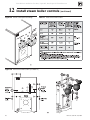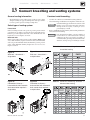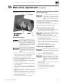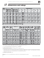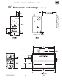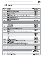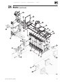
1
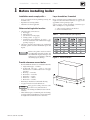
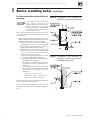
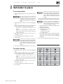
80
Water & steam boilers
for use with Gas, Light Oil, &
Gas/Light Oil – Fired Burners
Boiler Manual
INSTALLER
USER
This manual must only be used by a qualified heating installer/service
technician. Read all instructions before installing. Follow all instructions
in proper order. Failure to comply could result in severe personal injury,
death or substantial property damage.
• Consider piping and installation when determining boiler location.
• Any claims for damage or shortage in shipment must be filed immediately
against the transportation company by the consignee.
• This manual is for use only by your qualified heating installer/service
technician.
• Boiler and burner must be installed by a qualified service technician.
• We recommend regular service by a qualified service technician, at least
annually.
When calling or writing about the boiler— Please have the boiler model
number from the boiler rating label and the CP number from the boiler
jacket.
Part No. 550-141-935/1202
Weil-McLain 80 Boiler For Gas, Light Oil, Gas/Light Oil Fired Burners
Contents
Page
1.
Before installing boiler .................................................................................. 3
2.
Set boiler in place........................................................................................... 5
3.
Assemble block .............................................................................................. 6
4.
Perform hydrostatic pressure test ................................................................ 8
5.
Complete block assembly ............................................................................. 9
6.
Install flue collector...................................................................................... 10
7.
Connect water boiler piping ........................................................................ 14
8.
Connect steam boiler piping ....................................................................... 16
9.
Install jacket .................................................................................................. 20
10. Pipe tankless heaters ................................................................................... 27
11. Install water boiler controls ......................................................................... 28
12. Install steam boiler controls ........................................................................ 29
13. Connect breeching and venting system .................................................... 31
14. Install burner ................................................................................................. 32
15. Wiring and fuel piping .................................................................................. 32
16. Make final adjustments ................................................................................ 32
17. Dimensions and ratings ............................................................................... 34
18. Parts .............................................................................................................. 36
Handling ceramic fiber and fiberglass materials ....................................... 38
Hazard Definitions
The following defined terms are used throughout this manual to bring attention to the presence of hazards of various
risk levels, or to important information concerning the life of the product.
Indicates presence of hazards that will cause severe personal injury, death or substantial property
damage if ignored.
Indicates presence of hazards that can cause severe personal injury, death or substantial property
damage if ignored.
Indicates presence of hazards that will or can cause minor personal injury, death or substantial
property damage if ignored.
Indicates special instructions on installation, operation or maintenance that are important but not
related to personal injury.
Read all instructions before installing.
Failure to follow all instructions in proper
order can cause severe personal injury,
death or substantial property damage.
2
Do not use petroleum-based cleaning or
sealing components in boiler system.
Severe damage to system components can
result, causing substantial property
damage.
Part No. 550-141-935/1202
• Installation
1
• Start-Up
• Maintenance
• Parts
Before installing boiler
Installation must comply with —
Lay a foundation, if needed:
•
Floor construction and condition must be suitable for
weight of boiler when filled with water. See page 34 for
approximate boiler operating weight.
A level concrete or brick foundation (constructed per
Table 1 and Figure 1) is required when:
•
•
State, provincial and local plumbing, heating and
electrical codes.
Regulations of servicing utilities.
National codes where applicable.
Before selecting boiler location
1. Check for nearby connections to:
a. Fuel supply
b. Electrical power
c. System water or steam piping
d. Venting systems - see page 31
e. Combustion and ventilation air supply — see
"Provide combustion and ventilation air supply
openings" on page 4.
2. Check area around boiler. Remove any combustible
materials, gasoline and other flammable vapors and
liquids.
Failure to keep boiler area clear and free
of combustible materials, gasoline and
other flammable liquids and vapors can
result in severe personal injury, death and
substantial property damage.
1. A floor could possibly become flooded.
2. Non-level conditions exist.
Table 1
Boiler foundation (see Figure 3)
Figure 1
Boiler foundation
Provide clearance around boiler
•
•
•
•
•
Provide minimum clearances to combustible materials:
1. Singlewall vent pipe – 18 inches.
2. Doublewall vent pipe – refer to vent pipe
manufacturer's recommendations for vent pipe
clearances.
3. Boiler top — 24 inches.
4. Boiler front — 48 inches.
5. Boiler flue — 9 inches.
6. Boiler rear — 9 inches.
7. Boiler sides — 6 inches.
Boiler may be installed on combustible flooring.
See pages 34 and 35 for boiler dimensions.
Flue pipe/breeching clearances take
precedence over jacket clearances.
Left side — for cleaning and tankless heater removal –
34 inches.
Allow sufficient space on remaining sides for cleaning,
servicing and burner installation. See burner literature
for length and recommended service clearances.
Part No. 550-141-935/1202
3
Weil-McLain 80 Boiler For Gas, Light Oil, Gas/Light Oil Fired Burners
1
Before installing boiler
Provide combustion and ventilation air
openings:
Do not install an exhaust fan in boiler
room. Adequate combustion and
ventilation air must be provided to assure
proper combustion and prevent
possibility of flue gas leakage and carbon
monoxide emissions, causing severe
personal injury or death.
Opening sizes must comply with state, provincial or local
codes. In their absence, use the following when boiler is in
a confined room:
• Provide two permanent openings in boiler room — one
within 12 inches of ceiling, one within 12 inches of floor.
Minimum dimension of each opening is 3 inches.
1. When all air is taken from within building, each
opening should be at least one square inch/1,000
Btuh boiler input and freely connect with areas
having adequate infiltration from outside.
2. When all air is taken from outdoors, each opening
should connect directly or by ducts from outdoors
or crawl or attic spaces that freely connect with
outdoors and sized as listed below:
a. through outside wall or vertical ducts - at least
one square inch/4,000 Btuh boiler input.
b. through horizontal ducts - at least one square
inch/2,000 Btuh boiler input.
c. where ducts are used, they should be same crosssectional area as free area of openings they are
connected to.
d. compensate for louver, grille or screen blockage
when calculating free air openings. Refer to their
manufacturer's instructions for size. If
unknown, use:
• wood louvers - 20-25% free air.
• metal louvers or grilles - 60-75% free air.
• screens - not less than ¼ inch mesh.
(continued)
Figure 2
Combustion and ventilation air
openings — Boiler room below grade
Figure 3
Combustion and ventilation air
openings — Boiler room partially or
completely above grade
Lock louvers in open position, or interlock with equipment
to prove open before boiler operation.
When combustion and ventilation air enters through
sidewall openings, ensure openings comply with Figures 2
and 3.
4
Part No. 550-141-935/1202
• Installation
2
• Start-Up
• Maintenance
• Parts
Set boiler in place
For packaged boiler:
1. Remove top jacket panels. Set aside until after boiler is
piped.
2.
3.
4.
5.
6.
The boiler contains ceramic fiber and
fiberglass materials. Use care when
handling these materials per instructions
on page 38 of this manual. Failure to
comply could result in severe personal
injury.
Remove lag screws (2 in front, 2 in rear) from shipping
rails.
Remove boiler from skid. Cables are already attached
to block assembly. See Table 2 for lifting weight.
• Using crane — hook middle of each cable to eye of
crane.
• Using hoist — hook middle of each cable to hoist.
Raise boiler off skid. Use pipe rollers under skid
angles to roll boiler.
Place boiler in final position. Center boiler on
foundation, if used.
Level boiler. Shim under skid angles, if necessary.
Cut off cables.
Cables are not intended for long-term
usage. Cables may corrode inside boiler,
weakening their lifting strength. Failure to
remove cables can result in severe personal
injury, death or substantial property
damage.
7. Proceed to "Perform hydrostatic pressure test," page 8.
Cables are not intended for long-term
usage. Cables may corrode inside boiler,
weakening their lifting strength. Failure to
remove cables can result in severe personal
injury, death or substantial property
damage.
6. Inspect block assembly for disjointed sections. Check
gas-tight seal of flue collector hood and cleanout plates.
Gas tight seal must be maintained to
prevent possible flue gas leakage and
carbon monoxide emissions, resulting in
severe personal injury or death.
a. Check inside section assembly for any light passing
through unsealed areas.
b. Mark all unsealed areas.
c. At unsealed areas, check for:
• damaged gaskets.
• sealing rope not in place.
• loose bolts or nuts.
d. Correct all conditions and repeat step b. If unsealed
areas still exist, contact your Weil-McLain
distributor or sales office before continuing
installation.
7. Proceed to "Perform hydrostatic pressure test," page 8.
Table 2
Lifting weights
For block assembly:
1. Remove lag screws (2 in front, 2 in rear) from shipping
rails.
2. Remove boiler from skid. Cables are already attached
to block assembly. See Table 2 for lifting weight.
• Using crane – attach free end of cables to eye of
crane.
• Using hoist – attach free end of cables to hoist. Raise
boiler off skid. Use pipe rollers under steel skid
angles to roll boiler.
3. Place boiler in final position. Center boiler on
foundation, if used.
4. Level boiler. Shim under skid angles, if necessary.
5. Cut off cables.
Part No. 550-141-935/1202
5
Weil-McLain 80 Boiler For Gas, Light Oil, Gas/Light Oil Fired Burners
3
Assemble block
Sections are top heavy. Unbolted sections
may fall if not supported, resulting in
severe personal injury or death.
Install back refractory blanket
1. Lay back section on floor with ports face up.
2. Apply adhesive to blanket.
3. Press blanket against back target wall as shown in
Figure 4.
4. Using knife, cut hole through blanket to expose
observation port opening.
Prepare back section
1. Apply 1/8" continuous bead of sealing rope adhesive in
sealing rope grooves. See Figure 4. Do not get any
adhesive on machined port surfaces.
2. Place ½" sealing rope in groove. Around curves, grasp
at 1" intervals and push together. Do not stretch.
Do not pre-cut rope. Gas tight seal must
be maintained to prevent possibility of
flue gas leakage and carbon monoxide
emissions, causing severe personal injury
or death.
3. Remove any grit from port machined surfaces with
clean rag.
Figure 4
6
Sealing rope installation
Do not use petroleum-based cleaning or
sealing compounds in boiler system.
Severe damage to system components can
result, causing substantial property
damage.
4. Place 7½" and 3½" sealing rings in appropriate port
openings. See Figure 4. If sealing ring slips out of groove,
stretch ring gently for several seconds, then reposition
in groove.
5. Apply continuous bead of silicone sealant no larger than
1/ " around entire outside edge of outer machined
16
surface of port. Refer to Figure 5. Do not apply
silicone sealant on, next to or under sealing ring.
Silicone sealant applied as specified above
prevents unburned oil vapors from
coming in contact with sealing ring. Vapor
contact can damage rings, resulting in
severe damage to boiler and substantial
property damage.
6. Position section upright on foundation (if used) and
screw 3" pipe at least 22" long into 3" return tapping.
7. Place a block under pipe to hold section upright.
Figure 5
Silicone sealant
Part No. 550-141-935/1202
• Installation
3
• Start-Up
• Maintenance
Assemble block
• Parts
(continued)
Install intermediate sections
Figure 6 Sealing ring installation and port alignment
Sections are top heavy. Unbolted sections may fall if not
supported, resulting in severe personal injury or death.
1. Remove and discard 3/8" diameter shipping tie rods.
2. Remove grit from port machined surfaces with clean rag.
Do not use petroleum-based cleaning or sealing compounds
in boiler system. Severe damage to system components can
result, causing substantial property damage.
3. Position intermediate section so aligning lugs fit into sockets of next section.
See Figure 6.
4. Install TI (tankless intermediate) and SI (supply intermediate) sections
(when used) in order shown in Table 3.
5. Draw sections together until metal-to-metal contact is made around
machined port openings (see Figure 6):
a. Oil threads on 4 draw rods. Install washer and nut on end to be tightened.
Use nut only on other end.
b. Uniformly draw sections together, starting at washer/nut end.
Table 3
Section arrangement
Important — Leave an equal amount of thread on each end
of the draw rod. This is needed to allow securing the jacket
support brackets in place (see pages 20 and 21).
c. Draw rods should be torqued to a range of 90 to 100 ft. - lbs. Do not
back off draw rods.
d. Metal-to-metal contact will be achieved around port openings. See Figure
6. If gap occurs, it should be no greater than .032". Check with feeler
gauge.
e. If, for any reason, gap around machined port opening exceeds .032",
check for rope extending from rope grooves, dirt on port openings or
sockets, or misaligned lugs. If corrections are made and gap still exists,
contact your Weil-McLain distributor or sales office before continuing
installation.
6.
After erecting first intermediate section, check both
sections for plumb. Failure to plumb sections can cause
misaligned piping and breeching, possibly resulting in
property damage.
7. Repeat steps 1-5 from “Prepare back section,” page 6.
Install bottom refractory blanket on combustion
chamber floor inside section block
1. Unroll blanket only to depth of back section and first intermediate section.
2. Spread adhesive on bottom side of blanket.
3. Press blanket into center bottom of sections.
4. Unroll and install blanket per steps 2 and 3 as each intermediate and front
section are installed.
5. At front section, cut off blanket 2 ½" from burner opening. Discard unused
blanket.
Do not use petroleum-based cleaning or
sealing compounds in boiler system.
Severe damage to system components can
result, causing substantial property
damage.
b. Check each section for proper sealing rope position
before proceeding to next section.
Failure to position sealing rope properly
can cause boiler to not seal gas-tight. Gas
tight seal prevents possible flue gas leakage
and carbon monoxide emissions,
resulting in severe personal injury or
death.
Prepare remaining sections
1. Follow “Prepare intermediate section” for remaining intermediate and front
sections:
a. Remove any grit from threads inside tapped holes with clean rag.
Part No. 550-141-935/1202
If using tankless heater (TI) sections
1. Install tankless heaters and gaskets or heater cover plates
and gaskets. Use 3/8" x 3/4" studs, washers and nuts.
7
Weil-McLain 80 Boiler For Gas, Light Oil, Gas/Light Oil Fired Burners
4
Perform hydrostatic pressure test
Prepare boiler and test:
1. See pages 28 and 29 for tapping locations. Install:
a. Boiler drain (not furnished).
b. Water pressure gauge — for test only. Be sure gauge can handle test pressure — see step 3.
c. Air vent in upper tapping (K).
2. Plug remaining tappings.
Do not pressure test with any control installed. Damage to control can occur due
to overpressure.
3. Fill boiler. Vent all air. Pressure test at least 10 minutes at a pressure not less than the following:
Steam boiler:
Between 45 and 55 psig.
Water boiler:
1½ times maximum allowable working pressure (MAWP) stamped on the boiler nameplate,
located on boiler jacket front panel.
Do not exceed above test pressures by more than 10 psig.
Do not leave boiler unattended. Cold water fill could expand and cause excessive
pressure, resulting in severe personal injury, death or substantial property damage.
4. Check for maintained gauge pressure and leaks. Repair if found.
Leaks must be repaired at once. Failure to do so can damage boiler, resulting in
substantial property damage.
Do not use petroleum-based cleaning or sealing compounds in boiler system. Severe
damage to system components can result, causing substantial property damage.
5. Drain boiler and remove air vent, boiler drain and gauge. Remove plugs from tappings that will
be used for controls and accessories.
8
Part No. 550-141-935/1202
• Installation
5
• Start-Up
• Maintenance
• Parts
Complete block assembly
Install burner mounting plate on front section
1. Install four ½" x 4¾" studs to secure burner mounting plate to section:
a. Thread and lock together two nuts on rounded end of stud. Thread flat end of stud into one
of four holes located around opening.
b. Remove nuts.
c. Repeat steps a and b for remaining studs.
2. Install burner mounting plate:
a. Apply 1/8" continuous bead of sealing rope adhesive in groove around opening in section.
b. Position ½" sealing rope in groove. Overlap ends at least one inch.
c. Install burner mounting plate. Use ½" washers and nuts.
Install observation port assemblies on front and back sections:
1. Install front observation port assembly:
a. Apply 1/8" continuous bead of sealing rope adhesive in groove on observation port.
b. Position 3/8" sealing rope in groove.
c. Secure assembly to section. Use 5/16 " - 18 x ¾" slotted head screws.
2. Repeat above steps for back observation port assembly.
Install cleanout plates
1.
2.
3.
4.
Cleanout plates must be installed gas-tight to prevent possibility of flue gas leakage
and carbon monoxide emissions, resulting in severe personal injury or death.
See Figure 7. Position two ¼" x 1¾" carriage bolts in cleanout opening. Secure with washers and
nuts.
Place blanket insulation piece against cleanout plate.
Mount cleanout plate over opening. Secure with nuts and washers.
Repeat steps 1 through 3 for remaining cleanout plates.
The boiler contains ceramic fiber and
fiberglass materials. Use care when
handling these materials per
instructions on page 38 of this
manual. Failure to comply could
result in severe personal injury.
Part No. 550-141-935/1202
Figure 7
Cleanout plate assembly
9
Weil-McLain 80 Boiler For Gas, Light Oil, Gas/Light Oil Fired Burners
6
Install flue collector
Flue collector assembly
1. Figure 10, page 11, shows flue collector components
and locations. Figure 11, page 13, shows collector hoods
for all models. Follow all instructions in this manual to
ensure correct installation of the flue collector.
2. Model 80 boilers are available with either rear flue or
top flue. Verify that you have the correct components
for your application. You can convert a Model 80 from
rear to top or top to rear flue using a flue conversion
kit, available from your Weil-McLain distributor.
The flue outlet for top flue models must
be located as shown in this manual.
Install collector hold-down bolts
1. Figure 10, lower left — Install a collector hold-down
bolt assembly at each section joint, and on both sides
of the boiler section assembly. Set aside the flanged nuts
for securing the collector assembly when it is ready.
2. Each hold-down bolt assembly consists of a 5/16" x 2"
carriage bolt, flat washer, regular hex nut and a flanged
nut as shown.
Prepare flue collector hood assembly
Make sure gaskets are intact, not torn or
otherwise damaged. These conditions can
cause possible flue gas leakage and carbon
monoxide emissions, resulting in severe
personal injury or death.
The boiler contains ceramic fiber and
fiberglass materials. Use care when
handling these materials per instructions
on page 38 of this manual. Failure to
comply could result in severe personal
injury.
1. Stand flue collector hood front module (item 4) on end
as in Figure 8, left side.
Figure 8
2. Wipe all flanged surfaces with clean rag.
3. Lay flue collector hood gasket (item 2) on flange.
4. Place flue collector end cap (item 1) on gasket. Align
bolt holes. Secure with seven 5/16" x 5/8" flanged bolts
and flanged nuts. Tighten to between 30 and 35
inch-pounds torque. (See WARNING on page 12, top
right column.)
5. For 880 - 1280:
a. Stand remaining hood module on end, as in
Figure 8, right side.
b. Wipe all flanged surfaces with clean rag.
c. Lay gasket on flange.
d. Carefully place open end of first module on top of
gasket, aligning flanged surfaces.
e. Secure with seven 5/16" x 5/8" flanged bolts and
flanged nuts. Tighten to between 30 and 35 inchpounds torque. (See WARNING on page 12.)
6. Attach flat-stitched sealing rope to hood assembly. See
Figure 9:
a. Lay hood on floor with flanged side up.
b. Wipe flanged surface with clean rag to remove dirt
and oil.
c. Apply double-faced tape to flanged surface.
d. Apply rope to tape beginning on one side of open
end of hood, leaving ¼" extending past edge. Bend
rope around corners. DO NOT cut or stretch
rope.
Do not pre-cut rope. All collector hood
joints must be sealed gas-tight to prevent
possible flue gas leakage and carbon
monoxide emissions, resulting in severe
personal injury or death.
e. Continue around entire flange. At other open end,
leave ¼" rope extending past edge of flange. Cut off
excess rope.
Double-faced tape serves only to hold
sealing rope in place during installation.
It will disintegrate over time. If collector
hood and sealing rope are removed for any
reason, install new tape and new gasket.
Collector hood preparation
Figure 9
10
Flue collector sealing rope installation
Part No. 550-141-935/1202
• Installation
6
Figure 10
• Start-Up
• Maintenance
Install flue collector
• Parts
(continued)
Flue collector components, typical (Model 880 collector configurations shown)
Part No. 550-141-935/1202
11
Weil-McLain 80 Boiler For Gas, Light Oil, Gas/Light Oil Fired Burners
6
Install flue collector
Before installing flue collector
1. See Figure 10, page 11, for general assembly of flue
collector components.
2. See Figure 11, page 13 for the placement of flue collector
hoods on each model.
3. Prepare mounting holes in boiler rear section.
a. The boiler rear section has tapped holes for mounting
rear flue collector component.
b. Remove any grit from threads inside tapped holes with
clean rag.
Rear flue boilers only:
1. See Figure 10, page 11 and Figure 11, page 13.
2. Place collector hood transition on rear section:
a. Wipe item 10, Figure 10, collector hood transition
flange surfaces with a clean rag.
b. Apply a few pieces of double-faced tape on the
collector hood transition flange.
c. Place the collector hood transition gasket (item 8,
Figure 10) on the collector hood transition flange.
Align holes in gasket with holes in flange. Press gasket
firmly in place.
d. Position collector hood transition on back of boiler
rear section, aligning collector hood transition flange
holes with tapped holes in boiler rear section.
e. Insert a 5/16" x 5/8" flanged bolt through the bottom
center hole and finger tighten to hold transition in
place.
f. Install six remaining bolts securing collector hood
transition to rear section. Finger-tighten only.
3. Place collector hood assembly on sections:
a. Carefully set collector hood assembly on top of section
assembly. Align slotted holes in collector hood flanges
with the hold-down bolts in the sections.
b. Place the collector hood assembly so its rear flange is
against the collector hood transition flange gasket.
c. Thread flanged nuts onto hold-down bolts and fingertighten only.
d. Insert five 5/16" x 5/8" flanged bolts through holes in
collector hood transition and collector hood assembly
rear flange. Thread on nuts and finger-tighten only.
4. Tighten flue collector bolts and nuts:
a. Gradually tighten all bolts and nuts on flue collector
assembly and boiler. Tighten to between 30 and 35
inch-pounds torque. See WARNING, upper right.
b. Alternate locations as you tighten the fasteners to
ensure all parts are evenly drawn down, with no gaps
or distortion of parts.
(continued)
DO NOT overtighten bolts in flue collector hood assembly.
Gasket material could extrude, causing possible flue gas leakage
and carbon monoxide emissions, resulting in severe personal
injury or death.
Top flue boilers only:
1. See Figure 10, page 11 and Figure 11, page 13.
2. Place rear flue cap on rear section:
a. Wipe item 9, Figure 10, rear flue cap gasket surface with a clean rag.
b. Apply a few pieces of double-faced tape on the rear flue cap gasket surface.
c. Place the rectangular gasket (item 8, Figure 10) on the flue cap, aligning
holes in gasket with holes in rear flue cap. Press firmly in place.
d. Position rear flue cap on back of boiler rear section, aligning rear flue cap
holes with tapped holes in boiler rear section.
e. Insert a 5/16" x 5/8" flanged bolt through the bottom center hole and finger
tighten to hold rear flue cap in place.
f. Install six remaining bolts securing rear flue cap to rear section. Fingertighten only.
3. Place collector hood assembly on sections:
a. Carefully set collector hood assembly on top of section assembly. Align
slotted holes in collector hood flanges with the hold-down bolts in the
sections.
b. Place the collector hood assembly so its rear flange is against the rear flue
cap gasket.
b. Thread flanged nuts onto hold-down bolts and finger-tighten only.
c. Insert five 5/16" x 5/8" flanged bolts through holes in rear flue cap and
collector hood assembly rear flange. Thread on nuts and finger-tighten only.
4. Tighten flue collector bolts and nuts:
a. Gradually tighten all bolts and nuts on flue collector assembly and boiler.
Tighten to between 30 and 35 inch-pounds torque. See WARNING, above.
b. Alternate locations as you tighten the fasteners to ensure all parts are evenly
drawn down, with no gaps or distortion of parts.
5. Install damper and flue caps (see Figure 11, page 13):
a. Wipe item 5, Figure 10, flue damper flange surface and flue collector
assembly surfaces with a clean rag.
b. Position round gasket (item 7, Figure 10) on flue collector assembly in the
flue location shown in Figure 11, page 13. Align bolt holes.
c. Place flue damper assembly on gasket. (See NOTICE, below.) Insert #10 x
½" screws through the holes. Alternate from screw to screw and tighten all
screws evenly and securely.
Model 380 top flue applications — always mount the damper
assembly with the damper adjustment plate pointed toward
the rear of the boiler as shown in Figure 11. Otherwise, the
jacket top panels may be difficult to install.
e. Install flue cap on remaining top opening (if any) using steps a through c,
above.
5. Install damper and flue caps:
a. Wipe item 5, Figure 10, flue damper flange surface
with a clean rag.
b. Apply a few pieces of double-faced tape to the flue
damper flange. Position flue collar gasket on damper
and press firmly in place. Align all holes before
securing.
c. Position flue damper assembly against collector hood
transition. Insert a #10 x ½" screw through the top
center hole. Lightly tighten to hold flue damper in
position.
d. Insert remaining #10 screws into flue damper flange
and lightly tighten. Alternate from screw to screw and
tighten all screws evenly and securely.
e. Install flue caps on flue collector top opening(s) using
steps 5a through 5d.
12
After installing flue collector, ALL BOILERS
1. Check for gas-tight seal of all flue collector hood components.
All collector hood joints must be sealed gas-tight to prevent
possible flue gas leakage and carbon monoxide emissions,
resulting in severe personal injury or death.
a. Open flue damper. Visually inspect inside section assembly and flue collector
assembly for any light passing through unsealed areas.
b. Mark all unsealed areas.
c. Check unsealed areas for cause — damaged gaskets, sealing rope not in
place, or loose bolts or nuts.
d. Correct all conditions and repeat inspection procedure.
e. If unsealed areas cannot be eliminated, discontinue the boiler installation.
Contact your Weil-McLain distributor or sales office for assistance.
Part No. 550-141-935/1202
• Installation
6
Figure 11
• Start-Up
• Maintenance
Install flue collector
• Parts
(continued)
Flue collector components by model (see Figure 10, page 11 for flue collector components not shown below)
Part No. 550-141-935/1202
13
Weil-McLain 80 Boiler For Gas, Light Oil, Gas/Light Oil Fired Burners
7
Connect water boiler piping
General water piping information:
•
•
•
Table 6
Recommended minimum pipe sizes for
known flow rates.
Table 7
ASME drain valve size
System water supply and return piping should be installed and piping
connections attached to boiler before erecting jacket or installing controls.
Do not pipe in through supply and out through return. This creates reverse
water flow through boiler that must not be used.
When three-way valves are used for temperature modulation, install slowopening (minimum 10-minute) valves and boiler mixing pump to minimize
potential of boiler thermal shock. See W-M Bulletin AE-8402.
Install piping:
Install piping as shown in Figure 12 for single boilers. For multiple boilers, see
Figure 13, page 15.
Improperly piped systems or undersized piping can contribute
to erratic boiler operation and possible boiler or system
damage.
1. Connect supply and return piping:
a. Size according to tables below.
1) For unknown flow rates, size piping per Table below, using 20°F.
temperature rise through boiler.
2) For known flow rates or higher flow rate through boiler, size
piping per Table below.
Flow at higher rates than shown in Table below for pipe size
can damage boiler, causing substantial property damage.
b. Locate circulator in supply piping.
c. For return piping, use full diameter pipe for 10 times that diameter before
making any reduction. For example, a 4-inch return should not be
reduced any closer to boiler return tapping than 40 inches.
d. Install system blow-off (drain) valve in lowest part of return piping close
to boiler. ASME minimum size requirements are shown in Table 5.
2. Install expansion tank:
a. Closed type – connect to 1" tapping “K” (refer to pages 28 and 29).
Use 1” N.P.T. piping. Any horizontal piping must pitch up toward tank
at least 1 inch per each 5 feet of piping.
b. Diaphragm type – Refer to tank manufacturer’s literature for location.
Install automatic air vent in “K” tapping.
c. Connect cold water fill to expansion tank piping. See Figure 12, page 14.
Also shown are recommended valves and water meter, when used. Water
meter will detect added make-up water, indicating leaks in system.
Table 5
14
Figure 12
Water boiler piping, typical
Recommended minimum pipe sizes when flow rate is
not known (see Figure 12)
Part No. 550-141-935/1202
• Installation
7
• Start-Up
• Maintenance
• Parts
Connect water boiler piping
3. Piping for multiple boilers (see Figure 13):
A Size secondary boiler pump GPM based on
following formulas:
Gross output
Temperature rise x 500
(continued)
Figure 13 Multiple water boiler piping
= GPM
Temperature rise, °F = 230°F – Return water temperature
Gross output is in Btuh.
Calculate only secondary piping circuit resistance.
Boiler resistance will be about equal to three 90
degree elbows of secondary pipe size. Operate each
boiler and its secondary pump from a Weil-McLain
boiler control panel. Do not maintain boiler at
predetermined water temperature.
B Primary pump GPM and head calculation should
not include secondary boiler circuits. Primary
pump can operate continuously during heating
season.
C Space 12" maximum or as close as practical.
D Check valve.
E Hand valve.
Expansion tank(s), relief valves and other accessories are
required but not shown.
Part No. 550-141-935/1202
15
Weil-McLain 80 Boiler For Gas, Light Oil, Gas/Light Oil Fired Burners
8
Connect steam boiler piping
General steam piping information:
•
Hartford loop piping arrangement and wet return are
required for steam boilers. Use the Hartford loop for
both pumped-return and gravity-return systems.
• Maintain 24-inch minimum from waterline to bottom
of header (56¼" from bottom of section).
• When using condensate receiver, feed pump must be
energized by boiler-mounted pump controller. Install
piping:
Install piping as shown on pages 16 through 18 for single
boilers. See page 19 for additional requirements when
piping multiple boilers.
Improperly piped systems or undersized
piping can contribute to erratic boiler
operation and possible boiler or system
damage. Piping system must be installed
as shown, using pipe sizes shown. Pipe
sizes shown are for two-pipe, pumpedreturn systems. Adjust pipe sizing as
needed when connecting to gravityreturn systems. Consult local WeilMcLain distributor or sales office before
installing alternate piping.
1. Connect supply and return piping:
a. See Table 8.
1) Size condensate return piping by pump.
2) Size gravity condensate return same as equalizer
“J” pipe size.
b. Install system drain valve in lowest part of return
piping close to boiler. ASME size requirements are
shown in Table 7, page 14.
Table 8
16
c. Connect cold water fill piping as shown in Figure 14.
Also shown are recommended valves and water
meter, if used. Water meter will detect added
makeup water, indicating leaks in system.
2. Condensate piping:
a. Satisfactory operation of any steam heating system
depends on adequate return of condensate to
maintain steady water level.
b. Avoid adding excessive amounts of raw make-up
water.
c. Where condensate return is not adequate, a low
water cutoff with pump control, condensate
receiver, and condensate boiler feed pump should
be installed. Refer to page 18, Figure 18 for piping
and Table 9 for sizing.
3. Multiple steam boiler piping
a. See page 19.
Figure 14
Cold water fill piping
Steam boiler pipe size for typical 2-pipe steam systems
Part No. 550-141-935/1202
• Installation
8
• Start-Up
• Maintenance
• Parts
Connect steam boiler piping
(continued)
Figure 15 Model 380 through 580 steam boiler piping — NOTE
minimum 24 inches between boiler water line and bottom
of header.
Figure 16 Model 680 through 980 steam boiler piping — NOTE
minimum 24 inches between boiler water line and bottom
of header.
Part No. 550-141-935/1202
17
Weil-McLain 80 Boiler For Gas, Light Oil, Gas/Light Oil Fired Burners
8
Connect steam boiler piping
(continued)
Figure 17 Model 1080 through 1280 steam boiler piping — NOTE minimum 24 inches between boiler water line and
bottom of header.
Figure 18 Condensate piping to boiler
18
Table 9
Condensate receiver capacity
Part No. 550-141-935/1202
• Installation
8
• Start-Up
• Maintenance
• Parts
Connect steam boiler piping
Figure 19
Multiple Steam Boiler Piping Gravity Condensate Return
A Pipe as shown for gravity return systems, connecting
point A to the wet gravity return.
For pumped-return systems, install boiler water level
control on each boiler with body mark at level indicated
in Figure 30 on page 30. Provide at point A either:
• Separate feed pumps and check valves for each
boiler, or . . .
• Single feed pump, with separate solenoid valve for
each boiler.
B For pumped-return systems, install a combination float
and thermostatic trap on each boiler to prevent flooding
of one boiler while other boiler is firing. Install trap in
skim tapping (see page 29). Connect traps to
condensate receiver.
Gravity-return systems are self-levelling if the wet
returns are piped to the common system wet return.
C Install boiler piping as shown in this manual (pages 16
through 19).
Part No. 550-141-935/1202
(continued)
D Install stop valves per ASME code requirements.
For pump-return systems, if using automatic steam
valves, use only slow-opening automatic valves. Use a
Weil-McLain Boiler Control System (such as a BCP
panel) to open each steam valve automatically before
firing burner.
E Construct common supply drop header with pipe size
at least same size as largest boiler header size.
F Use:
• A Weil-McLain Boiler Control System (such as a BCP
panel) with header-mounted pressure control(s) to
sequence boilers, or . . .
• A steam pressure controller.
G Install drip line in common supply drop header.
Gravity-return: Pipe drip line to wet return.
Pumped-return: Use combination float and thermostatic
trap and drain to condensate receiver.
19
Weil-McLain 80 Boiler For Gas, Light Oil, Gas/Light Oil Fired Burners
9
Install jacket
Before installing jacket
1. Packaged boilers
• Install top jacket panels per instructions in this
manual.
2. Non-packaged boilers
• Follow the instructions in this section to install all
jacket panels.
• Make sure the following are completed before
installing jacket:
• Boiler hydrostatically pressure-tested. See page 8.
• Plugs for unused tappings installed. See control
tapping table, page 28 or 29.
• Supply and return piping installed. See pages 14
through 19.
• Cleanout plates, flue collar and flue collector hood
installed. See pages 9 through 13.
3. These parts must be on boiler:
• plugs for unused tappings
• supply and return piping
• steam supply header
• cleanout plates
• tankless heater(s) (when used)
• tankless heater cover plate(s) (when used)
• tankless heater piping (when used)
• flue damper assembly
• flue collector hood
• observation port assemblies
4. These parts may be on boiler:
• burner mounting plate
• burner
5. These parts must be off boiler:
• water or steam gauge
• limit control
• low water cutoff
• gauge glass and gauge glass cocks
• tri-cocks
• drain cock
20
The boiler contains ceramic fiber and
fiberglass materials. Use care when
handling these materials per instructions
on page 38 of this manual. Failure to
comply could result in severe personal
injury.
Remove jacket parts from cartons
1. Locate jacket cartons.
2. Remove jacket parts from cartons as needed. Leave in
cartons as long as possible to avoid damage.
Install support brackets and rails
1. Place upper and lower support brackets over draw rods
as shown in Figure 20, page 21.
2. Fasten securely with 5/8" nuts where shown.
Models 380, 480, 580, 680 and 780 do not
require lower support brackets. Only
upper brackets are required.
3. Space the brackets along the length of the boiler so there
are close to an equal number of sections on either side
of the bracket(s).
4. Attach the upper and lower rails on each side of the
boiler by securing with #10 x ½" Phillips pan head
screws. DO NOT tighten the screws more than fingertight.
Install jacket front and rear panels
1. Attach the front and rear jacket panels to the upper
and lower channels using #10 x ½" Phillips pan head
screws, as shown in Figure 20.
2. Rear flue boilers only — remove rear jacket panel flue
collector transition knockout with tin snips before
installing on boiler.
Part No. 550-141-935/1202
• Installation
9
• Start-Up
Install jacket
Figure 20
Part No. 550-141-935/1202
• Maintenance
• Parts
(continued)
Installing jacket support brackets and rails and jacket front and rear panels
21
Weil-McLain 80 Boiler For Gas, Light Oil, Gas/Light Oil Fired Burners
9
Install jacket
(continued)
Install jacket side panels
Install jacket top panels
1. Remove jacket side panels from cartons.
1. Place jacket top panels as shown in Figure 25, page 26.
• Remove knockouts for riser pipes or flue outlet using tin snips.
2. Fold out tab in top panel side flange next to top flue knockout to
prevent top panel from sagging (see below).
2. Insert a plastic plug (provided in jacket cartons) in the 1-inch
hole in the center of each of the jacket side panels.
3. Before installing side panels, square up the jacket support rails.
• Place any of the jacket side panels on the rails as shown in
Figure 21.
• Butt the side panel against the jacket front panel.
• Push/pull on the upper and lower rails until the fit-up of the
side panel, front panel and rails is square.
• Place a jacket top panel in position against the jacket front
panel to ensure the top alignment is square. Adjust the jacket
support rails forward or backward if needed for square
alignment.
• Tighten the screws securing the upper and lower rails to the
support brackets.
• Tighten the screws securing the front and back panels to the
rails.
4. Apply all jacket side panels in the order shown in Figures 22, 23
or 24.
• Remove jacket knockouts as required for tankless heaters.
• Note that panel sequence is not important for boilers not
equipped with tankless heater intermediate sections.
Figure 21
22
3. Install trim collar around damper assembly on top flue boilers.
Install jacket trim
1. Press jacket trim over jacket side panels as shown in Figure 21.
Place each jacket trim so the side of the trim with small holes
faces toward the boiler.
Installing (removing) jacket side panels and top panels
Part No. 550-141-935/1202
• Installation
9
• Start-Up
Install jacket
• Maintenance
• Parts
(continued)
Figure 22 Jacket side panel placement — Models 380, 480, 580 and 680
Part No. 550-141-935/1202
23
Weil-McLain 80 Boiler For Gas, Light Oil, Gas/Light Oil Fired Burners
9
Figure 23
24
Install jacket
(continued)
Jacket side panel placement — Models 780, 880 and 980
Part No. 550-141-935/1202
• Installation
9
Figure 24
• Start-Up
Install jacket
• Maintenance
• Parts
(continued)
Jacket side panel placement — Models 1080, 1180, and 1280
Part No. 550-141-935/1202
25
Weil-McLain 80 Boiler For Gas, Light Oil, Gas/Light Oil Fired Burners
9
Install jacket
(continued)
Figure 25 Jacket top panel placement
26
Part No. 550-141-935/1202
• Installation
10
• Start-Up
• Maintenance
• Parts
Pipe tankless heaters
To pipe tankless heaters:
1. Size piping no smaller than heater inlet and outlet.
2. Automatic mixing valve must be installed. See Figure 26.
Follow manufacturer’s instructions to install.
3. Flow regulating valve must be installed. Size according
to continuous draw of heater. See Table 10. Follow
manufacturer’s instructions to install.
4. Operating control with small adjustable differential
scale is recommended. Install in temperature control
tapping in heater plate.
5. Multiple tankless heaters (see Figure 26):
a. Use cold water supply header with individual risers
to each heater. Size header by increasing one pipe
size for each additional heater.
b. Use hot water outlet header with individual risers
to each heater. Size header by increasing one pipe
size for each additional heater.
c. Do not pipe multiple heaters in series.
6. In hard water areas, soften cold domestic water supply
to heaters to prevent lime build-up.
Table 10
Tankless Heater Ratings
Tankless
heater model
Continuous draw
(no recovery period)
GPM
Inlet and outlet
tappings
78-24
6.5
¾"
Figure 26
Tankless Heater Piping
Hot water can scald!
• Consumer Product Safety Commission and some states recommend domestic hot water
temperature of 130°F or less.
• When installing an automatic mixing valve, selection and installation must comply with valve
manufacturer's recommendations and instructions.
• Water heated to a temperature suitable for clothes washing, dish washing and other sanitizing
needs will scald and cause injury.
• Children, elderly, infirm or physically handicapped persons are more likely to be injured by hot
water. Never leave them unattended in or near a bathtub, shower or sink. Never allow small
children to use a hot water faucet or draw their own bath. If anyone using hot water in the
building fits this description, or if state laws or local codes require certain water temperatures at
hot water faucets, take special precautions:
— Install automatic mixing valve set according to those standards.
— Use lowest practical temperature setting.
— Check water temperature immediately after first heating cycle and after any adjustment.
Part No. 550-141-935/1202
27
Weil-McLain 80 Boiler For Gas, Light Oil, Gas/Light Oil Fired Burners
11
Install water boiler controls
Install controls:
Table 11
Water control tappings (see Figure 27)
1. Install furnished controls where shown in Table 11 and
Figure 27.
Failure to properly install, pipe and wire
boiler controls can result in severe damage
to boiler, building and personnel; and is
not covered by boiler warranty.
2. Relief valve must be installed with spindle in vertical
position. Use fittings provided with boiler. Do not make
any other connection in that piping.
3.
4.
5.
6.
Relief valve discharge line must be piped
using rigid material suitable for 375°F,
threaded one end, near floor close to drain
to eliminate potential of severe burns. Do
not pipe to any area where freezing could
occur. Do not plug, valve or place any
obstruction in discharge line.
When installing low water cuttoff
a. Must be installed if boiler is located above radiation
level.
b. May be required on water boilers by certain state,
local or territorial codes or insurance companies.
c. Install low water cutoff designed for water
installations where shown in Table 11 and Figure 27.
If installation is to comply with ASME installation
requirements, an additional high temperature limit is
needed. Purchase and install in supply line between
boiler and isolation valve or in tapping “A.”
Dual limit control settings:
• Low – set according to design requirements.
• High – at least 20° higher than low limit, 240°F
maximum.
Install optional controls per control manufacturer’s
instructions.
Figure 27
28
Water control locations
Part No. 550-141-935/1202
• Installation
12
• Start-Up
• Maintenance
• Parts
Install steam boiler controls
Install controls:
Table 12
Steam control tappings (see Figure 28)
1. Install controls where shown in Table 12 and Figure 28.
Failure to properly install, pipe and wire
boiler controls can result in severe damage
to boiler, building and personnel; and is
not covered by boiler warranty.
a. Install steam pressure operating and high limit
controls and pressure gauge. See Figure 28,this page,
and Figure 29, page 30.
Pressure limit control settings:
• Low – set according to design requirements.
• High – set at least 2 psi higher than low limit,
15 psi maximum.
b. Relief valve must be installed with spindle in vertical
position. Use fittings provided with boiler. Do not
make any other connection in that piping.
Pipe relief valve discharge through vertical
piping to atmosphere. Use rigid material
suitable for 375°F, threaded one end only.
Install drain pan elbow to drain
condensate. Pipe near floor close to floor
drain to eliminate potential of severe
burns. Do not pipe to any area where
freezing could occur. Do not plug, valve
or place any obstruction in discharge line.
c. Install water level controls and gauge glass as shown
in Figure 30 and Table 13, page 30.
1. Fittings for controls to be furnished by others.
2. If water level control is not shown in Table 13,
page 30, locate casting mark on control and
install per manufacturer’s instructions.
Do not use water level controls with quick
hook-up fittings. Nuisance shutdowns
will occur.
Figure 28
Steam control locations
Part No. 550-141-935/1202
29
Weil-McLain 80 Boiler For Gas, Light Oil, Gas/Light Oil Fired Burners
12
Install steam boiler controls
Figure 29
Steam control siphon and fittings
Figure 30
Water level control locations (see Table 13)
30
Table 13
(continued)
Water level control locations
Part No. 550-141-935/1202
• Installation
13
• Start-Up
• Maintenance
• Parts
Connect breeching and venting systems
General venting information
Construct metal breeching:
•
•
•
Model 80 boilers operate with positive overfire pressure. Adjust
damper assembly (see page 33) during burner start-up to achieve
0.1" W.C. positive pressure at damper sample hole.
Select type of venting system
Forced draft
Boiler, breeching and stub vent operate at positive pressure. Entire
system must be gas-tight to prevent leaks. Stub vent height must be
limited to prevent negative draft with 3-foot minimum stub vent
height above roof. See Figures 31 and 32.
Balanced draft
Boiler operates with positive pressure overfire. Chimney may provide
excess draft which may require a barometric draft control installed
and set to provide minimum draft to maintain 0.1" positive pressure
at flue collar. Minimum chimney height above roof is 3 feet. See
Figures 33 and 34.
•
See Table 14 or Table 15 for minimum breeching diameter.
Select material type and thickness in compliance with local codes.
Conventional flue pipe should not be used as it could
leak flue gases and carbon monoxide emissions
through seams and joints, resulting in severe
personal injury or death.
Refer to ASHRAE Guide for chimney and breeching calculations
and construction and lining.
Figure 31
Stub vent – forced draft —
single boiler
Figure 32
Stub vent – forced draft —
multiple boilers
Figure 33
Conventional chimney –
balanced draft with barometric
draft control when required —
single boiler
Figure 34
Conventional chimney –
balanced draft with barometric
draft control when required —
multiple boilers
Part No. 550-141-935/1202
Long horizontal breechings, excessive number of
tees and elbows or other obstructions restricting
combustion gas flow can result in possibility of
condensation, flue gas leakage and carbon monoxide
emissions, causing severe personal injury or death.
Table 14
Minimum breeching diameter —
forced draft venting
Table 15
Minimum breeching diameter —
balanced draft venting
31
Weil-McLain 80 Boiler For Gas, Light Oil, Gas/Light Oil Fired Burners
14
Install burner
To install burner:
1. Unpack burner.
2. Place gasket around air tube and against burner mounting flange.
If sealing rope is used, apply 1/8" continuous bead of rope adhesive
around burner mounting flange and apply sealing rope to make
gas-tight seal.
3. Mount burner into opening in burner mounting plate.
15
4. Level burner using burner support brackets where required.
5. Secure with furnished bolts.
6. Retain burner information packet. Keep with boiler.
Wiring and fuel piping
Electric shock hazard. Can cause severe personal
injury or death if power source is not disconnected
before installing or servicing boiler and burner.
To wire burner and boiler controls:
1. Install all wiring in compliance with:
• National Electrical Code ANSI/NFPA 70.
• Any additional national, state, or local codes.
2. Follow burner manual and wiring diagram found in burner
information packet.
3. Use 14 ga. wire for operating and safety circuit wiring.
4. Where burner motor voltage differs from control voltage, supply
proper voltage to each. Size fused disconnect(s) and conductors
per National Electrical Code ANSI/NFPA 70.
16
Maintain gas-tight seal between burner mounting
flange and plate to prevent damage to air tube.
To install gas and/or oil piping:
1. Install all piping in compliance with:
• Local, state or national codes and regulations.
• Seperate burner manual provided with burner.
2. Use pipe joint compound (pipe dope) resistant to corrosive action
of fuel oil or liquified petroleum gases. Apply sparingly to male
threads of pipe joints. Do not use any kind of pipe tape.
3. Oil piping – use flare-type fittings, not compression type.
Do not use compression or soldered fittings. No safe
repair can be made. Severe personal injury, death
or substantial property damage will result.
Propane boilers — see WARNING on page 39
regarding propane gas odorant.
Make final adjustments
To fill water boilers:
Adjust burner and damper assembly:
1. Close manual air vents and drain cocks.
2. Fill to correct system pressure. Correct
pressure will vary with each installation.
3. Starting on lowest floor, open air vents one
at a time until water squirts out. Close vent.
Repeat with remaining vents.
4. Refill boiler to correct pressure.
1. Lock open flue transition damper.
2.
3.
4.
To fill steam boilers:
1. Do not fill (except for leakage test) until
boiler is ready to be fired.
2. Fill to normal waterline, halfway up gauge
glass.
3. Recommend boiler water pH 7.0 to 8.5.
32
5.
6.
7.
Make final burner adjustments using combustion test equipment to
assure proper operation. Do not fire boiler without water. Sections will
overheat, damaging boiler and resulting in severe property damage.
Refer to burner manual for start-up and service.
Let burner advance to high fire. Heat boiler to design conditions.
Using combustion test equipment, adjust burner for:
a. 12% (± ¼%) CO2 for No. 2 fuel oil, 0 smoke.
b. 9 – 10% CO2 natural gas; CO in flue gas not to exceed 50 ppm (0.01%).
Adjust damper assembly (Figure 35, page 33) to ensure 0.1" W.C. positive pressure
at test opening. Tighten screws to secure in position. Plug test opening with 3/8"
bolt provided with damper assembly.
Adjust barometric draft control, when used, to design conditions.
Repeat steps 4 through 6. Adjust as required.
Part No. 550-141-935/1202
• Installation
16
• Start-Up
• Maintenance
• Parts
Make final adjustments
Figure 35
Flue damper assembly, typical
(continued)
Determine if water treatment is needed
(water boilers only):
Do not use petroleum-based cleaning or
sealing compounds in boiler system.
Severe damage to system components can
result, causing substantial property
damage.
Continual make-up water will reduce boiler life. Minerals
can build up in sections, reducing heat transfer, overheating
cast iron and causing section failure.
For unusually hard water areas or low pH conditions (less
than 7.0) consult local water treatment company.
Freeze protection (when used):
1. Use antifreeze especially made for hydronic systems.
Inhibited propylene glycol is recommended.
Skim steam boilers:
Clean all newly installed steam boilers to
remove oil. Failure to properly clean can
result in violent water level fluctuations,
water passing into steam mains, or high
maintenance costs on strainers, traps and
vents. Skim boiler only. Do not clean old
piping or leaks can occur.
1.
2.
3.
4.
5.
6.
7.
8.
9.
Do not use petroleum-based cleaning or
sealing compounds in boiler system.
Severe damage to system components can
result, causing substantial property
damage.
Remove 1½" plug from skim tapping tapping “A” –
Figure 28, page 29). Provide 1½" skim piping from
tapping to floor drain (pipe to side of boiler).
Raise waterline to midpoint of skim piping.
Fire burner to maintain temperature below steaming
rate during skimming process.
Feed in water to maintain water level. Cycle burner to
prevent rise in steam pressure.
Continue skimming until discharge is clear. This may
take several hours.
Drain boiler. While boiler is warm but not hot, flush
all interior surfaces under full pressure until drain water
runs clear.
Remove skim piping. Re-insert plug at boiler skim
tapping.
Close drain cock. Fill with fresh water to normal water
line. Start burner and steam for 15 minutes to remove
dissolved gases. Stop burner.
Check traps and air vents for proper operation.
Part No. 550-141-935/1202
2.
3.
4.
5.
Do not use automotive, ethylene glycol or
undiluted antifreeze. Severe personal
injury or death can result.
50% solution provides protection to about -30°F.
Local codes may require back-flow preventer or actual
disconnect from city water supply.
Determine quantity according to system water content.
Boiler water content is listed on page 34. Percent of
solution will affect sizing of heat distribution units,
circulator and expansion tank.
Follow antifreeze manufacturer's instructions.
Check boiler for gas-tight seal:
Boiler must be sealed gas-tight to prevent
possible flue gas leakage and carbon
monoxide emissions, resulting in severe
personal injury or death.
1. Remove boiler jacket side and top panels.
The boiler contains ceramic fiber and
fiberglass materials. Use care when
handling these materials per instructions
on page 38 of this manual. Failure to
comply could result in severe personal
injury.
2. Start burner. Observe all sealing points and chalk mark
any not gas-tight.
3. To seal all chalk-marked areas:
a. use silicone sealant on section flueways.
b. check gaskets and sealing rope placement.
4. Reinstall all jacket panels.
33
Weil-McLain 80 Boiler For Gas, Light Oil, Gas/Light Oil Fired Burners
17
Dimensions and ratings
Notes
1.
2.
3.
4.
5.
6.
7.
8.
Burner input based on maximum of 2,000 feet altitude. For higher altitudes consult local Weil-McLain representative.
No. 2 fuel oil Commercial Standard Spec. CS75-56. Heat value of oil — 140,000 Btu/Gal.
Consult Weil-McLain Burner Specifications and Data Sheet for gas pressures required.
MBH refers to thousands of Btu per hour.
Gross I=B=R ratings have been determined under the I=B=R provision forced draft boiler-burner units.
Net I=B=R ratings are based on net installed radiation of sufficient quantity for the requirements of the building and nothing need be added for normal piping and pickup. Water ratings are
based on a piping and pickup allowance of 1.15. Steam ratings are based on the following allowances: 380 thru 1180 — 1.333; 1280 — 1.321. An additional allowance should be made
for gravity hot water systems or for unusual piping and pickup loads. Consult locat Weil-McLain representative.
Stack gas volume at outlet temperature.
With 0.10" W.C. positive pressure at flue collar.
NOTICE: Boiler sections are tested for 80 PSIG working pressure. Water boilers are supplied with 30 PSIG relief valve standard.
34
Part No. 550-141-935/1202
• Installation
17
• Start-Up
• Maintenance
• Parts
Dimensions and ratings
Part No. 550-141-935/1202
(continued)
35
Weil-McLain 80 Boiler For Gas, Light Oil, Gas/Light Oil Fired Burners
18
36
Parts
Part No. 550-141-935/1202
• Installation
18
Parts
Part No. 550-141-935/1202
• Start-Up
• Maintenance
• Parts
(continued)
37
Weil-McLain 80 Boiler For Gas, Light Oil, Gas/Light Oil Fired Burners
Handling ceramic fiber and fiberglass materials
This symbol is used in this addendum to indicate presence of hazards that can cause severe personal injury, death
or substantial property damage.
REMOVAL OF COMBUSTION CHAMBER LINING OR BASE PANELS
The combustion chamber lining or base insulation panels in this product contain ceramic fiber materials. Ceramic
fibers can be converted to cristobalite in very high temperature applications. The International Agency for Research
on Cancer (IARC) has concluded, "Crystalline silica inhaled in the form of quartz or cristobalite from occupational
sources is carcinogenic to humans (Group 1).":
■ Avoid breathing dust and contact with skin and eyes.
• Use NIOSH certified dust respirator (N95). This type of respirator is based on the OSHA requirements
for cristobalite at the time this document was written. Other types of respirators may be needed depending
on the job site conditions. Current NIOSH recommendations can be found on the NIOSH web site at
http://www.cdc.gov/niosh/homepage.html. NIOSH approved respirators, manufacturers, and phone
numbers are also listed on this web site.
• Wear long-sleeved, loose fitting clothing, gloves, and eye protection.
■ Apply enough water to the combustion chamber lining or base insulation to prevent airborne dust.
■ Remove combustion chamber lining or base insulation from the boiler and place it in a plastic bag for disposal.
■ Wash potentially contaminated clothes separately from other clothing. Rinse clothes washer thoroughly.
NIOSH stated First Aid.
■ Eye: Irrigate immediately
■ Breathing: Fresh air.
REMOVAL OF FIBERGLASS WOOL — OR —
INSTALLATION OF FIBERGLASS WOOL, COMBUSTION CHAMBER LINING OR BASE
PANELS:
This product contains fiberglass jacket insulation and ceramic fiber materials in combustion chamber lining or
base panels in gas fired products. Airborne fibers from these materials have been listed by the State of California
as a possible cause of cancer through inhalation.
■ Avoid breathing dust and contact with skin and eyes.
• Use NIOSH certified dust respirator (N95). This type of respirator is based on the OSHA requirements
for fiberglass wool at the time this document was written. Other types of respirators may be needed
depending on the job site conditions. Current NIOSH recommendations can be found on the NIOSH
web site at http://www.cdc.gov/niosh/homepage.html. NIOSH approved respirators, manufacturers, and
phone numbers are also listed on this web site.
• Wear long-sleeved, loose fitting clothing, gloves, and eye protection.
■ Operations such as sawing, blowing, tear out, and spraying may generate airborne fiber concentration requiring
additional protection.
■ Wash potentially contaminated clothes separately from other clothing. Rinse clothes washer thoroughly.
NIOSH stated First Aid.
■ Eye: Irrigate immediately
■ Breathing: Fresh air.
38
Part No. 550-141-935/1202
• Installation
• Start-Up
• Maintenance
• Parts
Propane boilers — propane gas odorant
Propane boilers only — Your propane supplier mixes an odorant with the propane to make its
presence detectable. In some instances, the odorant can fade and the gas may no longer have
an odor.
■ Propane gas can accumulate at floor level. Smell near the floor for the gas odorant or any
unusual odor. If you suspect a leak, do not attempt to light the burner.
■ Use caution when attempting to light a propane burner (or pilot burner). This should be
done by a qualified service technician, particularly if flame outages (or pilot outages) are
common.
■ Periodically check the odorant level of your gas.
■ Inspect boiler and system at least yearly to make sure all gas piping is leak-tight.
■ Consult your propane supplier regarding installation of a gas leak detector. There are some
products on the market intended for this purpose. Your supplier may be able to suggest an
appropriate device.
Part No. 550-141-935/1202
39
Weil-McLain Limited Warranties
Residential & Commercial Cast Iron Boilers
Indirect-Fired Water Heaters
Residential Water Warranty — Limited Lifetime
Residential Water Heater Warranty — Limited Lifetime
Residential Steam Warranty — Limited 10 Year
Commercial Water Heater Warranty — Limited 15 Year
Commercial Warranty — Limited 10 Year
First Year — (Residential and Commercial Water Heaters) Weil-McLain warrants
First Year — (All Residential & Commercial Cast Iron Boilers) Weil-McLain
that its indirect-fired water heaters are free from defects in material and workmanship
warrants that its cast iron boilers are free from defects in material and workmanfor one year from the date of installation. If any parts are found to be defective from
ship for one year from date of installation. If any parts are found to be defective
such defects, Weil-McLain will provide replacement of such defective parts.
from such defects, Weil-McLain will provide replacement of such defective parts.
Second Year and Beyond — (Residential Only)
Second Through Tenth Year — (Residential & Commercial Water/Steam)
Second Through Fifth Years — (Commercial Only)
Weil-McLain warrants that the cast iron sections of its water and steam boilers are
Weil-McLain warrants that the tank assembly components of its indirect-fired water
free from defects in material and workmanship from the date of installation for the
heaters are free from defects in material and workmanship for the second through
second through the tenth year. If, during such time, any section is found to be
the fifth year from the date of installation (commercial only), or for the second year
defective, Weil-McLain will provide replacement of such defective section(s).
from the date of installation and beyond (for residential only). If, during such time
periods, a leak in the tank assembly should occur, Weil-McLain will provide replaceEleventh Year and Beyond — (Residential Water Only) Weil-McLain warrants
that the cast iron sections of its residential water boilers are free from defects in ment for the original tank assembly.
material and workmanship for the eleventh year and beyond from the date of Sixth Year through Fifteenth Year — (Commercial Only) Weil-McLain warrants
installation. If, during such time period, any section(s) is found to be defective,
that the tank assembly components of its commercial indirect-fired water heaters are
Weil-McLain will provide replacement of such defective section(s) upon the
free from defects in material and workmanship for the sixth year through the fifteenth
payment of a proportionate charge based on the time the boiler has been in
year following the date of installation. If, during such time period, a leak in the tank
service. The proportionate charge will be equal to the appropriate percentage of
assembly should occur, Weil-McLain will provide replacement for such defective tank
the list price of such section(s) at the time the warranty claim is made, and will be
assembly. Such replacement will be furnished with the nearest comparable model
determined as follows: 11th year-5%; 12th year-10%; 13th year-15%; 14th yearavailable from Weil-McLain at the time of such replacement and upon payment of a
20%; 15th year-25%; 16th year-30%; 17th year-35%; 18th year-40%; 19th yearproportionate charge. Proportionate charges will be equal to the appropriate percent45%; 20th year-50%; 21st year-55%; 22nd year-60%; 23rd year-65%; 24th yearage of the current list price of such commercial indirect-fired water heater at the time
70%; 25th year & beyond -75%.
warranty claim is made and will be determined as follows: 6th & 7th year-55%; 8th &
9th year-60%; 10th & 11th year-65%; 12th & 13th year-70%; 14th & 15th year-75%.
These warranties do not cover boilers operated with combustion air contaminated externally by chemical vapors or with improper fuel additives, or with water
These warranties do not cover:
conditions which may have caused unusual deposits in the cast iron sections.
1. Any water heater not initially installed with a new temperature-pressure relief valve
bearing the listing of the American Society of Mechanical Engineers (A.S.M.E.) at the
See section “For all Weil-McLain Products” for additional warranty information.
Weil-McLain
Cast Aluminum Boilers
Residential Warranty — Limited 15 Year
First Through Fifth Year — Weil-McLain warrants that its cast aluminum boilers
are free from defects in material and workmanship for one year from the date of
installation and the heat exchanger is free from defects in material and
workmanship for five years from the date of installation. If any parts in the first
year, or the heat exchanger in the first five years are found to be defective from
such defects, Weil-McLain will provide replacement of such defective parts or heat
Homeowner
exchanger. In addition, Weil-McLain will provide a 5-Year “
Protection Plan (“UHPP”) to cover parts and labor for five years from the date of
installation provided only if the Ultra boiler is properly registered with the UHPP
Administrator within one month of the date of installation. UHPP claims must be
processed directly through the Plan Administrator and not through Weil-McLain.
Sixth Through Tenth Year — Weil-McLain warrants that the heat exchangers of
its cast aluminum boilers are free from defects in material and workmanship for
the sixth through the tenth year from the date of installation. If, during such time,
the heat exchanger is found to be defective, Weil-McLain will provide replacement
of such defective heat exchanger.
Eleventh Through Fifteenth Year — Weil-McLain warrants that the heat
exchangers of its cast aluminum boilers are free from defects in material and
workmanship for the eleventh through fifteenth year from the date of installation.
If, during such time period, the heat exchanger is found to be defective, WeilMcLain will provide replacement for such defective heat exchanger upon the
payment of a proportionate charge based on the time the boiler has been in
service. The proportionate charge will be equal to the appropriate percentage of
the list price of such heat exchanger at the time the warranty claim is made, and
will be determined as follows: 11th year - 10%; 12th year - 20%; 13th year 40%; 14th year - 60%; 15th year - 80%; 16th year & beyond - 100%.
This warranty does not cover boilers operated with combustion air contaminated
externally by chemical vapors or with improper fuel additives, or with water/
system conditions which may have caused heat exchanger failure.
See section “For all Weil-McLain Products” for additional warranty information.
For All Weil-McLain Products: These warranties are subject to the condition
that the Weil-McLain Product(s) must have been installed in accordance with
manufacturers’ instructions by a heating contractor whose principal occupation is
the sale and installation of plumbing, heating and/or air conditioning equipment.
These warranties extend only to the first retail purchaser of the products and only
to a product that has not been moved from its original installation site.
In addition to each product warranty listed, Weil-McLain warranties do not cover:
1. Components that are part of the heating system (products) but were not furnished by Weil-McLain as a part of the heating system (products).
2. The workmanship of any installer of Weil-McLain’s product(s). In addition, this
warranty does not assume any liability of any nature for unsatisfactory performance caused by improper installation.
3. Any costs for labor for removal and reinstallation of the alleged defective part,
transportation to Weil-McLain, if necessary, and any other materials necessary
to perform the exchange.
4. Any products that have a failure or malfunction resulting from improper or
negligent operation, accident, abuse, freezing, misuse, unauthorized alteration
or improper repair or maintenance.
5. Improper adjustments (including boiler/burner), control settings, care or maintenance. Information is in the installation, start-up, operations, owner/user’s
manuals, service/maintenance instructions, and other printed/technical information provided with the product or direct from Weil-McLain or weil-mclain.com.
550-141-935/1202
time of the water heater installation.
2. Any water heater that has a failure or malfunction resulting from a.) failure to keep the
tank full of potable water; b.) failure to assure that water in the tank is free to circulate
at all times; or c.) failure to keep the tank free of water sediment or scale deposits.
3. Any water heater that has potable water in the unit with a chloride or chlorine content
higher than 80 mg/liter.
4. Any water heater installed in a residence containing any type of water softener system
that is not installed and maintained in accordance with manufacturer’s specifications.
5. Any water heater installation where non-metallic piping products without an oxygen
barrier are used.
6. Any water heater used for non-potable application such as pool or process heating.
See section “For all Weil-McLain Products” for additional warranty information.
Radiant Heating Products
Radiant Heating Products Warranty — Limited 30 Year
IPP & IPC Products Warranty — Limited 3 Year
Weil-McLain warrants that its AlumiPex and Qual-Pex radiant heating products are
free from defects in material and workmanship for thirty years (three years for IPP
and IPC products) from the date of installation. If any parts are f ound to be defective
from such defects during such time period, Weil-McLain will provide replacement of
such defective parts. It is expressly understood that failure as a result of freezing of
water within the pipes (tubing) does not constitute a defect in material or
workmanship and shall not be covered by this warranty.
See section “For all Weil-McLain Products” for additional warranty information.
Parts and Accessories
Parts and Accessories Warranty — Limited 1 Year
Weil-McLain warrants that parts and accessories that were purchased through WeilMcLain are free from defects in material and workmanship for one year from the date
of installation. If any parts and/or accessories are found to be defective from such
defects during such time period, Weil-McLain will provide replacement of such
defective parts. Parts and accessories covered under this warranty include only
those items that are not covered under other Weil-McLain product warranties.
See section “For all Weil-McLain Products” for additional warranty information.
NOTE: Residential warranties do not cover any residential products installed in buildings other than one or two family dwelling units, unless they are buildings with individual residential products for each dwelling unit.
THE WARRANTIES DESCRIBED HEREIN ARE IN LIEU OF ALL OTHER WARRANTIES, EXPRESS OR IMPLIED, INCLUDING BUT NOT LIMITED TO ANY IMPLIED WARRANTIES OF FITNESS FOR A PARTICULAR PURPOSE AND MERCHANTABILITY. WEIL-McLAIN EXPRESSLY DISCLAIMS AND EXCLUDES ANY
LIABILITY FOR CONSEQUENTIAL, INCIDENTAL, INDIRECT OR PUNITIVE DAMAGES FOR BREACH OF ANY EXPRESS WARRANTY. For prompt product warranty claims, notify the installer who, in turn, will notify the Weil-McLain distributor
from whom he purchased the boiler. If this action does not result in warranty resolution, contact Weil-McLain Consumer Relations Department, 500 Blaine Street, Michigan City, Indiana 46360, with details in support of the warranty claim. Alleged defective part or parts must be returned through the same trade channel in accordance
with the Weil-McLain procedure currently in force for handling returned goods for the
purpose of inspection to determine cause of failure. Weil-McLain will furnish new
part(s) to an authorized Weil-McLain distributor who, in turn will furnish the new part
(s) to the heating contractor who installed the boiler. If you have any questions about
the coverage of this warranty, contact Weil-McLain at the address above.