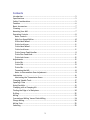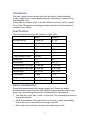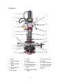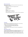
1
The premier source of tooling, parts, and accessories for bench top machinists. Mini Mill User’s Guide from LittleMachineShop.com © Copyright 2006, LittleMachineShop.com All rights reserved. Photos © Copyright 2006, PhotoBoost.com All rights reserved. Written by Chris Wood of LittleMachineShop.com. LittleMachineShop.com http://www.littlemachineshop.com 396 W. Washington Blvd. #500, Pasadena, CA 91103 (800) 981-9663 • Fax (626) 797-7934 2 Contents Introduction ................................................................................. 5 Specifications ............................................................................... 5 Safety Considerations ..................................................................... 5 Features ..................................................................................... 6 Basic Accessories ........................................................................... 7 Cleaning ..................................................................................... 7 Mounting Your Mill ......................................................................... 7 Operating Controls ......................................................................... 8 Motor Controls ........................................................................... 9 High/Low Speed Shifter ...............................................................10 X-Axis Hand Wheel .....................................................................10 X-Axis Lock Lever .......................................................................11 Y-Axis Hand Wheel .....................................................................11 Y-Axis Lock Lever.......................................................................11 Z-Axis Coarse Feed Handles...........................................................11 Z-Axis Fine Feed Knob .................................................................11 Z-Axis Lock Lever .......................................................................12 Adjustments................................................................................12 X-Axis Gib ................................................................................12 Y-Axis Gib ................................................................................13 Z-Axis Gib ................................................................................13 Tramming the Mill ......................................................................14 Motor to Intermediate Gear Adjustment ...........................................15 Lubrication .................................................................................16 Lubricating the Transmission Gears .................................................16 Changing Spindle Tools ...................................................................17 Squaring a Vise ............................................................................18 Using Parallels .............................................................................19 Clamping with a Clamping Kit...........................................................20 Finding the Edge of a Workpiece .......................................................20 Drilling ......................................................................................22 Milling .......................................................................................23 Conventional Milling Versus Climb Milling .............................................24 Plunge Milling ..............................................................................24 Milling Slots ................................................................................25 Surfacing....................................................................................25 3 Common Accessories......................................................................25 End Mills .................................................................................25 Work Holding ............................................................................26 Vises ......................................................................................26 Clamping Kits and Accessories .......................................................27 Setup Tools ..............................................................................28 Maintenance ...............................................................................28 Cleaning..................................................................................28 Motor Brushes ...........................................................................28 4 Introduction This user’s guide covers the mini mills that are sold by Grizzly Industrial, Harbor Freight Tools, Homier Mobile Merchants, Micro-Mark, Cummins Tools, and Wholesale Tool. These mills are made in China, in several different factories, but to a similar set of plans. The general operating principles covered in this document are common to all of them. Specifications The following specifications are common to these mills. Metric Imperial Drilling capacity 13 mm dia ½” dia End mill capacity 16 mm dia 5/8” dia Face mill capacity 30 mm dia 1.2” dia X-axis travel 220 mm 8.7” Y-axis travel 100 mm 3.9” Z-axis (spindle) travel 180 mm 7” Spindle tilt ±45° ±45° Motor power 350 W 0.47 HP Spindle speed Low range 0-1100 rpm 0-1100 rpm Spindle speed High range 0-2500 rpm 0-2500 rpm Spindle taper 3MT or R8 3MT or R8 T-slot width 12 mm 7/16” Weight (net/gross) 50/68 kg 110/150 lb. Package size (L x W x H) 560 x 500 x 740 mm 22 x 19.7 x 29.2” Safety Considerations Always use common sense when using a power tool. Review the safety instructions that came with your mill. Besides the general safety rules for any power tool, the following are specific considerations for the mini mill. • Your mini mill is just that, a mini, or small mill. Don’t attempt jobs that are beyond its capacity. • Check the workpiece after you secure it in the vise or other work holding device. Be sure it is secure before turning on the mill. • Don’t wear loose clothing or jewelry when operating the mill. 5 Features 1 11 2 3 12 4 13 5 6 14 7 15 16 8 9 17 10 18 1. Motor 2. Drawbar (under cap) 3. High/low speed shifter 4. Motor controls 5. Spindle 6. Drill chuck 7. Table 8. Saddle 9. X-axis lock lever 10. Y-axis hand wheel 11. Z-axis fine feed knob 12. Z-axis coarse feed handle 6 13. Z-axis lock lever 14. Column 15. Z-axis travel stop 16. X-axis hand wheel 17. Y-axis lock lever 18. Base Basic Accessories The following accessories come with most mini mills. Some mini mills come with additional accessories. 13 mm (1/2”) drill chuck and appropriate arbor Drawbar Spindle locking pin Two T-slot nuts Oil can Spanner wrench for spindle nut Hex wrenches 3, 4, 5, and 6 mm Open end wrenches 8 x 10 mm, 14 x 17 mm, 17 x 19 mm, and 36 mm. Cleaning Your mill will arrive coated with grease to protect it from corrosion during shipment. Follow this procedure to remove the grease: 1. Wipe most of the grease off with rags or paper towels. 2. Clean the surfaces with mineral spirits (paint thinner). 3. Coat the surfaces with oil. See the “Lubrication” section on page 16 for specific recommendations for lubricants. Mounting Your Mill The mini mill must be bolted down to the workbench because it is top-heavy. It is unsafe to operate the mini mill if it is not bolted to a workbench. Before you mount your mini mill, plan the positioning carefully. If you simply bolt it to the middle of the workbench, you won’t be able to turn the Y-axis hand wheel. Either mount the mini mill at the front edge of the bench so the Y7 axis hand wheel hangs over the edge of the bench, or mount the mini mill on a riser about 1.5” thick to provide room to turn the Y-axis hand wheel. The mounting bolts must extend through the riser and bolt the mill to the bench to keep it from tipping. Be sure that you have room on both sides of the mill for the X-axis travel. The table will move to the right so that the left end of the table is almost flush with the saddle. You need an additional 8” to the right so that you can remove the table off the right side of the mill. The table moves to the left so that the right end of the table is almost flush with the saddle. The following diagram shows the holes required to mount the mill and the clear area around the bolt pattern to allow use and maintenance of the mini mill. Mount the mill to the workbench with 3/8” or 10 mm bolts. The bolts should be about 1” (25 mm) longer than the thickness of the workbench. Use fender washers on the underside of wooden benches to prevent the nuts from pulling through. Operating Controls There are several controls used to operate the mill. Become familiar with them before you use the mill. 8 Motor Controls 1 2 1. Power switch 2. Speed control The power switch latches in the off position when you press the big red button. To turn the switch on, slide the big red button in the direction of the arrow. The big red button will swing up to the on position. The power switch interrupts the input power to the speed control circuit board. You control the motor speed by adjusting a potentiometer that provides the speed setting value to the speed control circuit board. There is a safety switch on the speed control potentiometer that forces you to return the control to minimum speed when starting the mill. Always turn the speed control to the minimum speed position before starting the mill. Starting the mill with the speed control set to a higher speed can damage the speed control circuit board. To power up the mill: 1. Turn the speed control to the minimum speed position. 2. Turn on the power by sliding the red cover of the switch up to release the latch. Always turn the power off when you leave the mill. Leaving the power on can damage the speed control circuit board. To power down the mill: 1. Turn the speed control to the minimum speed position. 2. Turn off the power by latching the red cover of the switch. 9 To start the mill: 1. Ensure that the speed control is set to the minimum speed position. 2. Advance the speed control to the desired speed. To stop the mill: • Turn the speed control to the minimum speed position. High/Low Speed Shifter The high/low speed shifter is on the left side of the spindle housing. It selects the spindle speed range. Low speed range 0-1100 RPM High speed range 0-2500 RPM Never move this lever when the mill is turning. You might need to turn the spindle slightly by hand as you move the high/low speed shifter to engage the gears. X-Axis Hand Wheel The X-axis hand wheel moves the table to the left or right, depending on which way it is turned. Use this hand wheel to position the table. The dial on this handle indicates the relative position of the table. The graduated dial can be repositioned for convenience. Each division of the dial represents a movement of 0.001”. On some mini mills there are 62.5 divisions on the dial. On these mills, each full turn of the hand wheel moves the table 1/16” (0.0625”). Other mini mills have 50 graduations on the dial. On these mills, each full turn of the hand wheel moves the table 0.050”. 10 X-Axis Lock Lever The X-axis lock lever is on the front of the saddle behind the Y-axis hand wheel. Use this lever to lock the X-axis so it does not move inadvertently. Pulling out on the lever and simultaneously turning it can change the locked position of this lever. Pulling out disengages the lever from the locking screw and allows it to move to a different position. You might need to adjust the screw in the base of the lever before you can disengage the lever. Y-Axis Hand Wheel The Y-axis hand wheel moves the table to the front or back, depending on which way it is turned. Use this hand wheel to position the table. The dial on this handle indicates the relative position of the table. The graduated dial can be repositioned for convenience. Each division of the dial represents a movement of 0.001”. On some mini mills there are 62.5 divisions on the dial. On these mills, each full turn of the hand wheel moves the table 1/16” (0.0625”). Other mini mills have 50 graduations on the dial. On these mills, each full turn of the hand wheel moves the table 0.050”. Y-Axis Lock Lever The Y-axis lock lever is on the right side of the saddle behind the X-axis hand wheel. Use this lever to lock the Y-axis so it does not move inadvertently. Pulling out on the lever and simultaneously turning it can change the locked position of this lever. Pulling out disengages the lever from the locking screw and allows it to move to a different position. You might need to adjust the screw in the base of the lever to make this adjustment. Z-Axis Coarse Feed Handles The Z-axis coarse feed handles are on the right side of the spindle housing. The three long handles allow you to quickly lower and raise the head. Use them to position the mill head, and also for drilling. Z-Axis Fine Feed Knob The Z-axis fine feed knob is located on the right front corner of the spindle housing. Use this knob to make find adjustments to the position of the head assembly. There are 60 divisions on the dial. Each full turn of the knob moves the head assembly 0.060”. Each division of the dial represents a movement of 0.001”. To engage the Z-axis fine feed: • Move the hub and coarse feed handles in to engage the dog clutch. You might need to turn the Z-axis fine feed knob to align the dogs. 11 To disengage the Z-axis fine feed: • Move the hub and coarse feed handles out to disengage the dog clutch. You might need to turn the Z-axis fine feed knob to relieve pressure from the dogs. Fine feed disengaged Fine feed engaged Z-Axis Lock Lever The Z-axis lock lever is on the right side of the head assembly behind the Z-axis coarse feed hub. Use this lever to lock the Z-axis so it does not move inadvertently. Pulling out on the lever and simultaneously turning it can change the locked position of this lever. Pulling out disengages the lever from the locking screw and allows it to move to a different position. You might need to adjust the screw in the base of the lever to make this adjustment. Adjustments Keeping your mini mill in adjustment is an on-going process. You should check all the following adjustments when you set up your mill and then periodically as you use your mill. X-Axis Gib A gib is a strip of metal placed between the bearing surface of two machine parts to ensure a precision fit and provide adjustment for wear. The mini mill has gibs in several places, including between the saddle and the table. The X-axis gib provides adjustment for the mating dovetails on the saddle and the table that provide the X-axis (crosswise) motion. To adjust the X-axis gib: 1. Loosen the four lock nuts on the front of the saddle. 2. Slightly loosen all four setscrews on the front of the saddle. 3. Snug each setscrew equally. This will lock the table in position. 12 4. Loosen each setscrew 1/8 turn to allow the table to move. 5. While holding the setscrews from turning, tighten the lock nuts. 6. Test by turning the hand wheel. Loosen or tighten all the setscrews the same amount until the table moves freely, but without play in the dovetail. X-axis gib adjusting screws Y-Axis Gib The Y-axis gib provides adjustment for the mating dovetails on the base and the saddle that provide the Y-axis (in and out) motion. To adjust the Y-axis gib: 1. 2. 3. 4. 5. 6. Loosen the two lock nuts on the right side of the saddle. Slightly loosen both setscrews on the right side of the saddle. Snug each setscrew equally. This will lock the saddle in position. Loosen each setscrew 1/8 turn to allow the saddle to move. While holding the setscrews from turning, tighten the lock nuts. Test by turning the hand wheel. Loosen or tighten both setscrews the same amount until the saddle moves freely, but without play in the dovetail. Z-Axis Gib The Z-axis gib provides adjustment for the mating dovetails on the column and the head assembly that provide the Z-axis (vertical) motion. To adjust the Z-axis gib: 1. 2. 3. 4. 5. 6. Loosen the four lock nuts on the right side of the head assembly. Slightly loosen all four setscrews on the right side of the head assembly. Snug each setscrew equally. This will lock the head assembly in position. Loosen each setscrew 1/8 turn to allow the head assembly to move. While holding the setscrews from turning, tighten the lock nuts. Test by turning the Z-axis coarse feed handles. Loosen or tighten all the setscrews the same amount until the head assembly moves freely, but without play in the dovetail. 13 Tramming the Mill Tramming is the process of squaring the spindle with the table on a mill. This is important on the mini mill because the angle of the head is adjustable from side to side. Because the column is held in position by a clamping mechanism, the angle of the spindle can change without you being aware. Tramming the mill requires the use of a dial indicator, or better, a dial test indicator. The indicator is mounted so that it rotates with the spindle and reads against the table at the farthest distance possible from the spindle. The indicator can be mounted with a test indicator holder, or with a simple shop-made holder. To tram the mill: 1. While supporting the head and column, loosen the large nut at the back of the base of the column. 2. Tighten the nut so that the column can just be moved. 3. Mount the dial indicator or dial test indicator so that it will rest on the front left and front right corners of the table. 14 4. Take readings on the left front and right front corners of the table. Calculate the difference to see how much and which way to move the top of the column. 5. Move the column and take additional readings. Repeat until the readings are the same to within 0.001”. 6. Tighten the large nut at the back of the base of the column. Motor to Intermediate Gear Adjustment A metal gear on the motor drives a plastic gear on the top of the intermediate shaft. If these gears are not meshed properly, they can make a lot of noise. It is easy to adjust the mesh to minimize the noise. To adjust the motor to intermediate gear mesh: 1. Slightly loosen the four socket head cap screws that attach the motor mount. 15 2. 3. 4. 5. Shift the mill into high gear. Turn on the mill to approximately half speed. Move the motor until the gear noise is minimized. Tighten the four socket head cap screws that attach the motor mount. Lubrication We recommend the use of two lubricants on your mill. Where oil is required, we recommend Mobil 1 synthetic motor oil. Mobil 1 far exceeds the lubrication needs of the mini mill, and maintains a good surface film between applications. Any of the available viscosities work fine. Where grease is required, we recommend Lubriplate 630-AA lithium (white) grease. Lithium grease is a plastic-friendly grease that is widely available and easy to use. Before each use, lubricate the following points with Mobil 1 or other suitable oil. • Oil the column dovetail and rack. The following points on your mini mill require lubrication. Location Lubricant Frequency Notes Table and other machined surfaces Mobil 1 motor oil Daily Table dovetails Lithium grease Yearly Table feed screws and nuts Lithium grease Yearly X-axis thrust bearings Mobil 1 motor oil Yearly Transmission gears Lithium grease Yearly Oil lubricates and prevents corrosion See procedure below for lubricating the transmission gears without removing the spindle housing. The spindle and intermediate shaft bearings are deep groove ball bearings that are shielded and do not require additional lubrication. Lubricating the Transmission Gears You can lubricate the transmission gears without removing the spindle housing by using a spray can of lithium grease. To lubricate the transmission gears: 1. Unplug the power cord. 16 2. Remove the cap screw and plastic bushing that limits the upward travel of the Z-axis. 3. Raise the head assembly up the column until the rack disengages from the gear. 4. Manually raise the head assembly until the top of the head assembly is about 1.5" above the top of the column. 5. Use the Z-axis locking lever to lock the head assembly in this position. 6. Insert the lithium grease can’s spray tube into the opening that has been exposed in the back of the head assembly. 7. Spray the grease while rotating the spindle by hand. 8. Shift the high/low shifter to the opposite position. 9. Spray the grease while rotating the spindle by hand. 10. Release the Z-axis locking lever and lower the head assembly until it engages the rack. 11. Continue to lower the head assembly using the Z-axis coarse feed handles. 12. Replace the cap screw and plastic bushing that limits the upward travel of the Z-axis. Changing Spindle Tools The tools you work with are held in the mini lathe spindle by the taper. It is either an R8 taper or 3 Morse taper. Morse taper end mill holder R8 taper end mill holder The tools are held in the spindle by the drawbar. The drawbar is effectively a long bolt that goes down through the spindle and retains the tool. To remove a tool from the spindle: 1. Remove the plastic cap from the top of the spindle. 2. Insert the spindle lock pin the hole in the side of the motor mounting plate. Turn the spindle by hand until the lock pin engages the hole in the spindle. 17 3. Use a wrench to loosen the drawbar about ½ turn. 4. Tap the top of the drawbar with a soft-faced hammer to disengage the taper. 5. Hold the tool with one hand to prevent it from dropping, and unscrew the drawbar. Remove the tool. To install a tool into the spindle: 1. Put the drawbar down through the spindle from the top. 2. Put the tool up into the spindle and thread the drawbar into it. 3. If you have an R8 spindle, rotate the tool until the locking pin engages the slot in the side of the tool. 4. Hold the tool with one hand, and tighten the drawbar with a wrench. Do not use the spindle lock pin to tighten the drawbar, as you will make it too tight. 5. Replace the plastic cap on the top of the spindle. Squaring a Vise When you mount a vise on the mill table, it is important that it be mounted square to the table. If your vise is not square to the table, you will not be able to produce accurate work. The vise is usually mounted with the long axis of the vise perpendicular to the long axis of the table. Thus the jaws are parallel to the X-axis of the mill. To square a vise on the table: 1. 2. 3. 4. Mount the vise on the table and snug, but don’t tighten, the mounting bolts. Open the vise jaws at least 1”. Put the 3/8” diameter post on the top dovetail of a dial test indicator. Put the dial test indicator post in a drill chuck, end mill holder, or collet in the mill’s spindle with the dial facing front. 5. Move the X-, Y-, and Z-axis controls so the point of the dial test indicator is between the vise jaws and about 1/8” below the top of the vise jaws. 18 6. Move the X-axis so the dial test indicator’s point is about 1/16” inside of one end of the vise jaws. 7. Move the Y-axis so that the dial test indicator’s point contacts the fixed jaw of the vise. Continue moving the Y-axis to zero the dial test indicator. 8. Move the X-axis so that the dial test indicator’s point wipes across the width of the fixed jaw of the vise. 9. Take a reading when the point of the dial test indicator reaches the far end of the vise jaw. 10. Move the Z-axis to raise the dial test indicator so that the point is above the vise jaws. 11. Tap the vise with a dead-blow hammer to rotate it in the appropriate direction to reduce the reading on the dial test indicator. 12. Repeat steps 5 through 11 until the reading on the dial test indicator is acceptable to you. You should be able to reduce the reading to 0.001” or less. 13. Tighten the vise mounting bolts. Using Parallels Precision parallels are used to raise the workpiece off the bed of the vise to a position where you can mill the top surface. Parallels come in sets of graduated heights. Choose a pair of parallels that position the top surface of the work above the top of the vise jaws, while keeping enough material between the jaws of the vise for effective clamping. 19 Clamping with a Clamping Kit The clamping kit is the “Erector set” of the milling machine. Use it to clamp large workpieces, fixtures, and even vises to the mill table. Use 1-2-3 blocks as part of your “Erector set”. They can be used to hold workpieces up off the table so you won’t drill into the table. They can be used to mount workpieces, and they can be used to set work up perpendicular to the mill table. When clamping with step blocks and clamp bars, the end of the clamp bar on the step block should be just a little higher than the end on the workpiece. This ensures that the end of the clamp bar makes contact with the workpiece. The stud should be located as close to the workpiece as possible so that the majority of the clamping force is exerted on the workpiece and not the step block. Finding the Edge of a Workpiece Once your work is secured on the table, the next step is to locate the edge of the work so you can zero the X- and Y-axis dials. 20 Most engineering drawings show dimensions from two perpendicular edges of the workpiece. These are the two edges that you should “find,” or locate, as you zero the X- and Y-axis dials. The goal is to set the X- and Y-axis dials to zero with the centerline of the spindle directly over the respective edge of the workpiece. Then all movements of the workpiece relative to the spindle are referenced to these two edges. To find the left edge of a workpiece: 1. Put the solid body of the edge finder in a collet or drill chuck in the mill’s spindle. 2. Offset the movable end of the edge finder so that it is not concentric with the body. 3. Move the edge finder so that it is clear of the workpiece beyond the left edge. 4. Lower the mill’s head so that the smaller diameter section of the movable end of the edge finder is next to the workpiece. 5. Turn the mill on and adjust the speed control to about half of full speed in the low speed range or about one third of full speed in the high speed range. With the edge finder spinning, it is obvious that the movable end of the edge finder is not concentric with the body. 21 6. Slowly turn the X-axis hand wheel clockwise to move the table to the left. As the workpiece approaches the edge finder it first forces the movable end to become more concentric with the body. 7. When the movable end of the edge finder is almost perfectly concentric with the body it will all of a sudden jump to one side and stay there. The point at which the movable end of the edge finder jumps to one side is the point you are looking for. Stop turning the X-axis hand wheel at this point. 8. Turn the motor off. 9. Raise the mill’s head so that the edge finder is completely above the workpiece. 10. Set the X-axis dial to zero. 11. Turn the X-axis hand wheel clockwise 0.100”. If your dials have 62.5 divisions, you turn one full turn plus 37 and one half divisions. If your dials have 50 divisions, you turn two full turns. The movable end of the edge finder is 0.200” in diameter, so you are moving the distance from the center of the edge finder to the edge of the workpiece. 12. Zero the X-axis dial. 13. Note the location of the pointer relative to the X-axis scale across the front of the table. You may want to rotate the pointer so that it aligns with one of the tic marks on the scale. This is the zero point for your X-axis movements. Drilling There are several ways to locate the position at which you want to drill a hole. You can use your layout tools to scribe crossed lines at the hole location, and then use a wiggler to align the mill’s spindle over the intersection of the scribed lines. You can use an edge finder to locate two edges of the workpiece, and then use the X- and Y-axis hand wheels and dials to locate the correct location. Once you find the location, start the hole with a center drill or spotting drill. These specialized drills have relatively large diameter shanks to prevent bending or wobble as you start the hole. This ensures that the hole is located directly below the center of the spindle. Next, drill a pilot hole about 1/8” in diameter (but not larger than the final size you need). Finally, drill to the final drill size you need. You can drill the final hole size as long as two conditions are met. First, the web of the drill bit (the short straight section at the very tip of the drill) must fit into the pilot hole. Second, the drill must not be too large for the mini mill to drive. If power is an issue, use smaller drills to reach the final diameter in steps. 22 Milling You can use collets or end mill holders to hold end mills. The world is split about 50/50 on which is better. We will give you the arguments for both sides and let you decide. Collets End Mill Holders Collets are shorter than end mill holders and so give you more vertical work area. End mill holders are longer than collets and so let you reach nearer the mini mill's table. Collets grip the end mill all the way around and so provide a better grip. End mill holders have a setscrew that bears on the flat on the shank of the end mill and so ensure that the end mill cannot slip. Collets are more concentric than end mill holders because they grip all the way around the end mill's shank. Because they fit the end mill closely end mill holders ensure concentricity. Collets are less expensive than end mill holders and so can be replaced when they wear out. End mill holders are more robust than collets and are less prone to wear out. It's fun juggling an end mill, a collet, and a drawbar all at the same time It is easier to replace an end mill in an end mill holder because the end mill holder can remain in the spindle. Whether you choose end mill holders or collets, they are used to hold an end mill in the spindle of the mini mill. End mills are called that because they cut on the end, as well as on the periphery. Earlier milling cutters used in horizontal milling machines only cut on the periphery. This makes end mills versatile. You can mill the sides of a workpiece, the top surface of a workpiece, and even cut slots and holes in a workpiece. 23 Conventional Milling Versus Climb Milling Climb Milling Conventional Milling Depending on the direction in which you move the workpiece against the end mill you are either climb milling or conventional milling. As shown in the illustration above, you are climb milling when the end mill turns as to climb the slope made by cutting. Climb milling has several advantages, and is often recommended for modern milling machines. The flutes dig in to material with a climbing action, and the workpiece and rotation of the cutter are going in the same direction. With this forward stroke the tooth starts with a full chip and pushes the workpiece down against the table or holding device. This requires less machine power, the cutter does not dull as soon, and a better surface finish is produced. However, climb milling requires a very rigid milling machine with virtually no backlash. Because the workpiece and the milling cutter are moving in the same direction, the milling cutter tends to pull the workpiece away from the driving device if there is any backlash. This can overload the cutter and stall the machine. Or it can simply leave a poor surface finish. On light mills like the mini mill, use conventional milling for all but the lightest cuts. Then, take your final cut of one or two thousandths of an inch using climb milling for the best surface finish. Plunge Milling Plunge milling is the same action as drilling, but using a center cutting end mill instead of a drill bit. This is how you start a slot that does not extend to the edge of the workpiece. Some end mills are center cutting. This means that one of the cutting edges on the end of the end mill extends across the center of the end mill so that there is a cutting edge for the full diameter of the end of the end mill. Non–center cutting end mills have cutting edges on the end, but they do not extend to the center. These end mills will cut on the end and can be used for slotting and surfacing, but you cannot plunge a non–center cutting end mill straight down into the workpiece. 24 Milling Slots Milling slots is the signature operation for a vertical milling machine. For example, to make a belt-adjustment slot, you plunge mill through the workpiece at one end of the slot, mill the length of the slot and raise the end mill at the other end. But of course, life is not as simple as this. You may or may not be able to remove all the material in one pass. If the workpiece is thick you might need to make multiple passes along the length of the slot, lowering the end mill between passes. And, if you use an end mill where the diameter of the end mill is the same as the width of the slot, you are conventional milling on one side of the slot, and climb milling on the other. You will see markedly different surface finishes on the two sides of the slot. But since slots usually need to provide some clearance for the bolt that will go through them, the solution is easy. Use an end mill the same size as the bolt, then take a few cleanup passes to widen the slot slightly wider than the end mill diameter. Your final passes should be climb-milling passes on each side of the slot. Surfacing Surfacing is used to square a workpiece and to provide a good-looking surface as well as to change the size of a workpiece. If you are trying to make a good-looking surface, use as large a diameter cutter as is practical. While a fly cutter can surface a large area in one pass, we do not recommend their use on the mini mill. If the single point tool in the fly cutter catches on the work, it almost guarantees that the mini mill will break a gear. It is prudent to use a smaller diameter cutter, such as an indexable end mill for surfacing. Common Accessories You will soon find that the purchase of a mill is just an initial step. There are many tools and accessories that you will need to get full use from your mill. Following are some common accessories used with the mini mill. End Mills Conventional wisdom is that 2-flute end mills are used on aluminum, while 4flute end mills are used on steel and brass. Take a look at why before you make a choice. 25 Two flute end mills Four flute end mills Two-flute end mills are used on aluminum because aluminum is easy to machine and you can take big cuts. Two-flute end mills provide a lot of room between the flutes for the big chips produced when making heavy cuts. But on a mini mill, you are probably not as concerned about maximizing production, and thus you are not taking the same big cuts that a production shop might. Four-flute end mills can produce a slightly better finish at the same cutting speeds because there are twice as many cutting edges, each taking off half as much material. But again, if you are not trying to maximize production, you can simply slow the feed rate with a 2-flute end mill for the same effect. End mills are also classed as "center cutting" or "non–center cutting." With a center cutting end mill, you can plunge the end mill into the work as you would a drill. This is important if you are cutting a slot that does not extend to the edge of the part. Center cutting end mills are easy to identify. If the flutes meet in the middle of the end of the end mill, it is a center cutting end mill. In some cases, one of the flutes will be longer, reaching right to the center. If the flutes stop short of the center, leaving a space with no flutes in the center, it is a non–center cutting end mill. Virtually all 2-flute end mills are center cutting end mills. Currently, most 4-flute end mills are center cutting. All the end mills that LittleMachineShop.com sells are center cutting end mills. The 6-piece end mill sets we sell are economical starter sets. Because all the end mills in the set have 3/8" shanks, you only need one end mill holder or collet to use the entire set. Work Holding There are two main ways to hold work on a mill's table: with a vise or by clamping the workpiece to the table. In our experience, most work can be held in a vise. But from time to time there is a large or odd-shaped workpiece that must be clamped to the table. Vises There is a range of different types of vises that you can use on a mini mill. 26 Choose a vise that will handle the work you do. You don't need a 3" vise if the parts you make are a half inch long. While you can usually put small parts in a large vise, it is more convenient to use an appropriate-size vise. Vise jaws are often too deep for the work. In general, you want the top of the workpiece to extend above the top of the vise jaws. To fill the gap from the bottom of the workpiece to the "ways" of the vise, you use parallels. Parallels are strips of metal that have been carefully ground so that the top and bottom edges are parallel with very tight tolerances. They usually come in matched pairs. Place one parallel adjacent to each jaw in the vise and place the workpiece so it rests on the parallels. Clamping Kits and Accessories Clamping kits and their accessories, including 1-2-3 blocks, are the "Erector Sets" of work holding. Use the various pieces of the clamping kit as you see fit to hold workpieces to the mini mill's table. In many cases, you need to lift the workpiece off the table, either because the mill spindle won't reach it or because of a projection on the bottom of the workpiece. 1-2-3 blocks are precision ground to be flat and parallel. Use them as spacers to lift the workpiece. You can also use them as an angle plate by bolting a workpiece to the side of the 1-2-3 block and then clamping the 1-2-3 block to the mill table. 27 Setup Tools Once you have your workpiece mounted on the mini mill, you are ready to start cutting metal. Except for one thing: You don't know where the cutting tool is in relation to the workpiece. Edge finders and center finders help you determine the relationship between the cutting tool and the workpiece. Edge finders locate the edge of the workpiece. Center finders locate the center of existing holes. Wigglers locate the intersection of scribed lines on the workpiece. Maintenance Maintenance of the mini mill is simple, but important. Regular maintenance will keep your mini mill working like new for many years. Cleaning The maintenance you perform most often is cleaning. Keeping swarf off of wearing surfaces is the most important thing you can do to prolong the life of your mini lathe. • Use a 1” paintbrush to remove swarf from the machine as you work. • Clean swarf from the mill, from top down after each use. Motor Brushes The motor brushes can be replaced without removing the motor. Follow these steps. 1. Unplug the power cord. 2. Unscrew the motor brush retainers from the sides of the motor. 3. Replace the motor brushes. 4. Replace the motor brush retainers. 28