1
English
EPSO
N DM
-D
Read Series
y
EPSO
N DM
-D Se
ries
Read
y
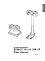
Customer Display
DM-D110-xx2 USB I/F
User’s Manual
404930300
CAUTIONS
❏
This document shall apply only to the product(s) identified herein.
❏
No part of this document may be reproduced, stored in a retrieval system, or transmitted
in any form or by any means, electronic, mechanical, photocopying, recording, or
otherwise, without the prior written permission of Seiko Epson Corporation.
❏
The contents of this document are subject to change without notice. Please contact us for
the latest information.
❏
While every precaution has been taken in the preparation of this document, Seiko Epson
Corporation assumes no responsibility for errors or omissions.
❏
Neither is any liability assumed for damages resulting from the use of the information
contained herein.
❏
Neither Seiko Epson Corporation nor its affiliates shall be liable to the purchaser of this
product or third parties for damages, losses, costs, or expenses incurred by the purchaser
or third parties as a result of: accident, misuse, or abuse of this product or unauthorized
modifications, repairs, or alterations to this product, or (excluding the U.S.) failure to
strictly comply with Seiko Epson Corporation's operating and maintenance instructions.
❏
Seiko Epson Corporation shall not be liable against any damages or problems arising
from the use of any options or any consumable products other than those designated as
Original EPSON Products or EPSON Approved Products by Seiko Epson Corporation.
TRADEMARKS
EPSON® is a registered trademark of Seiko Epson Corporation.
Microsoft®, MS-DOS®, Windows® and Windows NT® are registered trademarks of
Microsoft Corporation.
General Notice: Other product and company names used herein are for identification
purposes only and may be trademarks of their respective companies.
Copyright © 2004 by SEIKO EPSON CORPORATION
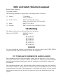
EMC and Safety Standards Applied
Product Name: DM-D110
Type Name: M58DC
The following standards are applied only to the display that is so labeled.
❏
Europe:
CE Marking
Safety: EN60950
❏
North America:
EMI: FCC/ICES-003 Class A
Safety: UL 60950/CSA C22.2 No.60950
❏
Japan:
EMI: VCCI Class A
❏
Oceania:
EMC: AS/NZS 3548 (CISPR22) Class B
CE Marking
The display conforms to the following Directies and Norms
Directive 89/336/EEC
EN55022 Class B
EN55024
IEC 61000-4-2
IEC 61000-4-3
IEC 61000-4-4
IEC 61000-4-5
IEC 61000-4-6
IEC 61000-4-11
WARNING
You are cautioned that changes or modifications not expressly approved by SEIKO EPSON
Corporation could void your authority to operate the equipment.
FCC COMPLIANCE STATEMENT FOR AMERICAN USERS
This equipment has been tested and found to comply with the limits for a Class A digital
device, pursuant to Part 15 of the FCC Rules. These limits are designed to provide reasonable
protection against harmful interference when the equipment is operated in a commercial
environment.
This equipment generates, uses, and can radiate radio frequency energy and, if not installed
and used in accordance with the instruction manual, may cause harmful interference to radio
communications. Operation of this equipment in a residential area is likely to cause harmful
interference in which case the user will be required to correct the interference at his own
expense.
FOR CANADIAN USERS
This Class A digital apparatus complies with Canadian ICES-003.
Cet appareil numérique de la classe A est conforme à la norme NMB-003 du Canada.
English
Important Safety Instructions
This section presents important information intended to ensure safe
and effective use of this product. Read this section carefully, and store
it in an accessible location.
Key to Symbols
The symbols in this manual are identified by their level of importance,
as defined below. Read the following carefully before handling the
product.
WARNING:
Warnings must be followed carefully to avoid serious bodily injury.
CAUTION:
Cautions must be observed to avoid minor injury to yourself or
damage to your equipment.
Note:
Notes have important information and useful tips on the
operation of your equipment.
Safety Precautions
WARNING:
❏
Shut down your equipment immediately if it produces smoke, a
strange odor, or unusual noise. Continued use may lead to fire or
electric shock. Immediately pull out the connection cable to the
computer and contact your DM-D110 dealer or a SEIKO EPSON
service center for advice.
❏
Never attempt to repair this product yourself. Improper repair work
can be dangerous. Tampering with this product may result in injury,
fire, or electric shock.
❏
Do not allow foreign matter to fall into the equipment. Penetration
of foreign objects may lead to fire or shock.
1
❏
If water or other liquid spills into this equipment, immediately pull out
the connection cable to the computer and contact your DM-D110
dealer or a SEIKO EPSON service center for advice. Continued
usage may lead to fire or shock.
CAUTION:
2
❏
Do not plug the cable differently from the instruction in this manual.
Wrong connection may cause equipment damage and fire.
❏
Be sure to set this equipment on a firm, stable, horizontal surface.
Product may be damaged or cause injury if it falls.
❏
Do not use in locations subject to high humidity or dust levels.
Excessive humidity and dust may cause equipment damage, fire, or
shock.
❏
Do not place heavy objects on top of this product. Equipment may
be damaged and cause injury if it falls.
❏
Do not attach more than one extension support. Product may be
damaged or cause injury if it falls.
❏
A stopper limits the horizontal rotation of the display. Do not try to
force it to turn beyond the limits of the stopper. Doing so may
damage the equipment.
❏
When attaching the DM-D110 to an EPSON TM printer, attach it
securely. Also, when the printer has a USB connector, do not
connect the DM-D110 to the USB connection of the TM printer to
avoid exceeding the power capacity.
❏
Wait at least 3 seconds between disconnecting and reconnecting
the USB cable.
❏
Don't connect or disconnect the DM-D110 when the computer is in
the power management state, while it is switching over to the power
management state, or while it is returning from the power
management state.
❏
When using a USB hub, first connect the USB hub to the computer
and then connect the connector of the DM-D110 to the connector
of the USB hub. Set the USB hub to the condition (the self power
mode) which can supply 500 mA electric current to the equipment.
Important Safety Instructions . . . . . . . . . . . . . . . . . . . . . . . . . . . . . . . . . . . . . . . . . .
Key to Symbols . . . . . . . . . . . . . . . . . . . . . . . . . . . . . . . . . . . . . . . . . . . . . . . . . . .
Safety Precautions . . . . . . . . . . . . . . . . . . . . . . . . . . . . . . . . . . . . . . . . . . . . . . . .
Contents . . . . . . . . . . . . . . . . . . . . . . . . . . . . . . . . . . . . . . . . . . . . . . . . . . . . . . . . . . . .
Handling Guidelines . . . . . . . . . . . . . . . . . . . . . . . . . . . . . . . . . . . . . . . . . . . . . . . . . .
Part Names . . . . . . . . . . . . . . . . . . . . . . . . . . . . . . . . . . . . . . . . . . . . . . . . . . . . . .
Unpacking . . . . . . . . . . . . . . . . . . . . . . . . . . . . . . . . . . . . . . . . . . . . . . . . . . . . . . .
Setup . . . . . . . . . . . . . . . . . . . . . . . . . . . . . . . . . . . . . . . . . . . . . . . . . . . . . . . . . . . . . . .
Downloading the driver . . . . . . . . . . . . . . . . . . . . . . . . . . . . . . . . . . . . . . . . . . .
Usage . . . . . . . . . . . . . . . . . . . . . . . . . . . . . . . . . . . . . . . . . . . . . . . . . . . . . . . . . . . . . . .
Cautions on Handling . . . . . . . . . . . . . . . . . . . . . . . . . . . . . . . . . . . . . . . . . . . . .
Attaching to the DM-D stand . . . . . . . . . . . . . . . . . . . . . . . . . . . . . . . . . . . . . . .
Attaching to the TM-H6000II/TM-U675 . . . . . . . . . . . . . . . . . . . . . . . . . . . . .
Attaching to the TM-H5000II/TM-J8000 . . . . . . . . . . . . . . . . . . . . . . . . . . . . .
Attaching to the TM-U375/TM-U950 . . . . . . . . . . . . . . . . . . . . . . . . . . . . . . . .
Attaching to Other TM Printers . . . . . . . . . . . . . . . . . . . . . . . . . . . . . . . . . . . . .
Installing the driver . . . . . . . . . . . . . . . . . . . . . . . . . . . . . . . . . . . . . . . . . . . . . . . . . . .
Installing the driver (Windows XP) . . . . . . . . . . . . . . . . . . . . . . . . . . . . . . . . .
Installing the driver (Windows 2000) . . . . . . . . . . . . . . . . . . . . . . . . . . . .
DIP Switch . . . . . . . . . . . . . . . . . . . . . . . . . . . . . . . . . . . . . . . . . . . . . . . . . . . . . . . . . .
DIP Switch Functions . . . . . . . . . . . . . . . . . . . . . . . . . . . . . . . . . . . . . . . . . . . . .
Operation . . . . . . . . . . . . . . . . . . . . . . . . . . . . . . . . . . . . . . . . . . . . . . . . . . . . . . . . . . .
Turning and tilting the DM-D110 . . . . . . . . . . . . . . . . . . . . . . . . . . . . . . . . . . .
Changing the brightness . . . . . . . . . . . . . . . . . . . . . . . . . . . . . . . . . . . . . . . . . . .
Self Test . . . . . . . . . . . . . . . . . . . . . . . . . . . . . . . . . . . . . . . . . . . . . . . . . . . . . . . . .
Check Items of Self test . . . . . . . . . . . . . . . . . . . . . . . . . . . . . . . . . . . . . . . . . . . .
Performing Self test . . . . . . . . . . . . . . . . . . . . . . . . . . . . . . . . . . . . . . . . . . . . . . .
Diagnostics . . . . . . . . . . . . . . . . . . . . . . . . . . . . . . . . . . . . . . . . . . . . . . . . . . . . . . . . . .
Specifications . . . . . . . . . . . . . . . . . . . . . . . . . . . . . . . . . . . . . . . . . . . . . . . . . . . . . . . .
General Specifications . . . . . . . . . . . . . . . . . . . . . . . . . . . . . . . . . . . . . . . . . . . .
Dimensions . . . . . . . . . . . . . . . . . . . . . . . . . . . . . . . . . . . . . . . . . . . . . . . . . . . . . .
English
Contents
1
1
1
3
4
5
5
6
7
7
8
8
10
15
17
20
23
23
27
32
32
34
34
34
35
35
35
35
36
36
37
3
Handling Guidelines
The DM-D110 is a compact customer display. The DM-D110-xx2 is the
USB I/F specification and can connect with a USB port of a personal
computer.
The characteristics of the DM-D110-xx2 are shown below.
❏ Interface is USB I/F
❏ Supports Window XP and Windows 2000. *1
❏ Design matches EPSON TM printers and IM series.
❏ Possible to set up the “DM-Dstand” or attach the unit to an EPSON
TM printer with any installation option, such as the extension pole.
❏ Dot matrix display with 20 column x 2 lines.
❏ Vacuum fluorescent display provides a wide viewing angle, long
life, high reliability, and high display quality.
❏ Green fluorescent color is easy on the eyes.
❏ Brightness can be adjusted. *2
❏ Control is based on the EPSON ESC/POS standard command set.
❏ Supported by OPOS, APD.
*1 The “USB RS-232 convert driver” is necessary for using the USB I/F.
The driver is not included, so you must download it. (See page 7.)
This driver is Windows XP and Windows 2000 compliant. When
using a USB hub, use a hub of the self-power type (with an AC
adapter). You cannot use a hub of the bus-power type (without an
AC adapter).
*2 The initial setting is the brightest setting, but the brightness can be
adjusted by a command or memory switch. See your dealer for
details.
4
English
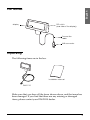
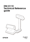
Part Names
DIP switch
(rear side of the display)
display
Connection
cable
USB connector
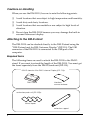
Unpacking
The following items are in the box.
installation manual
DM-D110
Make sure that you have all the items shown above, and that none has
been damaged. If you find that there are any missing or damaged
items, please contact your DM-D110 dealer.
5
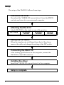
Setup
The setup of the DM-D110 follows these steps.
Download the driver
Download the "USB RS-232 convert driver" from the EPSON
web site and store it in your personal computer.
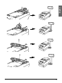
Attaching the DM-D110
Attach DM-D110 to the stand or one of the printers.
s
DM-D Stand
TM-H6000II/
TM-U675
TM-H5000II/
TM-J8000
TM-U375/
TM-U950
Setting the DIP switch
When the transfer rate is different from that of the driver,
remove the cable and change the setting of the DIP switch.
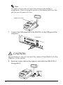
Connecting the DM-D110
After starting up Windows on the computer, connect the
DM-D110 to the USB connector.
Installing the driver
Install the "USB RS-232 convert driver" in the computer.
Setup is complete
6
The “USB RS-232 convert driver” is necessary to use the DM-D110-xx2
USB I/F. This can be obtained from one of the following URLs.
http://www.epson-pos.com/ (Japan, Europe, and other countries not
listed below)
http://pos.epson.com/ (USA/Canada and North America)
Create a folder on the computer and store the downloaded driver.
This driver must be installed to all computers which use USB I/F.
This driver supports Window XP and Windows 2000.
Usage
The DM-D110 can be used with the following equipment.
❏ DM-D stand. You can attach the DM-D110 to the DM-D stand
directly using the “DM-D stand unit for DM Customer Display”
(DP-110). Also, if you want to extend the height of the DM-D110, an
optional extension pole unit (DP-105) is required. (See page 8.)
❏ TM-H6000II/TM-U675. You can attach the DM-D110 to
TM-H6000II/TM-U675 printers using the “DM-D pole unit for TM
printers (Type A)” (DP-502). (See page 10.)
❏ TM-H5000II/TM-J8000 printers. You can attach the DM-D110 to
TM-H5000II/TM-J8000 printers using the “DM-D pole unit for TM
printers (Type B)” (DP-503). (See page 15.)
❏ TM-U375/TM-U950. You can attach the DM-D110 to the TM-U375/
TM-U950 printers using the “DM-D pole unit for TM printers
(Type A)” (DP-502). (See page 17.)
❏ Other TM printers. You can attach the DM-D110 using the “DM-D
pole unit for TM printers (Type A)” (DP-502) and Velcro tapes or
screws. (See page 20.)
7
English
Downloading the driver
Cautions on Handling
When you use the DM-D110, be sure to note the following points:
❏ Avoid locations that are subject to high temperature and humidity.
❏ Avoid dirty and dusty locations.
❏ Avoid locations that are unstable or are subject to high levels of
vibration.
❏ Do not drop the DM-D110 because you may damage the built-in
vacuum fluorescent display.
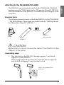
Attaching to the DM-D stand
The DM-D110 can be attached directly to the DM-D stand using the
“DM-D stand unit for DM Customer Display” (DP-110). The USB
connector of the DM-D110 is connected to the USB port of the
computer.
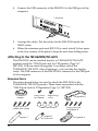
Required items
The following items are used to attach the DM-D110 to the DM-D
stand. If you want to extend the length of the DM-D110. You must get
the items separately from the DM-D stand unit (DP-110).
<DM-D stand unit for DM Customer Display (DP-110)>
DM-D stand
interface
connector base
<extension pole unit (DP-105)>
Velcro tapes
extension support
8
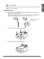
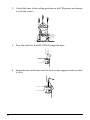
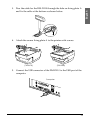
1. Pass the cable for the DM-D110 through the DM-D stand.
When extending the length of the DM-D stand, attach the extension
pole unit(DP-105) to the DM-D stand.
When using the
extension pole unit
(DP-105)
2.
Insert the tab on the DM-D110 (or the extension pole) into the hole
on the DM-D stand until you feel it click.
3. Attach the base plate to the DM-D stand following the number of
the arrow shown below. At this time, push the base plate until it is
locked by the hook on the DM-D stand.
1
2
The plate is locked by
the hook.
9
English
Assembling steps
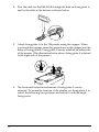
4. Connect the USB connector of the DM-D110 to the USB port of the
computer.
Computer
5. Arrange the cables. Put the cables for the DM-D110 inside the
DM-D stand.
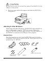
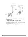
6. When the extension pole unit (DP-105) is used, attach Velcro tapes
to the four corners of the plate to keep the unit from falling down.
Attaching to the TM-H6000II/TM-U675
The DM-D110 can be attached directly to TM-H6000II/TM-U675
printers using the “DM-D pole unit for TM printers (Type A)”
(DP-502). You can attach fixing plate A on either side of the
TM-H6000II/TM-U675. After attaching it, you can slide the display
freely. The USB connector of the DM-D110 is connected to the USB port
of the computer.
Required items
The items shown below are used to attach the DM-D110 to the
TM-H6000II/TM-U675 printers. These items are packed with the
“DM-D pole unit for TM printers (Type A)” (DP-502).
stopper
fixing screws for
rubber feet (small)
support C
10
fixing screw
for stopper
angle fixing
screw
rubber feet (small)
support B
for extension
fixing plate B
fixing screws for
fixing plate B
fixing plate A
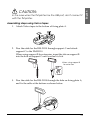
Assembling steps
1. Pass the cable for the DM-D110 through support C, and attach
support C to the DM-D110.
When using support B for extension, insert the tab on support B
into the hole on support C until you feel it click.
When using support B
for extension
2. Attach the rubber feet to the printer.
3. Attach fixing plate B to the printer.
11
English
CAUTION:
Be sure that you do not connect the cable of the DM-D110 to the
USB port of the printer.
4. Pass the cable for the DM-D110 through the hole on fixing plate A,
and fix the cable at the bottom as shown below.
5. Attach fixing plate A to the TM printer using the stopper. When
you attach the stopper, insert the projections on the stopper into the
holes of fixing plate B. Fixing plate A can be attached on either side
of the printer. (The illustration below shows fixing plate A attached
to the right side of the printer.)
6. The horizontal rotation mechanism of fixing plate A can be
adjusted. To secure the location of the display, set fixing plate A to
one of the following four positions and secure it with the angle
fixing screw.
12
13
English
Note:
The paper roll cover may not open if the position of the display is
inappropriate. Before securing the position of the display, make sure that
you can open the paper roll cover.
paper roll cover
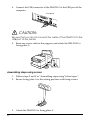
7. Connect the USB connector of the DM-D110 to the USB port of the
computer.
Computer
CAUTION:
Be sure that you do not connect the cable of the DM-D110 to the
USB port of the printer.
8. Store any excess cable in the support, and attach the DM-D110 to
fixing plate A.
14
The DM-D110 can be attached directly to the TM-H5000II/TM-J8000
printers using the “DM-D pole unit for TM printers (Type B)” (DP-503).
The USB connector of the DM-D110 is connected to the USB port of the
computer.
Required items
The following items are used to attach the DM-D110 to the TM-H5000II
/TM-J8000 printers. These items are packed with the “DM-D pole unit
for TM printers (Type B)” (DP-503).
fixing screws
support B
(for extension)
base
support C
CAUTION:
Be sure that you do not connect the cable of the DM-D110 to the
USB port of the printer.
Assembling steps
1. Pass the cable for the DM-D110 through support C and attach
support C to the DM-D110.
When using support B for extension, insert the tab on support B
into the hole on support C until you feel it click.
When using support B for
extension
15
English
Attaching to the TM-H5000II/TM-J8000
2. Attach the base to the setting position on the TM printer and secure
it with the screws.
3. Pass the cable for the DM-D110 through the base.
4. Insert the tab on the base into the hole on the support until you feel
it click.
16
English
5. Connect the USB connector of the DM-D110 to the USB port of the
computer.
Computer
CAUTION:
Be sure that you do not connect the cable of the DM-D110 to the
USB port of the printer.
Attaching to the TM-U375/TM-U950
The DM-D110 can be attached directly to the TM-U375/TM-U950
printers using the “DM-D pole unit for TM printers (Type A)”
(DP-502). The USB connector of the DM-D110 is connected to the USB
port of the computer.
Required items
The following items are used to attach the DM-D110 to the TM-U375/
TM-U950 printers. These items are packed with the “DM-D pole unit
for TM printers (Type A)” (DP-502).
<For TM-U950>
<For TM-U375>
rubber feet
(square)
rubber feet
(large)
fixing screws
fixing screws
for rubber feet for metallic
portion
(large)
rubber feet
(square)
fixing screws
for plastic position
<For TM-U375 and TM-U950>
support C
support B
for extension
fixing plate A
17
CAUTION:
Be sure that you do not connect the cable of the DM-D110 to the
USB port of the printer.
Assembling steps
1. Pass the cable for the DM-D110 through support C and attach
support C to the DM-D110.
When using support B for extension, insert the tab on support B
into the hole on support C until you feel it click.
When using support B
for extension
2. Attach the rubber feet to the printer.
[TM-U375]
18
[TM-U950]
4. Attach the secure fixing plate A to the printer with screws.
[TM-U375]
[TM-U950]
5. Connect the USB connector of the DM-D110 to the USB port of the
computer.
Computer
19
English
3. Pass the cable for the DM-D110 through the hole on fixing plate A
and fix the cable at the bottom as shown below.
CAUTION:
Be sure that you do not connect the cable of the DM-D110 to the
USB port of the printer.
6. Store any excess cable in the support, and attach the DM-D110 to
fixing plate A.
Attaching to Other TM Printers
When using with other TM printers, the DM-D110 can be attached to a
desk or other surface, using the “DM-D pole unit for TM printers
(Type A)” (DP-502), and Velcro tapes or screws. The USB connector of
the DM-D110 is connected to the USB port of the computer.
Required items
The following items are used when the DM-D110 is used with other
TM printers. These items are packed with the “DM-D pole unit for TM
printers (Type A)” (DP-502).
Velcro tapes
Velcro tapes
fixing plate A
support B (for extension)
fixing screws for
wood position
20
support C
In the case when the TM printer has the USB port, don't connect it
with the TM printer.
Assembling steps using Velcro tapes
1. Attach Velcro tapes to the bottom of fixing plate A.
2. Pass the cable for the DM-D110 through support C and attach
support C to the DM-D110.
When using support B for extension, insert the tab on support B
into the hole on support C until you feel it click.
When using support B
for extension
3. Pass the cable for the DM-D110 through the hole on fixing plate A,
and fix the cable at the bottom as shown below.
21
English
CAUTION:
4. Connect the USB connector of the DM-D110 to the USB port of the
computer.
Computer
CAUTION:
Be sure that you do not connect the cable of the DM-D110 to the
USB port of the printer.
5. Store any excess cable in the support, and attach the DM-D110 to
fixing plate A.
Assembling steps using screws
1. Follow steps 2 and 3 in “Assembling steps using Velcro tapes.”
2. Secure fixing plate A to the setting position with fixing screws.
3. Attach the DM-D110 to fixing plate A.
22
The “USB RS-232 convert driver” is necessary to use the DM-D110-xx2
USB I/F. This driver is composed of “USB high Speed Serial
Converter” and “USB Serial Port.” Both of them must be installed.
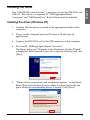
Installing the driver (Windows XP)
1. Confirm that the driver is stored in the appropriate folder of the
computer.
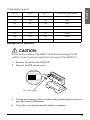
2. Power on the computer and start Windows XP and quit all
applications.
3. Connect the DM-D110-xx2 to the USB connector of the computer.
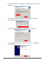
4. First install “USB high Speed Serial Converter”.
The Setup starts and “Welcome to the Hardware Update Wizard”
is displayed. Select [Install from a list or specific location] and click
[Next].
5. “Please choose your search and installation options.“ is displayed.
Select [Search for the best driver in these locations] and enter the
place where the downloading driver is stored. Click [Next].
23
English
Installing the driver
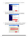
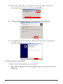
6. “Completing the Found New Hardware Wizard“ is displayed.
Click [Finish].
7. Next install “USB Serial Port”.
“Welcome to the Found New Hardware Wizard“ is displayed.
Choose [Install from a list of specific location] and click [Next].
8. “Please choose your search and installation options.“ is displayed.
Select [Search for the best driver in these locations] and enter the
place where the downloading driver is stored. Click [Next].
24
English
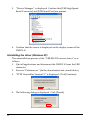
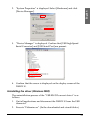
9. “Completing the Found New Hardware Wizard“ is displayed.
Click [Finish].
Confirmation of the operation
Confirm that the installation was normal.
1. Select [Control Panel] from the Start menu; then double click
[System]. On the Hardware tab, click {Device Manager].
2. “System properties” is displayed. Select [Hardware] and click
[Device Manager].
25
3. “Device Manager” is displayed. Confirm that [USB high Speed
Serial Converter] and [USB Serial Port] are present.
4. Confirm that the cursor is displayed on the display screen of the
DM-D110.
Uninstalling the driver (Windows XP)
The uninstallation process of the “USB RS-232 convert driver” is as
follows.
1. Quit all applications and disconnect the DM-D110 from the USB
connector.
2. Execute “Ftdiunin.exe.” (In the downloaded and stored folder.)
3. “FTDI Uninstaller Version2.1” is displayed. Click [Continue].
4. The following dialog is displayed. Click [Finish].
26
English
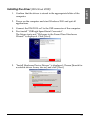
Installing the driver (Windows 2000)
1. Confirm that the driver is stored in the appropriate folder of the
computer.
2. Power on the computer and start Windows 2000 and quit all
applications.
3. Connect the DM-D110-xx2 to the USB connector of the computer.
4. First install “USB high Speed Serial Converter”.
The Setup starts and “Welcome to the Found New Hardware
Wizard” is displayed. Click [Next].
5. “Install Hardware Device Drivers“ is displayed. Choose [Search for
a suitable driver for my device] and click [Next].
27
6. “Locate Driver Files“ is displayed. Select [Specify a location] and
click [Next].
7. The following dialog is displayed. Enter the place where the
downloaded driver is stored and click [OK].
8. “Driver Files Search Results“ is displayed. Click [Next].
9. “Completing the Found New Hardware Wizard” is displayed.
Click [Finish].
28
English
10. Next install “USB Serial Port”.
The Setup starts and “Welcome to the Found New Hardware
Wizard” is displayed. Click [Next].
11. “Install Hardware Device Drivers“ is displayed. [Search for a
suitable driver for my device] and click [Next].
12. “Locate Driver Files“ is displayed. Select [Specify a location] and
click [Next].
29
13. The following dialog is displayed. Enter the place where the
downloading driver is stored and click [OK].
14. “Driver Files Search Results“ is displayed. Click [Next].
15. “Completing the Found New Hardware Wizard” is displayed.
Click [Finish].
Confirming the operation
Confirm that the installation was normal.
1. Select [Settings]-[Control Panel]-[System] from the Start menu of
Windows.
30
English
2. “System Properties“ is displayed. Select [Hardware] and click
[Device Manager].
3. “Device Manager” is displayed. Confirm that [USB high Speed
Serial Converter] and [USB Serial Port] are present.
4. Confirm that the cursor is displayed on the display screen of the
DM-D110.
Uninstalling the driver (Windows 2000)
The uninstallation process of the “USB RS-232 convert driver” is as
follows.
1. Quit all applications and disconnect the DM-D110 from the USB
connector.
2. Execute “Ftdiunin.exe”. (In the downloaded and stored folder.)
31
3. “FTDI Uninstaller Version2.1” is displayed. Click [Continue].
4. The following dialog is displayed. Click [Finish].
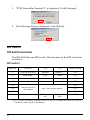
DIP Switch
DIP Switch Functions
The DM-D110 has one DIP switch. The functions of the DIP switch are
as follows:
DIP switch 1
DSW1 No.
Function
ON
OFF
Default setting
1-1
Data receive error
Ignored
Displays “?”
OFF
1-2
Data length
7 bits
8 bits
OFF
1-3
Parity on or off
Parity
No parity
OFF
1-4
Parity type
Even
Odd
OFF
ON
1-5
1-6
Change transmission speed
See “Transmission speed.”
1-7
1-8
OFF
ON
Self test selection (*)
Perform self
test
Do not perform
OFF
(*)This function can select whether or not the self test is performed when you turn on
the power. See “Self Test” for details.
32
SW1-5
SW1-6
SW1-7
Transmission speed (bps)
ON
ON
ON
2400
OFF
ON
ON
4800
ON
OFF
ON
9600
OFF
OFF
ON
19200
ON
ON
OFF
38400
OFF
ON
OFF
57600
ON
OFF
OFF
115200
OFF
OFF
OFF
reserved
English
Transmission speed
Setting the DIP switches
CAUTION:
Remove the cable of the DM-D110 before removing the DIP
switch cover to prevent electrical damage to the DM-D110.
1. Remove the cable of the DM-D110.
2. Remove the DIP switch cover.
ON
1
2
3 4
5
6
7 8
DIP switch cover
3. Change each setting of the switches with a pointed object, such as a
pen tip or small screwdriver.
4. Close the cover and connect the cable to computer.
33
Operation
There is no power switch on the DM-D110-xx2. Connect the USB
connector to the computer or start the computer to which the
DM-D110-xx2 is connected.
When the power is on, the cursor appears on the display.
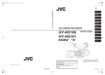
Turning and tilting the DM-D110
You can turn or tilt the display while holding the support. The display
can be moved easily, so do not move any further if it stops. If you move
it by force, you may damage it.
With the “DM-D pole unit for TM printers (Type B)” (DP-503), the
display area may not face the direction you desire. In this case, remove
the base, change the position of the tab of the base so that the display
faces to the direction you desire, and reattach it to the base.
45° for left
(you can turn the same angle to the right.)
48°
45°
The display area has the following range of movement:
❏ Tilt: 48° max. (4 steps, 5 positions)
❏ Horizontal rotation: 90° max.
330° max.
Attached to the DP-110
Attached to the pole unit
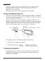
Changing the brightness
The brightness is set in the maximum at the factory shipment. The
brightness can be adjusted by a command or memory switch. For
details, ask your dealer.
34
The DM-D110 has a self test function. If you want to perform a self test,
you must change the setting of the DIP switch.
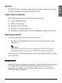
Check Items of Self test
The following items are checked during the self test:
❏ Control ROM version
❏ DIP switch settings
❏ Memory switch settings
❏ Example of display characters
❏ Example of each function, such as brightness, flashing, and scroll
Performing Self test
To perform the self test, follow the steps below.
1. Set SW 1-8 of the DIP switch to ON, and connect the cable to the
computer.
Note:
If the contents of the self test are not displayed, the DM-D110 may be
malfunctioning. Please contact your DM-D110 dealer for assistance.
When the self test is finished and no error occurs, the DM-D110 is ready
to receive data.
Diagnostics
The DM-D110 has a diagnostics function. When the DM-D110 is turned
on, diagnostics, such as an internal memory test, are carried out
regardless of the DIP switch settings. When an error is detected, an
error message is displayed.
35
English
Self Test
Specifications
General Specifications
Vacuum
fluorescent
display
Character
Specifications
Number of characters
40 (20 columns x 2 lines)
Display color
Green (505 nm)
Brightness
690 ( cd/m2)
Type of
character
Character grid
Alphanumeric
characters
95
International
characters
37
Extended graphics
128 characters x 12 pages
Font
5 x 7 dot matrix, cursor
Character size
3.5mm x 5.0mm
Character pitch
5.2mm
Tilt angle
Horizontal
rotation
Max 48°
(4 steps, 5 positions)
When DP-110 is attached
Max 90° (for each left and
right at 45°)
When the pole unit is attached
Max 330°
USB 2.0
full-speed mode
Interface
Electrical
Specifications
Environmental
Specifications
Reliability
Specification
36
Rated voltage
DC +5 V
Rated current
0.35 A (max)
Operation environment
Temperature : 5 °C to 40°C
Humidity: 30% to 85%
(No condensation)
Storage environment
Temperature : -10°C to 50°C
Humidity: 30% to 90%
(No condensation)
MTBF (vacuum fluorescent display
only)
20,000 hours
(When the brightness is
reduced to half)
English
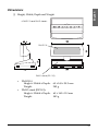
Dimensions
❏ Height, Width, Depth and Weight
<DM-D110 and DM-D stand>
DM-D110
DM-D stand (DP-110)
•
•
DM-D110:
Height x Width x Depth:
Weight:
69 x 165 x 50.5 mm
285 g
DM-D stand (DP-501):
Height x Width x Depth:
Weight:
63 x 165 x 110 mm
385 g
37
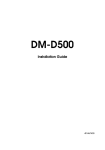
<DM-D pole units>
DM-D pole unit for
TM printers (Type A)
(DP-502)
DM-D pole unit for
TM printer (Type B)
(DP-503)
248 mm
260 mm
164 mm
78 mm
50 mm
base
53 mm
38
•
Base and support C of the “DM-D pole unit for TM printers
(Type B)” (DP-503):
Height x Width x Depth: 248 x 50 x 53 mm
Weight:
116 g
•
Fixing plate A and support C of the “DM-D pole unit for TM
printers (Type A)” (DP-502):
Height x Width x Depth: 260 x 78 x 164 mm
Weight:
264 g