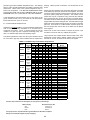
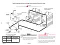
1
TM
Built tough with maximum efficiency
MODELS DB/DW-720-1810
NATURAL GAS-FIRED COMMERCIAL CROSS FLOW COPPER BOILERS
FOR HYDRONIC HEATING AND HOT WATER SUPPLY
WITH ELECTRONIC INTERMITTENT PILOT IGNITION AND
INSTALLATIONS
• INSTALLATION • OPERATION • MAINTENANCE • LIMITED WARRANTY
WARNING: If the information in this manual
is not followed exactly, a fire or explosion may
result causing property damage, personal
injury or loss of life.
— Do not store or use gasoline or other
flammable vapors and liquids in the
vicinity of this or any other appliance.
— WHAT TO DO IF YOU SMELL GAS
· Do not try to light any appliance.
· Do not touch any electrical switch;
·
·
do not use any phone in your
building.
Immediately call your gas supplier
from a neighbor’s phone. Follow
the gas supplier’s instructions.
If you cannot reach your gas
supplier, call the fire department.
— Installation and service must be
performed by a qualified installer,
service agency or the gas supplier.
CAUTION
TEXT PRINTED OR OUTLINED IN RED CONTAINS
INFORMATION RELATIVE TO YOUR SAFETY. PLEASE
READ THOROUGHLY BEFORE INSTALLING AND
USING THIS APPLIANCE.
A DIVISION OF A.O.SMITH CORPORATION
EL PASO, TX McBEE, SC RENTON, WA
STRATFORD, ONTARIO
VELDHOVEN, THE NETHERLANDS
www.hotwater.com
PLACE THESE INSTRUCTIONS ADJACENT TO BOILER AND
NOTIFY OWNER TO KEEP FOR FUTURE REFERENCE.
PRINTED IN U.S.A. 2221 0302
1
PART NO. 211680-000 REV. 00
SUPERSEDES PART NO. 200311-000 REV. 4 & 210265-000 REV. 0
CONTENTS
Page
Page
FOREWORD ................................................................................
REPLACEMENT PARTS ..............................................................
ROUGH-IN DIMENSIONS/CAPACITIES ......................................
Installation Clearances ..............................................................
Levelling ...................................................................................
FEATURES ...................................................................................
Safety Relief Valves ..................................................................
Electronic Intermittent PIlot Ignition Control ..............................
Manual Reset High Temperature Safety Limit Control ...............
Automatic Reset High Temperature Control ..............................
Thermal Balancer .....................................................................
Safety Flow Switch ...................................................................
INSTALLATION INSTRUCTIONS .................................................
Required Ability ........................................................................
Location ...................................................................................
Air Requirements .....................................................................
Venting the Boiler .....................................................................
Gas Connections ......................................................................
Purging ....................................................................................
High Altitude Installations .........................................................
Wiring Connections ..................................................................
Servicing Wiring And/Or Control ..............................................
SYSTEM EQUIPMENT INSTALLATION .......................................
Water Supply Line ....................................................................
Expansion Tank ........................................................................
Vent Valves ..............................................................................
System Headers ......................................................................
Cooling Piping ..........................................................................
Safety Flow Switch ...................................................................
Circulating Pump ......................................................................
2
2-3
3-4
3
3
5
5
5
5
6
6
6
7
7
7
7-8
8-9
9
10-11
11
11-12
12
12
12
12
12
12
12
12-13
13-14
FOREWORD
CAUTION
TEXT PRINTED OR OUTLINED IN RED CONTAINS
INFORMATION RELATIVE TO YOUR SAFETY. PLEASE READ
THOROUGHLY BEFORE USING APPLIANCE.
Low Water Cutoff .....................................................................
Tank Temperature Control ........................................................
SYSTEM INSTALLATION .............................................................
Conventional Space Heating Installation ...................................
Installation As Boiler Replacement ............................................
Linear-Temp Space Heating Applications ..................................
Linear-Temp Space Heating Installations ..................................
Wiring and Schematic Diagrams ..............................................
HOT WATER SUPPLY APPLICATIONS .......................................
Water Line Connections ...........................................................
Hard Water Conditions .............................................................
START-UP AND OPERATING INSTRUCTIONS ..........................
LIGHTING AND OPERATING INSTRUCTIONS ...........................
Internal Contaminants ..............................................................
Precautions ..............................................................................
Checking and Adjusting the Input .............................................
Pilot Burner ..............................................................................
Main Burner .............................................................................
PRE-TROUBLESHOOTING .........................................................
TROUBLESHOOTING ..................................................................
GENERAL MAINTENANCE ..........................................................
Relief Valve ..............................................................................
Venting Maintenance ................................................................
Heat Exchanger Preventive Maintenance ..................................
Deliming ...................................................................................
Deliming Solvents .....................................................................
Removing Light Deposits of Scale ............................................
Removal of an Existing Boiler From A Common Venting
System ................................................................................
LIMITED WARRANTY ..................................................................
14
14
14
14-15
15-17
17
17-20
21-26
27-32
27
27
32
33
34
34
34
34
34-35
35
35-38
39
39
39
39
39-40
40
40
40
41
These manuals can be purchased from the CSA International,
8501 East Pleasant Valley Road, Cleveland, OH 44131 or 178
Rexdale Boulevard, Toronto, Ontario Canada, M9W 1R3.
REPLACEMENT PARTS
CHECK THE DIAGRAMS THOROUGHLY BEFORE STARTING
INSTALLATION TO AVOID POSSIBLE ERRORS AND TO
MINIMIZE TIME AND MATERIALS COST.
Replacement parts may be ordered through A. O. Smith dealers,
authorized servicers or distributors. Refer to the Yellow Pages for
where to call or contact (in United States) the A.O. Smith Water
Products Company, 5621 West 115th Street, Alsip, IL 60803,
1-800-433-2545 or (in Canada) A.O. Smith Enterprises Ltd., 768
Erie Street, Stratford, Ontario, Canada N5A 6T3, 800-265-8520.
When ordering parts be sure to state the quantity, part number and
description of the item including the complete model and serial
number as it appears on the product. Refer to the parts lists for
more information.
This design complies with the latest edition of the ANSI Z21.13
CSA 4.9 low-pressure boiler.
For Technical Assistance call A.O. Smith Technical Information
Center at 1-800-527-1953.
Particular attention should be given to the installation of
thermometers at the locations indicated in the diagrams as these
are necessary for checking the operation of the boiler.
WARNING
THE INLET/OUTLET WATER MANIFOLD ON YOUR A. O. SMITH
UNIT INCORPORATES AN “O RING" WATER SEAL ASSEMBLY.
THE MANIFOLD IS NOT DESIGNED TO SUPPORT THE WEIGHT
OF THE WATER PIPING SYSTEM. AS ON ALL BOILER
INSTALLATIONS, SPECIAL CARE MUST BE TAKEN TO ENSURE
PROPER SUPPORT.
Detailed installation diagrams are in this manual. These diagrams
will serve to provide the installer with a reference for the materials
and method of piping suggested. IT IS NECESSARY THAT ALL
WATER AND GAS PIPING AND THE ELECTRICAL WIRING BE
INSTALLED AND CONNECTED AS SHOWN IN THE DIAGRAMS.
MAKE SURE THE GAS ON WHICH THE BOILER WILL OPERATE
IS THE SAME AS THAT SPECIFIED ON THE UNIT RATING PLATE.
The boiler installation must conform to these instructions and the
requirements of the local authority having jurisdiction.
Where required by the authority having jurisdiction, the installation
must conform to the Standard for Controls and Safety Devices for
Automatically Fired Boilers, ANSI/ASME CSD-1.
In the absence of local code requirements, the boiler installation
must conform to the most current National Fuel Gas Code, ANSI
Z223.1 and/or CAN/CSA-B149.1-00 installation codes.
WARNING
UNDER NO CIRCUMSTANCES SHOULD THE EQUIPMENT
ROOM WHERE THE BOILER IS INSTALLED EVER BE UNDER
NEGATIVE PRESSURE. PARTICULAR CARE MUST BE TAKEN
WHEN EXHAUST FANS, COMPRESSORS, AIR HANDLING
EQUIPMENT, ETC., MAY INTERFERE WITH THE COMBUSTION
AND VENTILATION AIR SUPPLIES OF THIS BOILER.
2
CAUTION
Label all wires prior to disconnection when servicing controls. Wiring
errors can cause improper and dangerous operation.
"Verify proper operation after servicing."
ROUGH-IN DIMENSIONS/
CAPACITIES
Two inch clearance is allowable from combustible construction for
hot water pipes.
Sufficient clearance should be provided at one end of the boiler to
permit access to heat exchanger tubes for cleaning. Maximum
operating water supply pressure 160 psi. Gas supply pressure:
13.8" w.c. max., 5.5" w.c. min.
Sufficient area should be provided at the front and sides of the unit
for proper servicing. Clearances of 48" in front and 24" on sides is
recommended. In a utility room installation, the door shall be wide
enough to allow the boiler to enter or to permit the replacement of
another appliance.
INSTALLATION CLEARANCES
These boilers are approved for installation on combustible flooring
in an alcove with minimum clearance to combustibles See chart
below.
LEVELLING
Each unit should be checked after installation to be certain that it is
level.
WARNING
AN AMPLE SUPPLY OF AIR MUST BE PROVIDED
FOR PROPER COMBUSTION AND VENTILATION.
TABLE 1, ROUGH-IN DIMENSIONS
Models
DW-720
DW-840
DW-960
DW-1080
DW-1210
DW-1350
DW-1480
DW-1610
DW-1810
Dimensions inches
mm
inches
mm
inches
mm
inches
mm
inches
mm
inches
mm
inches
mm
inches
mm
inches
mm
A
46 1/2
1181
52 1/5
1326
57 3/4
1467
52 7/8
1343
58 1/2
1486
64 1/2
1638
69 1/2
1765
75
1905
82 1/2
2096
B
29 5/8
752
29 5/8
752
29 5/8
752
32 3/4
832
32 3/4
832
32 3/4
832
34
864
34
864
34
864
C
54 3/4
1391
54 3/4
1391
54 3/4
1391
58
1473
58
1473
58
1473
60 1/2
1537
60 1/2
1537
60 1/2
1537
D
1 1/4 NPT
1 1/4 NPT
1 1/4 NPT
1 1/4 NPT
1 1/2 NPT
1 1/2 NPT
1 1/2 NPT
2
NPT
2
NPT
E
7 3/4
197
7 3/4
197
7 3/4
197
7 1/2
191
7 1/2
191
7 1/2
191
7 1/2
191
7 1/2
191
7 1/2
191
F
15 1/2
394
15 1/2
394
15 1/2
394
18 1/2
470
18 1/2
470
18 1/2
470
18 1/2
470
18 1/2
470
18 1/2
470
G
17 1/4
438 17 1/4
438 17 1/4
438 18 9/16 471 18 9/16
471 18 9/16
471
19 1/8
486 19 1/8
486
19 1/8
486
H
4 1/4
108
4 1/4
108
4 1/4
108
4
102
4
102
4
102
4 1/2
114
4 1/2
114
4 1/2
114
J
2 NPT
2 NPT
2 NPT
2 1/2 NPT
2 1/2 NPT
2 1/2 NPT
2 1/2 NPT
2 1/2 NPT
2 1/2 NPT
K
2 NPT
2 NPT
2 NPT
2 1/2 NPT
2 1/2 NPT
2 1/2 NPT
2 1/2 NPT
2 1/2 NPT
2 1/2 NPT
L
1 NPT
1 NPT
1 NPT
1 1/4 NPT
1 1/4 NPT
1 1/4 NPT
1 1/4 NPT
1 1/4 NPT
1 1/4 NPT
M
12
305
14
356
14
356
16
406
16
406
18
457
18
457
18
457
20
508
N
15 1/2
394
16 1/2
419
16 1/2
419
17 1/4
438
17 1/4
438
17 1/4
438
13 3/4
349
13 3/4
349
13 3/4
349
W
32 1/8
816
31 1/8
791
32 1/8
816 30 15/16 786 30 15/16
786 30 15/16
786
31
787
31
787
31
787
Approx.
Shipping 780 lbs 354 Kg. 950 lbs 431 Kg 950 lbs 431 Kg 1000 lbs 454 Kg 1075 lbs 488 Kg. 1100 lbs 499 Kg 1125 lbs 510 Kg 1150 lbs 522 Kg 1250 lbs 567 Kg
Weight.
All Models
Minimum Clearances To Combustibles
Water
Blank
Top
Side
Side
Rear
12" (305mm) 18" (457mm) 6" (155mm) 6" (155mm)
3
Vent
6" (155mm)
Front
Alcove
WARNING
Your Dura-Max boiler is not designed to operate with a boiler inlet water temperature of less than
100°F (38°C). Colder inlet water temperatures will result in significant condensation developing on
the heat exchanger. This situation can cause a corrosive environment for the heat exchanger,
burners and venting resulting in premature damage, which could result in serious personal injury or
death.
For systems that use large volumes of cold water or system utilizing heavy water draws (Cer-Temp),
condensation can be prevented by using a by-pass loop. See page 16.
TABLE 2, PRESSURE DROP
Model
DW-720
DW-840
DW-960
DW-1080
DW-1210
DW-1350
DW-1480
DW-1610
DW-1810
Temp Rise
F
C
20 11.1
30 16.7
40 22.2
20 11.1
30 16.7
40 22.2
20 11.1
30 16.7
40 22.2
20 11.1
30 16.7
40 22.2
20 11.1
30 16.7
40 22.2
20 11.1
30 16.7
40 22.2
20 11.1
30 16.7
40 22.2
20 11.1
30 16.7
40 22.2
20 11.1
30 16.7
40 22.2
Flow Rate
GPM LPM
59 223
39 149
29 111
69 260
46 173
34 130
79 297
52 198
39 149
89 339
60 226
45 169
100 379
67 253
50 190
112 423
75 282
56 212
120 453
80 302
60 226
130 492
87 328
65 246
146 554
98 369
73 277
HdLoss*
M
ft
3.5 1.1
1.7 0.5
1.0 0.3
4.8 1.5
2.1 0.6
1.5 0.5
6.8 2.1
3.3 1.0
1.9 0.6
4.5 1.4
2.1 0.6
1.4 0.4
5.3 1.6
2.7 0.8
1.6 0.5
6.8 2.1
3.2 1.0
1.8 0.5
7.9 2.4
3.9 1.2
2.1 0.6
9.5 2.9
5.0 1.5
3.0 0.9
12.0 3.7
6.2 1.9
3.9 1.2
TABLE 3, RECOVERY CAPACITIES
MODEL
DB/DW-720
DB/DW-840
DB/DW-960
DB/DW-1080
DB/DW-1210
DB/DW-1350
DB/DW-1480
DB/DW-1610
DB/DW-1810
INPUT
BTUH
KW
720,000
211
840,000
246
960,000
281
1,080,000
316
1,210,000
354
1,350,000
395
1,480,000
433
1,610,000
472
1,810,000
530
F
C
GPH
LPH
GPH
LPH
GPH
LPH
GPH
LPH
GPH
LPH
GPH
LPH
GPH
LPH
GPH
LPH
GPH
LPH
20F
11.1C
3,535
13,379
4,124
15,609
4,713
17,839
5,367
20,317
6,013
22,762
6,709
25,396
7,176
27,162
7,806
29,548
8,776
33,219
30F
16.6C
2,356
8,920
2,749
10,406
3,142
11,893
3,578
13,545
4,009
15,175
4,473
16,931
4,784
18,108
5,204
19,699
5,851
22,146
U.S. Gallons/Hr and Litres/Hr at TEMPERATURE RISE INDICATED
36F
40F
50F
54F
60F
70F
72F
80F
90F
100F
20C 22.2C 27.7C 30C 33.3C 38.8C 40C 44.4C 50C 55.5C
1,964 1,767 1,414 1,309 1,178 1,010
982
884
785
707
7,433 6,690 5,352 4,955 4,460 3,823 3,716 3,345 2,973 2,676
2,291 2,062 1,649 1,527 1,375 1,178 1,145 1,031
916
825
8,672 7,805 6,244 5,781 5,203 4,460 4,336 3,902 3,469 3,122
2,618 2,356 1,885 1,745 1,571 1,346 1,309 1,178 1,047
943
9,911 8,920 7,136 6,607 5,946 5,097 4,955 4,460 3,964 3,568
2,982 2,684 2,147 1,988 1,789 1,534 1,491 1,342 1,193 1,073
11,287 10,158 8,127 7,525 6,772 5,805 5,644 5,079 4,515 4,063
3,341 3,007 2,405 2,227 2,004 1,718 1,670 1,503 1,336 1,203
12,646 11,381 9,105 8,430 7,587 6,504 6,323 5,691 5,058 4,552
3,727 3,355 2,684 2,485 2,236 1,917 1,864 1,677 1,491 1,342
14,109 12,698 10,158 9,406 8,465 7,256 7,054 6,349 5,644 5,079
3,987 3,588 2,870 2,658 2,392 2,050 1,993 1,794 1,595 1,435
15,090 13,581 10,865 10,060 9,054 7,761 7,545 6,791 6,036 5,432
4,337 3,903 3,122 2,891 2,602 2,230 2,168 1,952 1,735 1,561
16,416 14,774 11,819 10,944 9,849 8,442 8,208 7,387 6,566 5,910
4,875 4,388 3,510 3,250 2,925 2,507 2,438 2,194 1,950 1,755
18,455 16,609 13,288 12,303 11,073 9,491 9,227 8,305 7,382 6,644
4
108F 110F 120F
60C 61.1C 66.6C
655
643
589
2,478 2,433 2,230
764
750
687
2,891 2,838 2,602
873
857
785
3,304 3,243 2,973
994
976
895
3,762 3,694 3,386
1,114 1,093 1,002
4,215 4,139 3,794
1,242 1,220 1,118
4,703 4,617 4,233
1,329 1,305 1,196
5,030 4,939 4,527
1,446 1,419 1,301
5,472 5,372 4,925
1,625 1,596 1,463
6,152 6,040 5,536
126F 130F 140F
70C 72.2C 77.7C
561
544
505
2,124 2,058 1,911
655
634
589
2,478 2,401 2,230
748
725
673
2,832 2,744 2,548
852
826
767
3,225 3,126 2,902
954
925
859
3,613 3,502 3,252
1,065 1,032
958
4,031 3,907 3,628
1,139 1,104 1,025
4,311 4,179 3,880
1,239 1,201 1,115
4,690 4,546 4,221
1,393 1,350 1,254
5,273 5,111 4,746
and pilot gases are cut off during the “OFF” cycle. Pilot gas ignition
is proven by the pilot sensor. Main burner ignition will not occur if
the pilot sensor does not first sense pilot ignition.
FEATURES
IMPORTANT
Only qualified personnel shall perform the initial firing of the heater.
At this time the user should not hesitate to ask the individual any
questions regarding the operation and maintenance of the unit.
Lighting and Operating instructions are included at the rear of this
manual. By using this checklist the user may be able to make
minor operational adjustments and save unnecessary service calls.
However, the user should not attempt repairs which are not listed
under the USER column.
SAFETY RELIEF VALVES
Your local code authority may have other specific relief valve
requirements not covered below.
FIGURE 2
WARNING
THE PURPOSE OF A SAFETY RELIEF VALVE IS TO AVOID
EXCESSIVE PRESSURE WHICH MAY CAUSE TANK
EXPLOSION, SYSTEM OR BOILER DAMAGE.
On natural gas models the igniter control continues to operate
(creating a spark) until the pilot burner is ignited or the ignition
system shuts down. Shut down occurs automatically if the pilot
burner does not ignite within 15 seconds. The unit then waits for
(5) minutes and retries ignition (standard models).
TO AVOID WATER DAMAGE A DRAIN LINE MUST BE
CONNECTED TO A SAFETY RELIEF VALVE TO DIRECT
DISCHARGE TO A SAFE LOCATION. A DRAIN LINE MUST NOT
BE REDUCED FROM THE SIZE OF THE VALVE OUTLET AND IT
MUST NOT CONTAIN ANY VALVES BETWEEN THE BOILER AND
THE RELIEF VALVE OR THE RELIEF VALVE AND THE DRAIN
EXIT. IN ADDITION, THERE SHOULD NOT BE ANY
RESTRICTIONS IN A DRAIN LINE NOR SHOULD IT BE ROUTED
THROUGH AREAS WHERE FREEZING CONDITIONS MIGHT
OCCUR. DO NOT THREAD OR CAP THE DRAIN LINE EXIT.
RESTRICTING OR BLOCKING A DRAIN LINE WILL DEFEAT THE
PURPOSE OF THE RELIEF VALVE AND MAY CREATE AN
UNSAFE CONDITION. INSTALL A DRAIN LINE WITH A
DOWNWARD SLOPE SUCH THAT IT NATURALLY DRAINS
ITSELF.
The electronic intermittent pilot ignition control and the 100% lockout
control are non-adjustable devices.
(See troubleshooting steps on page 40). If pilot is not lit and sensed
within the flame establishing timing for each module, the appliance
will shut down.
If any safety relief valve is replaced, the replacement valve must
comply with the latest version of the ASME Boiler and Pressure
Vessel Code, Section IV (“HEATING BOILERS”). Select a relief
valve with a discharge rating NOT less than the boiler input, and a
set pressure NOT exceeding the working pressure of any component
in the system.
An ASME rated temperature and pressure relief valve must be
installed on each and every water storage tank in a hot water supply
system.
The storage tank temperature and pressure relief valve must comply
with the applicable construction provisions of the Standard for Relief
Valves and Automatic Gas Shutoff Devices for Hot Water Supply
Systems, ANSI Z21 or CAN/CSA-B149.1 (latest edition). The valve
must be of the automatic reset type and not embody a single-use
type fusible plug, cartridge or linkage.
ELECTRONIC INTERMITTENT PILOT
IGNITION CONTROL
ALL MODELS - The solid state ignition control, fig. 2, ignites the
pilot burner gas by creating a spark at the pilot assembly. Pilot gas
is ignited and burns during each running cycle. The main burner
5
MANUAL RESET HIGH TEMPERATURE
SAFETY LIMIT CONTROL
This device senses water temperature in the boiler. When water
temperature exceeds dial setting, power to main gas valve is
interrupted and the boiler is shut down.
HOT WATER SUPPLY - Manual reset - factory set at 210°F (100°C).
Water temperature must drop at least 20°F (11°C) before reset is
possible.
HYDRONIC HEATING - Manual reset - factory set at 250°F (121°C).
Water temperature must drop at least 20°F (11°C) before reset is
possible.
Single stage and modulating units use a combined control as shown
in fig. 4.
Dual stage models are equipped with a limit like one shown in
figure 3.
AUTOMATIC RESET
HIGH TEMPERATURE LIMIT CONTROL
The heater operation with above set points will be as follows:
1)
When heater temperature rises to LO thermostat setting the
main gas valve will close its second stage operator to drop
input to approximately 50% of total input.
2)
System conditions will determine if temperature rise at LO
thermostat sensor location will continue to rise until shut-off
by high limit or drop causing heater to go back to full input.
CAUTION
LIMIT CONTROLS ARE NOT TO BE USED AS THERMOSTATS.
ALL MODELS - This limit is a safety device wired in series with the
ignition system. Set the limit control dial to a minimum of 10°F
(6°C) above the maximum designed system temperature. If the
boiler outlet water temperature should exceed the high limit setting,
the main gas valves will close but the circulator will continue to
operate. Maximum adjustable setting is 240°F (116°C) for boilers
and 200°F (93°C) for hot water supply heaters. The differential is
adjustable from 5°F (3°C) to 45°F.
Other system design temperatures will require resetting of the dial.
Total span of temperatures (HI dial cut-off point to LO dial cut-on
point) should not be less than temperature drop of the system.
MODULATING MODELS ONLY
These boilers are factory equipped with a modulating gas valve
that automatically controls the outlet water temperature by
modulating or proportioning the rate of gas thus maintaining a
desired constant outlet water temperature regardless of varying
flow rates.
SINGLE STAGE AND MODULATING MODELS - Are equipped with
the limit like the one shown in fig. 4.
Gas valves either close or open to full gas input, depending upon
heat requirement.
Set temperature controller for desired outlet water temperature.
(fig. 6).
Adjust the set point for the desired operating temperature by turning
the set point adjusting screw on the front of the case until the desired
value is reached on the set point indicating dial. The set point is
calibrated to be at the center of the proportioning range, (see the
manufacturers instructions for complete information on testing and
calibrating this control.)
THERMAL BALANCER
This device serves as a pump shutdown delay switch to balance
the boiler water temperature to system temperature before the pump
stops. Overshooting of boiler temperature is prevented and stack
loss after shutdown is minimized.
DUAL STAGE MODELS ONLY - HIGH/LOW OPERATOR
These boilers are factory equipped with a (combination) temperature
controller to provide high and low firing rates for smooth operation.
(fig. 5).
The temperature dials should be adjusted to have the HI dial set as
a limit to be 10°F (6°C) above desired boiler temperature. These
boilers are shipped with the HI dial set to 200°F (93°C) with a 15°F
(8°C) differential, the LO dial set to 160°F (71°C) with a 10°F (6°C)
differential.
SAFETY FLOW SWITCH
The safety flow switch is a safety device which must be installed at
the water outlet of the unit to prevent main burner operation in the
event of inadequate water flow through the boiler.
This switch may be mounted in a horizontal pipe line or a vertical
pipe line with upward water flow. Do not install the switch where
the water flow is downward.
6
If the boiler is installed above the level of heating system terminal
units, a low water cutoff device must be installed in the boiler outlet
at the time of installation.
INSTALLATION INSTRUCTIONS
REQUIRED ABILITY
INSTALLATION OR SERVICE OF THIS BOILER REQUIRES
ABILITY EQUIVALENT TO THAT OF A LICENSED TRADESMAN
IN THE FIELD INVOLVED. PLUMBING, AIR SUPPLY, VENTING,
GAS SUPPLY AND ELECTRICAL WORK ARE REQUIRED.
WARNING
THE INLET/OUTLET WATER MANIFOLD ON YOUR A. O. SMITH
UNIT INCORPORATES AN "O RING" WATER SEAL ASSEMBLY.
THE MANIFOLD IS NOT DESIGNED TO SUPPORT THE WEIGHT
OF THE WATER PIPING SYSTEM. AS ON ALL BOILER
INSTALLATIONS, SPECIAL CARE MUST BE TAKEN TO ENSURE
PROPER SUPPORT.
LOCATION
When installing the boiler, consideration must be given to proper
location. Location selected should be as close to the stack or
chimney as practical with adequate air supply and as centralized
with the piping system as possible. This location should also be
such that the gas ignition system components are protected from
water (dripping, spraying, etc.) during appliance operation and
service [circulator replacement, control replacement, etc.].
THE BOILER MUST NOT BE INSTALLED ON CARPETING.
THE BOILER SHOULD NOT BE LOCATED IN AN AREA WHERE
IT WILL BE SUBJECT TO FREEZING.
LOCATE IT NEAR A FLOOR DRAIN. THE BOILER SHOULD BE
LOCATED IN AN AREA WHERE LEAKAGE FROM THE BOILER
OR CONNECTIONS WILL NOT RESULT IN DAMAGE TO THE
ADJACENT AREA OR TO LOWER FLOORS OF THE
STRUCTURE.
For installation locations with elevations above 2,000 feet (610 M),
refer to the HIGH ALTITUDE INSTALLATIONS section of this
manual for input reduction procedure.
CHEMICAL VAPOR CORROSION
Heat exchanger corrosion and component failure can be caused
by the heating and breakdown of airborne chemical vapors. Spray
can propellants, cleaning solvents, refrigerator and air conditioning
refrigerants, swimming pool chemicals, calcium and sodium
chloride, waxes, and process chemicals are typical compounds
which are corrosive. These materials are corrosive at very low
concentration levels with little or no odor to reveal their presence.
Products of this sort should not be stored near the boiler. Also, air
which is brought in contact with the water boiler should not contain
any of these chemicals. If necessary, uncontaminated air should
be obtained from remote or outside sources.
AIR REQUIREMENTS
WARNING
FOR SAFE OPERATION, AN AMPLE SUPPLY OF AIR MUST BE
PROVIDED FOR PROPER COMBUSTION AND VENTILATION
IN ACCORDANCE WITH SECTION 5.3, AIR FOR COMBUSTION
AND VENTILATION, OF THE NATIONAL FUEL GAS CODE, ANSI
Z223.1 OR 7.2, 7.3 OR 7.4 OF CAN/CSA B149.1-00,
INSTALLATION CODES, OR APPLICABLE PROVISIONS OF THE
LOCAL BUILDING CODES. AN INSUFFICIENT SUPPLY OF AIR
MAY RESULT IN A YELLOW, LUMINOUS BURNER FLAME,
CARBONING OR SOOTING OF THE FINNED HEAT
EXCHANGER, OR CREATE A RISK OF ASPHYXIATION. DO NOT
OBSTRUCT THE FLOW OF COMBUSTION AND VENTILATION
AIR.
WHEN SUCH LOCATIONS CANNOT BE AVOIDED, A SUITABLE
DRAIN PAN SHOULD BE INSTALLED UNDER THE BOILER. Such
pans should be fabricated with sides at least 2-1/2" (64 mm) deep,
with length and width at least 2" (51 mm) greater than the
dimensions of the boiler and must be piped to an adequate drain.
UNCONFINED SPACE
The pan must not restrict combustion air flow.
If the unconfined space is within a building of tight construction
(buildings using the following construction; weather stripping, heavy
insulation, caulking, vapor barrier, etc.), air for combustion,
ventilation, and draft hood dilution must be obtained from outdoors
or spaces freely communicating with the outdoors. The installation
instructions for confined spaces in tightly constructed buildings must
be followed to ensure adequate air supply.
WARNING
THERE IS A RISK IN USING FUEL BURNING APPLIANCES IN
ROOMS OR AREAS WHERE GASOLINE, OTHER FLAMMABLE
LIQUIDS OR ENGINE DRIVEN EQUIPMENT OR VEHICLES ARE
STORED, OPERATED OR REPAIRED. FLAMMABLE VAPORS
ARE HEAVY AND TRAVEL ALONG THE FLOOR AND MAY BE
IGNITED BY THE IGNITER OR MAIN BURNER FLAMES
CAUSING FIRE OR EXPLOSION. SOME LOCAL CODES PERMIT
OPERATION OF GAS APPLIANCES IF INSTALLED 18 INCHES
OR MORE ABOVE THE FLOOR. THIS MAY REDUCE THE RISK
IF LOCATION IN SUCH AN AREA CANNOT BE AVOIDED.
FLAMMABLE ITEMS, PRESSURIZED CONTAINERS OR ANY
OTHER POTENTIAL FIRE HAZARDOUS ARTICLES MUST
NEVER BE PLACED ON OR ADJACENT TO THE BOILER.
OPEN CONTAINERS OF FLAMMABLE MATERIAL SHOULD NOT
BE STORED OR USED IN THE SAME ROOM WITH THE BOILER.
7
In buildings of conventional frame, brick or stone construction,
unconfined spaces may provide adequate air for combustion, and
draft hood dilution.
CONFINED SPACE
(a) U. S. INSTALLATIONS
When drawing combustion and dilution air from inside a
conventionally constructed building to a confined space, such a
space shall be provided with two permanent openings, ONE IN OR
WITHIN 12 INCHES (30 CM) OF THE ENCLOSURE TOP AND
ONE IN OR WITHIN 12 INCHES (30 CM) OF THE ENCLOSURE
BOTTOM. Each opening shall have a free area of at least one
square inch per 1000 Btuh (2,208 mm2of per kw) of the total input
of all appliances in the enclosure, but not less than 100 square
inches (645 cm2).
If the confined space is within a building of tight construction, air for
combustion, ventilation, and draft hood dilution must be obtained
from outdoors. When directly communicating with the outdoors or
communicating with the outdoors through vertical ducts, two
permanent openings, located in the aforementioned manner, shall
be provided. Each opening shall have a free area of not less than
one square inch per 4000 Btu/hr (551 mm2 per kw) of the total
input of all appliances in the enclosure. If horizontal ducts are
used, each opening shall have a free area of not less than one
square inch per 2000 Btu/hr (1101 mm2 per kw) of the total input of
all appliances in the enclosure.
(B) CANADIAN INSTALLATIONS
Ventilation of the space occupied by the boiler(s) shall be provided
by an opening for ventilation air at the highest practical point
communicating with outdoors. The total cross- sectional area shall
be at least 10% of the area of the combustion air opening but in no
case shall the cross-sectional area be less than 10 square inches
(6500 mm²).
1.
DRAFT HOOD
The integral draft hood, louvers or cabinetry must not be altered.
Provision must be made if the boiler is installed in confined space
or a small boiler room to accommodate draft hood spillage and
avoid risks described above. The upper air opening called for in
the AIR REQUIREMENTS section of this manual is for this purpose.
2.
VENT CONNECTION
The minimum distance from adjacent public walkways, adjacent
buildings, openable windows and building openings shall not be
less than those values specified in the National Fuel Gas Code,
ANSI Z223.1 and/or CAN/CSA B149.1-00, Installation Codes:
Stack or chimney must be a minimum height of 12" (305 mm)
above the annual snow fall to prevent blockage.
Building materials must not come in contact with combustion
products from stack or chimney, due to the degrading properties of
flue products.
In addition to the above, there shall be permanent air supply
opening(s) having a cross-sectional area of not less than 1 square
inch per 7,000 BTUH (315 mm²/kw) up to and including 1,000,000
BTUH plus 1 square inch per 14,000 BTU (158 mm2/kw) in excess
of 1,000,000 BTUH. This opening(s) shall be located at, or ducted
to, a point neither more than 18" (450 mm) nor less than 6 inches
(150 mm) above the floor level.
Materials may be protected from flue products by use of metal or
copper sheeting.
Where power vented equipment is used in the same room as the
boiler, sufficient air openings must be supplied.
The Canadian B149.1-00, Installation Code specifies a 6 foot
horizontal vent terminal clearance to gas and electric meters and
relief devices (this clearance is specified as 4 feet in the U.S. under
the National Fuel Gas Code, ANSI/Z223.1). Therefore instruction
provision 1.34.1-b19(d), which specifies compliance with the 4 foot
clearance, as applies in the U.S. only, and the B149.1-00 Installation
Code applies in Canada.
UNDERSIZED OPENINGS MAY RESULT IN INSUFFICIENT AIR
FOR COMBUSTION.
Where an exhaust fan is installed in the same room with a boiler,
sufficient openings for air must be provided in the walls.
UNDERSIZED OPENINGS WILL CAUSE AIR TO BE DRAWN
INTO THE ROOM THROUGH THE CHIMNEY, CAUSING POOR
COMBUSTION. SOOTING MAY RESULT WITH AN INCREASED
RISK OF ASPHYXIATION.
VENTING THE BOILER
WARNING
THE INSTRUCTIONS IN THIS SECTION ON VENTING THE
BOILER MUST BE FOLLOWED TO AVOID CHOKED
COMBUSTION OR RECIRCULATION OF FLUE GASES. SUCH
CONDITIONS CAUSE SOOTING OR RISKS OF FIRE AND
ASPHYXIATION.
SINGLE WALL OR TYPE B VENTING MAY BE USED WITH
THESE BOILERS. ALL LOCAL UTILITY, STATE/ PROVINCIAL,
REGULATIONS ON VENTING MUST BE FOLLOWED.
VENT SIZING, INSTALLATION AND TERMINATION SHALL BE
IN ACCORDANCE WITH PART 7, VENTING OF EQUIPMENT,
OF THE NATIONAL FUEL GAS CODE, ANSI Z223.1, OR SECTION
7, VENTING SYSTEMS AND AIR SUPPLY FOR APPLIANCES,
OF THE CAN/CSA B149, INSTALLATION CODES, OR
APPLICABLE PROVISIONS OF THE LOCAL BUILDING CODES.
Flue products must have a minimum clearance of 4 feet (1.22 m)
horizontally from, and in no case above or below, unless a 4-foot
(1.22 m) horizontal distance is maintained, from electric meters,
gas meters, regulators and relief equipment.
Vent connections must be made to an adequate stack or chimney
and shall be in accordance with Part 7, Venting of Equipment, of
the National Fuel Gas Code, ANSI Z223.1, or Section 7, Venting
Systems and Air Supply for Appliances, of the CAN/CSA-B149.100, Installation Codes, or applicable provisions of the local building
codes. Size and install proper size vent pipe. Do not reduce pipe
size to less than that of the draft hood outlet unless permitted by
local code.
Horizontal runs of vent pipe shall be securely supported by
adequately placed (approximately every 4 feet [1.2 m]),
noncombustible hangers suitable for the weight and design of the
materials employed to prevent sagging and to maintain a minimum
upward slope of 1/4" per foot (21mm/m) from the boiler to the vent
terminals. Dampers or other obstructions must not be installed in
the vent. Be sure that the vent connector does not extend beyond
the inside wall of the chimney.
Where a continuous or intermittent back draft is found to exist the
cause must be determined and corrected. A special vent cap may
be required. If the back draft cannot be corrected by the normal
methods or if a suitable draft cannot be obtained, a blower type
flue gas exhauster may be employed to ensure proper venting and
correct combustion (where permitted by local code). Contact your
A. O. Smith dealer for power vent instructions.
8
WARNING
FAILURE TO CORRECT BACK DRAFTS MAY CAUSE AIR
CONTAMINATION AND UNSAFE CONDITIONS.
Vent connectors serving appliances vented by natural draft shall
not be connected into any portion of mechanical draft systems
operating under positive pressure.
3.
CONNECTING BOILER TO A COMMON VENT
Do not connect the boiler to a common vent or chimney with solid
fuel burning equipment. This practice is prohibited by most local
building codes as is the practice of venting gas fired equipment to
the duct work of ventilation systems.
Where a separate vent connection is not available and the vent
pipe from the boiler must be connected to a common vent with an
oil burning furnace, the vent pipe should enter the common vent or
chimney at a point ABOVE the flue pipe from the oil furnace.
UL/ULC listed doublewall type B-1 gas vents, through 24" (610
mm) diameter, can be installed in heated and unheated areas and
can pass through floors, ceilings, partitions, walls and roofs,
provided the required clearance is observed.
At the time of removal of an existing boiler, the following steps
shall be performed with each appliance remaining connected to
the common venting system. Perform these steps while the other
appliances remaining connected to the common venting system
are not in operation.
—
Seal any unused openings in the common venting system.
—
Visually inspect the venting system for proper size and
horizontal pitch and determine there is not blockage or
restriction, leakage, corrosion and other deficiencies which
could cause an unsafe condition.
—
Insofar as is practical, close all building doors and windows
and all doors between the space in which the appliances
remaining connected to the common venting system are
located and other spaces of the building. Turn on clothes dryers
and any appliance not connected to the common venting
system. Turn on any exhaust fans, such as range hoods and
bathroom exhaust fans, so they will operate at maximum speed.
Close fireplace dampers.
—
—
—
Place in operation the appliance being inspected. Follow the
lighting instructions. Adjust thermostat so appliance will
operate continuously.
Test for spillage at the draft hood relief opening after five
minutes of main burner operation. Use the flame of a match
or candle, or smoke from a cigarette, cigar or pipe.
After it has been determined that each appliance remaining
connected to the common venting system properly vents when
tested as outlined above, return doors, windows, exhaust fans,
fireplace dampers and any other gas burning appliance to their
previous conditions of use.
9
GAS CONNECTIONS
WARNING
THIS BOILER IS NOT INTENDED TO OPERATE AT GAS SUPPLY
PRESSURE OTHER THAN SHOWN ON THE RATING PLATE.
EXPOSURE TO HIGHER GAS SUPPLY PRESSURE MAY CAUSE
DAMAGE TO GAS VALVES WHICH CAN RESULT IN FIRE OR
EXPLOSION. IF OVERPRESSURE HAS OCCURRED SUCH AS
THROUGH IMPROPER TESTING OF GAS LINES OR
EMERGENCY MALFUNCTION OF THE SUPPLY SYSTEM, THE
GAS VALVES MUST BE CHECKED FOR SAFE OPERATION.
MAKE SURE THAT THE OUTSIDE VENTS ON THE SUPPLY
REGULATORS AND THE SAFETY VENT VALVES ARE
PROTECTED AGAINST BLOCKAGE. THESE ARE PARTS OF
THE GAS SUPPLY SYSTEM, NOT THE BOILER. VENT
BLOCKAGE MAY OCCUR DURING ICE BUILD-UP OR SNOW
STORMS.
WHEN LOCAL CODES REQUIRE A MAIN MANUAL SHUTOFF
VALVE OUTSIDE THE BOILER JACKET, A SUITABLE MAIN
MANUAL SHUTOFF VALVE MUST BE INSTALLED IN A
LOCATION COMPLYING WITH THOSE CODES.
IT IS IMPORTANT TO GUARD AGAINST GAS VALVE FOULING
FROM CONTAMINANTS IN THE GAS WAYS. SUCH FOULING
MAY CAUSE IMPROPER OPERATION, FIRE OR EXPLOSION.
IF COPPER SUPPLY LINES ARE USED THEY MUST BE
APPROVED FOR GAS SERVICE.
BEFORE ATTACHING THE GAS LINE BE SURE THAT ALL GAS
PIPE IS CLEAN ON THE INSIDE.
TO TRAP ANY DIRT OR FOREIGN MATERIAL IN THE GAS
SUPPLY LINE, A DIRT LEG (SOMETIMES CALLED DRIP LEG
OR SEDIMENT TRAP) UPSTREAM OF THE GAS CONTROLS,
MUST BE INCORPORATED IN THE PIPING. The dirt leg must be
readily accessible and not subject to freezing conditions. INSTALL
IN ACCORDANCE WITH RECOMMENDATIONS OF SERVING
GAS SUPPLIERS. REFER TO NATIONAL FUEL GAS CODE, ANSI
Z223.1 AND/OR CAN/CSA-B149.1-00.
To prevent damage, care must be taken not to apply too much
torque when attaching gas supply pipe to gas valve gas inlet.
Fittings and unions in the gas line must be metal to metal type.
Apply joint compounds (pipe dope) sparingly and only to the male
threads of pipe joints. Do not apply compound to the first two
threads. Use compounds resistant to the action of liquefied
petroleum gases.
The boiler and its individual shutoff valve must be disconnected
from the gas supply piping system during any pressure testing of
that system at test pressures in excess of 1/2 psi (3.5 kPa).
The boiler must be isolated from the gas supply piping system by
closing its individual manual shutoff valve during any pressure
testing of the gas supply piping systems at test pressures equal to
or less than 1/2 psi (3.5 kPa).
The boiler and its gas connection must be leak tested before placing
the boiler in operation.
Provisions for vent, bleed and gas relief lines (when applicable).
PURGING
Gas line purging is required with new piping or systems in which
air has entered.
CAUTION
PURGING SHOULD BE PERFORMED BY PERSONS
EXPERIENCED IN THIS TYPE OF GAS SERVICE TO AVOID RISK
OF FIRE OR EXPLOSION. PURGE DISCHARGE MUST NOT
ENTER CONFINED AREAS OR SPACES WHERE IGNITION CAN
OCCUR. THE AREA MUST BE WELL VENTILATED AND ALL
SOURCES OF IGNITION MUST BE INACTIVATED OR REMOVED.
BEFORE PLACING THE BOILER IN OPERATION, CHECK FOR
GAS LEAKAGE. Use soap and water solution or other material
acceptable for the purpose in locating gas leaks. DO NOT USE
MATCHES, CANDLES, FLAME OR OTHER SOURCES OF
IGNITION FOR THIS PURPOSE.
1.
CORRECT GAS
Make sure the gas on which the boiler will operate is the same as
that specified on the boiler rating plate. Do not install the boiler if
equipped for a different type gas, consult your gas supplier. These
boilers are designed to operate on natural gas only.
2A. SIZING GAS SUPPLY LINE (For single boiler installations
and for installations of multiples of two or three of same size
boilers).
Use table 1, which is taken from ANSI booklet Z223.1, NATIONAL
FUEL GAS CODE, and/or CAN/CSA-B149.1-00 to size iron pipe
or equivalent gas supply line. Table 4 is based on a pressure drop
of 0.3 inches of water and a specific gravity of 0.60 which is
approximately for natural gas. (LP gas has an S.G. of about 1.53).
If the service pressure is five inches water column or less, use one
pipe size larger than specified in table 1 in order to minimize pressure
drop in the line.
2B. SIZING GAS SUPPLY LINE (For multiples of over three boilers
of same size or for multiple installations of two or more mixed
sizes).
Capacities in cubic feet per hour of 0.60 specific gravity gas for
different sizes and lengths are shown in table 4. No additional
allowance is necessary for an ordinary number of fittings.
Where it is necessary to use more than the average number of
pipe fittings i.e. elbows, tees, and valves in gas supply line, use a
pipe larger than specified to compensate for increased pressure
drop.
TABLE 4
MAXIMUM CAPACITY OF PIPE IN CUBIC FEET OF GAS PER HOUR (BASED UPON A PRESSURE DROP OF
0.3 INCH WATER COLUMN AND 0.6 SPECIFIC GRAVITY GAS)
Length in Feet (Meters)
Nominal Iron Pipe Size, Inches (NPT)
From Gas Meter
1/2
3/4
1
1 1/4
1 1/2
2
2 1/2
10 (3)
132
278
520
1,050
1,600
3,050
4,800
20 (6)
92
190
350
730
1,100
2,100
3,300
30 (9)
73
152
285
590
890
1,650
2,700
40 (12)
63
130
245
500
760
1,450
2,300
50 (15)
56
115
215
440
670
1,270
2,000
60 (18)
50
105
195
400
610
1,150
1,850
70 (21)
46
96
180
370
560
1,050
1,700
80 (24)
43
90
170
350
530
990
1,600
90 (27)
40
84
160
320
490
930
1,500
100 (30)
38
79
150
305
460
870
1,400
125 (38)
34
72
130
275
410
780
1,250
150 (46)
31
64
120
250
380
710
1,130
175 (53)
28
59
110
225
350
650
1,050
200 (61)
26
55
100
210
320
610
980
*The heating value of natural gas is approximately 1050 Btu/ft³.
Propane (L.P.) gas has a heating value of approximately 2500 Btu/ft³.
TABLE 5
Multipliers To Be Used With Table 1 When Applying The
Gravity Factor To Other Than .60 Specific Gravity
Specific
Gravity
.35
.40
.45
.50
.55
*.60 (Nat.)
.65
.70
.75
.80
.85
.90
Multiplier
1.31
1.23
1.16
1.10
1.04
1.00
.96
.93
.90
.87
.84
.82
Gravity
1.00
1.10
1.20
1.30
1.40
*1.50 (Prop.)
1.60
1.70
1.80
1.90
*2.00 (Butane)
2.10
Specific
Multiplier
.78
.74
.71
.68
.66
.63
.61
.59
.58
.56
.55
.54
*Use these correction factors if exact specific gravity of the gas is not known.
10
3
8,500
5,900
4,700
4,100
3,600
3,250
3,000
2,800
2,600
2,500
2,200
2,000
1,850
1,700
4
17,500
12,000
9,700
8,300
7,400
6,800
6,200
5,800
5,400
5,100
4,500
4,100
3,800
3,500
Applications of the gravity factor converts the figures given in table
1 to capacities with another gas of different specific gravity. Such
application is accomplished by multiplying the capacities given in
table 1 by the multipliers shown in table 5.
HIGH ALTITUDE INSTALLATIONS
IN CANADA
To determine the size of each section of gas piping in a system
within the range of table 4 proceed as follows:
Acceptance of these models for use at altitudes above 2000 feet
(610 m) is based on field test of the individual installation by the
provincial/state authority having jurisdiction.
•
IN THE U.S.A.
Determine the gas demand of each appliance to be attached to
the piping system. When table 4 is to be used to select the
piping size, calculate the gas demand in terms of cubic feet per
hour for each piping system outlet. The gas demand for an
appliance can be found by dividing its heat input rate by the
gas’s heating value.
•
Obtain or determine the length of piping from the gas meter or
service regulator to the appliance(s).
•
In table 1, select the row showing the distance to the most remote
outlet or the next longer distance if the table does not give the
exact length. This is the only distance used in determining the
size of any section of gas piping. If the gravity factor is to be
applied, the values in the selected row of table 4 are multiplied
by the appropriate multiplier from table 5.
•
Total the gas demands of all appliances on the piping system.
Enter table 4, on the left hand side, at the row equal to or just
exceeding the distance to the most remote outlet. Select the
pipe size in the row with a capacity equal to or just exceeding
the total gas demand. This is the required main gas supply line
size leading away from the gas meter or regulator. To determine
the pipe size required for each branch outlet leading away from
the main supply line, determine the gas demand for that outlet.
Enter table 4 on the same row, and select the branch pipe size
for a capacity equal to or just exceeding the demand at that
outlet. The main line can be resized for a lesser capacity after
each branch outlet, since the gas demand is reduced. Total the
gas demands of all remaining appliances branching off
downstream on the main gas line. Re-enter table 4 in the same
row and select the appropriate pipe size with adequate capacity.
Repeat the branch sizing and main line re-sizing for any
remaining appliances in the system.
WARNING
INSTALLATIONS ABOVE 2000 FEET REQUIRE REPLACEMENT
OF THE BURNER ORIFICES IN ACCORDANCE WITH SECTION
8.1.2 OF THE NATIONAL FUEL GAS CODE (ANSI Z223.1).
FAILURE TO REPLACE THE ORIFICES WILL RESULT IN
IMPROPER AND INEFFICIENT OPERATION OF THE APPLIANCE
RESULTING IN THE PRODUCTION OF INCREASED LEVELS OF
CARBON MONOXIDE GAS IN EXCESS OF SAFE LIMITS WHICH
COULD RESULT IN SERIOUS PERSONAL INJURY OR DEATH.
You should contact your gas supplier for any specific changes which
may be required in your area.
Ratings specified by manufacturers for most boilers apply for
elevations up to 2000 feet (610 m). For elevations above 2000 feet
(610 m) ratings must be reduced by a rate of 4% for each 1000 feet
(305 m) above sea level.
Example: A Dura-Max is rated at 720,000 Btu/hr. (211 kw) input at
sea level. To operate the boiler at 5000 feet (1524 m) it must be
derated by 20% (4% x 5) to a new rating of 576,000 Btu/hr. (169
kw) input.
The input reduction is primarily achieved by reducing the size of
the main burner orifices. To do this, the main burner orifices require
replacement with orifices sized for the particular installation
elevation. When ordering, be sure to state the model number and
the altitude of the location where the boiler is being installed.
Upon field deration of the boiler, adjustment to the gas pressure
regulator is required. See CHECKING AND ADJUSTING THE
INPUT in this manual for inlet and manifold pressure requirements.
EXAMPLE
Also, due to the input rating reduction required at high altitudes,
the output rating of the appliance is also reduced and should be
compensated for in the sizing of the equipment for applications.
Job Condition:
Determining the required gas pipe size for a system composed of
two A. O. Smith 720 boilers and two 960 boilers to be installed as
a multiple group, 50 lineal feet from meter. Gas to be used has a
.60 specific gravity and heating value of 1,000 Btu per cubic foot.
= 1,440,000 Btuh
= 1,920,000 Btuh
= 3,360,000 Btuh
Total Btuh Input
Btu per Cubic Foot of Gas
= 3,360,000 Btuh = 3,360 cf/h
1,000
(422 kw)
(562 kw)
= (984 kw)
CONVENTIONAL INSTALLATIONS
The electrical connections must be made so that the circulator will
operate before the gas valve opens. At no time may the controlling
system allow the burner to fire when there is no water flow through
the boilers.
With a cubic foot per hour demand of 3,360 and with 50 lineal feet
of gas supply line, table 4 shows a pipe size of 3" is required.
NOTE:
1.
All electrical work must be electrically bonded to ground in
accordance with the requirements of the authority having jurisdiction
or, in the absence of such requirements, with the National Electrical
Code, ANSI/NFPA 70 and/or the Canadian Electrical Code Part 1,
CSA C22.1, Electrical Code.
Solution:
Two 720 Boilers
Two 960 Boilers
Total Btuh Input
WIRING CONNECTIONS
For other than .60 specific gravity, apply multiplier factor
as shown in table 5.
11
AN ELECTRICAL GROUND IS REQUIRED TO REDUCE RISK
OF ELECTRIC SHOCK OR POSSIBLE ELECTROCUTION. Make
the ground connection to the screw provided in the electrical supply
junction box on the boiler.
IF ANY OF THE ORIGINAL WIRE, AS SUPPLIED WITH THE
APPLIANCE, MUST BE REPLACED, IT MUST BE REPLACED
WITH TYPE 105°C WIRE OR ITS EQUIVALENT, EXCEPT FOR
THE FLAME SENSOR AND IGNITION CABLE WHICH ARE 250°C.
SERVICING WIRING AND/OR CONTROL
CAUTION
Label all wires prior to disconnection when servicing controls. Wiring
errors can cause improper and dangerous operation.
Verify proper operation after servicing.
SYSTEMS EQUIPMENT
INSTALLATION
The following is a brief description of the equipment required for
installations noted in this manual. All installations must comply
with local codes.
The boilers described in this manual may be used for space heating
or for the heating of potable water. If the heater is to be used for
hydronic space heating, follow the descriptions given for equipment
required for installation on pages 12 through 31. However, if units
are to be used for heating potable water, the information describing
specific systems is found starting on page 32. Installations must
comply with all local codes.
SYSTEM HEADERS
Split systems with individual supply and return lines from the boiler
room should normally have this piping connected to supply and
return manifold headers near the boiler. To achieve good water
distribution with minimum pressure drop for several circuits,
manifolds should be larger than system loops.
The circuits should be spaced on the header at a minimum of 3"
(76 mm) center to center. Install a balancing cock in each return line.
Manifold headers are recommended for split systems with or without
zone valves and also those installations with zone circulators. If
the system is to be split at remote points, good practice requires
special attention be given to main pipe sizing to allow balancing of
water flow.
COOLING PIPING
The boiler, when used in connection with a refrigeration system,
must be installed so the chilled medium is piped in parallel with the
boiler with appropriate valves to prevent the chilled medium from
entering the boiler. See figure 7.
WATER SUPPLY LINE
These boilers can be used ONLY in a forced circulation hot water
heating system. Since most forced circulation systems will be of
the closed type, install the water supply line as shown on piping
diagrams, fig’s. 10 and 14.
Fast filling of large pipe, old radiator installations (where high
pressures are not available) requires bypassing of the pressure
reducing valve. Generally, pressure purging is not possible with a
well pump system. High point air venting is essential. For details,
refer to OPERATING INSTRUCTIONS section of this manual.
If the system is of the open type, a pressure reducing valve will not
be required as the water supply to the system will be controlled by
a manually operated valve. An overhead surge tank is required. A
MINIMUM PRESSURE OF 15 PSI MUST BE MAINTAINED ON
THE BOILER AT ALL TIMES to ensure avoidance of potential
damage to the boiler which may not be covered by the warranty.
FIGURE 7
Water temperature in the heating system must be reduced to less
than 100°F before cooling system is started, or damage to the
chiller unit may occur.
The boiler piping system of a hot water boiler connected to heating
coils located in air handling units where they may be exposed to
refrigerated air circulation must be equipped with flow control valves
or other automatic means to prevent gravity circulation of the boiler
water during the cooling cycle.
Primary/secondary pumping of both the chiller(s) and the boiler(s)
is an excellent winter-summer change-over method, because
cooling flow rates are much more than heating flow rates. In this
way each system (heating or cooling) is circulated independently.
EXPANSION TANK
SAFETY FLOW SWITCH
If the system is of the closed type, install an expansion tank as
shown in fig. 10. The sizing of the expansion tank for a closed
system is very important and is directly related to the total water
volume of the system. Refer to ASME or other reliable specifications
for sizing.
The safety flow switch is a safety device which must be installed at
the water outlet of the unit to prevent main burner operation in the
event of inadequate water flow through the boiler.
An air separator as shown in the piping diagrams is recom- mended
especially for modern commercial hydronic systems.
This switch may be mounted in a horizontal pipe line or a vertical
pipe line with upward water flow. Do not install the switch where
the water flow is downward.
VENT VALVES
It is recommended that automatic, loose key or screwdriver type
vent valves be installed at each convector or radiator.
For best performance mount the switch in a section of pipe where
there is a straight run of at least 5 pipe diameters on each side of
the flow switch (i.e. do not locate adjacent to valves, elbows, orifices,
etc.).
12
FIGURE 8
The flow switch shall be mounted in the top opening of the reducing
tee and provide adequate paddle length in the flow stream. For
example in a 2" pipe installation use a 2" x 2" x 1" reducing tee. For
2" or 3" pipe use the paddle segments as supplied. For other pipe
sizes (i.e. 2-1/2") trim the paddle to the proper pipe size, see fig. 8.
If a standard tee is used, install a face or hex bushing in the top
opening. The paddle must be adjusted or trimmed to the size of
the pipe in which it will be installed.
CAUTION
The paddle must not touch any part of the tee into which it is
installed. Screw the flow switch in position so the flat of the paddle
is at right angles to the flow. The arrow on the side case must
point in the direction of the flow.
THE CIRCULATING PUMP MUST BE PROPERLY SIZED FOR
YOUR APPLICATION.
Water hardness, system pressure drop and temperature rise across
the boiler all affect how large a circulating pump must be.
Running "hard water" too slowly through the boiler can result in
damage due to lime or scale accumulation.
Running "soft water" too quickly through the boiler can result in
damage due to velocity flow erosion.
Table 4 has been designed to assist in determining operating ranges.
Use this chart as a guide when sizing pumps.
To adjust the flow rate setting:
1.
Remove the flow switch cover.
2.
For higher flow rate—turn the range adjusting screw clockwise.
3.
For lower flow rate—turn the range adjusting screw
counterclockwise.
Where units are installed in multiples, each boiler must be
individually protected by a safety flow switch.
CIRCULATING PUMP
Dura-Max boilers are designed to operate over a wide range of
temperatures and flow rates.
13
FIGURE 9
Although each circulator that requires oil is oiled and operated by
the manufacturer, IT MUST BE OILED AGAIN BEFORE BEING
OPERATED. Oil the three oil cups (2 on the motor, 1 on the pump)
as instructed on the oil tube supplied with the unit, fig. 9.
Thereafter, during the heating season, lubricate the three oil cups
at least once every four months. Combination heating/cooling
systems or water heating (Cer-temp) systems should be lubricated
every four months year-round.
all cases, that the water temperature be set for the lowest
temperature which satisfies the user's hot water needs. This will
also provide the most energy efficient operation of the water heater
and minimize scale formation.
Use 2 or 3 teaspoonfuls in bearing oil cups, fig. 9, and 10 or 12
drops in the motor oil cups. Use No. 20 non-detergent motor oil.
SETTING THE WATER TEMPERATURE AT 120°F (49°C) WILL
REDUCE THE RISK OF SCALDS. Some states require settings at
specific lower temperatures. Table 6 below shows the approximate
time-to-burn relationship for normal adult skin.
Follow the same oiling procedure if a replacement circulator is
installed into the system.
Temperature
Setting
LOW WATER CUTOFF
Time to Produce 2nd & 3rd
Degree Burns on Adult Skin
Over 170°F (77°C)
Nearly instantaneous
160°F (71°C)
About 1/2 second
150°F (65°C)
About 1-1/2 seconds
Where required by local code, this optional device is to be installed
in the boiler piping at a level above that of the heat exchanger.
140°F (60°C)
Less than 5 seconds
130°F (55°C)
About 30 seconds
A float type or an electronic probe type low water cutoff may be
used. The manufacturers installation instructions must be followed.
120°F or less (49°C)
More than 5 minutes
A low water cutoff is a safety device which is installed in the boiler
piping to prevent the boiler from firing in the event of inadequate
water levels in the boiler system.
TABLE 6
A hot water boiler installed above radiating level or as required by
the Authority having jurisdiction, must be provided with a low water
cutoff device at the time of boiler installation.
TANK TEMPERATURE CONTROL
The water temperature in the storage tank is controlled by the Tank
Temperature Control. The sensing element is mounted inside the
hot water storage tank, see fig. 24.
USE ANTI-SCALD VALVE(S) in the hot water system to reduce the
risks of scalds at points of use such as lavatories, sinks and bathing
facilities.
A change in water temperature in the storage tank lower than the
Tank Temperature Control setting will cause the sensor to close its
contacts and consequently, energize the boiler.
If the Tank Temperature Control is out of calibration, replace it with
a new one; do not attempt to repair this control.
SYSTEM INSTALLATION
GENERAL
If the system is to be filled with water for testing or other purposes
during cold weather and before actual operation, care must be taken
to prevent a downdraft entering the boiler or freezing air from
contacting the system. Failure to do so may cause the water in the
system to freeze with resulting damage to the system. Damage
due to freezing is not covered by the warranty.
DANGER
HOT WATER TEMPERATURES REQUIRED FOR AUTOMATIC
DISHWASHER AND LAUNDRY USE CAN CAUSE SCALD
BURNS RESULTING IN SERIOUS PERSONAL INJURY AND/OR
DEATH. THE TEMPERATURE AT WHICH INJURY OCCURS
VARIES WITH THE PERSON'S AGE AND TIME OF EXPOSURE.
THE SLOWER RESPONSE TIME OF CHILDREN, AGED, OR
DISABLED PERSONS INCREASES THE HAZARDS TO THEM.
NEVER ALLOW SMALL CHILDREN TO USE A HOT WATER TAP
OR TO DRAW THEIR OWN BATH WATER. NEVER LEAVE A
CHILD OR DISABLED PERSON UNATTENDED IN A BATHTUB
OR SHOWER.
Good practice requires that all piping, etc., be properly supported.
THE WATER HEATER SHOULD BE LOCATED IN AN AREA
WHERE THE GENERAL PUBLIC DOES NOT HAVE ACCESS TO
SET TEMPERATURES.
Figure 10 shows a typical installation of the boiler.
The tank temperature control is adjustable from 100°F to 220°F
(38°C to 104°C). It is recommended that lower water temperatures
be used to avoid the risk of scalding. It is further recommended, in
CONVENTIONAL SPACE HEATING INSTALLATION
Modern fin type boilers are exceptionally fast heating units. The
low water volumes in relation to firing rates require special attention
to water flow rates for smooth, efficient operation. These
considerations for the A. O. Smith copper heat exchanger boilers
are covered below.
Refer to page 5 for tables on these units showing “flow rate vs.
pressure drop and temperature rise”.
A system with several flow controlled zones, or with a 3-way mixing
valve system which could present a flow rate to the boiler of less
than that required for a maximum of 50°F (10°C) temperature rise
at the minimum firing rate, should be designed with compensating
bypasses at the boiler.
14
A system bypass should be installed as shown in fig. 10 to prevent
boiler circulation starvation when the system zones call for reduced
flow.
This bypass may also be used with multiple boilers manifolded for
reverse-return flow. The system bypass would be installed from
boiler outlet to suction side of pump.
determine if boiler will shut down or if unit will return smoothly to
full input.
Dura-Max models may also be equipped with modulation which
automatically adjusts the boiler output to match the system heat
loss and variations of system water flow. Minimum firing rate is 50%.
INSTALLATION AS BOILER REPLACEMENT
Standard Dura-Max models are factory equipped for Single Stage
Firing only.
Dura-Max models may be factory equipped for Dual Stage Firing.
The gas valve automatically steps gas input down from full input
to approximately 50% total input. System conditions will then
Installation as boiler replacement on an old system with large
water volume may result in condensation within the boiler on cold
starts. This condensing of water vapor in the combustion area
can be prevented if a portion of the system water flow is diverted
past the boiler to cause an increase in boiler temperature rise.
DB INSTALLATION
INSTALL IN ACCORDANCE WITH
ALL LOCAL CODES.
WHEN BLOW DOWN VALVE IS
REQUIRED, INSTALL IN PLACE OF
THE DRAIN VALVE SHOWN.
FIGURE 10
15
NOTES:
1. BUILDING TEMPERATURE CONTROLS SUPPLY ELECTRIC POWER TO BUILDING CIRCULATOR.
2. MAIN FLOW SWITCH PROVES MAIN WATER FLOW BEFORE ENERGIZING, SEQUENCING AND
RESETTING CONTROLS.
3. OUTDOOR THERMOSTAT REQUIRED IF BUILDING CONTROLS DO NOT PROVIDE AUTOMATIC
SHUT-DOWN OF RESET CONTROLS DURING WARM WEATHER.
16
BYPASS BALANCING
With systems where water temperature can be expected to drop
appreciably due to long standby periods, or heavy draw down, a
bypass pipe of at least 1" size with a balancing cock should be
installed between the boiler inlet and outlet (see fig. 10). When
the system first starts, the valve should be slowly opened until the
condensing ceases. This adjustment remains at a permanent
setting to establish required temperature rise across the boiler.
LINEAR-TEMP SPACE HEATING APPLICATIONS
Controlling of these systems is decided mainly by the type of
building system controlling that is desired. A single boiler
installation might be controlled directly from space temperature
thermostat(s). Multiple boiler installations are more effective when
the boilers are sequenced in and out of operation by some form of
main water temperature controller. With one or two boilers,
individual control set at progressive temperature may be used.
For more than two boilers, electronic sequencing controlling is
recommended.
Figure 11 shows a typical field wiring diagram for a single stage
boiler LINEAR-TEMP installation. The boiler may be controlled
by a main temperature controller as shown or may include outdoor
reset if desired.
The following fig’s. 11 thru 13 are shown as layouts for various
choices of controls often found in commercial heating. These
layouts are not intended to be wiring diagrams and only show the
relation of one device to another in the system.
Figure 11 is a typical layout of controls for two boilers with two
circulators and thermal balancers plus optional outdoor reset
control.
Figure 12 is shown as a typical control group for various multiple
boiler installations, and is not intended to imply that this is the
only arrangement to be considered. Commercial size installations
are always best when designed to individual building requirements.
Individual controls, or the separate stages of a step controller,
should fire a boiler and also start the boiler loop circulator whenever
that boiler is fired. Some large installations may require the firing
of more than one boiler per stage.
The system or primary circulator may or may not be controlled by
the boiler sequencer. When this pump is operated through the
first switch of any type of step controller, care should be taken to
determine if a motor starter is needed due to insufficient switch
capacity.
If the primary pump is controlled by a manual switch or any other
controllers, the electric current supply to the boiler group should
be through the primary pump controller. The fast response of
A.O. Smith boilers eliminates any need to maintain boiler
temperature when the system is satisfied. Wiring should always
prevent firing of boiler(s) when there is no water flow in the mains.
Installation diagrams show safety flow switches in the outlet piping
from each boiler as good protection against any boiler being fired
when the boiler loop circulator is not in operation.
These safety flow switches will also provide some protection if
there is a loss of water.
LINEAR-TEMP multiple boiler installations are especially adapted
to the use of outdoor reset for main water temperatures. This
feature is not mandatory but offers smooth, efficient operation of
a modern system.
Outdoor reset systems should utilize an automatic shutdown
control if there is a continuous recirculating main and/or if the
entire building is not under control of space temperature
thermostats. A single bulb outdoor sensing control will serve this
requirement. This precaution will prevent overheating of halls,
stairways or other uncontrolled areas. There are occasions when
outdoor temperatures are temporarily too warm for even a
moderate amount of heating in these areas.
Space temperature controlling can be varied to meet the building
requirements. Either the single thermostat, as shown, or multiple
zone thermostats should control a common relay. This relay
controls electric power to the system primary circulator and to the
main water temperature controller. This provides for water
movement in the system before the main temperature controller
can start the secondary circulating pump or fire the boiler.
17
FIGURE 13
LINEAR-TEMP SPACE HEATING INSTALLATIONS
A. New Installation
The A.O. Smith LINEAR-TEMP system has been designed to
provide efficient, trouble-free operation of these boilers with any
of the following conditions:
•
unknown system flow rate.
•
varying flow rates as with zoned systems and 3-way valve
system.
•
multiple boiler installations.
Figure 14 shows piping and accessory arrangement for 1 or more
boilers pumped independently of the primary system mains. Pipe
sizing and boiler loop pump selection data, are shown in table 4 for
several different temperature rises across various boiler sizes.
Total heating requirements for the building can be supplied by a
series of boiler loops all connecting to a common pipe joining the
system supply and return mains. The supply and return branches
of each boiler loop must join the common pipe only a short nipple
length apart. The different sets of branches should be installed
reasonably close together, but not necessarily to the short nipple
length as required for the supply and return of each set. These
branches may be made with tees or with welded connections.
The installer is reminded that the total boiler flow rates do not
have to match the system flow rate. Flow rates through heat
generator type boilers establish temperature rises. The deciding
factor in choice of boiler temperature rise relates to the boiler inlet
temperature. Boiler outlet, minus system temperature drop, is
boiler inlet temperature. THE BOILER TEMPERATURE RISE
SHOULD NOT RAISE THE OUTLET TEMPERATURE UP TO THE
MAXIMUM 250°F (115°C) SETTING OF THE LIMIT CONTROL.
If inlet temperature (plus temperature rise) of any boiler on the
group exceeds 240°F (115°C), that boiler and all downstream
boilers will shut down (cycle on and off).
B. Commercial Boiler Replacements
Application of LINEAR-TEMP to a commercial boiler replacement
with an old multiple pump installation is an excellent way to
modernize the system. The A. O. Smith boiler(s) should be
installed on a pipe loop with a separate circulating pump. Use
table 7 to determine pipe sizes and operating ranges.
The following illustration shows how the system headers should
be connected to pipe loop that is installed with the replacement
boiler(s). Make-up water connections, and accessories are not
shown.
Supply and return headers of the old system should be connected
to the boiler loop with a pair of tees set close together. The boiler
loop pump and the boiler(s) should be wired to operate only when
any of the system pumps are in operation. The number of zone
pumps that may be in operation at any particular time will take
their required flow rate out from the first tee in the boiler piping.
This water will be circulated through the proper branches from the
supply header to the zones calling for heat. The water will be brought
back to the return header and then into the second tee in the boiler
pipe loop. There will be no conflict between the boiler pump and
the zone pumps when the two tees in the boiler loop are placed
close together.
Normal use of flow control valves is required to prevent cross
circulation of zones as with any multiple pump system.
Large systems with multiple boilers should include main water
temperature controls (with or without outdoor reset) to sequence
the boiler on and off, in relation to the load on the system.
TABLE 7, DuraMax Pump Performance Requirements
Water
Temp Rise Flow Rate HdLoss* Pipe Size Taco Circulator
F
C
M Sched. 40
Models
Category
GPM LPM ft
Soft
35 19.4 34
127 3.7 1.1
2"
#0012 (1/7 HP)
Normal
25 13.9 47
178 6.2 1.9
2"
#120 (1/6 HP)
DW-720
Hard
18 10.0 65
248 12.6 3.8
2"
#1935 (1/3 HP)
18 10.0 65
248 7.4 2.3
2 1/2"
#121 (1/4 HP)
Hard
Soft
35 19.4 39
149 5.9 1.8
2"
#0012 (1/7 HP)
Normal
25 13.9 55
208 8.9 2.7
2"
#120 (1/6 HP)
DW-840
Hard
18 10.0 76
289 15.1 4.6
2"
#1935 (1/3 HP)
18 10.0 76
289 10.2 3.1
2 1/2"
#1935 (1/3 HP)
Hard
Soft
35 19.4 45
170 6.6 2.0
2"
#0012 (1/7 HP)
25 13.9 63
238 12.1 3.7
2"
#1935 (1/3 HP)
Normal
DW-960
25 13.9 63
238 7.6 2.3
2 1/2"
#121 (1/4 HP)
Normal
18 10.0 87
330 12.9 3.9
2 1/2"
#1935 (1/2 HP)
Hard
Soft
35 19.4 51
193 7.0 2.1
2"
#120 (1/6 HP)
Normal
25 13.9 72
271 13.1 4.0
2"
#1935 (1/3 HP)
DW-1080
Normal
25 13.9 72
271 7.1 2.2
2 1/2"
#121 (1/4 HP)
19 10.6 94
356 11.3 3.4
2 1/2"
#1935 (1/2 HP)
Hard
Soft
35 19.4 57
217 4.7 1.4
2 1/2"
#120 (1/6 HP)
DW-1210
Normal
25 13.9 80
303 8.8 2.7
2 1/2"
#121 (1/4 HP)
19 10.6 105 399 13.4 4.1
2 1/2"
#1935 (1/2 HP)
Hard
Soft
35 19.4 64
242 6.0 1.8
2 1/2"
#121 (1/4 HP)
DW-1350
25 13.9 89
339 10.5 3.2
2 1/2"
#1935 (1/3 HP)
Normal
18 10.0 124 470 18.9 5.8
2 1/2"
#1935 (3/4 HP)
Hard
Soft
35 19.4 68
259 6.3 1.9
2 1/2"
#121 (1/4 HP)
Normal
25 13.9 96
362 12.7 3.9
2 1/2"
#1935 (1/2 HP)
DW-1480
Hard
18 10.0 133 503 20.5 6.2
2 1/2"
#1935 (3/4 HP)
18 10.0 133 503 12.2 3.7
3"
#133 (3/4 HP)
Hard
Soft
35 19.4 74
281 8.0 2.4
2 1/2"
#121 (1/4 HP)
Normal
25 13.9 104 394 13.6 4.1
2 1/2"
#1935 (1/2 HP)
DW-1610
Hard
20 11.1 130 492 20.7 6.3
2 1/2"
#1935 (3/4 HP)
20 11.1 130 492 12.4 3.8
3"
#133 (3/4 HP)
Hard
Soft
38 21.1 77
291 8.2 2.5
2 1/2"
#121 (1/4 HP)
28 15.6 104 395 13.8 4.2
2 1/2"
#1935 (1/2 HP)
Normal
DW-1810
22 12.2 133 503 20.9 6.4
2 1/2"
#1935 (3/4 HP)
Hard
22 12.2 133 503 12.6 3.8
3"
#133 (3/4 HP)
Hard
* - Head loss includes the loss through 40 feet (12 m) of pipe and normal fittings.
Model
Pressure drop includes the loss through 40' (12 m) of pipe and normal fittings.
Water Category
Soft
Normal
Hard
Grain Hardness per Gal.
1 through 7.5
7.6 through 17
Over 17
Taco pumps shown. Equivalent Armstrong, Bell & Gossett or Grundfos acceptable.
Always ensure adequate support for pump and piping.
18
TABLE 8.
NO.
SUGGESTED ITEMS FOR INSTALLATION
1.
SHORT PIPE NIPPLE AND PAIR OF BOILER LOOP TEES IN
PIPING BETWEEN SYSTEM SUPPLY AND RETURN - ONE SET
PER EACH BOILER
BOILER PIPE LOOP (See Piping Sizing Data Table 3.)
BOILER CIRCULATING PUMP (See Piping Sizing Data Table 3.)
THERMOMETER
PRESSURE GAUGE
LOW WATER CUT-OFF (If Required By Local Code.)
SAFETY FLOW SWITCH
RELIEF VALVE (Furnished with Boiler)
BOILER INLET - OUTLET
SYSTEM SUPPLY TEMPERATURE THERMOMETER
DRAIN OR BLOW-DOWN VALVE
2.
3.
4.
5.
6.
7.
8.
9.
10.
11.
FIGURE 14
19
USE ONY TYPE 105°C THERMOPLASTIC OR ITS EQUIVALENT
IF ANY OF THE ORIGINAL WIRES AS SUPPLIED MUST BE REPLACED.
BOILER CONVENTIONAL SYSTEM
FIGURE 15
USE ONY TYPE 105°C THERMOPLASTIC OR ITS EQUIVALENT
IF ANY OF THE ORIGINAL WIRES AS SUPPLIED MUST BE REPLACED.
ONE BOILER LINEAR-TEMP SYSTEM
FIGURE 16
20
DURA-MAX - SINGLE STAGE FIRING - UNITED STATES MODELS WITH PUMP.
120 VOLT SYSTEM CONTROLLER
DURA-MAX - PUMP MOUNT - SINGLE STAGE - SCHEMATIC DIAGRAM
21
DURA-MAX - DUAL STAGE FIRING - UNITED STATES MODELS WITH PUMP.
120 VOLT SYSTEM CONTROLLER
DURA-MAX - PUMP MOUNT - DUAL STAGE - SCHEMATIC DIAGRAM
22
DURA-MAX - MODULATED FIRING - UNITED STATES MODELS
WITH PUMP. 120 VOLT SYSTEM CONTROLLER
DURA-MAX - PUMP MOUNTED - MODULATING - SCHEMATIC DIAGRAM
23
DURA-MAX - SINGLE STAGE FIRING - UNITED STATES & CANADIAN MODELS
WITHOUT PUMP. 120 VOLT SYSTEM CONTROLLER
DURA-MAX - SINGLE STAGE FIRING - SCHEMATIC DIAGRAM
24
DURA-MAX - DUAL STAGE FIRING - UNITED STATES & CANADIAN MODELS
WITHOUT PUMP. 120 VOLT SYSTEM CONTROLLER
DURA-MAX - DUAL STAGE FIRING - SCHEMATIC DIAGRAM
25
DURA-MAX - MODULATED FIRING - UNITED STATES & CANADIAN MODELS
WITHOUT PUMP. 120 VOLT SYSTEM CONTROLLER
DURA-MAX - MODULATED FIRING - SCHEMATIC DIAGRAM
26
Cer-Temp 80 Recovery Systems
Where excessive heat exchanger condensation exists due to
continued low water inlet temperatures, a bypass balance loop
must be installed (see page 15).
WATER LINE CONNECTIONS
HARD WATER CONDITIONS
HOT WATER SUPPLY APPLICATIONS
This section provides detailed installation diagrams for typical
methods of application for the unit using a Cer-Temp 80 Recovery
System (for one temperature water).
This equipment must be protected against loss of water or loss of
water flow by the installation of a safety flow switch in the outlet
piping from the boiler. Piping and wiring diagrams show the
application of this accessory for this purpose.
These diagrams will serve to provide the installer with a reference
for the materials and methods of piping necessary for installation.
It is essential that all water and gas piping, vent connections,
electrical wiring, and check and flow regulating valves be installed
as shown on the diagrams.
Where hard water conditions exist, water softening or the threshold
type of water treatment is recommended. This will protect the
dishwashers, coffee urns, water heaters, water piping and other
equipment. When water softening or water treatment is not
practical, a comparatively easy method of periodic lime removal
from the unit must be employed.
WARNING
Lime accumulation can reduce the life of the equipment, reduce
efficiency and waste fuel. Boiler failure due to lime or scale buildup voids the warranty.
These units are so constructed that lime removal is simple and
complete, see PREVENTIVE MAINTENANCE.
ONE DURA-MAX (MODEL DW) COMMERCIAL BOILER WITH VERTICAL TANK
CAUTION
TO PREVENT CONDENSATION THE MINIMUM BOILER INLET TEMPERATURE IS 100°F (38°C)
IMPORTANT
SAFETY FLOW SWITCH AS SHOWN TO PROTECT THE BOILER IN CASE
OF WATER SERVICE INTERRUPTION OR CIRCULATOR FAILURE.
*
SAFETY RELIEF VALVE RATING SHOULD NOT EXCEED PRESSURE
CAPACITY OF ANY COMPONENT IN THE SYSTEM.
CAUTION
PUMP MUST BE RATED FOR SYSTEM OPERATING TEMPERATURES
AND PRESSURE.
INSTALL IN ACCORDANCE WITH ALL LOCAL CODES.
SEE TABLE 7 FOR GUIDE TO PIPE AND PUMP SIZING.
SEE PAGE 31 FOR
ADDITIONAL PIPING INFORMATION.
+
27
BALL VALVES ARE SHOWN FOR SERVICING BOILER, HOWEVER,
LOCAL CODES SHALL GOVERN THEIR USAGE.
ONE DURA-MAX (MODEL DW) COMMERCIAL BOILER WITH HORIZONTAL TANK
CAUTION
TO PREVENT CONDENSATION THE MINIMUM BOILER INLET TEMPERATURE IS 100°F (38°C)
IMPORTANT
SAFETY FLOW SWITCH AS SHOWN TO PROTECT THE BOILER
IN CASE OF WATER SERVICE INTERRUPTION OR CIRCULATOR
FAILURE.
CAUTION
PUMP MUST BE RATED FOR SYSTEM OPERATING TEMPERATURES AND PRESSURE.
SEE TABLE 7 FOR GUIDE TO PIPE AND PUMP SIZING.
INSTALL IN ACCORDANCE WITH ALL LOCAL CODES.
SEE PAGE 31 FOR
ADDITIONAL PIPING INFORMATION.
*
SAFETY RELIEF VALVE RATING SHOULD NOT EXCEED PRES
SURE CAPACITY OF ANY COMPONENT IN THE SYSTEM.
+ BALL VALVES ARE SHOWN FOR SERVICING BOILER,
HOWEVER, LOCAL CODES SHALL GOVERN THEIR USAGE.
FIGURE 21
28
TWO DURA-MAX (MODEL DW) HOT WATER SUPPLY BOILERS WITH VERTICAL TANK
CAUTION
TO PREVENT CONDENSATION THE MINIMUM BOILER INLET TEMPERATURE IS 100°F (38°C)
SEE PAGE 31 FOR ADDITIONAL
PIPING INFORMATION.
29
Guide To Pipe and Pump Sizing
Two (2) Boiler Systems
Common
Manifold Pipe
Boiler Pipe Size
Model
Size "A" (Min.) "B" (Min.) and Pump
720, 840
2-1/2"
NPT
See Table 7
960-1810
3"
NPT
Pipe and pump capacities for two (2) boiler systems
based on 100 equivalent feet (30 meters) heater to
tank loop.
IMPORTANT
THE INSTALLATION OF SAFETY FLOW SWITCHES AS
SHOWN IS REQUIRED TO PROTECT THE BOILER IN CASE
OF WATER SERVICE INTERRUPTION OR CIRCULATOR
FAILURE.
NOTE: THERMOMETERS, RELIEF VALVES,CIRCULATORS,
SAFETY FLOW SWITCHES AND TANK CONTROLS
ARE AVAILABLE THROUGH A.O.SMITH.
CAUTION
PUMP MUST BE RATED FOR SYSTEM OPERATING
TEMPERATURE AND PRESSURE.
*
SAFETY RELIEF VALVE RATING SHOULD NOT EXCEED
PRESSURE CAPACITY OF ANY COMPONENT IN THE SYSTEM.
INSTALL IN ACCORDANCE WITH ALL LOCAL CODES.
+ BALL VALVES ARE SHOWN FOR SERVICING BOILER,
HOWEVER, LOCAL CODES SHALL GOVERN THEIR USAGE.
ALL PIPING MUST BE SUPPORTED.
FIGURE 22
TWO DURA-MAX (MODEL DW) HOT WATER SUPPLY BOILERS WITH HORIZONTAL TANK
CAUTION
TO PREVENT CONDENSATION THE MINIMUM BOILER INLET TEMPERATURE IS 100°F (38°C)
SEE PAGE 31 FOR ADDITIONAL
PIPING INFORMATION.
IMPORTANT
THE INSTALLATION OF SAFETY FLOW SWITCHES AS
SHOWN IS REQUIRED TO PROTECT THE BOILER IN CASE
OF WATER SERVICE INTERRUPTION OR CIRCULATOR
FAILURE.
NOTE: THERMOMETERS, RELIEF VALVES, CIRCULATORS,
SAFETY FLOW SWITCHES AND TANK CONTROLS ARE
AVAILABLE THROUGH A.O.SMITH.
CAUTION
PUMP MUST BE RATED FOR SYSTEM OPERATING
TEMPERATURE AND PRESSURE.
*
SAFETY RELIEF VALVE RATING SHOULD NOT EXCEED
PRESSURE CAPACITY OF ANY COMPONENT IN THE
SYSTEM.
30
INSTALL IN ACCORDANCE WITH ALL LOCAL CODES.
+ BALL VALVES ARE SHOWN FOR SERVICING BOILER,
HOWEVER, LOCAL CODES SHALL GOVERN THEIR
USAGE.
ALL PIPING MUST BE SUPPORTED.
Guide To Pipe and Pump Sizing
Two (2) Boiler Systems
Common
Manifold Pipe
Boiler Pipe Size
Model
Size "A" (Min.) "B" (Min.) and Pump
720, 840
2-1/2"
NPT
See Table 7
960-1810
3"
NPT
Pipe and pump capacities for two (2) boiler systems
based on 100 equivalent feet (30 meters) heater to
tank loop.
FIGURE 23
MANIFOLDING OF MODEL TJV-120M & TJV-200M TANKS
A.O. SMITH TJV-120M & TJV-200M TANKS WITH:
PART NO. 170354 FOR TWO TANK MANIFOLD KIT
PART NO. 170355 FOR THREE TANK MANIFOLD KIT
NOTE: PIPE SIZES BETWEEN MANIFOLDS AND BOILER(S) TO
BE SELECTED FROM THE CER-TEMP 80 DIAGRAM FOR THE
HEATER MODEL TO BE INSTALLED.
ALL PIPING FROM TEES TO BE EQUIDISTANT TO TANKS.
INSTALL IN ACCORDANCE WITH ALL LOCAL CODES.
* PRESSURE RELIEF VALVE RATING SHOULD NOT EXCEED
PRESSURE CAPACITY OF ANY COMPONENT IN THE SYSTEM.
PIPE RELIEF VALVES TO OPEN DRAIN.
** TANK TEMPERATURE CONTROL SHOULD BE LOCATED APPROXIMATELY
6" ABOVE PATH OF WATER ACROSS BOTTOM OF TANK AND ON SAME
SIDE AS RETURN LINE FROM BOILERS. IF TANK OPENING NOT AVAILABLE,
USE REMOTE BULB CONTROL.
NOTE: METRIC SIZING IS FOR COMPARISON ONLY - ALL UNITS
CONSTRUCTED WITH TANK FITTING MEASURED IN INCHES.
FIGURE 24
31
TWO HORIZONTAL TANK INSTALLATION
THREE HORIZONTAL TANK INSTALLATION
FIGURE 25
START-UP AND OPERATING
INSTRUCTIONS
WARNING
After placing boiler into operation, the ignition system safety shutoff
device must be tested by the following test method.
1. Reset Manual High Temperature Safety Limit Control (High
Limit) to the lowest setting. (See figures 3 or 4, pages 5 or 6).
2. Reset System Controller to maximum setting, causing a call
for heat and allowing unit to run until High Limit trips.
3. Reset Manual High Temperature Safety Limit Control to original
temperature setting.
4. Push the reset button, unit should run.
5. Reset system controller to desired temperature.
If unit fails to run, see "TROUBLESHOOTING" section in this
manual.
These units are so constructed that lime removal is simple and
complete, see PREVENTIVE MAINTENANCE.
32
LIGHTING AND OPERATING INSTRUCTIONS
FOR YOUR SAFETY READ BEFORE OPERATING
"WARNING: IF YOU DO NOT FOLLOW THESE INSTRUCTIONS
EXACTLY, A FIRE OR EXPLOSION MAY RESULT CAUSING
PROPERTY DAMAGE, PERSONAL INJURY OR LOSS OF LIFE."
A.
B.
C.
D.
WARNING:
HOT WATER CAN PRODUCE 3rd DEGREE BURNS IN 6 SECONDS AT 140° F. (60° C).
IN CASE OF POWER FAILURE DO NOT ATTEMPT TO OPERATE BOILER.
IMPROPER INSTALLATION, ADJUSTMENT, ALTERATION, SERVICE OR MAINTENANCE
CAN CAUSE PROPERTY DAMAGE, PERSONAL INJURY OR LOSS OF LIFE. REFER
TO THE USER'S INFORMATION MANUAL PROVIDED WITH THIS BOILER.
INSTALLATION AND SERVICE MUST BE PERFORMED BY A QUALIFIED INSTALLER,
SERVICE AGENCY OR THE GAS SUPPLIER.
THIS APPLIANCE IS EQUIPPED WITH AN IGNITION DEVICE WHICH AUTOMATICALLY
LIGHTS THE PILOT. DO NOT TRY TO LIGHT THE PILOT BY HAND.
BEFORE OPERATING: SMELL ALL AROUND THE APPLIANCE AREA FOR GAS. BE
SURE TO SMELL NEXT TO THE FLOOR BECAUSE SOME GAS IS HEAVIER THAN AIR
AND WILL SETTLE ON THE FLOOR.
WHAT TO DO IF YOU SMELL GAS
• DO NOT TRY TO LIGHT ANY APPLIANCE.
• DO NOT TOUCH ANY ELECTRIC SWITCH;
DO NOT USE ANY PHONE IN YOUR BUILDING.
• IMMEDIATELY CALL YOUR GAS SUPPLIER FROM A NEIGHBOR’S PHONE. FOLLOW
THE GAS SUPPLIER’S INSTRUCTIONS.
• IF YOU CANNOT REACH YOUR GAS SUPPLIER, CALL THE FIRE DEPARTMENT.
USE ONLY YOUR HAND TO PUSH IN OR TURN THE GAS CONTROL KNOB. NEVER
USE TOOLS. IF THE KNOB WILL NOT PUSH IN OR TURN BY HAND, DON’T TRY TO
REPAIR IT. CALL A QUALIFIED SERVICE TECHNICIAN. FORCE OR ATTEMPTED
REPAIR MAY RESULT IN A FIRE OR EXPLOSION.
DO NOT USE THIS APPLIANCE IF ANY PART HAS BEEN UNDER WATER. IMMEDIATELY
CALL QUALIFIED SERVICE TECHNICIAN TO INSPECT THE APPLIANCE AND TO
REPLACE ANY PART OF THE CONTROL SYSTEM AND ANY GAS CONTROL WHICH
HAS BEEN UNDER WATER.
LIGHTING INSTRUCTIONS
1. MAKE SURE BOILER AND SYSTEM ARE FILLED WITH WATER AND ALL AIR HAS
BEEN EXPELLED FROM APPLIANCE.
2. TURN OFF ELECTRIC POWER TO THE BOILER. SET SYSTEM TEMPERATURE
CONTROLLER TO LOWEST SETTING. PURGE ALL GAS LINES OF AIR.
3. CLOSE MAIN VALVE, FIRING VALVE, PILOT MANUAL VALVE. "WAIT FIVE (5) MINUTES
TO CLEAR OUT ANY GAS. THEN SMELL FOR GAS, STOP! FOLLOW "B" IN
THE SAFETY INFORMATION ABOVE ON THIS LABEL. IF YOU DO NOT SMELL GAS,
GO THE NEXT STEP."
4. OPEN MAIN VALVE, FIRING VALVE AND PILOT MANUAL VALVE.
5. TURN ON ELECTRIC POWER AND SET SYSTEM TEMPERATURE CONTROLLER TO
DESIRED OPERATING TEMPERATURE. WHEN CONTROLLER CALLS FOR HEAT, THE
CIRCULATING PUMP WILL OPERATE AND THE PILOT BURNER WILL BE SPARK
IGNITED. MAIN GAS VALVES WILL OPEN AND MAIN BURNER WILL THEN IGNITE.
NOTE: TRAIL FOR IGNITION IS (15) SECONDS.
NOTE: IF PILOT FAILS TO IGNITE, TURN OFF BOILER AND CONSULT YOUR
"INSTALLATION AND USERS MANUAL" FOR ADJUSTMENTS AND TROUBLESHOOTING.
6. IF THE APPLIANCE WILL NOT OPERATE, FOLLOW THE INSTRUCTIONS
"TO TURN OFF GAS TO APPLIANCE" CALL YOUR SERVICE TECHNICIAN OR
GAS SUPPLIER.
TO TURN OFF GAS TO APPLIANCE
A. TURN OFF ELECTRICAL POWER TO BOILER.
B. CLOSE MAIN VALVE, FIRING VALVE AND PILOT MANUAL VALVE.
C. SET SYSTEM TEMPERATURE CONTROLLER TO LOWEST SETTING.
211186-000 REV.01
33
INTERNAL CONTAMINANTS
The system must be internally cleaned and flushed after a new or
replacement unit has been installed to remove contaminants that
may have accumulated during installation. This is doubly important
when a replacement unit is installed into an existing system where
Stop Leak or other boiler additives have been used.
All systems should be completely flushed with a grease removing
solution to assure trouble-free operation. Pipe joint compounds,
soldering paste, grease on tubing and pipe all tend to contaminate
a system.
Failure to clean and flush the system can cause solids to form on
the inside of the heat exchanger, can produce acid concentrations
that become corrosive, can allow excessive amounts of air or other
gases to form which could block circulation, foul system
accessories and damage circulator seals and impellers.
It is recommended that after installation, the boiler and system
when filled should include the proper percentage of cleaning
solution related to approximate water volume of the system. Fire
and circulate for about one hour and then flush clean with fresh
water. Commercial grease removing solutions are available.
FIGURE 26
PILOT BURNER
The pilot flame should envelop 3/8 to 1/2 inch (10 to 12 mm) of
the top of the insulated rod on the pilot burner, fig. 26. Normally,
the pilot flame will be correct when the pilot manual valve is in the
full “ON” position. Check pilot burner every 3 months for proper
flame characteristics.
PRECAUTIONS
If the unit is exposed to the following, do not operate boiler until all
corrective steps have been made by a qualified serviceman:
1.
2.
3.
4.
Exposure to fire.
If damaged.
Firing without water.
Sooting.
If the heater has been exposed to flooding it must be replaced.
FIGURE 27
To adjust the pilot flame, remove the screw on the pilot gas regulator,
fig. 27, to expose the adjustment screw. Turn the adjusting screw
clockwise
to increase the length of the flame or counterclockwise
to decrease the length of the flame.
MAIN BURNER
Check main burner every three months for proper flame
characteristics, fig. 28.
IMPORTANT
ONLY QUALIFIED PERSONNEL SHALL PERFORM THE INITIAL
FIRING OF THE HEATER. AT THIS TIME THE USER SHOULD
NOT HESITATE TO ASK THE INSTALLER ANY QUESTIONS
REGARDING THE OPERATION AND MAINTENANCE OF THE UNIT.
CHECKING AND ADJUSTING THE INPUT
NOTE: For high altitude installations, calculate the input rate in
accordance with the procedure in the HIGH ALTITUDE
INSTALLATIONS in the OPERATING INSTRUCTIONS section.
1. Attach a pressure gauge or a manometer to the gauge port.
Check for correct manifold pressure. PRESSURE SHOULD
NOT EXCEED VALUE INDICATED ON RATING PLATE.
2. Use this formula to “clock” the meter. Be sure that other gas
consuming appliances are not ON during this interval.
TYPICAL AND MAIN BURNER FLAMES
FIGURE 28
The main burner should display the following characteristics:
•
•
•
Provide complete combustion of gas.
Cause rapid ignition and carryover of flame across entire
burner.
Give reasonably quiet operation during initial ignition, operation
and extinction.
Cause no excessive lifting of flame from burner ports.
3600
T x H = Btuh
•
T = Time in seconds to burn one cubic foot of gas.
H = Gas heating value (Btu per cubic foot of gas).
Btuh = Actual boiler input per hour.
If the preceding burner characteristics are not evident, check for
accumulation of lint or other foreign material that restricts or blocks
the air openings to the burner or boiler.
IMPORTANT
UNDER NO CIRCUMSTANCES SHALL THE GAS PRESSURE
MEASURED AT THE BURNER MANIFOLD EXCEED THAT
STATED ON THE BOILER RATING PLATE. OVERFIRING WILL
RESULT IN DAMAGE TO THE BOILER, AS WELL AS INCREASED
RISK OF FIRE, SOOTING AND ASPHYXIATION.
NOTE:
Cleaning of main burners.
Shut off all gas and electric to unit.
Complete burner tray assembly may be removed by disconnecting
union assembly, pilot line connection at main burner and sliding
tray out of cabinet.
34
1. Remove main burners from unit.
2. Check that burner venturi and ports are free of foreign matter.
3. Clean burners with bristle brush and/or vacuum cleaner 3/4"
DO NOT distort burner ports or pilot location.
4. Reinstall burners in unit. Making sure front and rear of burners
are installed correctly in burner support brackets.
Also check for good flow of combustion and ventilating air to the
unit. Maintain a clear area around the boiler at all times.
After placing the boiler in operation check the ignition system safety
shutoff devices for proper operation. To accomplish this with the
main burners operating, close the pilot adjusting valve on the left
side of the manifold. Within four seconds the main burners and
pilot should extinguish and the spark igniter on the pilot assembly
should begin sparking. If this does not occur immediately,
discontinue gas supply by closing main manual shutoff and call a
qualified serviceman to correct the situation. If the burners
extinguish, and pilot assembly begins sparking, the system is
operating correctly so discontinue electrical power, open pilot
adjusting valve, and light boiler in accordance with lighting and
operating instructions.
For installations above 2000 feet (600 m), refer to HIGH ALTITUDE
INSTALLATIONS in the installation section.
PRE-TROUBLE-SHOOTING
Before any extensive trouble-shooting, perform the following:
Ensure that:
— Power (120 vac) is supplied to the appliance.
— System control (tank temperature control, thermostat, etc.) is
calling for appliance operation (call for heat).
— Other contacts (switches) are closed (transformer relay, low
water cutoff, flow switch, limit controls, pressure switches, etc.)
— Gas supply pressure is within the maximum and minimum
operating ranges listed on the appliance rating plate/label.
— Voltage (24 vac) is supplied by transformer.
— Appliance is wired according to wiring diagram.
NOTE: Cross wiring the 24 volt circuit of the relay will short the
transformer.
—
—
All wire terminals/connectors are firmly attached to valves,
modules, switches, limit controls, etc.
There has been no damage caused by freezing, inoperative
pumps, etc.
TROUBLE-SHOOTING
CHECKOUT SEQUENCE
Set tank/system temperature
control (thermostat) 20°F (12°C)
below tank water temperature.
Set tank/system temperature
control (thermostat) 20°F
(12°C) above tank/system
water temperature.
SYSTEM OPERATION
CORRECT
INCORRECT
Circulating pump
and burner
shutoff.
Pump and burner
remain on.
With thermal
balancer, pump
off delay of
approximately
two minutes.
Circulating pump
on.
Burner on.
Circulating pump
and burner on.
Circulating pump
on.
Circulating pump
and burner off.
Burner on.
Boiler outlet temperature
exceeds 210°F (98°C) hot water
supply, 250°F (120°C) hydronic
supply.
Circulating pump.
Set tank/system temperature
control (thermostat) for desired
water temperature.
System maintains
desired water
temperature.
Circulating pump
and burner on.
35
CAUSE
Temp. control
(thermostat) defective.
System wiring
incorrect
Pump wired for
continuous operation.
Gas valve stuck
or defective.
System wiring is
incorrect.
Auto reset high limit
control set too low.
Auto reset high limit control
differential too wide.
System wiring is
incorrect.
Manual reset high limit
switch has activated.
Gas valve or wiring
defective.
Power off or system
wiring is incorrect.
Temp. control
(thermostat) defective.
System wiring is
incorrect.
Auto reset high limit control
defective, or set too
high (max. should
be set at 200°F [93°C] hot
water supply, 240°F
[115°C] hydronic supply).
REMEDY
Replace.
Correct wiring.
Correct wiring.
Correct or replace
valve.
Correct wiring.
Replace. (If problem
proven to be at this
control by applying
jumper to terminals).
Correct wiring.
Depress reset
button.
Check power supply
and wiring.
Replace.
Correct wiring.
Replace.
CHECKING HONEYWELL S8600H OR S8610M (NAT. GAS) INTERMITTENT IGNITION CONTROLS
NO SPARK AT PILOT BURNER
NO
Replace ignition module
Is voltage (24 Vac) across the 24 V terrminals on module
during “call for heat”?
YES
Is voltage (24 Vac) across the PV & MV/PV terminals
on “call for heat”?
NO
NOTE: S8610M will automatically reset every five (5) minutes.
For S8600H pilot valve will be de-energized if module
goes into lockout condition. Reset system by turning
electrical power off or by turning system controller to off
or down below “call for heat”. Wait one minute then
turn system on.
YES
Turn on gas supply.
Turn on power supply.
Turn off power supply.
NO
Securely connect cable
and/or ground wire.
Is ignition cable firmly plugged into pilot assembly
and module?
Is ground wire firmly attached to pilot assembly and
GND terminal on module?
YES
Replace cable and/or
ground wire.
NO
Are ignition cable and ground wire in good condition (not
brittle, burnt, or cracked)?
YES
Carefully bend downwards top of ground
strap to achieve
1/8" spark gap.
Ensure ground strap is the closest metal to the igniter/
sensor rod (electrode) to prevent the spark from
shorting out to other metal parts (pilot screen, pilot
shield, etc.).
NO
Ignition cable must not touch metal surfaces or current
carrying wires.
Is there a 1/8" gap between ground strap and electrode?
YES
NO
Replace ignition
module.
Is the ceramic insulator surrounding the electrode cracked
or broken?
YES
Replace pilot burner assembly.
36
SPARK AT PILOT BURNER BUT PILOT WILL NOT LIGHT
Ensure all manual shutoff valves are fully open; All filters are clean;
All gas connections are gas tight; Pilot tubing is not damaged,
obstructed or kinked; and pilot orifice is unclogged. Check for
air in gas line, purge (bleed) line if necessary.
NO
Attach wires firmly.
Are the wires securely attached to the pilot operator on the gas
control and to the PV & MV/PV terminals on the ignition module?
YES
NO
Replace gas valve.
Install a pressure gauge in the pilot tubing line between the gas
control and the pilot burner assembly. Ensure that the pilot
adjustment screw (under cap) is adjusted to a position that will
permit gas to flow.
Is pilot gas flowing during ignition attempt?
YES
Turn on power supply.
Turn off power supply.
NO
Securely connect cable
and/or ground wire.
Is ignition cable firmly plugged into pilot assembly and module?
Is ground wire firmly attached to pilot assembly and GND
terminal on module?
YES
Replace cable and/or
ground wire.
NO
Are ignition cable and ground wire in good condition (not brittle,
burnt, or cracked)?
YES
Carefully bend downwards top of ground
strap to achieve
1/8" spark gap.
NO
Ensure ground strap is the closest metal to the igniter/sensor
rod (electrode) to prevent the spark from shorting out
to other metal parts (pilot screen, pilot shield, etc.).
Ignition cable must not touch metal surfaces or current carrying
wires.
Is there a 1/8" gap between ground strap and electrode?
YES
NO
Replace pilot
burner.
Is the ceramic insulator surrounding the electrode in good
condition (not cracked or broken)?
NO
Replace ignition
module.
Is there excessive draft conditions that may cause pilot burner
ignition problems?
YES
Correct draft problems in a manner that would ensure adequate
combustion and ventilation air and proper pilot burner performance.
37
PILOT BURNER LIGHTS BUT MAIN BURNER DOES NOT LIGHT
Correct the situation by consulting
the installation or user’s manual
on how to adjust pilot flame.
NO
Does the pilot flame cover 3/8° to 1/2"
(10 mm to 12 mm) of igniter/sensor rod?
YES
Replace
ignition
module.
NO
NO
Is voltage (24 Vac) across
terminals MV and MV/PV?
Does spark stay on for more than 30 seconds
after the pilot is “proven” (lit)?
YES
Attach
wires
firmly.
NO
Are the wires securely attached to the main
valve operator on the gas control and to
terminals MV and MV/PV on ignition module?
YES
YES
Replace main gas valve.
Ensure the ground wire and igntion cable are
separate from each other (prevents shorting
out).
NO
Replace cable and/or
ground wire.
Are they in good condition (not brittle,
burnt or cracked?
YES
NO
Replace pilot burner.
Is the ceramic insulater surrounding the
igniter/sensor rod in good condition (not
broken or cracked)?
YES
Clean rod or replace
pilot burner if necessary.
NO
Is the igniter/sensor rod in good condition
(not worn, corroded, sooted or damaged)?
YES
Replace ignition module.
38
GENERAL MAINTENANCE
These boilers are designed to give many years of efficient and
satisfactory service when properly operated and maintained. To
assure continued good performance, the following
recommendations are made.
The area around the unit should be kept clean and free from lint
and debris. Sweeping the floor around the boiler should be done
carefully. This will reduce the dust and dirt which may enter the
burner and pilot air passages, causing improper combustion and
sooting.
THE FLOW OF COMBUSTION AND VENTILATION AIR TO THE
BOILER MUST NOT BE OBSTRUCTED.
CAUTION
DO NOT USE A NYLON BRUSH OR OTHER STATIC CREATING
MATERIAL TO CLEAN DUST AND CARBON DEPOSITS FROM
HEATING SURFACES AND VENT.
SUCH DEPOSITS ARE FLAMMABLE AND MAY BE IGNITED BY
STATIC ELECTRICITY. USE A METAL BRUSH TO MINIMIZE THE
DANGER OF EXPLOSION
1.
Turn off the electrical power, main manual gas shutoff and
pilot valves.
•
2.
Remove the internal flue collector and vent pipe running to the
chimney.
•
THE BOILER AREA MUST BE KEPT CLEAR AND FREE FROM
COMBUSTIBLE MATERIALS, GASOLINE AND OTHER
FLAMMABLE VAPORS AND LIQUIDS.
Any safety devices including low water cutoffs used in conjunction
with this boiler should receive periodic (every six months)
inspection to assure proper operation. A low water cutoff device
of the float type should be flushed every six months. All relief
valves should be inspected and manually operated at least twice
a year. More frequent inspections may be necessary depending
on water conditions.
3.
Refer to parts list supplied with this manual for disassembly
aid.
Clean and reinstall the parts removed in steps 2 and 3.
•
5.
Periodic checks, at least twice a year, should be made for water
and/or gas leaks.
Check parts and chimney for obstructions and clean as
necessary.
Remove burners from boiler and other metal parts as required
to clean as necessary.
•
4.
Allow boiler parts to cool before disassembly.
Be sure the vent pipe has a minimum upward pitch of one
quarter inch per foot of length and is sealed as necessary.
Restore electrical power and gas supply to boiler.
•
Check for gas leaks and proper boiler and vent operation.
More frequent inspections may be necessary depending on water
conditions.
HEAT EXCHANGER
PREVENTIVE MAINTENANCE
The boiler mounted gas and electrical controls have been designed
to give both dependable service and long life. However,
malfunction can occur, as with any piece of equipment. It is
therefore recommended that all components be checked
periodically by a qualified serviceman for proper operation.
In most water supply systems some solids exist. As the water is
heated, these tend to drop out depositing as scale or lime. This
scale is relatively easy to remove before the unit becomes clogged.
RELIEF VALVE
The safety relief valve should be opened at least twice a year to
check its working condition. This will aid in assuring proper
pressure relief protection. Lift the lever at the top of the valve
several times until the valve seats properly and operate freely.
WARNING
Lime accumulation can reduce the life of the equipment, reduce
efficiency and waste fuel. Boiler failure due to lime or scale buildup voids the warranty.
See section on CIRCULATING PUMP to ensure you have selected
the proper size pump for your situation.
DELIMING
DANGER
THE WATER PASSING OUT OF THE VALVE DURING CHECKING
OPERATION MAY BE EXTREMELY HOT. BEFORE OPERATING
RELIEF VALVE MAKE SURE DRAIN LINE IS INSTALLED TO
DIRECT DISCHARGE TO A SAFE LOCATION SUCH AS AN OPEN
DRAIN, TO AVOID SCALDING OR WATER DAMAGE.
WARNING
SHOULD OVERHEATING OCCUR OR THE GAS SUPPLY FAIL
TO SHUT OFF, TURN OFF THE MANUAL GAS CONTROL VALVE
TO THE APPLIANCE.
The amount of calcium carbonate (lime) released from water is in
direct proportion to water temperature and usage. The higher the
water temperature or water usage, the more lime deposits are
dropped out of the water. This is the lime scale which forms in
pipes, boilers and on cooking utensils.
The usage of water softening equipment greatly reduces the
hardness of water. However, this equipment does not always
remove all of the hardness (lime). For this reason it is recommended
that a regular schedule for deliming be maintained.
VENTING MAINTENANCE
Figure 29 shows typical piping arrangement for gravity deliming of
lime deposits. For systems using recirculating deliming pumps
contact your A. O. Smith distributor.
Qualified servicers should follow this procedure when the boiler’s
external heating surfaces and vent pipe need cleaning.
Lime build-up may be seen when viewing the interior of the inlet/
outlet manifold through the pressure relief valve tapping.
39
The time between cleaning will vary from two to six months
depending upon water conditions and usage. A change of
approximately 5°F in the normal temperature rise through the boiler
is usually an indication that scale should be removed. For long
life, copper or brass is recommended for all valves, pipe and fittings
used between gate valves “A” and “B” and the boiler, see fig. 29.
12. Close drain cock and open valves "A" and "B". Purge system
of air. Restore electric and gas supply.
AMOUNT OF UN•LIME REQUIRED
720, 840, 960, 1080
1210, 1350
1480, 1610, 1810
3 gallons (12 L)
4 gallons (16 L)
6 gallons (24 L)
MECHANICAL REMOVAL OF DEPOSITS
To service heat exchanger tubes remove cover panel from far side
of water connections. This will expose the heat exchanger return
bends. Return bends may be removed using a standard 9/16"
deep socket ratchet exposing the tube ends. Inspect to ensure
tubes are free of scale and deposits. If scaled, remove deposits
with a stiff wire brush or mechanical tube cleaner to bare metal.
Install new "O" rings and install return bends. Flush system.
REMOVAL OF AN EXISTING BOILER FROM A
COMMON VENTING SYSTEM
At the time of removal of an existing boiler, the following steps
shall be followed with each appliance remaining connected to the
common existing system placed in operation, while the other
appliances remaining connected to the common venting system
are not in operation.
DELIMING SOLVENTS
A. O. Smith recommends the use of UN•LIME for deliming. UN•LIME
is a patented food grade acid.
UN• LIME may be obtained from your dealer, distributor or the
A.O. Smith Water Products Company, Part No. 4763 (1 gal. [4 L])
packed 4 gallons (16 L) per case, Part No. 4813 (5 gal. [20 L])
single container.
CAUTION
Read the instructions on the label of the UN•LIME container.
REMOVING LIGHT DEPOSITS OF SCALE
1.
Shut off electric and gas supply to the burner.
2.
Close gate valves "A" and "B", see fig. 29.
3.
Open drain cock and drain unit.
4.
Install standpipe in tee of inlet/outlet line, see fig. 29.
5.
Close drain cock.
6.
Slowly pour required amount of UN•LIME shown in table below
into unit through standpipe. Direct solution into suitable
container with hose.
7.
Continue to fill until foaming action stops. For heavy deposits
pour through twice.
8.
When foaming action has stopped completely, allow 10 to 15
minutes for UN•LIME to dissolve any remaining scale in the
unit.
9.
Open the drain cock and drain all UN•LIME from unit.
10. Remove 12" standpipe and install plug fitting. Close drain
cock. Open valve "A" allowing fresh water to flow through unit
and drain out hose for 5 minutes.
11. Close valve "A", open drain cock, remove standpipe and hose
assembly and install plug fitting.
Seal any unused openings in the common venting system.
Visually inspect the venting system for proper size and horizontal
pitch and determine there is no blockage or restriction, leakage,
corrosion and other deficiencies which could cause an unsafe
condition.
Insofar as is practical, close all building doors and windows and all
doors between the space in which the appliance remaining
connected to the common venting system are located and other
spaces of the building. Turn on clothes dryers and any appliance
not connected to the common venting system. Turn on any exhaust
fans, such as range hoods and bathroom exhausts, so they will
operate at maximum speed. Do not operate a summer exhaust
fan. Close fireplace dampers.
Place in operation the appliance being inspected. Follow the lighting
instructions. Adjust thermostat so appliance will operate
continuously.
Test for spillage at the draft hood relief opening after 5 minutes of
main burner operation. Use the flame of a match or candle, or
smoke from a cigarette, cigar or pipe.
After it has been determined that each appliance remaining
connected to the common venting system properly vents when
tested as outlined above, return doors, windows, exhaust fans,
fireplace dampers and any other gas-burning appliance to their
previous condition of use.
Any improper operation of the common venting system should be
corrected so the installation conforms with the National Fuel Gas
Code, ANSI Z223.1 and/or CAN/CSA B149, Installation Codes.
When resizing any portion of the common venting system, the
common venting system, the common venting system should be
resized to approach the minimum size as determined using the
appropriate tables in Appendix F in the National Fuel Gas Code,
ANSI Z223.1 and/or CAN/CSA B149 Installation Codes.
40
DURA-MAX LIMITED WARRANTY
A. O. Smith Corporation, the warrantor, extends the following LIMITED WARRANTY to the owner of this hydronic boiler:
1.
If within TEN years after initial installation of the boiler, the heat exchanger shall prove upon examination by the warrantor to be defective in material or
workmanship, the warrantor, at his option will exchange or repair such part or portion. This term is reduced to FIVE years if this boiler is used for volume hot
water supply purposes other than hydronic space heating.
a. This warranty is extended to the owner for all other parts or portion during the FIRST year following initial installation of this boiler.
b. The warranty on the repair or replacement of the part or portion will be limited to the unexpired term of the original warranty.
2.
CONDITIONS AND EXCEPTIONS
This warranty shall apply only when the boiler is installed in accordance with local plumbing and building codes, ordinances and regulations, the printed
instructions provided with it and good industry practices. In addition, an appropriately sized safety relief valve certified to the ASME Boiler and Pressure
Vessel Code must have been installed and fresh water used for filling and makeup purposes;
a. This warranty shall apply only when the boiler is used:
(1) owned by the original purchaser;
(2) in its original installation location;
(3) sized in accordance with proper sizing techniques for commercial boilers;
(4) bearing a rating plate which has not been altered, defaced or removed except as required by the warrantor;
(5) fired at the factory rated input using the fuel stated on the rating plate;
(6) maintained in accordance with the instructions printed in the manual included with the heater.
(7) at temperatures not exceeding the maximum setting of its operative and/or high limit control;
(8) at water pressure not exceeding the working pressure shown on the boiler;
(9) when filled with boiler water, free to circulate at all times and with the heat exchanger free of damaging scale deposits;
(10) in a non-corrosive and non-contaminated atmosphere;
(11) in the United States, its territories or possessions, and Canada;
(12) at a water velocity flow rate, not exceeding or below the boiler's designed rates;
(13) indoor installation only.
b. Any accident to the boiler, any misuse, abuse (including freezing) or alteration of it, any operation of it in a modified form will void this warranty.
3.
SERVICE AND REPAIR EXPENSE
Under this limited warranty the warrantor will provide only a replacement part. The owner is responsible for all other costs. Such costs may include but are
not limited to:
a. Labor charges for service removal, repair or reinstallation of the component part;
b. Shipping, delivery, handling, and administrative charges for forwarding the replacement part from the nearest distributor and returning the claimed
defective part to such distributor.
c. All cost necessary or incidental for any material and/or permits required for installation of the replacement.
4.
LIMITATIONS ON IMPLIED WARRANTIES
Implied warranties, including any warranty of merchantability imposed on the sale of this boiler under state law are limited to one (1) year duration for the boiler
or any of its parts. Some states or provinces do not allow limitations on how long an implied warranty lasts, so the above limitation may not apply to you.
5.
CLAIM PROCEDURE
Any claim under the warranty should be initiated with the dealer who sold the boiler, or with any other dealer handling the warrantor’s products. If this is not
practical, the owner should contact:
U.S. Customers
Canadian Customers
A. O. Smith Corporation
A. O. Smith Enterprises Ltd.
5621 West 115th Street
P. O. Box, 310 - 768 Erie Street
Alsip, IL 60803
Stratford, Ontario N5A 6T3
Telephone: 800 323-2636
Telephone: 800 265-8520
a. The warrantor will only honor replacement with identical or similar parts thereof which are manufactured or distributed by the warrantor.
b. Dealer replacements are made subject to in-warranty validation by warrantor.
6.
DISCLAIMERS
NO OTHER EXPRESS WARRANTY HAS BEEN OR WILL BE MADE IN BEHALF OF THE WARRANTOR WITH RESPECT TO THE MERCHANTABILITY
OF THE BOILER OR THE INSTALLATION, OPERATION, REPAIR OR REPLACEMENT OF THE BOILER. THE WARRANTOR SHALL NOT BE
RESPONSIBLE FOR WATER DAMAGE, LOSS OF USE OF THE UNIT, INCONVENIENCE, LOSS OR DAMAGE TO PERSONAL PROPERTY OR
OTHER CONSEQUENTIAL DAMAGE. THE WARRANTOR SHALL NOT BE LIABLE BY VIRTUE OF THIS WARRANTY OR OTHERWISE FOR
DAMAGE TO ANY PERSONS OR PROPERTY, WHETHER DIRECT OR INDIRECT, AND WHETHER ARISING IN CONTRACT OR TORT.
a. Some states or provinces do not allow the exclusion or limitation of the incidental or consequential damage, so the above limitations or exclusions may
not apply to you.
b. This warranty gives you specific legal rights, and you may also have other rights which vary from state to state or province to province.
Fill in the following for your own reference. Keep it. Registration is not a condition of warranty. The model and serial number are found on the boiler’s rating plate.
Owner_________________________________________________________________________________________________________________________
Installation Address________________________________________________________________________________________________________________
City and State or Province _______________________________________________________________________ Postal/Zip Code _______________________
Date Installed
___________
Model No.
__________________________
Serial No. ________________________________
Dealer’s Name____________________________________________________________________________________________________________________
Dealer’s Address______________________________________________________________________________Phone No. ____________________________
FILL IN WARRANTY AND KEEP FOR FUTURE REFERENCE
41
42
43
REPLACEMENT PARTS
5621 W. 115TH STREET, ALSIP, IL 60803
PHONE: 800-433-2545 FAX: 800-433-2515
www.hotwater.com E-Mail: [email protected]
44